1
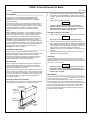
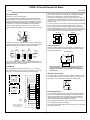
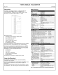
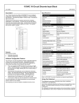
This Datasheet for the
IC660BBD101
Block 115Vac I/O Low Leakage 8 Circuits
http://www.qualitrol.com/shop/p-14434-ic660bbd101.aspx
Provides the wiring diagrams and installation guidelines for this GE Series 90-30
module.
For further information, please contact Qualitrol Technical Support at
1-800-784-9385
[email protected]
115VAC 8-Circuit Discrete I/O Block
June 2002
GFK-0035D
Description _____________________________________
Specifications _________________________________
The 115VAC Low-leakage I/O Block (IC66*BBD101) is an intelligent,
configurable module that interfaces discrete sensors and actuators
to a communications bus. The block has eight identical 115VAC
circuits. Each circuit can be used as either an input or an output.
Catalog Numbers
Block
Electronics Assembly
Terminal Assembly
Block Specifications
Size (height x width x depth)
Weight
LEDs (I/O Block)
LEDs (each circuit)
Block to Block Isolation
Heat Dissipation
115V 50/60 Hz
In/Out
Block features include:
Selectable input Filter Time from 10ms to 100ms.
Output feedback for monitoring.
Output powerup defaults.
Outputs hold last state or default.
Pulse Testing for outputs.
Bus Switching Module control.
Control power for the block is tapped off the input/output device
voltages wired to the terminals. No separate block power supply is
needed.
Each circuit has electronic fusing that shuts down the circuit in 5ms
if output current exceeds 30 Amps with the output turned on, or 20
Amps after 2 cycles. The circuit is easily restored by command from
a Hand-held Monitor or the CPU.
Block diagnostics include:
8.83” (22.44cm) x 3.34” (8.48cm)
x 3.91” (9.93cm)
4 lbs. (1.8 kg)
Unit OK, I/O Enabled
On logic side of switch
1500V
16W maximum with 8 inputs, 43.5W
maximum with 8 outputs on at 2 Amps.
8.5 Watts
Standby power (all inputs and
outputs off)
Operating voltage (single source)
93-132VAC
Frequency
47-63 Hz
Power supply dropout time
1 cycle (16.7ms at 60Hz, 20ms at 50Hz)
Input Specifications
Non-tristate input
OFF state min. voltage across input device (IN to H)
60V RMS
OFF state, max. leakage through input device
1.5mA
ON state, max. voltage across input device (IN to H)
20V RMS
ON state, max. switch current threshold
6mA RMS
Tristate input
OFF state, acceptable voltage across input device (IN to H) 16V RMS-40V
RMS,
ON state, max. voltage across input device (IN to H)
4V RMS
Input load network
Resistor to N:
13K Ohms
Capacitor to H:
0.10 µf
Input processing time (typical)
2ms + filter
Selectable input filter times
10 to 100ms in 10ms increments
Input diagnostics
Open Wire, Overtemperature, Failed Switch
Output Specifications
Circuit output current (steady state) 2 Amps RMS
Max. inrush current up to 2 cycles 25 Amps peak
Maximum inrush current 2-6 cycles 14 Amps peak
Maximum block output current
15 Amps at 35°C, 7.5 Amps at 60°C
Output Leakage @ 115 VAC
Current at 0 volt output (OUT to N): < 7mA
Voltage at open output (OUT to N): 65 volts
Output switch
Zero crossing
(OFF to ON/ON to OFF)
Maximum switching frequency once per second (high inrush currents)
Turn-on delay
0.5 Hz + 1ms, maximum
Voltage drop
2.5V at 2 Amps, 10V at 30 Amps inrush
Recommended min. load (No Load 25mA resistive, 40mA inductive
disabled)
No Load enabled threshold
50mA
Fusing
Internal electronic short circuit trip. 100ms
long time trip
Output diagnostics
Short Circuit, Overload, No Load, Failed
Switch, Overtemperature
Environmental Specifications
Operating temperature
0° C to +60° C (+32° to +140° F)
Storage temperature
-40° to +100° C (-40° to +212° F)
Humidity
5% to 95% (non-condensing)
Vibration
5-10 Hz 0.2” (5.08mm) displacement,
10-200 Hz at 1G
Features
IC66*BBD101
IC66*EBD101
IC66*TSD100
Overtemperature
Failed Switch
Open Wire for tristate inputs
Overload Detection and Shutdown
No-load Detection
Fault reporting can be enabled or disabled circuit by circuit.
Using this Datasheet ____________________________
This datasheet summarizes information about block installation,
configuration, and diagnostics.
Your primary reference should be the Discrete and Analog Blocks
User’s Manual. It includes detailed instructions for block installation
and configuration.
For additional information about systems and communications,
including bus specifications, refer to the I/O System and
Communications Manual.
Refer to GFK-0867 for product standards and general specifications.
1
115VAC 8-Circuit Discrete I/O Block
June 2002
GFK-0035D
Compatibility __________________________________
This block is fully compatible with Hand-held Monitor model
IC66*HHM501. It may be used with IC66*HHM500; however,
HHM501 is required to change the baud rate or to configure the
block for redundancy.
1.
Unscrew the retaining screws at the top and bottom of the block.
2.
Using a Block Puller (IC660BLM507), engage the tabs in the first
vent slots. Move the tool to the center of the block and squeeze the
handle.
3.
Pull the Electronics Assembly upward.
Warning
If the block will be used on a bus controlled by an IC550 series PLC,
or a host computer equipped with a bus interface module, and the
block will be configured as an inputs-only block, it may be necessary
to upgrade the IC550 bus controller or computer bus interface
module as detailed in the Discrete and Analog Blocks User’s
Manual.
If power is applied to the field terminals, power is also
exposed on the connector pins at the base of the Terminal
Assembly, and electrical shock hazard exists. Do not touch
the connector pins! Death or injury may result.
Block IC66*BBD101 is designed to control small loads without the
addition of parallel load resistance. It is also suitable for installations
where a Class 1 Division 2 rating is required for Factory Mutual.
Inserting an Electronics Assembly
1.
This block is backward compatible with blocks IC66*CBD100 and
BBD100, and may be used to replace them. Electronics Assembly
IC66*EBD101 replaces IC66*ELD100 and EBD100. Terminal
Assemblies IC66*TSD100E and later are not compatible with earlier
versions of the Electronics Assembly. If the Terminal Assembly will
be used to replace Terminal Assembly IC66*TSD100D or earlier, the
Electronics Assembly must be either replaced with version
IC66*EBD101F or later, or upgraded.
Align the Electronics Assembly in the guides and push down firmly.
Caution
Do not exert excessive force; it may damage the block.
2.
If unusual resistance is met, remove the Electronics Assembly. If
power is applied to the block, DO NOT TOUCH THE CONNECTOR
PINS! Inspect the Terminal Assembly, connector receptacle, and
connector edge board (on the Electronics Assembly). Be sure the
keying matches. Remove any obstacles and reinsert the
Electronics Assembly. Pay close attention to the alignment of the
guide pins.
3.
Secure the Electronics Assembly with the screws on the top and
bottom of the Terminal Assembly.
Installation Instructions ___________________________
Carefully inspect all shipping containers for damage. If any
equipment is damaged, notify the delivery service immediately. Save
the damaged shipping container for inspection by the delivery
service. After unpacking the equipment, record all serial numbers.
Save the shipping containers and packing material in case it is
necessary to transport or ship any part of the system.
Grounding
The block’s mounting screws must not be used as the only means of
grounding the block. Connect the green ground screw on the block to a
reliable ground system using a short wire lead, minimum size AWG #12
(avg 3.3mm2 in cross-section).
Block Mounting
Genius I/O blocks are considered "open equipment" and therefore
must be installed within a protective enclosure. They should be
located in an area that is clean and free of airborne contaminants.
There should be adequate cooling airflow.
Warning
If mounting screws do not make good ground connection and
the ground screw is not connected to a reliable ground, the
block is not grounded. Electrical shock hazard exists. Death or
personal injury may result.
The block can be mounted right side up, or upside down. Leave at
least 2 inches of space between blocks. Mount the block by drilling
two screw or bolt holes for 8-32 hardware. Position the block so that
the notches in the upper and lower flanges line up with the mounting
holes. Mount the block using 8-32 screws. Use star washers to
provide ground integrity.
Block Wiring __________________________________
All terminals accept one AWG #12 wire (avg 3.3mm2 cross-section) or
two AWG #14 wires (each avg 2.1mm2 in cross-section). The minimum
recommended wire size is AWG #22 (avg .36mm2 in cross-section).
Removing an Electronics Assembly
Block terminals can also accommodate spade or ring terminals up to
0.27 inch (6.85mm) wide with a minimum opening for a #6 screw, and up
to 0.20 inch (5.1mm) depth from the screw center to the back barrier.
Be sure unshielded wire ends are not longer than 2 inches (5 cm).
The block’s Electronics Assembly can be replaced with a compatible
model without removing field wiring or reconfiguring the block.
Electronics
Assembly
Do not overtorque the terminal screws. Recommended torque for all
terminals is 6 in/lb (.678 N/M).
Retaining
Screws
(Qty. 2)
Terminal
Assembly
Connector
Pins
2
115VAC 8-Circuit Discrete I/O Block
June 2002
GFK-0035D
Connect a 115 volt AC source to one of the H terminals on the terminal
strip. Connect neutral to an N terminal. All H terminals are internally
bussed, as are all N terminals. Extra power terminals are for
convenience. Depending on the physical layout and current loads, hot
connections can be bussed together and made by one wire to the block
or power source. Neutral connections can also be bussed together and
made by one wire.
Serial Bus Wiring
Terminals 1 to 4 are for the serial bus.
If the block will be used as a BSM Controller, first install the Bus
Switching Module at the block’s serial bus terminals. Then connect
the serial bus cables to the BSM terminals, as described in the Bus
Switching Module datasheet. Wire either of the BSM’s pigtail wires
to terminal 10. Connect the second BSM wire to an N terminal.
Any circuit can be an input or output. Connect the power source through
the input device (such as a switch) to a discrete input circuit on the
block. For outputs, power is routed through the block electronics to a
discrete circuit and applied to a load. Connect the load return to the N
terminal. Make all power connections on the block to the same 120 VAC
phase. Different blocks can have different phases between them.
Using one of the cable types recommended in the System and
Communications User’s Manual, connect the serial bus to terminals
1- 4.
BLOCK 1
BLOCK 2
115 VAC
PHASE 1
1
SERIAL 1
2
SERIAL 2
3
SHIELD IN
4
SHIELD OUT
INPUT
DEVICE
OUTPUT
DEVICE
If the block is at either end of the bus, connect a terminating resistor
of the appropriate type (see the System and Communications User’s
Manual for details) across its Serial 1 and Serial 2 terminals.
Start
of Bus
OUTPUT
DEVICE
N
H
N
N
Power Disconnects
Since block power is the same as circuit power, it is important to wire
block power disconnects so that block power and input power will be
removed at the same time.
Terminating
Resistor
POWER DISCONNECT
AC
BLOCK
YES
NO
Serial 1
Serial 2
Shield In
Shield Out
Serial 1
Serial 2
Shield In
Shield Out
INPUT
DEVICE
N
End
of Bus
Terminating
Resistor
115 VAC
PHASE 2
H
H
~
If you want to disable the block without removing power from input
devices, use a Block Puller to unplug the Electronics Assembly. Do
not disconnect H or N to remove power.
LOAD
N
Caution
If I/O circuit power is not removed at the same time as block
power, the block may power up when multiple inputs are
activated, even though one leg of power has been removed
from the block.
Field Wiring
Connect wiring for I/O devices to terminals 10 - 17. Connect twowire output devices to N, and two-wire input devices to H, as shown
below left. Connect three-wire devices as shown below right.
Wiring for Tristate Inputs
Output Signal
(hot not used)
Neutral
N
Typical Output
Device Wiring
(10-17)
N DEVICE 1
H
N DEVICE 2
H
N DEVICE 3
H
N DEVICE 4
H
N DEVICE 5
H
N DEVICE 6
H
N DEVICE 7
H
N DEVICE 8
H
Input Signal
(10-17)
H
(neutral not used)
Typical Input
Device Wiring
H
AC
Power
Source
~
N
Note: Terminals 5-9 and
18-22 are connected in the
Terminal Assembly
5
H
6
H
7
H
8
H
9
H
10
1
11
2
12
3
13
4
14
5
15
6
16
7
17
8
18
N
19
N
20
N
21
N
22
N
If an input circuit should report open wire conditions, install a 5.1K ohm,
1/2 Watt or larger non-inductive resistor across the dry contacts of the
input device. The circuit must be configured as a Tristate Input.
H
IN
~
N
External Suppression
If a contact is wired between the block and a load, install suppression
across the load. Resistor capacitor suppressors are preferred for low
current, high inductance loads. For a high-power load, instead use a
voltage-clamping device such as a MOV. RC suppressors are also
recommended to reduce electromagnetic interference.
Power supply-side switches may require line to line suppression if power
is to be switched with devices energized.
See the Discrete and Analog Blocks User’s Manual for more information
about using suppression.
3
115VAC 8-Circuit Discrete I/O Block
June 2002
GFK-0035D
Diagnostics ____________________________________
Block Operation ________________________________
Block diagnostics are listed below. Overload and No Load reporting are
optional features that can be disabled during block configuration.
The 115VAC Low-leakage I/O block has eight identical circuits rated
to operate at a nominal 115 volts AC. It can be used as combination
input/output, inputs-only or outputs-only block.
Open Wire: Voltage, but no current on tristate input.
Overtemperature: Block’s internal temperature is above 100° C.
If the block is configured as a combination block, circuits can be any
mix of inputs and/or outputs. The actual state of each output circuit
will be returned to the CPU in the corresponding input reference
location. The CPU can monitor the feedback state to verify (after an
appropriate delay) that the output switching device has operated
properly and that the load has the proper voltage and current
applied.
Short Circuit: Instantaneous current on an output exceeds 30A during
first two line cycles or 20A thereafter. Output is turned off automatically.
Overload: A load exceeds 2.8A (2.0A RMS) continuously for 100ms.
Output is turned off automatically.
No Load: Load does not continuously draw 50mA from the output
circuit.
If the block is configured as an inputs-only block, all circuits must be
regular inputs or tristate inputs.
Failed Switch: May mean output’s internal feedback state does not
match its commanded state. False Failed Switch diagnostics may be
reported if an external device like a manual switch is wired in parallel
with an output. Several other Failed Switch faults may be reported on
inputs and outputs, indicating a need to replace the Electronics
Assembly.
If the block is configured as an outputs-only block, all circuits must
be outputs; no feedback analysis will be performed.
Each circuit has its own LED. If the circuit is used as an input, the
LED indicates the presence of threshold voltage at the input
terminal. If the circuit is used as an output, the LED indicates the
state commanded by the CPU.
Configuration _________________________________
First, the block must be configured with a Hand-held Monitor to:
115 VAC “H”
H
Configured
as an
Input
*
Input
Device
Configured
as an
Output
Smart
Switch
Processor
Preload
Resistor
13K
Output
Device
Terminal
Assembly
Internal
Circuits
Feature
LEDS _____________________________________
The block's Unit OK and I/O Enabled LEDs show its operating
status:
ON
ON
I/O
Enabled
ON
OFF
ON
Blinking
Blinking
Blinking
ON
OFF
Alternate Blinking
Synchronous
Blinking
OFF
Don’t
Care
In addition, unless all circuits on the block will be inputs, the Block
I/O Type must be set to either Outputs or Combination on the
Program Block ID screen.
Note: If a block is configured offline, it must be properly grounded and
have a 75 Ohm resistor installed across its Serial 1 and Serial 2
terminals. See the Discrete and Analog Blocks User’s Manual for
instructions.
115 VAC “N”
* .2µF for Block IC66*BBD100
.1µF for Block IC66*BBD101
Unit OK
Enter its Reference Number (required only for IC600 and IC550
series PLCs only).
The rest of the features can be configured either using a Hand-held
Monitor, or by sending a Write Configuration datagram to the block from
the host.
N
Field
Connections
Enter its Device Number (serial bus address).
Internal +5V
MOV
1-8
Meaning
Block functioning, CPU communicating
Block functioning
No CPU communications for 3 bus scans
Block functioning, Circuit forced
Circuit fault, CPU communicating
Circuit fault
No CPU communications for 3 bus scans
Circuit fault, Circuit forced
No CPU communications - block number
conflict
No block power, or block faulty
For each input circuit, the circuit LED indicates the presence of
threshold voltage at the input terminal. Output circuit LEDs show the
state commanded by the CPU.
4
Device Number
Circuit
/ Block
Block
Factory
Setting
null
Reference Address
Block I/O Type
Baud Rate
Block
Block
Block
Pulse Test
Input Filter Time
Overload Shutdown
Circuit I/O Type
Report Faults
Hold Last State
Output Default State
BSM Present
BSM Controller
Output Default Time
CPU Redundancy
Duplex Default
Configuration
Protection
Block
Block
Circuit
Circuit
Circuit
Circuit
Circuit
Block
Block
Block
Block
Block
Block
none
input
153.6
std
enabled
20ms
yes
input
yes
no
off
no
no
2.5 sec
none
off
disabled
Selections
0 to 31 (a number must be
selected)
Depends on host CPU type
input, output, combination
153.6 std, 153.6 ext, 76.8, 38.4
Kbd
enabled, disabled
10 to 100ms
yes, no
input, output, tristate input
yes, no
yes, no
on, off
yes, no
yes, no
2.5 or 10 seconds
none, hot standby, duplex
on, off
enabled, disabled