1
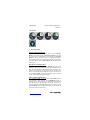
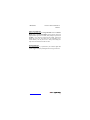
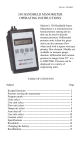
M2 Series
Instruction Manual 9R000045-A
APR2007
M2 – SERIES USER MANUAL
SMART MANOMETER
ROOTS METER TESTER
Meriam Process Technologies’ M2 Series Products (Smart
Manometer and Roots Meter Tester products) are
microcontroller based pressure sensing devices used to
directly measure pressure. Differential, Gauge, Absolute and
Wet/Wet pressure sensors are supported (see Specification
section for supported type and pressure ranges). Pressure can
be displayed in selectable engineering units of measure.
ATEX rating:
0539
II 1 G
Ex ia IIC T4
(Tamb. -5ºC to +50ºC)
DEMKO 06 ATEX 0615699
IP40
www.meriam.com
page 1 of 31
M2 Series
Instruction Manual 9R000045-A
APR2007
Table of Contents
User Interface ................................................................................ 3
1. Keypad Functions ............................................................... 3
ON/OFF & BACKSPACE KEY .................................... 3
MIN/MAX & UP ARROW KEY................................... 3
HOLD & DOWN ARROW KEY................................... 3
PRGM & ENTER KEY ................................................. 4
BACKLIGHT KEY........................................................ 4
2. Zeroing the Manometer....................................................... 5
3. Program Mode .................................................................... 5
Units Select.................................................................... 6
User Unit Select......................................................... 7
Flow Unit Select........................................................ 8
Damp Rate Select........................................................... 9
User Info Select ........................................................... 10
Auto Shut-Off.......................................................... 11
Lockout Select......................................................... 12
Header Name........................................................... 13
Contrast Select ............................................................. 14
Data Logging ............................................................... 15
Leak Test ..................................................................... 16
Re-Calibration ............................................................................. 17
RE-CALIBRATION – 1 Point EDIT and START ................. 19
RE-CALIBRATION – 5 Point EDIT ..................................... 20
RE-CALIBRATION – 5 Point START.................................. 21
RE-CALIBRATION – Restore Factory Defaults ................... 22
Specifications .............................................................................. 23
Certification/Safety/Warnings ..................................................... 25
Changing the Batteries................................................................. 26
User Connections ........................................................................ 28
Contact Information..................................................................... 30
Roots Meter Tester Instructions................................................... 31
www.meriam.com
page 2 of 31
M2 Series
Instruction Manual 9R000045-A
APR2007
User Interface
1.
Keypad Functions
ON/OFF & BACKSPACE KEY
Turns the manometer on and enters the unit into the Measure
Mode. Pressing the key while in the Measure Mode turns the unit
off. It also serves as a backspace key when editing in the Program
Mode. The key takes the user out of a programmable register
without changing the previous setting. Pressing this key repeatedly
will return the user to the Measure Mode and then shut off the
manometer.
MIN/MAX & UP ARROW KEY
In the Measure Mode activates the Min/Max function of the
manometer. When activated the minimum value is displayed on the
upper left of the display and the maximum value on the upper right.
This key also deactivates and resets this function. The key is
used to scroll through the programmable registers when the unit is
in the Program Mode. Once a programmable register is selected
the key can be used to edit that register.
HOLD & DOWN ARROW KEY
In the Measure Mode toggles on/off the display Hold function.
This freezes the value displayed. If the MIN/MAX function is
activated, those values are also frozen. With HOLD activated, the
letter “H” appears in the lower left of the display. The key is
used to scroll through programmable registers with the unit in the
Program Mode. Once a programmable register is selected the key can be used to edit that register.
www.meriam.com
page 3 of 31
M2 Series
Instruction Manual 9R000045-A
APR2007
PRGM & ENTER KEY
Puts the manometer into the Program Mode from the Measure
Mode. When in the Program Mode, pressing this key selects the
programmable register to be edited (with prompt for password if
Lockout is set). After the register has been edited, pressing the
PRGM key enters the new setting into the manometer’s nonvolatile memory. This key also acts as a key when editing user
input such as the header name and user units.
BACKLIGHT KEY
The BACKLIGHT key, represented by the standard light bulb
symbol, toggles the display backlight between red, green and off.
www.meriam.com
page 4 of 31
M2 Series
2.
Instruction Manual 9R000045-A
APR2007
Zeroing the Manometer
To zero the manometer, first turn off pressure sources and vent
pressure ports to atmosphere. The display should read close to zero.
Press the MIN/MAX and HOLD keys at the same time and then
release. This begins the zeroing process. The top line of the display
reads “ZERO IN PROGRESS” while the bottom line counts down
from 9. The process is complete when the unit returns to Measure
Mode. The lockout function, if enabled, does not interfere with the
zeroing of the manometer.
Note: The smart manometer can only be zeroed if the new zero
value is within +/-5% (of FS) of the original factory calibrated zero.
If the zero procedure generates a new zero value outside this limit
a “ZERO RANGE ERROR” message appears indicating that the
procedure failed.
3.
Program Mode
The program mode is used to configure the manometer for
Measure Mode operation. After the PRGM key is pressed in
Measure Mode, the top line of the display reads “PROGRAM
MODE”. The bottom line reads “UNITS SELECT”. Press the or
arrow keys to scroll through the Program Mode to the desired
register. The configurable registers that are found in Program
Mode are Units Select, Damp Rate Select, User Info Select,
Contrast Select, Data Logging, Leak Test and Exit. Two submodes under “Units Select” are provided: User Unit Select and
Flow Unit Select. Press the PRGM key to select either of these
sub-modes and set up their respective function. The manometer
can be put into Program Mode at any time during Measure Mode
operation by pressing the PRGM key. If Lockout is set, the correct
code must be entered when prompted.
www.meriam.com
page 5 of 31
M2 Series
Instruction Manual 9R000045-A
APR2007
Units Select
The standard engineering units available on the Smart Manometer
are:
PSI
inH20 (@20°C, 60°F and 4°C)
Kg/cm2
kPa
mbars
Bars
cmH2O (@ 20°C)
inHg (@ 0°C)
mmHg (@ 0°C)
User Units
Flow Units
To change the engineering units the manometer should be “ON”
and in Measure Mode. Then follow these steps:
Keystroke
1. Press the PRGM key.
2. Press the PRGM key.
3. Press the up or down
arrow key until desired
engineering unit is
displayed.
4. Press the PRGM key to
select the engineering unit.
5. Press the down arrow
key.
6. Press the PRGM key.
www.meriam.com
page 6 of 31
Display
Top line reads “PROGRAM
MODE” and bottom line reads
“UNITS SELECT”.
Top line reads “UNITS
SELECT” and bottom line shows
current engineering units.
Engineering units on bottom line
of display change.
Top line reads “PROGRAM
MODE” and bottom line reads
“UNITS SELECT”.
Bottom line reads “EXIT”.
Display returns to Measure Mode
in new engineering units.
M2 Series
Instruction Manual 9R000045-A
APR2007
User Unit Select
Engineering units not included in the standard selection can be
programmed into the manometer using the Units Select register in
the program mode. The value programmed into this register is
used to calculate the desired unit of measure. An example of
converting to “Feet of H2O” will be shown in the following steps,
using the conversation factor of 1 PSI = 2.30894 FT H2O.
Keystroke
1. Press the PRGM key.
2. Press the PRGM key.
3. Press the up or down
arrow key until “USER
UNIT SELECT” is
displayed.
4. Press the PRGM key.
See note 1 at bottom of
this table.
5. Press the PRGM key to
change the value.
6. Start entering the
conversion factor by
pressing the up arrow key
until the first digit reads 2.
7. Press the right arrow
key to enter the value “2”
and advance the cursor to
the next digit.
8. Repeat step 6 and 7
until bottom line reads
2.30894
9. If an error is made use
the left arrow key to move
the cursor back to the
incorrect digit. Then press
up or down arrow keys to
www.meriam.com
page 7 of 31
Display
Top line reads “PROGRAM
MODE” and bottom line reads
“UNITS SELECT”.
Top line reads “UNITS
SELECT” and bottom line shows
current engineering units.
Top line reads “UNITS
SELECT”
Bottom line reads “USER UNIT
SELECT”.
Top line reads “VALUE=”.
Bottom line reads “CHANGE?:
YES”.
Top line reads “USER UNIT
VALUE”.
Top line reads “USER UNIT
VALUE”.
Bottom line reads “20000000”.
Cursor flashes to the right of the
“2”. Now numbers, decimal
point or blank space can be
entered.
Bottom line reads “2.30894”.
Last digit “4” is blinking.
The digit that is corrected is
blinking.
M2 Series
display the correct value.
10. Press the PRGM key
until the display changes.
See note 1 at bottom of
this table.
11. Press the PRGM key.
12. Follow steps 6-8
above to enter “FT H2O”.
13. Press the PRGM key.
14. Press the down arrow
key.
15. Press the PRGM key.
Instruction Manual 9R000045-A
APR2007
Top line reads “VALUE=”.
Bottom line reads “CHANGE?:
YES”.
Top line reads “USER UNIT
NAME”.
Bottom line reads “FT H2O”.
Last letter “O” is blinking.
Top line reads “PROGRAM
MODE”.
Bottom line reads “UNITS
SELECT”.
Bottom line reads “EXIT”.
Manometer returns to Measure
Mode. Units Display shows “FT
H2O”.
Note 1: If at steps 4 or 10 the “VALUE=” is the desired value,
press the up or down arrow key. This will toggle the bottom line
from the default “CHANGE?: YES” to “CHANGE?: NO”. Step 5
would then jump to step 10. Step 11 would then jump to step 13.
Flow Unit Select
Smart Manometers that use differential pressure sensors can be
programmed to read out flow measurement units such as CFM or
L/min. The primary element must be a differential pressure
producing, square root type of device, such as a pitot tube, orifice
plate or venturi.
The flow constant and flow units description are programmed into
the manometer using the same keystrokes used in the User Unit
Select programming. At step 3 choose “FLOW UNIT SELECT”
instead of “USER UNIT SELECT”.
www.meriam.com
page 8 of 31
M2 Series
Instruction Manual 9R000045-A
APR2007
Damp Rate Select
Adjustable exponential type damping is available to steady the
display when measuring pulsating pressure or flow. The Smart
Manometer has a range of damping rates; 0.1, 0.2, 0.5, 1, 2, 5, 10,
or 25 seconds. Exponential damping shows approximately 70% of
a step change in pressure upon the next display update. When set
for 5 second time constant, it takes 5 seconds from the time of the
step change until the manometer displays the full value of the new
pressure.
To set the damp rate:
Keystroke
1. Follow the steps on
page 4 to put the unit in
Program Mode
2. Press the up arrow
key.
3. Press the PRGM key.
4. Press the up or down
arrow key until the
desire desired damp rate
is displayed on the
bottom line.
5. Press the PRGM key.
Display
Top line reads
PROGRAM MODE” and
bottom line reads “UNITS
SELECT”.
Bottom line reads “DAMP
RATE SELECT”.
Top line reads “DAMP
RATE SELECT”.
Bottom line shows damp
rate in seconds.
6. Press the down arrow
key.
Top line reads
“PROGRAM MODE” and
bottom line reads “UNITS
SELECT”.
Bottom line reads
“EXIT”.
7. Press the PRGM key.
Returns to Measure Mode.
www.meriam.com
page 9 of 31
M2 Series
Instruction Manual 9R000045-A
APR2007
User Info Select
The User Info Select registers are designed to provide the user with
information on the hardware and software in the manometer. This
register provides read only information on the sensor’s serial
number, software version and date of manufacture. It also allows
the user to edit the Auto Shut-Off, Lockout and Start-Up Header
Name features.
To configure the User Info Select registers follow the steps shown
on the following page.
Keystroke
1. From the Measure Mode
press the PRGM key.
2. Press the up arrow key
twice
3. Press the PRGM key.
4. Press the up arrow key.
5. Press the up arrow key.
6. Press the up arrow key.
Instructions to set AUTO
SHUT-OFF are in this
manual.
7. Press the up arrow key.
Instructions for using
LOCKOUT are on page 12.
8. Press the up arrow key.
Instructions for editing the
Header are on page 13.
9. Press the left arrow key
to go back to “USER INFO
SELECT” screen.
www.meriam.com
page 10 of 31
Display
Top line reads “PROGRAM
MODE” and bottom line reads
“UNITS SELECT”.
Bottom line changes to “USER
INFO SELECT”.
Bottom line shows serial
number.
Software version number
shown.
Manufacture date shown.
Top line reads “AUTO SHUT
OFF” and bottom line reads
“ENTER TO SELECT”.
Top line reads “LOCKOUT
CODE” and bottom line reads
“ENTER TO SELECT”.
Top line reads “HEADER
NAME” and bottom line reads
“MERIAM”. The cursor flashes
at bottom left.
Top line reads “PROGRAM
MODE” and bottom line reads
“USER INFO SELECT”.
M2 Series
Instruction Manual 9R000045-A
APR2007
Auto Shut-Off
Enabling the Auto Shut-Off feature allows the manometer to turn
itself off after a user selected period of keypad inactivity.
Selectable options include DISABLED, 10 Minutes (which is the
factory shipped default), 20 Minutes, 30 Minutes, 45 Minutes and
60 Minutes. Disabling this feature limits the manometer to being
turned off by using the ON/OFF key only.
To configure auto shut-off follow these steps:
Keystroke
1. Follow steps 1-6 in the
User Info Select table.
2. Press the PRGM key,
then the up or down
arrow keys until the
desired shut-off time is
shown.
3. Press the PRGM key.
4. Press the left arrow key
twice.
www.meriam.com
page 11 of 31
Display
Top line reads “AUTO SHUTOFF” and bottom line reads
“ENTER TO SELECT”.
Top line reads “AUTO SHUTOFF” and bottom line toggles to
“DISABLED”, “10”, “20”, “30”,
“45” and “60” minutes .
Desired Auto Shut-Off time is
selected, top line reads “AUTO
SHUT-OFF” and bottom line
reads “ENTER TO SELECT”.
Returns to Measure Mode.
M2 Series
Instruction Manual 9R000045-A
APR2007
Lockout Select
Enabling the Lockout feature prevents unauthorized users from
making changes to the configuration of the manometer. To enter
the Program Mode, the user must first enter the “password” (twodigit Lockout Code) within approximately 40 seconds when
prompted. Failure to enter the correct two digit code within
approximately 40 seconds will return the unit to Measure Mode.
Any two-digit numeric code can be programmed. The factory
Lockout Code of 00 (which is the default as shipped from the
factory) disables the Lockout.
To set the Lockout Code follow these steps:
Keystroke
1. From the Measure
Mode press the PRGM
key. If the Lockout is set,
enter the correct
“password” when
prompted.
2. Press the up arrow key
twice.
3. Press the right arrow
key then the up arrow key
four times.
4. Press the right arrow
key, then press the up or
down arrow keys to
change the first digit.
Press the right arrow key
to proceed.
5. Press the right arrow
key when the desired code
is set. Lockout is
activated.
6. Press the left arrow key
twice.
www.meriam.com
page 12 of 31
Display
Top line reads “PROGRAM
MODE” and bottom line reads
“UNITS SELECT”.
Bottom line reads “USER INFO
SELECT”.
Top line reads “LOCKOUT
CODE” and bottom line reads
“ENTER TO SELECT”.
Bottom line shows the old
Lockout Code. The cursor flashes
at the first position while the
value is changed, the cursor
moves to the right position once
the right arrow key is pressed.
Top line reads “LOCKOUT
CODE” and bottom line reads
“ENTER TO SELECT”.
Returns to Measure Mode.
M2 Series
Instruction Manual 9R000045-A
APR2007
Header Name
Follow the steps below to edit the Header Name.
Keystroke
1. From the Measure Mode
press the PRGM key.
2. Press the up arrow key
twice.
3. Press the PRGM key.
4. Press the up arrow key
five times.
5. If header is correct press
backspace key. If editing is
desired proceed to step 7.
6. Press the left arrow key.
7. Press the up or down
arrow keys to set the
correct alpha-numeric
value.
8. Press the right arrow key
to accept entry.
9. Repeat steps 8 and 9
until the desired Header is
shown.
10. If an error is made press
the back arrow key until the
cursor is over the incorrect
value. Follow step 8 to
correct. Press the right
arrow key to advance the
cursor without changing
values.
11. When the Header is
complete press the PRGM
key until header accepted.
12. Press the left arrow key.
www.meriam.com
page 13 of 31
Display
Top line reads “PROGRAM
MODE” and bottom line reads
“UNITS SELECT”.
Bottom line changes to “USER
INFO SELECT”.
Bottom line shows serial
number.
Top line reads “HEADER
NAME” and bottom line reads
“MERIAM”. The cursor flashes
at bottom left.
Top line reads “PROGRAM
MODE” and bottom line reads
“USER INFO SELECT”.
Returns to Measure Mode.
Displays a number between 0
and 9, a letter from A to Z, / or a
blank space.
Cursor advances one space to
right.
Top line reads “PROGRAM
MODE” and bottom line reads
“UNITS SELECT”.
Returns to Measure Mode.
M2 Series
Instruction Manual 9R000045-A
APR2007
Contrast Select
The Contrast Select register allows the user to adjust the character
contrast of the LCD display to provide the best visibility for the
ambient light conditions.
To adjust the contrast, follow these steps:
Keystroke
1. From the Measure Mode
press the PRGM key.
2. Press the up arrow key
three times.
3. Press the PRGM key.
4. Press the up or down
arrow keys to increase or
decrease the contrast value.
A low number gives
maximum contrast and a
high number gives
minimum contrast.
5. Press the PRGM key.
6. Press the left arrow key.
Display
Top line reads “PROGRAM
MODE” and bottom line reads
“UNITS SELECT”.
Bottom line reads
“CONTRAST SELECT”.
Top line reads “CONTRAST
SELECT” and bottom line
shows a numerical value.
LCD lightens or darkens
depending on the value set.
Top line reads “PROGRAM
MODE” and bottom line reads
“UNITS SELECT”.
Returns to Measure Mode.
If an error is made during the contrast adjustment, pressing the key
returns the display to the previous contrast setting.
www.meriam.com
page 14 of 31
M2 Series
Instruction Manual 9R000045-A
APR2007
Data Logging
Data Logging can be used to record pressure measurements. Two
record modes are supported: automatic and manual. In automatic
mode, a pressure value is captured every 5 seconds for 20 minutes,
resulting in 240 stored values. In manual mode, a pressure value is
captured each time the PRGM key is pressed up to 240 values. The
data collected during a logging session can be viewed upon
completion.
Keystroke
1. From the Measure Mode
press the PRGM key.
2. Press the up arrow key
four times.
3. Press the PRGM key.
4. Press the PRGM key.
5. Press the PRGM key at
AUTO to start automatic
logging or at MANUAL to
start manual logging mode.
6. To stop recording values
at any time, press the key.
7. To access recorded
values, press the key.
8. To view recorded values,
press the PRGM key.
9. Press the key 3 times.
www.meriam.com
page 15 of 31
Display
Top line reads “PROGRAM
MODE” and bottom line reads
“UNITS SELECT”.
Bottom line reads “DATA
LOGGING”.
Top line reads “DATA
LOGGING” and bottom line
reads “RECORD”.
Top line reads “RECORD
MODE” and bottom line reads
“AUTO” or “MANUAL”.
Top line reads
“RECORDING X” and
bottom line reads “XX.XX
UNITS”. AUTO records value
every 5 seconds. Manual
records value each time PRGM
key is pressed.
Top line reads “DATA
LOGGING” and bottom line
reads “RECORD”.
Top line reads “DATA
LOGGING” and bottom line
reads “VIEW”.
Top line reads “DATA LOG:
1” and bottom line displays
the value. Continue pressing
the key to view all values.
Returns to Measure Mode.
M2 Series
Instruction Manual 9R000045-A
APR2007
Leak Test
The Leak Test feature allows the user to determine the leak rate in
the pneumatic system being monitored. Once configured, Leak
Test monitors the measured pressure over time and displays the
leak rate in the pressure units per minute at the conclusion of the
test. The maximum configurable leak test period is 1440 min (1
day). Pressing any key during the leak test will abort the test.
To enable Leak Test follow these steps:
Keystroke
1. From the Measure Mode
press the PRGM key.
2. Press the down arrow key
twice.
3. Press the PRGM key.
4. Press the PRGM key.
5. Use the up, down and
right keys to input test
period
6. Press the PRGM key.
7. Press the up arrow key
once.
8. Press the PRGM key.
Display
Top line reads “PROGRAM
MODE” and bottom line reads
“UNITS SELECT”.
Bottom line reads “LEAK
TEST”.
Top line reads “LEAK TEST”
and bottom line reads
“CONFIGURE”.
Top line reads “Leak Test
Period” & bottom “X.X MIN”.
Bottom line reads desired
period; Ex. “ 20.0 MIN”.
Top line reads “LEAK TEST”
and bottom line reads
“CONFIGURE”.
Top line reads “LEAK TEST”
and bottom line reads “PRGM
TO START”.
Top line displays MIN/MAX
pressure values at left/right.
Bottom line reads the current
pressure value and units.
At end of test period, top line
displays the leak rate in units
per minute. Bottom line shows
the current pressure reading.
www.meriam.com
page 16 of 31
M2 Series
Instruction Manual 9R000045-A
APR2007
Re-Calibration
The Manometer can be re-calibrated in the field for zero, span, and
linearity. The proper primary standards must be available prior to
calibrating the Manometer. These standards should meet the
accuracy requirements for your company or industry. Meriam
Process Technologies follows the guidelines established by ANSI /
NCSL Z540-1-1994 which requires that the primary standard be 4
times more accurate than the unit under test.
The re-calibration is not intended to replace the Factory Lab
Calibration Procedure. It is intended to correct the curve fit if the
actual sensor characteristics change slightly over time.
For sensors up to 200 PSI, Meriam recommends a ±0.0015% of
reading deadweight tester. For sensors 200 PSI and above, a
±0.0030% of reading deadweight tester is recommended. If
calibrating using inches of water units, be sure to match the
reference temperature of water in both the unit under test and the
M2.
1-point (within upper 50% of Full Scale), 5-point (nominal values
of 0%, 25%, 50%, 75% & 100% of Full Scale), and restore factory
default re-calibration options are offered. For the 5-Point recalibration, points 2, 3 and 4 can be adjusted within ±1% of
reading around the nominal values. Point #5 can be adjusted within
-1% of reading around nominal. Point #1 is fixed.
For example: for a 2000 inH2O sensor, Point # 2 (25%) can be
edited form 495 to 505 inH2O. Point #5 (100%) can be edited
from 1980 to 2000 inH2O.
The unit can only be re-calibrated if the calibration points are
within 5 times the accuracy of the original factory calibration (e.g.
@ 0.05% accuracy, the point limit is ±0.25% of Full Scale). If the
re-calibration procedure generates a new value outside this limit
the procedure will fail. In this case the unit would need to be
returned to the factory for service.
www.meriam.com
page 17 of 31
M2 Series
Instruction Manual 9R000045-A
APR2007
Once a re-calibration has been performed (either 1-point or 5point) the unit will continue to allow future re-calibrations only
with that type of re-calibration. In order to enable the other recalibration type, the user must first restore the re-calibration data to
the factory defaults.
www.meriam.com
page 18 of 31
M2 Series
Instruction Manual 9R000045-A
APR2007
RE-CALIBRATION – 1 Point EDIT and START
To perform a 1-point re-calibration, apply a pressure between 50%
and 100% of Full Scale and then follow these steps:
Keystroke
1. With unit OFF, press and
hold the MIN/MAX key,
turn the unit on by pressing
the ON/OFF key, then
release MIN/MAX.
2. Press the up arrow key
until “START” is displayed
on the bottom line.
3. Press the PRGM key.
4. Press the PRGM key.
5. Press the up/down arrow
keys to edit the selected
digit. Use the left/right arrow
keys to change the cursor
position. Value entered must
be 50-100% of FS.
6. Press the right arrow key
while on the right most digit
to proceed.
7. Apply the input pressure
indicated using an
appropriate reference
standard; press PRGM key.
8. Press the left arrow key.
www.meriam.com
page 19 of 31
Display
Top line reads “RE-CAL”.
Bottom line reads “EDIT”.
Top line reads “RE-CAL”.
Bottom line reads “START”.
Top line reads “RE-CAL
START”.
Bottom line reads “1-POINT”.
Top line reads “CAL POINT”
and bottom line displays the
cal point value.
Bottom line displays the cal
point value. The cursor flashes
at the first position while the
value is changed, then moves
to the right position when the
right arrow key is pressed.
Top line reads “APPLY:”
Bottom line displays the “CAL
POINT” value.
Top line reads “RE-CAL”.
Bottom line reads “START”,
Manometer has been
recalibrated.
Returns to Measure Mode
M2 Series
Instruction Manual 9R000045-A
APR2007
RE-CALIBRATION – 5 Point EDIT
To edit the calibration points for a 5 Point re-calibration follow the
steps below.
NOTE: If the factory default values are acceptable, skip this
section and proceed to the re-calibration 5-Point START procedure.
Keystroke
1. With unit OFF, press and
hold the MIN/MAX key,
turn the unit on using the
ON/OFF key, then release
2. Press the PRGM key.
3. Press the up/down arrow
keys to edit the selected
digit. Use the left/right
arrow keys to change the
cursor position. Note: For
0% go directly to step 4.
4. Press the right arrow key
while on the right most digit
to proceed.
5. Repeat steps 3 and 4 for
CAL POINTS 2, 3, 4 and 5.
6. After editing CAL
POINT 5 press the right
arrow key while on the right
most digit to proceed.
7. To perform the 5-point
re-cal, press the up arrow
key until START is
displayed on the bottom
line.
OR
To exit without performing
the 5-point re-cal press the
left arrow key
www.meriam.com
page 20 of 31
Display
Top line reads “RE-CAL”.
Bottom line reads “EDIT”.
Top line reads “CAL POINT
1”. Bottom line displays the
cal point value.
Bottom line displays the cal
point value. The cursor flashes
at the first position while the
value is changed, then moves
to the right position when the
right arrow key is pressed.
Top line reads “CAL POINT
2”. Bottom line displays the
cal point value.
Top line reads “CAL POINT
2/3/4/5”. Bottom line displays
the cal point value.
Top line reads “RE-CAL”.
Bottom line reads “EDIT”.
Top line reads “RE-CAL”.
Bottom line, “START”.
Continue with 5-Point Recalibration procedure at step 3
on next page.
OR
Returns to Measure Mode.
M2 Series
Instruction Manual 9R000045-A
APR2007
RE-CALALIBRATION – 5 Point START
To begin the 5-point re-calibration procedure, turn the unit OFF
and follow the steps below.
Keystroke
1. Press and hold the
MIN/MAX key and turn the
unit on by pressing the
ON/OFF key.
2. Press the up arrow key
until “START” is displayed
on the bottom line.
3. Press the PRGM key.
4. Press the up arrow key
until “5-POINT” is
displayed on the bottom
line.
5. Press the PRGM key.
6. Vent P1 and P2 ports to
atmosphere and
simultaneously press the
MIN/MAX and HOLD
keys, then release.
7. Press the right arrow key
while on the right most
digit to proceed.
8. Apply the indicated
calibration point pressure
using external pressure
standards. After pressure is
stable, press the right arrow
key.
9. Repeat step 8 for CAL
POINTS 4 and 5.
www.meriam.com
page 21 of 31
Display
Top line reads “RE-CAL”.
Bottom line reads “EDIT”.
Top line reads “RE-CAL”.
Bottom line reads “START”.
Top line reads “RE-CAL
Bottom line reads “1-POINT”.
Top line reads “RE-CAL
START”.
Bottom line reads “5-POINT”.
Top line reads “POINT 1 –
ZERO:”
Bottom line displays live
applied pressure.
Unit takes new zero. Top line
reads “ POINT 1 - ZERO:”
Bottom line displays live
applied pressure. POINT 1 has
been taken.
Top line reads “ POINT 2 APPLY:”.
Bottom line displays the cal
point value to apply.
Top line reads “ POINT 3 APPLY:”.
Bottom line displays the cal
point value to apply.
Top line reads “POINT 4/5 APPLY”
Bottom line displays the cal
point value.
M2 Series
Instruction Manual 9R000045-A
APR2007
10. Use up or down arrow
keys to select NO or YES
when asked “Save?” the
Re-Calibration data.
11. Press the PRGM key at
YES to save the ReCalibration data or at NO to
exit without saving.
10. Press the left arrow key.
Top line reads “SAVE?”.
Bottom line reads “NO” or
“YES”.
Top line reads “RE-CAL”.
Bottom line reads “START”.
Re-cal is complete.
Returns to Measure Mode.
RE-CALIBRATION – Restore Factory Defaults
To restore the re-calibration data to the factory defaults, follow
these steps:
Keystroke
1. With unit OFF, press and
hold the MIN/MAX key,
turn the unit on using the
ON/OFF key, then release.
2. Press the up arrow key
twice.
3. Press the PRGM key.
4. Use the up and down
arrow keys to select YES or
NO when asked to restore
defaults.
5. Press the PRGM key at
YES to restore the Factory
Default Calibration data or
at NO to exit without
restoring.
6. Press the left arrow key.
www.meriam.com
page 22 of 31
Display
Top line reads “RE-CAL”.
Bottom line reads “EDIT”.
Top line reads “RE-CAL”.
Bottom line reads “RESTORE
DEFAULTS”.
Top line reads “RESTORE
DEFAULTS”.
Bottom reads “YES” or “NO”.
Top line reads “RESTORE
DEFAULTS”.
Bottom reads “YES” or “NO”.
Top line reads “RE-CAL”.
Bottom line reads “RESTORE
DEFAULTS”. Factory
defaults have been restored.
Returns to Measure Mode.
M2 Series
Instruction Manual 9R000045-A
APR2007
Specifications
Type and Range and Display Resolution:
Differential Non-Isolated Types:
28 inH2O (1 psid) – XX.YYY
200 inH2O (7.21 psid) – XXX.YY
2000 inH2O (72.1 psid) – XXXX.Y
Gauge Isolated Types:
15 psig – XX.YYY
200 psig – XXX.YY
2000 psig – XXXX.Y
Absolute Isolated Types:
900 mmHg (17 psia) – XXX.YY
2000 mmHg (38 psia) – XXXX.Y
Wet/Wet Types:
1 and 5 psid – X.YYYY
15, 30 and 50 psid – XX.YYY
100, 300 and 500 psid – XXX.YY
Accuracy:
±0.025% of Full Scale or ±0.05% of Full Scale
Includes the combined effects of temperature, linearity,
repeatability, hysteresis and resolution.
Warm up time = 5 minutes.
Unit should be zeroed at working ambient temperature
before use.
Temperature:
Storage = -40°C to +60°C (-40°F to +140°F)
Operating = -5°C to +50°C (23°F to +122°F)
Media Compatibility:
PORTS:
DN: Differential pressure non-isolated sensors for use with
clean, dry, non-corrosive gases only.
DI, GI , AI: Differential, Gauge, or Absolute pressure sensors
for use with gases and liquids compatible with 316L SS
and O-ring material (DI wet/wet differential sensors only)
O-RING Material (for DI sensors only):
Viton (standard)
Buna-N, Neoprene or Ethylene-Propylene(available options)
Pressure Limits:
2 × range on DN units when pressurized on high side only.
150 PSI (10.5 Kg/cm²) static when applied to both sides of
sensor simultaneously
www.meriam.com
page 23 of 31
M2 Series
Instruction Manual 9R000045-A
APR2007
Connection:
1/8” female NPT, 316L SS. P1 is the high pressure
connection and P2 is the low pressure connection.
Differential port shown below.
User must use a wrench on the pressure manifold when
installing user’s 1/8” NPT fitting. Do not tighten the
fitting without using a wrench on the pressure
manifold. Failure to use a wrench on the manifold will
damage the plastic enclosure and void warranty No
torque should be applied to the manifold with respect
to plastic enclosure.
Battery Type:
4 each AA alkaline batteries.
IMPORTANT!!! ATEX certified models require the use
of approved batteries only to maintain the ATEX
certification. Refer to Dwg. No. 9R000056 “M2
Intrinsically Safe Control Document” for a list of
batteries approved for hazardous atmospheres. A copy of
this drawing accompanies each unit shipped.
Remove and / or replace batteries in non-hazardous
areas only.
Battery Operation:
>100 hours continuous use, 1 year shelf life, auto power off
programmable at Disabled, 10, 20, 30, 60 or 90 minutes
Enclosure:
(6.9” × 3.8” × 2.3”) Polycarbonate, Permanently Static
Dissipative, ESD Protection
Enclosure with Boot:
(7.2” × 4.2” × 2.5”)
www.meriam.com
page 24 of 31
M2 Series
Instruction Manual 9R000045-A
APR2007
Certification/Safety/Warnings
The following defines the certification and area classification of
the Manometer product.
Note the following WARNINGS and requirements:
•
•
•
•
Substitution of components may impair Intrinsic Safety
To prevent ignition of flammable or explosive atmospheres,
disconnect power before servicing.
To prevent ignition of flammable or explosive atmospheres,
DO NOT open or service unit, including battery
compartment, in flammable or explosive atmosphere
DO NOT rub, clean or wipe the surface of the
membrane keypad as it may build a static charge
DO NOT mix old batteries with new or mix
batteries from different manufacturers
DO NOT replace batteries in explosive or
hazardous atmosphere
DO NOT use any battery type other than those
listed on Dwg. No. 9R000056 “M2 Intrinsically
Safe Control Document”.
User must use a wrench on the pressure manifold when
installing user’s 1/8” NPT fitting. Do not tighten the fitting
without using a wrench on the pressure manifold. Failure to
use a wrench on the manifold will damage the plastic
enclosure and void warranty No torque should be applied to
the manifold with respect to plastic enclosure.
www.meriam.com
page 25 of 31
M2 Series
Instruction Manual 9R000045-A
APR2007
Changing the Batteries
Adherence to the Specifications and Certification/Safety/Warnings
sections of this manual shall be enforced when changing batteries.
The manometer is powered by four, 1.5 volt AA size batteries.
When the output of the batteries under load drops, the display will
alternate between “LOW POWER DETECT” and “REPLACE
BATTERY”. Low power may affect performance. The unit should
not be used to measure pressure in this condition. All four batteries
should be replaced.
To replace the battery locate the battery compartment at the bottom
rear of the manometer, as shown here.
Remove the two screws on either side of the battery cover by
turning them counterclockwise until the fully disengaged from the
manometer base. Lift the cover from the back of the unit.
Remove the batteries by pulling the positive side first straight out
of the battery compartment. Note the positive (+) and negative (-)
battery polarity markings at the bottom of the compartment, as
shown here.
www.meriam.com
page 26 of 31
M2 Series
Instruction Manual 9R000045-A
APR2007
Install the four batteries by sliding them into the bottom of the
battery slots, making sure the polarity markings on the batteries
align with the markings in the compartment. The battery
compartment has stand offs molded into the side of the
compartment. When a battery is installed with the polarity
reversed, the stand offs prevent the negative battery terminal from
contacting the positive terminal in the battery compartment. The
unit will not power up when a battery is installed this way. Should
this happen, simply reverse the battery to align the polarity.
With the batteries secured in the battery compartment, replace the
compartment cover. The cover has only one correct alignment.
The “WARNING DO NOT OPEN IN EXPLOSIVE ATMOSPHERE”
statement on the battery cover must be visible and aligned in the
middle of the manometer case. To secure the cover, torque the
screws clockwise to 1.6-1.8 in-lbs. Do not over tighten.
www.meriam.com
page 27 of 31
M2 Series
Instruction Manual 9R000045-A
APR2007
User Connections
Connection: 1/8” female NPT, 316L SS. P1 is the high pressure
connection and P2, the low pressure connection.
The pressure connections are marked in two locations, identified as
P1 and P2. One location is the top of the keypad (shown on page
1). The second marking is stamped into the pressure connection
fitting, next to the pressure connections, as shown here.
DN
GI or AI
DI
DI w/ FP
DN w/ PTR
NOTES:
PTR is a “Push to Read Valve” offered as an option for the product.
FP is a “Flushing Port” design offered as an option for wet / wet DI
models
www.meriam.com
page 28 of 31
M2 Series
Instruction Manual 9R000045-A
APR2007
“G” and “A” models have only one used pressure port. The
unused port vents the enclosure/sensor P2 to atmosphere (a
sintered plug or vent is installed in either P1 or P2 as appropriate).
Absolute
Pressure
Differential
A
+
Gauge
Barometric Pressure
or
Atmospheric Pressure
Vacuum
B
–
Absolute Zero
Warning Connection to the incorrect pressure port on DN or
DI differential pressure modules may cause damage to the
pressure sensor. If this sort of damaged occurs, the unit must be
returned to the factory for sensor replacement.
WARNING User must use a wrench on the pressure manifold
when installing user’s 1/8” NPT fitting. Do not tighten the fitting
without using a wrench on the pressure manifold. Failure to use a
wrench on the manifold will damage the plastic enclosure and void
warranty No torque should be applied to the manifold with
respect to plastic enclosure.
www.meriam.com
page 29 of 31
M2 Series
Instruction Manual 9R000045-A
APR2007
Contact Information
If the Manometer can not be zeroed, recalibrated or is damaged, it
must be returned to the factory for servicing. In this case, contact
the Meriam Process Technologies representative in your area or
call the factory at the numbers listed below for a Return Material
Authorization (RMA) number.
Meriam Process Technologies
10920 Madison Ave.
Cleveland, OH 44102
Ph. (216) 281-1100 FAX (216) 281-0228
E-mail [email protected]
All M2 Smart Manometers recalibrated at the factory are returned
with certificates of NIST traceability.
www.meriam.com
page 30 of 31
M2 Series
Instruction Manual 9R000045-A
APR2007
Appendix 1
Roots Meter Tester Instructions
The M201 Roots Meter Test is purpose-designed for natural gas
distribution companies performing drop tests across positive
displacement (rotary vane) meters in the field. This model uses the
same pressure sensor technology and packaging as other M2 Series
products but uses custom firmware to provide a mathematically
averaged pressure from test start to test stop. The user determines
the test duration. A number of the standard M2 Series
programming options are eliminated. Program mode for the M201
includes Units Select, User Info Select and Contrast Select. See
these sections earlier in this manual for more information.
Keystroke
1. Turn unit on using the
ON/OFF key. Unit powers
on ready to start a drop test.
2. Press the HOLD key. This
starts the test. No values are
displayed while pressure
values are stored.
3. Press the HOLD key
again to stop test. Average
pressure for test period is
displayed.
4a. To start a retest, press the
HOLD key. Repeat Step 3.
4b. To start a retest using the
MIN/MAX feature, press the
MIN/MAX key and then
press the HOLD key.
5. Press the HOLD key
again to stop test.
6. Press the left arrow key.
www.meriam.com
page 31 of 31
Display
Reads “Press Hold to Acquire
Data”.
Reads “Acquiring Data..”.
Reads “XX.XX Units” , the
average pressure during the
test period.
Reads “Acquiring Data..”.
Top line shows MIN at left
and MAX at right. Bottom
shows previous test average.
After HOLD key is pressed,
the display reads “Acquiring
Data..”.
If MIN/MAX is on, Top left
reads MIN pressure during
test, top right reads MAX
pressure during test. Bottom
reads the average pressure
during the test period.
Returns to Measure Mode