1
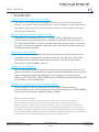
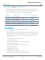
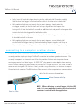
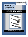
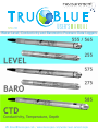
TM
A P R I L 2015
U SER’S M A N U A L
Water Level, Conductivity and Barometric Pressure Data Loggers
[email protected] / www.meas-spec.com/water-level-sensors.aspx
TM
TruBlue ™ User Manual
table of contents
1. Introduction
........................................................................................................ 3
Thank You for Your Purchase .................................................................................................3
About Measurement Specialties............................................................................................3
Website and E-Mail ..............................................................................................................3
Technical Support .................................................................................................................3
Ordering Products and Accessories .......................................................................................3
Manual Content Disclaimer ...................................................................................................3
2 . Tr u B l u e ™ S e r i e s O v e r v i e w .................................................................... 4
3 . U s i n g t h e Tr u W a r e ™ S o f t w a r e P r o g r a m ...................................5
4 . C o n n e c t i o n s a n d F i e l d I n s t a l l a t i o n ...............................................7
Two Types of Field Cable .......................................................................................................7
Interface Cable Assembly.......................................................................................................7
Suspension wire ...................................................................................................................7
Connecting the Data Logger to the Field Cable.......................................................................8
Connecting to a Computer or Other Device.............................................................................9
Vented Interface Cable Assembly......................................................................................... ..9
Suspension Wire.................................................................................................................11
Internal Clock Synchronization.............................................................................................11
General Field Installation.....................................................................................................11
Cable Protection..................................................................................................................12
5. Conductivity
.......................................................................................................12
What is Conductivity?.........................................................................................................12
Types of Conductivity Measurement....................................................................................12
Actual Conductivity.............................................................................................................13
Specific Conductivity...........................................................................................................13
Calibrating the Conductivity Sensor.....................................................................................13
Measurement Specialties, Inc.
1000 Lucas Way, Hampton, VA 23666 USA
www.meas-spec.com
Page 1 of 28
1-757-766-1500
1-800-745-8008
TM
TruBlue ™ User Manual
6 . M a i n t e n a n c e .......................................................................................................15
Cleaning Your Water Level Data Logger...................................................................................................16
7 . Tr o u b l e s h o o t i n g ..............................................................................................................17
8 . W a r r a n t y a n d P r o d u c t R e t u r n P r o c e d u r e s ...............................21
Warranty.....................................................................................................................................................21
Merchandise Return Procedures................................................................................................................21
9 . A p p e n d i x A : Tr u B l u e ™ C o n n e c t i o n D i a g r a m s ......................23
Appendix A: TruBlue™ Connection Diagrams.............................................................................................23
Model 850-00857......................................................................................................................................23
Model 850-00854 .....................................................................................................................................24
Model 850-00855 .....................................................................................................................................25
Model 850-00856 .....................................................................................................................................26
Model 850-00858 .....................................................................................................................................26
Model 852-XXXXX ....................................................................................................................................27
Model 860-00100 .....................................................................................................................................28
Measurement Specialties, Inc.
1000 Lucas Way, Hampton, VA 23666 USA
www.meas-spec.com
Page 2 of 28
1-757-766-1500
1-800-745-8008
TM
TruBlue ™ User Manual
1.Introduction :
thank you for your purchase
The TruBlue ™ line of water level data loggers offers accuracy, versatility and extensive
features. You’ve made a commitment to quality. In return, we promise a high level of service
and support to help you get the most from your investment in leading-edge environmental
monitoring instrumentation.
about measurement specialties
September 2010, Measurement Specialties, Inc. (NASDAQ: MEAS), a global designer and manufacturer of sensors and sensor-based systems, announced the acquisition of Pressure Systems, Inc.
(PSI). Measurement Specialties continues to develop, manufacture and service highly accurate level
measuring instruments for environmental applications and is commited to consistently meeting and
exceeding customer’s expectations.
website and e-mail
You can visit our website at www.meas-spec.com/water-level-sensors.aspx for information on our
latest product releases, application notes, product specifications and certifications, and IS control
installation drawings. We welcome your questions and comments and strive to reply promptly.
Please e-mail us at [email protected].
technical support
While this manual provides extensive guidance for everything from setup through maintenance, we
understand that there’s nothing like getting an expert on the phone to provide quick answers and help
address challenges for your particular application. If you have questions concerning any of our
products, call (757) 766-1500 or 1-800-745-8008, extension 4398 Monday through Friday between 8:00
a.m. and 5:00 p.m. Eastern Standard Time.
ordering products and accessories
For your convenience, orders may be placed on-line by visiting our e-commerce website,
www.LevelandPressure.com. You can also contact our Customer Service department at 1-800-745-8008 or
contact your local representative. Expedited shipping is available.
MANUAL CONTENT DISCLAIMER
This user’s manual was prepared for the current firmware and software releases at the time of the manual
publication. While this document is believed to be thoroughly reliable, Measurement Specialties assumes no
liability for inaccuracies. Addenda will be distributed as deemed necessary. All computer programs supplied with your
products are written and tested on available systems at the factory. Measurement Specialties assumes no liability for
other computers, languages, or operating systems. We reserve the right to change the specifications without notice. Any
questions regarding firmware upgrades may be addressed to Applications Engineering. Application software and transducer
firmware revisions as well as manual addenda may be obtained from on www.meas-spec.com.
Measurement Specialties, Inc.
1000 Lucas Way, Hampton, VA 23666 USA
www.meas-spec.com
3 of 28
1-757-766-1500
1-800-745-8008
TM
TruBlue User Manual
™
2.TruBlue ™ series overview
TruBlue ™represents the leading edge of pressure sensing technology. Built with power
conserving microcomputer circuitry and offering the highest level of functionity and accuracy
available, the TruBlue ™ series comprises six water level data logger models:
model
m e a s u r e s & l ogs
submersible? pressure reference
555 L e v e l Level & Temperature
Yes
Vented, Absolute
565 L e v e l Level & Temperature - High Acc
Yes
Vented
255 L e v e l Level & Temperature
Yes
Absolute
575 B a r o Barometric Pressure & Temp
No Absolute
275 B a r o Barometric Pressure & Temp
No
Absolute
585 CTD
Conductivity, Level & Temp
Yes
Vented, Absolute
key features:
• User-friendly TruWare ™ software included, free of charge
• Fully sealed design
• 5-year permanent battery (at a 15-minute logging rate); 10 year for TruBlue ™ 255 model
• 8MB internal memory with 56 MB available internal memory for the TruBlue ™ 255 model
• Rugged 316 stainless steel or titanium with polyurethane standard or ETFE cable for harsh environments
• 2-year warranty against manufacturer defects
• Vented or absolute reference
• Calibration report included with each instrument when shipped
• Easy set-up and data retrieval
• Integrated temperature measurement up to ±0.1ºC accuracy
• Field upgradeable firmware
• Quick-disconnect cable assembly
• RS-485 output with SDI-12 protocol
• Optional SDI-12 for connectivity to 3rd party SDI-12 devices
• Optional auxiliary battery pack for rapid sampling measurement
Measurement Specialties, Inc.
1000 Lucas Way, Hampton, VA 23666 USA
www.meas-spec.com
4 of 28
1-757-766-1500
1-800-745-8008
TM
TruBlue ™ User Manual
3.using the TruWare ™ software program
Both powerful and user-friendly, TruWare ™ is the software program designed specifically
to manage TruBlue ™ water level data loggers and the data they collect. Used together, a
TruBlue ™ water level data logger and TruWare ™ are ideal for monitoring groundwater and
surface water levels inwells, open channels, lakes, streams and reservoirs as well as
general watershed management.
With its highly visual interface and powerful features, TruWare ™ makes it easy to
manage your TruBlue ™ level data logger.
Measurement Specialties, Inc.
1000 Lucas Way, Hampton, VA 23666 USA
www.meas-spec.com
5 of 28
1-757-766-1500
1-800-745-8008
TM
TruBlue User Manual
™
w i t h Tr u W a r e ™ y o u c a n :
• Make a direct connection between a PC or laptop and one or more water level
data loggers
• Program tests (customized data collection schedules) for connected data loggers
• Extract data from a previously initiated test
• View, save and export test data and real-time readings
• View data as a table or dynamic, self-updating graph displaying the parameters
of your choice
• Check for and download firmware updates for hardware
• Calibrate the conductivity sensor (if available) for monitoring the electrical
conductance (below).
For detailed instructions on using TruWare ™ , please see the TruWare ™ User’s
Manual that comes with the software and is also available at our website.
Measurement Specialties, Inc.
1000 Lucas Way, Hampton, VA 23666 USA
www.meas-spec.com
6 of 28
1-757-766-1500
1-800-745-8008
TM
TruBlue User Manual
™
4.connections and field installation
two types of field cable
There are two types of cable that may be used in deploying your TruBlue ™ water level data logger—
the interface cable assembly or the suspension wire assembly. Which you choose will depend on the
water level data logger’s pressure format (vented or absolute) and communications needs.
THE INTERFACE CABLE
I N T E R FA C E C A B L E A S S E M B LY 8 5 3 - X X X X X
A S S E M B LY ( 8 5 3 - X X X X X )
includes
power and communications conductors as well
as a reference pressure vent tube. Cables are
available in configurable lengths from 5-999
feet. It should be used with all vented TruBlue ™
water level data loggers. It can also be used
with absolute transducers in order to provide
the ability to communicate with the transducer without extracting it from its measurement location.
THE SUSPENSION WIRE
S U S P E N S I O N W I R E A S S E M B LY 8 5 2 - X X X X X
(852-XXXXX)
is a low-cost suspension solution intended
for use only with absolute transducers. Wire
is available in configurable lengths from 0-999
feet. Since there is is no vent tube or desiccant filter, maintenance is minimal. On the
other hand, the fact that there are no communications conductors in the cable means
that, in order to communicate with the level
data logger, it will need to be removed from
its measurement location.
Measurement Specialties, Inc.
1000 Lucas Way, Hampton, VA 23666 USA
www.meas-spec.com
7 of 28
1-757-766-1500
1-800-745-8008
TM
TruBlue User Manual
™
connecting the level data logger to the field cable
• Inspect the two O-rings (C) on the open (connecting) end of the water level data logger. Make sure they are clean and not damaged. (Figure 4.2)
• Look inside the open (connecting) ends of the data logger and the cable to see how the
two mate together. Note the two “keys” in the data logger and cable assemblies and the
fact that they are different sizes to ensure proper alignment. (Figure 4.1)
F I G U R E
4 -1
:
C A B L E
M A T I N G
K E Y
Figure 4.1: (A)
Water level data
A
logger/cable mating key and the
open (connecting)
B
end of the cable
assembly is also
sometimes called
the“backshell” (B).
F I G 4.2:
D ATA
L O G G ER ( R )
+
C A B L E
A S S E M B LY
( L )
C
Measurement Specialties, Inc.
1000 Lucas Way, Hampton, VA 23666 USA
www.meas-spec.com
8 of 28
1-757-766-1500
1-800-745-8008
TM
TruBlue User Manual
™
• Gently insert the level data logger housing into the cable backshell (knurled assembly). Hold the level data logger in one hand and the cable in the other near the backshell.
• While applying slight pressure to push the two parts together, slowly rotate the
data logger assembly in the backshell until the keys align. When that happens the
housing will slip into the backshell assembly an additional inch and you will no longer be able
to rotate the level data logger while holding the cable.
• Now that the keys are aligned and seated, grasp the level data logger in one hand and the knurled backshell in the other.
• While applying slight pressure to push the two parts together, screw the backshell
onto the level data logger housing. Continue threading the parts together until they are
fully mated, leaving no visible gap where the backshell meets the data logger housing.
connecting to a computer or other device
INTERFACE
CABLE
A S S E M B L Y The opposite end of the 853 Interface Cable
assembly provides simple yet elegant TruBlue™ connection to the above-ground environment. The
assembly incorporates an innovative vent filter that provides lifetime moisture protection for
vented gage water level data loggers. A GORE-TEX ® plug prevents water droplets from entering
the filter while allowing air to pass freely to the internal silica gel desiccant. The filter, housed in
corrosion-resistant grade 316 stainless steel, provides surge protection, and features a compact
Hirose electrical connector. The 853 Interface Cable connects to the computer via a communications
cable. For this there are three options:
Hirose Connector with Cap
Gore-Tex® Filter
Measurement Specialties, Inc.
1000 Lucas Way, Hampton, VA 23666 USA
NOTE: When deploying a vented logger with the 853
cable, it is very important to make sure the electrical
connector is covered with the supplied cap.
www.meas-spec.com
9 of 28
1-757-766-1500
1-800-745-8008
TM
TruBlue User Manual
™
1. T H E 8 5 0 - 0 0 8 5 6 C A B L E
The 850-00856 cable is the best choice for quick
data logger connections in the field. It features the
Hirose connector to quickly link to the vent filter connector, and unique USB/RS-232 conversion connector
at the opposite end.
This same cable also provides external power to the
data logger allowing faster sampling rates during
configuration.
2. THE 850-00855 CABLE
An all-in-one adapter enabling connection
to a computer, modem or PDA. It features
built-in conversion to RS-232 and USB as well as a
DC input connector. (See Figure A-1 in Appendix.)
3.THE 850-00854 CABLE
An an economic alternate for permanent
installations. The cable incorporates a DC input connector but requires external converters to connect to
an RS-232 (serial) port or USB port. (See Figure A-2
in Appendix for more detailed review.)
4.THE 850-00858 CABLE
The best choice to connect the 853-XXXXX interface
cable to terminals requiring flying leads, such as, an
external data logger.
Measurement Specialties, Inc.
1000 Lucas Way, Hampton, VA 23666 USA
www.meas-spec.com
10 of 28
1-757-766-1500
1-800-745-8008
TM
TruBlue User Manual
™
SUSPENSION
W I R E Absolute dataloggers typically use the 852 Suspension Wire when
deployed (unless the ability to communicate without extraction is desired, in which case an 853 interface cable can be used. Connecting an absolute data logger to a computer requires an 850-00857 communications cable. This cable has a design that allows easy connection once you remove the logger’s
backshell.
850-00857 Communications Cable
sealed construction
Because of the TruBlue ™ water level data logger’s sealed design (which improves durability by
eliminating moisture intrusion), the unit’s batteries cannot be removed, replaced or recharged.
The two 3-volt lithium ion batteries that are built into the unit will last more than 10 years
when logging 1 reading every 15 minutes.
internal clock synchronization
When received from the factory, your TruBlue ™ data logger’s internal calendar/clock will
be set to Eastern Standard Time. The internal clock can be quickly and easily synchronized to your local
clock and time zone using TruWare ™. Please refer to the TruWare ™ User’s Manual for details.
general field installation
The TruBlue ™ is calibrated for operation in a vertical, upright position with the cable extending up.
Although it may be operated in any orientation, anything other than this vertical position will result in
Measurement Specialties, Inc.
1000 Lucas Way, Hampton, VA 23666 USA
www.meas-spec.com
11 of 28
1-757-766-1500
1-800-745-8008
TM
TruBlue User Manual
™
a slight zero offset in the measured data. If the data logger will be operated in a known, nonvertical orientation this zero offset error may be easily calibrated out.
cable protection
Cable damage is one of the most common causes of vented data logger failure. Here are
a few precautions you should take in order to extend the life of your TruBlue ™ water level
data logger:
• When working with your data logger cable, make sure the cable does not drag over
sharp edges. This could nick or cut the cable outer jacket. A cut in the outer jacket
could allow water into the data logger electronics causing permanent damage.
• Our polyurethane jacketed cables are quite flexible; however, care needs to be
taken to avoid crimping the vent tube inside the cable when bending the cable to suit your
installation. To avoid this, do not bend your cable tighter than a radius of 3 inches.
• If you use a compression fitting or strain relief to secure the cable as it
enters a junction box, be careful not to over-tighten the fitting to the extent that it damages the cable or crushes the internal vent tube.
W A R N I N G . Crimping the vent tube with tight bends or crushing it within
the cable can block the reference pressure port of the water level data logger.
This will prevent the reference from registering atmospheric or temperaturerelated pressure changes, resulting in measurement offset errors.
5.conductivity
W H A T I S C O N D U C T I V I T Y ? Conductivity, or conductance, is the degree to which a
material conducts electric current. In water, high conductivity often indicates the presence of a
high concentration of dissolved salts and minerals. Conductivity measurements can be valuable
for detecting and monitoring saltwater intrusion, surface water infiltration and mixing, and
certain pollutants and contaminants.
T Y P E S O F C O N D U C T I V I T Y M E A S U R E M E N T S . The TruBlue™ 585 CTD
water level data logger can calculate and record the following parameters:
Measurement Specialties, Inc.
1000 Lucas Way, Hampton, VA 23666 USA
www.meas-spec.com
12 of 28
1-757-766-1500
1-800-745-8008
TM
TruBlue User Manual
™
ACTUAL CONDUCTIVITY
UNITS: - microSiemens per centimeter ( μ S/cm), default
- milliSiemens per centimeter (mS/cm)
SPECIFIC CONDUCTIVITY
UNITS: - microSiemens per centimeter ( μ S/cm), default
- milliSiemens per centimeter (mS/cm)
A means of expressing what the actual conductivity of a solution would be at a standard
reference temperature (25°C). Calculated from actual conductivity and temperature. The
factory default coefficients calculate specific conductivity per Standard Methods 2510B.
calibrating the conductivity sensor
STEP 1. GATHER SUPPLIES. YOU WILL NEED:
• Calibration solution set close to your expected conductivity level
• A clean beaker for calibration solution
STEP 2. RINSE THE SENSOR
A. Dry the body of the unit if is wet, and invert to remove any liquid inside the conductivity sensor
B. Before opening the solution bottle, invert it a few times, then pour into beaker/cup
C. Insert the data TruBlue ™ into the solution in the test beaker, making sure the conductivity
“slot” is completely submerged, and gently stir the solution with the datalogger.
D. Remove the TruBlue™ and discard the solution
E. Ideally, repeat steps A-E
STEP 3. EQUALIZE THE TEMPERATURE
A. Fill the beaker with enough calibration solution
B. Insert the TruBlue™ into the solution and gently stir the solution with the datalogger to insure there are no bubbles formed on the conductivity sensor. Allow at least 30 seconds for sensor and solution temperatures to equalize
STEP 4. CALIBRATE W I T H T R U WA R E
™
(The CTD datalogger should
be connected to your computer with TruWare open and a Meter View window displaying a
™
conductivity reading):
Measurement Specialties, Inc.
1000 Lucas Way, Hampton, VA 23666 USA
www.meas-spec.com
13 of 28
1-757-766-1500
1-800-745-8008
TM
TruBlue User Manual
™
calibrating the conductivity sensor (cont’d.)
STEP 4. CO N T ’ D :
A. With the TruBlue inserted in the calibration solution, hold the mouse pointer over the
conductivity reading and “right click” to get to the “Conductivity Calibration” window.
B. Enter the conductivity level of the calibration solution in the first row and column of
the calibration window under “User Input” labeled “Point 1.” Example: 47,600 uS.
C. Click on “Read Conductance for Point 1”
D. After about 28 seconds the remaining values will populate in the remaining columns.
The Cell Constants should be ~0.5000.
E. Select Save. Remove the CTD datalogger from the solution. Close the “Conductivity
Calibration” window.
F. Take a reading in solution; it should be near or around 47,600 uS. It may take a few
readings to collect before reaching your target level.
Measurement Specialties, Inc.
1000 Lucas Way, Hampton, VA 23666 USA
www.meas-spec.com
14 of 28
1-757-766-1500
1-800-745-8008
TM
TruBlue ™ User Manual
6. maintenance of your ctd (conductivity,
temperature, depth) device
general maintenance principles
Conductivity meters and cells should be calibrated to a standard conductivity solution,
This should only be done when the device is clean. Selecting standards is very important;
you should always choose one that has the approximate conductivity of the solution
environment to be measured (stream, ocean, etc.). Sometimes users like to have a second calibration
point either above or below the main calibration point, which is useful for
measuring applications that have greater conductivity spans.
Conductivity sensors, like any other sensor installed in a process, will eventually succumb
to contamination from the process. Regular cleaning of the conductivity sensor will assure long, reliable
and accurate service.
Careful examination of the electrodes should be performed to make sure they have not
been chemically attacked, eroded or physically altered. A slow degradation of the sensor
is hard to spot until it’s too late.
Cleaning should be done with a combination of soaks and rinses in a solution of water
and detergent. This usually removes most contaminants. Persistent contaminants may
require a brief soaking in weak acid or diluted caustic solutions. Acetone easily cleans
most organic matter, and hypochlorous solutions will remove algae, bacteria, or molds.
Follow by thoroughly rinsing with clean water to remove and neutralize any residual
acid or caustic solutions.
C A U T I O N : Always follow all safety procedures when using chemicals to clean
conductivity sensors.
clogged nose piece or a dirty transducer diaphragm could result in erroneous
readings from your transducer.
Measurement Specialties, Inc.
1000 Lucas Way, Hampton, VA 23666 USA
www.meas-spec.com
15 of 28
1-757-766-1500
1-800-745-8008
TM
TruBlue User Manual
™
cleaning your data logger
The water level data logger can be cleaned by gently swishing it back and forth in a bucket of
warm, soapy water until the residue softens and washes off. Either a clogged nose piece or a dirty
diaphragm could result in erroneous readings from your unit.
W A R N I N G . Never attempt to clean the unit’s nose piece or diaphragm with a sharp or hard
object. This could dent the sensor diaphragm and cause permanent damage to the data logger.
Measurement Specialties, Inc.
1000 Lucas Way, Hampton, VA 23666 USA
www.meas-spec.com
16 of 28
1-757-766-1500
1-800-745-8008
TM
TruBlue User Manual
™
7. Troubleshooting
1
symptom:
procedure:
Transducer has failed and has been removed for analysis.
Inspect the transducer housing. It should be intact and free of
corrosion. If the outer surface of the transducer is pitted, this could be
an indication of galvanic corrosion caused by stray ground currents. If
this is the case, the data logger will probably need to be replaced. It
could be that residue has accumulated on the diaphragm, preventing
it from responding properly to pressure changes. The data logger
can be cleaned by gently swishing the transducer back and forth in a
bucket of warm, soapy water until the residue softens and washes off.
(See Cleaning Your Transducer, Chapter 6.) Under no circumstances
should any object or tool be used to remove residue from the sensing
diaphragm, which could cause permanent damage. If cleaning the
diaphragm does not solve the problem, the transducer should be
returned to the factory for repair or replacement.
symptom:
procedure:
2
Transducer suddenly fails during or just after a nearby
lightning event.
This failure is usually caused by overvoltage due to ground transients
resulting from a direct or indirect lightning event. These transients can
travel distances of a mile or more.
Measurement Specialties, Inc.
1000 Lucas Way, Hampton, VA 23666 USA
www.meas-spec.com
17 of 28
1-757-766-1500
1-800-745-8008
TM
TruBlue User Manual
™
7. Troubleshooting continued
3
symptom:
Transducer response to pressure/level input changes becomes
sluggish.
procedure:
This is usually a sign that the sensing end of the transducer has become
fouled with residue. The transducer must be removed from service and
the sensing diaphragm cleaned as described in Chapter 6.
symptom:
procedure:
4
Output reading is within limits but “freezes” at one point.
In certain environments, “crust” may form over the sensing diaphragm,
preventing the sensor from identifying change in level. Removing the
transducer from service and cleaning it (as described in Chapter 6)
will generally solve the problem. To combat marine growth, you might
try wrapping the transducer with copper wire similar to that found in
wire scouring pads for cleaning dishes. Marine growth occurs on the
copper and eventually erodes the copper and drops off or the copper is
manually removed during routine maintenance. Alternatively, there are
various companies that will impregnate/coat the 316 stainless steel
with coatings of anti-fouling chemicals. Level transducers temporarily
removed from the well or sump should not be stored dry, but should be
symptom:
procedure:
5
stored in a bucket of fresh water in order to prevent “crust” formation.
Readings increase very slowly over time.
Our cable is shipped coiled and consequently takes time to straighten
when installed. To prevent cable stretch with lengths greater than 200
feet (60 m), secure the Kevlar fibers (just under the cable jacket) to your
junction box or other secure object.
Measurement Specialties, Inc.
1000 Lucas Way, Hampton, VA 23666 USA
www.meas-spec.com
18 of 28
1-757-766-1500
1-800-745-8008
TM
TruBlue User Manual
™
7. Troubleshooting continued
symptom:
procedure:
6
No electrical output from your transducer.
Check all electrical connections to make sure they are correct and
secure. If the problem persists, it could be a circuit board or the
sensor in your transducer. The unit must be returned to the factory
for evaluation. The most probable causes for this type of failure are
lightning damage or damage to the submersible cable jacket, allowing
water to leak down the cable and into the transducer housing.
symptom:
procedure:
7
Formation of marine growth on a submersible transducer.
Certain transducer construction materials (for example, 316 stainless steel)
attract marine life (snails) and algae. Clean the transducer diaphragm by
soaking it in a bucket of warm water with a non-aggressive cleaning solution.
Growth can be reduced by utilizing the 860-00825 Anti Fouling Gaurd to protect
the sensor. You can also coat the transducer with marine grease. This may be
the most effective and inexpensive way to protect your transducer
symptom:
procedure:
8
8 Submersible transducer exhibits corrosion or pitting on body
or diaphragm
Dissimilar metals (for example, your transducer housing and your pump
housing) in an electrolytic environment (fluid in your well) can lead to
galvanic corrosion of the metal that is nearer the anodic end of the
galvanic series. Likewise, a voltage potential between the ground wire
of the transducer and the ground of other equipment in the well can
lead to galvanic corrosion.
Measurement Specialties, Inc.
1000 Lucas Way, Hampton, VA 23666 USA
www.meas-spec.com
19 of 28
1-757-766-1500
1-800-745-8008
TM
TruBlue User Manual
™
7. Troubleshooting continued
9
symptom:
procedure:
Transducer has an offset error.
Our submersible transducers perform best when pointing downward.
Keep in mind that you can experience offset error due to the position
sensitivity or orientation change of the sensor. Offset errors are more
prominent in low-pressure applications with the sensing end of the
transducer lying flat or pointing upward. Offset adjustments can be
made thru TruWare software.
Measurement Specialties, Inc.
1000 Lucas Way, Hampton, VA 23666 USA
www.meas-spec.com
20 of 28
1-757-766-1500
1-800-745-8008
TM
TruBlue User Manual
™
8. Warranty and Product Return Procedures
warranty
Any unit that is less than 2 years old (see DOM) which does not meet the product’s
specifications and exhibits no physical damage to the housing, sensor, or cable (cuts),
will be replaced under warranty.
Units 2-3 years old: Units that fall within this age group and exhibit no obvious physical
damage to the housing, sensor, or cable (cuts), can be replaced at a discounted list price.
Units greater than 3 years old: Units that fall within this age group are not replaced under
warranty.
merchandise return procedures
Contact the Applications Engineer (757-766-4398) if your data logger is not operating properly.
The engineer will work with you to troubleshoot the problem and, if necessary, forward you to
Customer Service for a Returned Merchandise Authorization (RMA). Please do not ship until
you have obtained a Returned Merchandise Authorization (RMA) and instructions from Customer
Service.
The staff is available for trouble shooting at (757) 766-1500 or toll free at 1-800-745-8008 during
normal working hours, Eastern standard time.
Be prepared to supply the following information when requesting the RMA:
• Data logger part number
• Serial number
• Complete description of problems/symptoms
• Bill To and Ship To address
The above information, including the RMA number, must be on the customer’s shipping
documents that accompany the equipment to be repaired.
Prior to returning, the data logger and cable must be cleaned per instructions provided on the
cleaning certificate supplied when the unit was delivered. The certificate can also be found on
our website www.meas-spec.com
Measurement Specialties, Inc.
1000 Lucas Way, Hampton, VA 23666 USA
www.meas-spec.com
21 of 28
1-757-766-1500
1-800-745-8008
TM
TruBlue User Manual
™
The completed certificate must accompany the data logger when shipped. We reserve the
right to reject any shipment deemed to be unsanitary or environmentally unsafe to handle.
If these guidelines are not met, the package could be sent back unopened at the customer’s
expense.
All equipment should be sent to the following address:
ATTN: WATER LEVEL REPAIR DEPARTMENT (7-digit RMA number)
M e asurement Specialties Inc.
1 0 0 0 Lucas Way
H a mpton,Virginia 23666
Incoming freight charges are the customer’s responsibility. The customer is also
responsible for paying shipping charges to and from Measurement Specialties Inc. for any
equipment not under warranty.
Measurement Specialties, Inc.
1000 Lucas Way, Hampton, VA 23666 USA
www.meas-spec.com
22 of 28
1-757-766-1500
1-800-745-8008
TM
TruBlue ™ User Manual
9. Appendix A: TruBlue ™ Connection Diagrams
850-00857 USB to Backshell Communication Cable
The 850-00857 USB to Backshell Communication Cable is universal to vented gage and absolute data
loggers. This NON-SUBMERSIBLE communications cable can be used to set-up tests and to retrieve
test data from all TruBlue ™ data loggers. The cable is intended to be used temporarily and is not intended
for permanent attachment.
8 5 0 - 0 0 8 5 7 U S B to B A C K S H E L L
C O M M U N I CAT I O N C A B L E
Measurement Specialties, Inc.
1000 Lucas Way, Hampton, VA 23666 USA
www.meas-spec.com
23 of 28
1-757-766-1500
1-800-745-8008
TM
TruBlue User Manual
™
850-00854 Permanent Communication Cable
The figure below shows the RS-485 communications signal assignments on the 850-00854
Permanent Communication Cable 9-pin D-connector that are required for serial communications.
Also shown are the signal assignments for the power connector that is found on the user
(above ground) end of the 850-00854 cable assembly. If you need to fabricate your own power
connector to mate to this, ensure that the polarities are correct as shown below.
8 5 0 - 0 0 8 54 P e r m a n e n t
C o m m u n i c a t i o n C a b l e
B ATTERY CONNECTOR
C O M M U N I C AT I O N
CONNECTOR
(RS-485)
SHIELD
DC POWER CONNECTOR (6-16 VDC)
KOBICONN #171-0702-EX
Measurement Specialties, Inc.
1000 Lucas Way, Hampton, VA 23666 USA
DC POWER CONNECTOR (6-16 VDC)
KOBICONN #163-0301-EX
www.meas-spec.com
24 of 28
1-757-766-1500
1-800-745-8008
TM
TruBlue ™ User Manual
8 5 0 - 0 0 8 5 5 Te c h n i c i a n ’s C o m m u n i c a t i o n C a b l e
The 850-00855 Technician’s Communication Cable provides connection from the 853 Interface Cable
Assembly to a modem, PDA, or computer, and includes built-in conversion to RS-232C and USB as
well as a DC input connector. The 3 foot coiled cable can remain connected to an RS-232C modem
port and communicate with a PDA handheld via USB. Connect the Model 860-00100 (Figure A-3) for
RS-485 to SDI-12.
4-40 THUMB
SCREWS
POWER CONNECTOR
2.5MM CNTR,
POS 6-16 VDC
MINI-USB
TYPE B
CA B L E – 4 CONDUCTOR, 28 AWG TC PP INSULATION 0.035
CODED BLK, WHT, RED, GRN, OVERALL TC SPIRAL SHIELD
POLYURETHANE JACKET, MATTE BLACK 0.160± .010 INCHES
PROTOCOL
SWITCH
36.0 INCHES
WHEN FULLY
EXTENDED
DB9F
CONNECTOR
CONNECTOR,
WATERPROOF
MINIATURE HIROSE
#HR30-6PA-6P(71)
8 5 0 - 0 0 8 55 Te c h n c i a n ’ s
C o m m u n i c a t i o n s C a b l e
Measurement Specialties, Inc.
1000 Lucas Way, Hampton, VA 23666 USA
www.meas-spec.com
25 of 28
1-757-766-1500
1-800-745-8008
TM
TruBlue ™ User Manual
850-00856 USB to Hirose
The 850-00856 USB to Hirose Communication Cable is the
8 5 0 - 0 0 8 56
U S B
t o
H i r o s e
newest and most streamlined cable offering. This cable
provides connection from the Hirose connector of the 853
Interface Cable directly to your PC USB port. This allows
data collection without removing the data logger from its
deployed position.
850-00858 Hireose to Flying Leads
Communication Cable
It is often desired to utilize the water level data logger as
a transducer and a data logger simultaneously. Logged
8 5 0 - 0 0 8 58 H i r o s e
F l y i n g L e a d s
t o
data is stored in the on-board memory. Polled data is
sent to a network capable auxiliary logger or telemetry
system that capture the live data and transmits from a
remote location. These devices often require a standard
SDI-12 connection like that of our KPSI TM Digital
Series transducers.
The 850-00858 Hirose to Flying Leads Communications Cable provides a connection from the
Hirose connector of the 853 Interface Cable to
terminals requiring flying leads. This connection
also requires that both baud rates in TruWare TM
(under Advanced Systems Settings) be changed
to 1200.
Measurement Specialties, Inc.
1000 Lucas Way, Hampton, VA 23666 USA
www.meas-spec.com
26 of 28
1-757-766-1500
1-800-745-8008
TM
TruBlue User Manual
™
852-00000 and 852-01000 suspension wire assembly
The 852 suspension wire assembly is intended for use with absolute transducers to suspend the unit.
This assembly includes a stainless steel or titanium backshell, carabiner, and FEP coated stainless steel
suspension wire. This option should be considered when long term monitoring is being employed, or security
and cost are an issue.
852 - 0 0 0 0 0
S u s p e n s i o n W i r e A s s e m b l y
Measurement Specialties, Inc.
1000 Lucas Way, Hampton, VA 23666 USA
www.meas-spec.com
27 of 28
1-757-766-1500
1-800-745-8008
TM
TruBlue User Manual
™
860-00100 converters
The 860-00100 converts serial RS-485 to SDI-12 and is used to communicate with a thrird party SDI-12 device
such as a data logger.
86 0 - 0 0 1 0 0 c o n v e r t e r ( RS-485 t o SDI–12)
MUST USE GENDER CHANGER
FOR 855 CABLE
Measurement Specialties, Inc.
1000 Lucas Way, Hampton, VA 23666 USA
www.meas-spec.com
28 of 28
1-757-766-1500
1-800-745-8008
™
Toll Free: (800) 745-8008
Phone: (757) 766-1500
E-mail: [email protected]
www.meas-spec.com