1
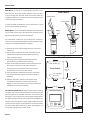
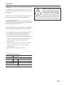
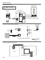
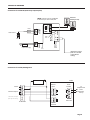
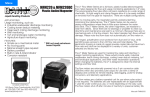
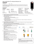
FT400-Series • FT415 • FT420 ISO 9 0 0 1 : 2 0 0 8 CERTIFIED COMPANY F T 4 0 0 - S E R I E S R AT E T O TA L / I N D I C AT O R I N S T R U C T I O N S RATE/TOTAL INDICATOR INSTRUCTIONS TABLE OF CONTENTS General Information General Information, Features, Specifications................................................................................................... Page 1 Installation Wall Mount, Meter Mount, Panel Mount............................................................................................................ Page 2 Connections, FT420 Option 98, -98 Relay Board Specifications...................................................................... Page 3 Connection Diagrams FT415, FT420, FT420-65.................................................................................................................................... Page 4 FT420-98, FT420/EX Magmeter........................................................................................................................ Page 5 FT420/EX Magmeter/Dual Power Supply (-27 Option)..................................................................................... Page 6 (Quick) Settings Quick Settings Overview...................................................................................................................................... Page 7 Settings K-Factor, Reading in Other Units......................................................................................................................... Page 8 Set K, Set P/Flow Alarm, Set 20 mA, Set Decimal Point, Set Time Unit.......................................................... Page 8 Operation Resettable Totalizer; 4-20 mA Output, Pulse Output, FT415 Battery Change................................................. Page 9 Troubleshooting Problems, Probable Causes, to Try...............................................................................................................Back Page TABLES AND DIAGRAMS Features, Specifications...................................................................................................................................... Page 1 Meter Mount, Panel Mount................................................................................................................................. Page 2 Dual Relay Board (Option -98) Specifications.................................................................................................... Page 3 Connections: FT415, FT420, FT420-65............................................................................................................. Page 4 Connections: FT420-98, FT420/EX Magmeter.................................................................................................. Page 5 Connections: FT420/EX Magmeter/Dual Power Supply................................................................................... Page 6 Quick Settings Overview...................................................................................................................................... Page 7 K-Factor................................................................................................................................................................. Page 8 Resettable Totalizer............................................................................................................................................. Page 9 Troubleshooting Problems, Probable Causes, to Try....................................................................................Back Page GENERAL INFORMATION The FT400-Series flow computers are microcontroller-based indicator/transmitters that display flow rate and total and provide output signals. The FT415 is battery-powered and provides a scalable pulse output. The FT420 is powered by external DC voltage and has both pulse and 4-20 mA analog outputs. When the FT420 is being used in the 4-20 mA mode, it is a “two-wire” or “loop-powered” device, meaning that the 4-20 mA output signal doubles as its power supply. The addition of a dual-relay output board (FT420 only) allows for certain applications requiring contact output isolation (e.g., certain metering pumps and water treatment controls). Dual solid state relays provide exactly the same pulse output as the standard unit, and each can signal one external device. A nonresettable total is also available. The FT420 can be ordered in a plastic enclosure with a 115 Vac power supply for use with mechanical meters, or with a built-in 115 Vac/12-24 Vdc dual power supply for magmeters. Both the FT415 and the FT420 can be factory-mounted on the meter (-M) or remotely wall mounted with the brackets provided (-W). The FT420 is also available as a panel mount (-P) with an open back for easy installation in the user’s own electrical enclosure. Most FT400’s can be converted from wall-to-meter or meter-to-wall mount configurations after installation if needed. Housings for the -W and -M models are rugged cast aluminum, potted and gasketed for maximum environmental protection. A membrane keypad allows settings to be changed without removing the cover. (Password protection, a standard feature, can be used to prevent settings from being changed.) **Includes password protection for tamper prevention when needed FEATURES Electronics Module Display Setup Keys** Cover Screws Lower Housing Strain Relief Wall-Mount Brackets SPECIFICATIONS* Power FT415 **Includes password protection for tamper prevention when needed FT420 Lithium "C", 3.6 Vdc, replaceable, 3-5 year life 12-30 Vdc, 4mA (4-20 mA when loop-powered) Display Rate 6-digit autorange, 1/2" character height 6-digit autorange, 1/2" character height Total 8-digit, 5/16" character height 8-digit, 5/16" character height Outputs Current Sinking Pulse Scaled Pulse output (0.1 sec duration 6.1 Hz max) (or High Alarm output or Low Alarm output) Sensor pass-through Pulse output (unscaled) Analog Pulse Output Range None 4-20 mA loop; 24-30 Vdc 0.1 - 9999999.9 units/pulse 0.1 - 9999999.9 units/pulse Input Micropower GMR Sensor (square wave) 5V pulse or contact closure Input Range 1.0 - 150 pulses/second 1.0 - 1,500 pulses/second K-Factor Range .001 - 99999.999 .001 - 99999.999 Flow Alarm Output Range .01 - 999999.99 .01 - 999999.99 Operating Temperature -30˚ to 65˚ C (-22˚ to 148˚ F) -30˚ to 65˚ C (-22˚ to 148˚ F) Environmental NEMA 4X, IP66 NEMA 4X, IP66 *Specifications subject to change • Please consult our website for current data (www.seametrics.com). Page 1 INSTALLATION Wall Mount. To mount an FT400-Series indicator to the wall, hold the unit in the desired position, mark the holes in the mounting feet, drill and mount with screws. With the FT420W-65 option, first remove the front cover to gain access to the mounting screw holes. Meter Mount Sensor Wires Sensor Wires A meter-mounted FT400-Series can be converted to a wall mount using an MK20 mounting kit. Meter Mount. If the FT400-Series indicator was ordered as an -M model, the housing is already directly mounted to the flow sensor and needs no further installation. An FT400-Series module can be converted from a wall-to a meter-mount using the MK10 adapter kit that includes a lower housing and associated hardware as follows: 1) Remove the strain relief through which the flow sensor cable runs. 2) Cut the cable to about 6” in length. Carefully strip the cable jacket to expose the three colored wires (red, white, and black) inside. 3) Route the wires through the threaded connector pre-installed in the bottom of the housing. 4) Start the threaded connector into the female thread on the top of the flow sensor. Be sure to match the oblong shape on the bottom of the housing to the depression on the top of the flow sensor. 5) Using an ordinary screwdriver inserted in one side of the slot (see drawing), tighten the screw as much as possible. 6) Strip the wire ends, make the connections to the FT400-Series indicator as shown in Connections Diagrams, and then use the cover screws to attach the indicator to the top of the housing. Panel Mount (FT420 Only). Using the “Panel Cutout” drawing as a guide, cut a square hole in the panel. Remove the clamps from the back of the FT420P and insert the indicator unit through the cutout, taking care that the panel sealing gasket is in place between the front of the panel and the flange of the indicator. Hold the indicator in place while starting the screw of one of the two clamps. Finger tighten the screw, then install the other clamp. When both are in place, firmly tighten the clamps with a small wrench or nut driver. Panel Mount R .38 Max, Typ. Panel Cutout 3.620 +.03/-.00 Typ .70 x .18 Clamp Area, Typ .36 .20 Max. Panel Thickness 1.50 3.85 typ. SET Gasket Page 2 INSTALLATION Connections. To connect the FT400-Series flow computer to a flow sensor or an external device such as a chemical metering pump, follow the Standard Connections diagrams on pages 4-6. If the FT420's 4-20 mA current signal is not required, connect the power terminals to any 12-30 Vdc voltage source. Caution: If output is being used to control an external device, such as a metering pump, do not connect the device until programming is completed. If malfunction or incorrect programming of the output could cause personal injury or property damage, separate safeguards must be installed to prevent such injury or damage. Dual Relay Output (Option -98). If you purchase the FT420 with option 98, the required component will come preinstalled, and no extra procedures are required. If you are retrofitting an existing installation of an FT420 with the dual relay board, please follow the instructions below: 1) 2) 3) 4) Peel the backing off of the double-stick tape and affix it to the bottom of the relay board (part #30221). Carefully attach the board to the FT420 as shown in the FT420-98 Connection diagram on page 5. Be sure that the red wire faces the “Sensor Input” side of the FT420, and that the white wire faces the “Pulse Output” side. Connect the white wire to the “Pulse Scaled” positive terminal, and the red wire to the “Power 4-20 mA” positive terminal. Connect devices to the relays as desired. -98 Relay Board Specifications Output Voltage 0-130 VAC/DC Output Current (each output) Temperature 50˚ C 85˚ C Current Limit 100 mA 50 mA Max Pulses/Second 5 Contact Time Per Output 100 ms Page 3 CONNECTION DIAGRAMS FT415 Standard Connections Pulse Responsive Metering Pump Caution: Do not apply external power to the FT415. Current sinking polarity-sensitive - + Outputs Pulse Passthru Pulse Scaled Battery Type: Lithium "C, 3V, replaceable Micropower Sensor + - Connections for FT420/3-Wire Mechanical Meter - PULSE SCALED Pulse Responsive Metering Pump + - Current sinking polarity-sensitive + - - 12-32 VDC Loop Power Supply* - PULSE PASSTHRU + + POWER 4-20 mA + + S 3-Wire Flow Sensor Mechanical Meter BASIC CONNECTIONS SENSOR INPUT Red White Black (Passes flow sensor pulse on to another control without scaling) - + Sensor Inputs Red White Black 4-20 mA Device (Passes flow sensor pulse on to another control without scaling) *FT420 ONLY Connections for FT420-65 (115 Vac Option) - + POWER 4-20 mA + - DC OUT FT420 AC IN Page 4 115 Vac GROUND NEUTRAL HOT LINE Lower Housing CONNECTION DIAGRAMS Connections for FT420-98 (Dual Relay Output Option) Electronic Metering Pumps NOTE: Outputs may be paralleled to switch up to 200 mA AC/DC - + - PULSE PASSTHRU - - 12-32 Vdc Loop Power Supply POWER 4-20 mA + + Relay Board white wire + Isolated Contact PULSE SCALED - 30221 S Flow Sensor + SENSOR INPUT Red White Black red wire (Passes flow sensor pulse on to another control without scaling) Connections for FT420/EX Magmeter _ Power + _ 24 Vdc Power + FT420 Sensor Input Pulse Scaled + S _ Forward Output + _ + _ + _ Reverse Output (EX Opt-15 only) EX SERIES + _ To Proportional Feed Metering Pump Pulse Pass-Thru Power 4-20mA Page 5 CONNECTION DIAGRAMS FT420 Display with 4-20 mA Output When running the FT420 with a magmeter (which requires power), the FT420 must be connected to two power supplies, one for the magmeter and one for the 4-20 mA loop. You may either use a dual power supply (available from Seametrics as the PC42), or two single power supplies (one of which may be the 4-20 mA loop itself). See diagrams below. Caution: Important! Do not connect power to the power supply until all connections have been made and confirmed correct, and the cover has been put back into place. FT420/4-20 mA Output with Two Separate Power Supplies Power + _ _ 24 Vdc Power + Pulse Scaled Sensor Input + S _ Forward Output + _ _ Reverse Output (Option-15 only) EX-SERIES 24 Vdc Power _ + _ + _ + + _ + Pulse Pass-Thru Power 4-20mA FT420 4-20 mA Device (e.g. pump, PLC) FT420/4-20 mA Output with PC42 Dual Power Supplies Caution: It is essential for safety and proper operation to use a ground connection for the 115 Vac power. Do not use this power supply without proper grounding. PC42 Dual Power Supply 4-20 mA Device Analog Output + PWR SW G AC AC 12V 24V +- +- FT420 Display Module + S (N/C) Earth Ground AC AC 100 mA Max Page 6 Sensor Input + EX80/EX100 Series Magmeter + + - 350 mA Max Pre-wired power cord Replace if required 115Vac, 50/60Hz Power Input (N/C) (N/C) Power Input Pulse Output (QUICK) SETTINGS QUICK SETTINGS OVERVIEW See following page for step-by-step instructions on changing these settings Pass through all settings and return to original display to save settings. PRESS DISPLAY 0.00 209.8 MIN Large digits display instantaneous flow rate (GPM). Small digits display total flow (since last reset). RESET START UP DISPLAY SET SET K SET 00001.000 0000010.0 SET P SET 0001000.0 SET 20 d SET SET 209.8 MIN K is the number of pulses the flow sensor provides for every gallon of flow. Find it on the fitting (80-Series) or chart (100/200-Series) or on the Seametrics website. P is the number of gallons per pulse desired on the scalable pulse output. (Example: P=1 is one pulse per gallon.) Skip without changing if you are not using the pulse output. 20 is the 20 mA maximum analog output. Set the flow rate you want to match maximum output. Example: 250 gpm maximum expected flow, “set 20” to 250. The analog output will scale to 4 mA at zero flow, 20 mA at 250 gpm*. This setting appears on the FT420 ONLY. d is the decimal point. It toggles back and forth with the . Set as many decimal places as needed. For higher flows, no decimal allows maximum number of whole digits. MIN is the time base, for example, gallons per minute. Use the to select sec/min/hour/day. *NOTE: Use the up arrow key to reach your desired digit. Then press the left arrow key to move to the next digit. Repeat the process until the entire number is entered. Page 7 SETTINGS K-FACTOR At a minimum, every FT400-Series flow computer must be programmed with the “K-factor”. (This is the number of pulses that the meter produces per gallon of flow.) If you wish the FT400 to read in units other than gallons, see below. The K-factor on any Seametrics flow sensor fitting or in-line meter can be found on the model-serial label. The line reading K = xxxx gives the desired number. For depth-adjustable sensors (101,201,115,215 models), use the calculator on our website. 80-Series Fixed Depth Meter 10031295 K: 53.6 Find Your K-Factor Here READING IN OTHER UNITS Changing Volume Units. The default K-factor units are pulses per gallon. To read your total in metric or other units instead, the standard K-factor must be converted to the desired volume units. For example, to read in pulses per liter, the K-factor must be multiplied by the applicable number shown below. NOTE: Both rate & total will read in whatever units you choose. Multiply by: .26418 264.18 .0078 7.48 Changing Time Units: To read your rate in liters per second (for example), convert the K-factor volume units as shown above and change the time units to Seconds, using the Set Time Unit instructions at right. Page 8 Set P/Flow Alarm. At this screen you may select between pulse output (P) or flow alarm (A) functions. If the pulse output and flow alarm features are not being used, this step can be skipped. The P (pulse output) setting does not affect anything if it is not being used. Set P is the default that appears on a new FT400-Series. On an FT400 that has been previously set up with flow alarm function, an A will appear on this screen. To move between P and A screens, firmly press all three keys for 5-10 seconds, then use the up arrow to scroll through the three options: P, AL HI (high flow alarm) and AL LO (low flow alarm). Set P. From this screen, follow the same process as for Set K to enter the desired pulse rate. This is the number of gallons (or whatever units are programmed) between pulses. (Note: Using the pulse output function disables the high and low flow alarm functions.) (6.1 Hz max output) MF81T-P200 To Convert K to: Liters Cubic Meters Fluid Ounces Cubic Feet Set K. Begin by pressing the SET key once. The prompt SET K should appear on the display. The digit to the far right will be blinking. Use the up arrow key to reach your desired value. Then press the left arrow key to move to the next digit. Repeat the process until the entire number is entered. (Note that the decimal is fixed at three places. If you only have two decimal places for your Kfactor, enter a zero for the third digit.) Press SET to advance. (Note: If unable to set K-factor, the unit is "locked" to prevent tampering. Please contact your Distributor for assistance.) Set Flow Alarm. From the A screen, use the up arrow key to choose either AL HI or AL LO and then press the SET key to set the alarm rate. Use the up arrow and left arrow as above to reach the desired digits. (Note: Using the flow alarm function disables the pulse output function.) Set 20 mA (FT420 Only). Press the SET key to advance to SET 20, to set the flow rate, in volume units per time unit, at which 20 mA is desired. Use the up arrow key to reach your desired value. Then press the left arrow key to move to the next digit. Repeat the process until the entire number is entered. The processor will automatically scale the 4-20 mA loop accordingly, with 4 mA at zero flow. Set Decimal Point. Press the SET key again for the D prompt. Pressing the up arrow key switches among no decimal place, one decimal place and two decimal places. Set Time Unit. When the SET key is pressed again, a blinking time unit appears. Press the up arrow key to select SEC (seconds), MIN (minutes), HR (hours) or DAY (days) (for example, gal/min, or gal/hr). To save settings and return to normal operation after entering settings, press SET again. When the unit is connected to an operating flow sensor, the rate (larger digits) and total (smaller digits) indicator numbers should appear in the display. OPERATION Resettable/Non-Resettable Totalizer. Unless the unit has been ordered with the non-reset option, a RESET prompt is visible in the lower right corner above the up arrow key, when the display is in use. Press the up arrow key at any time to reset the totalizer to zero. (Note: If you need to reset a unit that has been ordered with a non-resettable totalizer, contact your distributor.) (either standard electronic or relay-type), it should pulse for 0.1 second every time the set number of gallons has been totalized. If a pulse-responsive metering pump is properly connected to this output, it should stroke periodically. If this does not occur, see Troubleshooting, back page. FT415 Battery Change. The expected average life of the battery ranges between 3-5 years depending on the frequency of the input. The battery is easily pulled and replaced. When the battery is removed, all of the settings will be retained. SEC MIN HR DAY 1234.1 123456.7 RESET SET SEC MIN HR DAY SET This key resets total to zero when in normal run mode. CAUTION: During a battery change, the totalizer will reset to a previous total, which represents the last auto-backup (auto backups occur at approximately 4 minute intervals). If it is necessary to save the exact current total at the time of the battery change, save before removing the battery as follows: 1) Simultaneously press the SET and up arrow keys 2) Press SET again 3) Again simultaneously press the SET and up arrow keys CAUTION: Do not touch up Arrow button unless you intend to RESET Total to Zero. TOTAL IS NOT RECOVERABLE. Operation of 4-20 mA Output (FT420 Only). If the 4-20 mA output is in use and is correctly connected, the signal should vary between 4 mA and 20 mA in proportion to the flow, with the top flow rate set by the user (see Settings, page 8). At no time should the signal drop below 4 mA. A reading between 0 and 4 mA indicates a fault of some type, typically in the loop power supply or the connections (see Troubleshooting, back page). In the rare instance that the 4-20 signal fluctuates excessively (“paints”) it may need to be damped by additional averaging. Contact Seametrics for information on how to increase filtering. Operation of the Pulse Output. If the pulse output is being used Page 9 TROUBLESHOOTING Probable Cause Problem Try... Display blank No power to the unit Check for minimum 12 Vdc at power terminals Short in sensor circuit Disconnect sensor, see if display returns (zero flow rate) Battery dead or loose (FT415 only) Wiggle battery, replace if over three years old Display missing segments Damaged display module Contact distributor for return/replacement Display reading meaningless Unit’s microcontroller crashed characters Disconnect and reconnect power, if problem repeats, contact distributor for return/replacement Replace battery if over three years old Battery nearly dead Display reads normally, Wrong K-factor or time base entered flow rate incorrect Enter correct K-factor from meter, fitting, or manual Display reads normally, incorrect pulse output Wrong pulse output setting Use “Set P” to correct pulse output setting Polarity reversed on pulse output terminals Reverse leads Display reads normally, but Wrong 20 mA setting no (or incorrect) 4-20 mA output (FT420 only) Inadequate loop power supply voltage Use “Set 20” to correct target top flow rate Compare to Connections diagram Polarity incorrect in 4-20 mA loop circuit Check voltage (For 4-20 mA applications, 24 Vdc recommended) Display reads zero when Flow sensor failed there is flow Break in flow sensor circuit Flow sensor not battery-compatible Display reads flow rate when Long flow sensor wire, running parallel to there is none power wires Consult flow sensor manual for how to test Flow sensor malfunction See flow sensor manual to check Flow “jitter” (oscillating slosh) reads as flow Consult factory for “anti-jitter” setting Check for continuity with multimeter Check flow sensor model number for “micropower option” Reroute wire or change to shielded wire S e am e t r i c s In c o r po r at e d • 1 9 0 2 6 72n d A ven ue South • Ken t, W ashi n g ton 98032 • USA ( P ) 2 5 3 . 8 7 2 . 0 2 8 4 • ( F ) 2 5 3 . 8 7 2. 0285 • 1. 800. 975. 8153 • w w w . seametr i cs. com LT-65200063-D 9/20/10