1
ICP DAS WISE
User Manual
for WISE-580x Series
[Version 1.30]
ICP DAS WISE User Manual
Warning
ICP DAS Inc., LTD. assumes no liability for damages consequent to the use of
this product. ICP DAS Inc., LTD. reserves the right to change this manual at any time
without notice. The information furnished by ICP DAS Inc. is believed to be accurate
and reliable. However, no responsibility is assumed by ICP DAS Inc., LTD. for its
use, or for any infringements of patents or other rights of third parties resulting from
its use.
Copyright and Trademark Information
© Copyright 2009 by ICP DAS Inc., LTD. All rights reserved worldwide.
Trademark of Other Companies
The names used for identification only maybe registered trademarks of their
respective companies.
License
The user can use, modify and backup this software on a single machine. The user
may not reproduce, transfer or distribute this software, or any copy, in whole or in
part.
http://wise.icpdas.com
2
ICP DAS WISE User Manual
Table of Contents
1
2
3
4
5
Introduction ............................................................................................................ 9
Before Connection ............................................................................................... 14
2.1
Network configuration ............................................................................. 14
2.2
I-7000 Module Parameter Settings .......................................................... 16
WISE Web Page Overview .................................................................................. 19
3.1
Logic Setting Page ................................................................................... 19
3.2
Channel Monitoring Page ........................................................................ 22
Basic Setting ........................................................................................................ 24
4.1
Name Setting ............................................................................................ 24
4.2
Time Setting ............................................................................................. 24
4.3
Communication Setting ........................................................................... 26
4.4
Password Setting ...................................................................................... 27
4.5
XW-Board Setting .................................................................................... 28
4.6
I-7000 Modules Setting............................................................................ 34
4.7
Modbus RTU Modules Setting ................................................................ 39
Advanced Setting ................................................................................................. 54
5.1
5.2
5.3
5.4
5.5
5.6
5.7
5.8
5.9
Internal Register Setting .......................................................................... 54
Timer Setting............................................................................................ 55
Schedule Setting....................................................................................... 56
Email Setting............................................................................................ 59
CGI Command Setting ............................................................................. 61
Recipe Setting .......................................................................................... 62
Data Logger Setting ................................................................................. 64
Active I/O Setting .................................................................................... 66
SMS Setting ............................................................................................. 70
6
Rules Setting ........................................................................................................ 76
6.1
IF Condition ............................................................................................. 78
6.2
THEN/ELSE Action................................................................................. 89
6.3
Summary of the Rules ............................................................................ 101
6.4
Rule Manager ......................................................................................... 102
7 Download to Module ......................................................................................... 105
8 Upload from Module .......................................................................................... 106
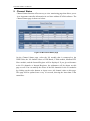
9 Channel Status.................................................................................................... 107
10 Firmware Update ............................................................................................... 108
10.1
10.2
Introduction ............................................................................................ 108
Install / Uninstall WISE Firmware Uploader ......................................... 108
http://wise.icpdas.com
3
ICP DAS WISE User Manual
10.3 Update WISE firmware .......................................................................... 111
Appendix I:Modbus Address Table ......................................................................... 115
Appendix II:Reset to Factory Default Setting......................................................... 132
http://wise.icpdas.com
4
ICP DAS WISE User Manual
List of Figures
Figure 1-1:WISE-580x System Architecture .............................................................. 9
Figure 1-2:WISE-580x IO module support list......................................................... 11
Figure 2-1:The Init Switch on the controller ............................................................ 14
Figure 2-2:Select “Search” function on MiniOS7 Utility ......................................... 14
Figure 2-3:IP Setting button on MiniOS7 Scan ........................................................ 15
Figure 2-4:Network Settings page ............................................................................ 15
Figure 2-5:I-7000 module connection via RS-485 line ............................................ 16
Figure 2-6:Check COM port, Baudrate, and DCON Protocol settings ..................... 17
Figure 2-7:I-7000 module Search ............................................................................. 17
Figure 2-8:I-7000 module configuration window ..................................................... 18
Figure 3-1:Main page of the Logic Setting page ...................................................... 19
Figure 3-2:Login page of the Logic Setting page ..................................................... 20
Figure 3-3:After login the Logic Setting page .......................................................... 20
Figure 3-4:WISE-580x Logic Setting Operation Procedures ................................... 21
Figure 3-5:The Channel Monitoring page (before login) ......................................... 22
Figure 3-6:The Channel Monitoring page (after login) ............................................ 22
Figure 3-7:Login into the Channel Monitoring page as Administrator .................... 23
Figure 3-8:Login into the Channel Monitoring page as Guest ................................. 23
Figure 4-1:Name Setting page .................................................................................. 24
Figure 4-2:The Name location on WISE Web Page ................................................. 24
Figure 4-3:Time setting page .................................................................................... 25
Figure 4-4:Communication setting page ................................................................... 26
Figure 4-5:Password setting page ............................................................................. 27
Figure 4-6:XW-Board setting page ........................................................................... 28
Figure 4-7:XW-Board DI attribute setting page ....................................................... 29
Figure 4-8:XW-Board DO attribute setting page ...................................................... 30
Figure 4-9:XW-Board AI attribute setting page ........................................................ 31
Figure 4-10:AI Deadband Operation(> or >= a numerical value) ............................ 32
Figure 4-11:AI Deadband Operation(< or <= a numerical value) ............................ 32
Figure 4-12:AI Deadband Operation(= a numerical value) ...................................... 33
Figure 4-13:XW-Board AO attribute setting page .................................................... 33
Figure 4-14:I-7000 module setting page ................................................................... 34
Figure 4-15:I-7000 modules list................................................................................ 35
Figure 4-16:I-7000 module DI attribute setting page ............................................... 36
Figure 4-17:I-7000 module DO attribute setting page .............................................. 37
Figure 4-18:I-7000 module AI attribute setting page................................................ 38
http://wise.icpdas.com
5
ICP DAS WISE User Manual
Figure 4-19:I-7000 module AO attribute setting page .............................................. 39
Figure 4-20:Modbus RTU Slave Module Setting Page ............................................ 40
Figure 4-21:Modbus RTU Slave Module List .......................................................... 42
Figure 4-22:Modbus RTU Slave Module Coil Output Setting Page ........................ 43
Figure 4-23:Modbus RTU Slave Module Coil Output Setting Example .................. 44
Figure 4-24:Modbus RTU Slave Module Discrete Input Setting Page ..................... 45
Figure 4-25:Modbus RTU Slave Module Discrete Input Setting Example .............. 47
Figure 4-26:Modbus RTU Slave Module Input Register Setting Page ..................... 48
Figure 4-27:Modbus RTU Slave Module Input Register Setting Example .............. 50
Figure 4-28:Modbus RTU Slave Module Holding Register Setting Page ................ 51
Figure 4-29:Modbus RTU Slave Module Holding Register Setting Example.......... 52
Figure 5-1:Internal Register setting page .................................................................. 55
Figure 5-2:Timer setting page ................................................................................... 56
Figure 5-3:Schedule setting page .............................................................................. 57
Figure 5-4:Schedule Calendar setting page .............................................................. 58
Figure 5-5:Email setting page ................................................................................... 59
Figure 5-6:Email encoded string setting ................................................................... 60
Figure 5-7:CGI Command setting page .................................................................... 61
Figure 5-8:Recipe setting page ................................................................................. 62
Figure 5-9:Recipe Action Management .................................................................... 62
Figure 5-10:Data Logger setting page ...................................................................... 64
Figure 5-11:Active I/O Setting page ......................................................................... 67
Figure 5-12:I/O Data Table configuration UI ........................................................... 67
Figure 5-13:The I/O Data Table for ”Coil and Register” type .................................. 68
Figure 5-14:The I/O Data Table for ”Register(Merge Coil into Register)” type ...... 69
Figure 5-15:Attribute of “Active I/O Data Sending” ................................................ 70
Figure 5-16:SMS Command Data Retrieve Coding Rules ....................................... 71
Figure 5-17:SMS Setting Page .................................................................................. 73
Figure 5-18:SMS Quick Command Setting Page ..................................................... 74
Figure 6-1:Rules setting page ................................................................................... 76
Figure 6-2:Enable rules, edit rules and status display ............................................... 76
Figure 6-3:Rule setting page ..................................................................................... 77
Figure 6-4:AI condition setting page ........................................................................ 78
Figure 6-5:DI condition setting page ........................................................................ 80
Figure 6-6:DI Counter condition setting page .......................................................... 81
Figure 6-7:Discrete Input condition setting page ...................................................... 81
Figure 6-8:Coil Output condition setting page ......................................................... 82
Figure 6-9:Input Register condition setting page ...................................................... 83
http://wise.icpdas.com
6
ICP DAS WISE User Manual
Figure 6-10:Holding Register condition setting page ............................................... 83
Figure 6-11:Internal register condition setting page ................................................. 84
Figure 6-12:Timer condition setting page ................................................................. 85
Figure 6-13:Schedule condition setting page ............................................................ 86
Figure 6-14:Rule Status condition setting page ........................................................ 87
Figure 6-15:SMS Command setting page ................................................................. 87
Figure 6-16:”One-Time Action” &”Repeat Action” Items ....................................... 90
Figure 6-17:AO action setting page .......................................................................... 90
Figure 6-18:DO action setting page .......................................................................... 91
Figure 6-19:DI Counter action setting page .............................................................. 92
Figure 6-20:Coil Output action setting page ............................................................. 92
Figure 6-21:Holding Register action setting page .................................................... 93
Figure 6-22:Internal Register action setting page ..................................................... 94
Figure 6-23:Timer action setting page ...................................................................... 95
Figure 6-24:Schedule action setting page ................................................................. 96
Figure 6-25:Email action setting page ...................................................................... 96
Figure 6-26:CGI Command action setting page ....................................................... 97
Figure 6-27:Recipe action setting page ..................................................................... 97
Figure 6-28:Rule Status action setting page ............................................................. 98
Figure 6-29:Data Logger action setting page ............................................................ 99
Figure 6-30:SMS Alarm Action Setting Page ........................................................... 99
Figure 6-31:Clear/Save Rules ................................................................................. 101
Figure 6-32:Rule setting main page ........................................................................ 101
Figure 6-33:Rule Manager setting page .................................................................. 102
Figure 6-34:Rule Copy setting page ....................................................................... 102
Figure 6-35:Rule Reset setting page ....................................................................... 103
Figure 6-36:Rule Reorder setting page ................................................................... 103
Figure 6-37:Rule Swap setting page ....................................................................... 104
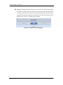
Figure 7-1:Remind the user to press the “Download to Module”........................... 105
Figure 7-2:Message showing a successful download ............................................. 105
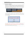
Figure 8-1:Message showing a successful upload .................................................. 106
Figure 9-1:Channel Status page .............................................................................. 107
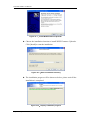
Figure 10-1:Install WISE Firmware Uploader ........................................................ 109
Figure 10-2:Select installation directory ................................................................. 109
Figure 10-3:Display installation progress ............................................................... 109
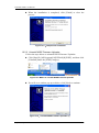
Figure 10-4:Complete the installation..................................................................... 110
Figure 10-5:Start to uninstall WISE Firmware Uploader ....................................... 110
Figure 10-6:Uninstall WISE Firmware Uploader (1) ............................................. 110
http://wise.icpdas.com
7
ICP DAS WISE User Manual
Figure 10-7:Uninstall WISE Firmware Uploader (2) ............................................. 111
Figure 10-8:Complete uninstalling WISE Firmware Uploader .............................. 111
Figure 10-9:Launch WISE Firmware Uploader ...................................................... 112
Figure 10-10:Select the WISE module type ........................................................... 112
Figure 10-11:Assign IP address .............................................................................. 113
Figure 10-12:Select the WISE firmware ................................................................. 113
Figure 10-13:Upload firmware ............................................................................... 113
Figure 10-14:Display firmware update progress(1) ................................................ 114
Figure 10-15:Display firmware update progress(2) ................................................ 114
Figure 10-16:Complete firmware update ................................................................ 114
http://wise.icpdas.com
8
ICP DAS WISE User Manual
1
Introduction
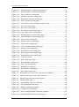
WISE-580x(Web Inside, Smart Engine) PAC Controller is an Intelligent Data Logger PAC
designed by ICP DAS that functions as control units for use in remote logic control
and monitoring in various industrial applications. WISE-580x offers a user-friendly
and intuitive HMI interface that allows you to implement control logic on controllers
just a few clicks away; no programming is required. With this powerful and
easy-to-use software, it will minimize the learning curve, shorten time to market and
dramatically reduce the labor and cost spent on system development.
Through Web browser, you can access Web Server on WISE-580x to perform tasks
such as logic rule edition and download. WISE-580x equips an IF-THEN-ELSE rule
engine that will check whether the rules are valid or not and determine the execution
of actions under specific conditions, for examples: setting up I/O channel values,
perform scheduled and Timer tasks, sending Email under a specific condition. In
addition, through the Modbus TCP Protocol, it enables SCADA software to control
and monitor I/O channel or system status on controllers in real time.
In addition to merits inherited from the previous WISE series, WISE-580x even
provides more supports in I/O functions. It allows to connecting with a wide range of
the XW-Board, I-7000 Remote I/O modules and Modbus RTU Slave modules;
enables to freely choose the most suitable I/O modules. With the microSD card, it
provides Data Logger function to real-time record the I/O data of the controller and
allows to send the data files by FTP or Email at a scheduled time to the control center
for further administration management or data analysis.
Figure 1-1:WISE-580x System Architecture
http://wise.icpdas.com
9
ICP DAS WISE User Manual
WISE- 580x system features:
IF-THEN-ELSE logic rules execution ability
WISE-580x equips with an IF-THEN-ELSE logic Rule Engine, it offers up to 36
IF-THEN-ELSE rules for you to set up the logic content. After completing rule
edition and downloading rules to the WISE controller, the Rule Engine will loop
execute the rules in order under specific conditions.
No programming is required to implement logic content on controllers
WISE-580x provides user-friendly Web UI pages for editing control logic on the
controllers. It enables to implement logic edition by a few clicks on the mouse to
set up and deploy logic rules without writing a single line of code.
No extra software tool is required; all operations can be done through the
Web browsers
Provides Web-based HMI interface runs on regular Web browsers. To edit
control logic, it only requires a browser to connect to the Web server on
WISE-580x. No extra software tool installation is needed on the target PC.
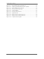
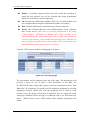
Support XW-Board and I-7000 I/O Module
WISE-580x allows to connecting with a wide range of the XW-Board and I-7000
Remote I/O modules that enables to find best solutions to meet the requirements.
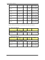
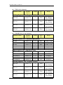
Please refer to the following table for I/O modules and functions (more to come
in near future):
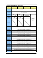
Functions
Modules
Voltage & Current
I-7012, I-7017
Thermocouple
I-7011, I-7018, I-7019
RTD
I-7013, I-7015, I-7033
Thermistor
I-7005
Transmitter
I-7014
Analog Output
I-7021, I-7022, I-7024
DC Digital Input
I-7041, I-7051, I-7052, I-7053
AC Digital Input
I-7058, I-7059
DC Digital Output
I-7042, I-7043, I-7045
DC Digital Input & Output
I-7044, I-7050, I-7055
Power Relay Output
I-7060, I-7061, I-7063, I-7065, I-7067
Solid State Relay Output
I-7063A/B, I-7065A/B
Photomos Relay Output
I-7066
Counter/Frequency
I-7080, I-7088
AI/AO
I-7000
Remote
I/O Module
DI/DO
Relay
Output
Others
http://wise.icpdas.com
10
ICP DAS WISE User Manual
DL Series
XW-Board
Temperature and Humidity
DL-100T485 (new)
DI/DO
XW-107、XW-110
DI/DO/AI/AO(Available Soon)
XW-304、XW-310
Figure 1-2:WISE-580x IO module support list
Support Modbus RTU Slave Module
In addition to XW-Board and I-7000 I/O modules, WISE-580x also allows to
connect with devices that support Modbus RTU Slave protocol for I/O
monitoring. The ability to connect with Modbus RTU Slave devices enables
flexibility and scalability for system implementation and allows to meet various
requirements from the clients.
Provide Timer and Schedule operation
WISE-580x features two kinds of timing functions: Timer and Schedule. It
allows you to perform specific tasks such as time delay, or schedule specific date
or time for control logic execution. To ensure the accuracy of the WISE
controller clock, it also has the ability to sync the clock to an SNTP time server
for time synchronization through the network.
Provide Email message and CGI command sending functions
WISE-580x supports Email message and CGI command sending functions.
Email and CGI command functions are important function for real-time message
communication. The sending action can be added to the logic edition as part of
logic control to provide real-time message transmission or sending CGI
command for device control in response to specific events.
Recipe function for Group Action operation
WISE-580x provides Recipe function that allows to execute a sequence of
actions previously saved in the Recipe to response to IF-THEN-ELSE logic rules
Conditions. You can create different Recipe sets to meet various requirements for
different applications.
Data Logger function
With the microSD card, WISE-580x provides Data Logger function to real-time
record the I/O data of the controller and sends the data files by FTP or Email to
the control center for further administration management or data analysis.
http://wise.icpdas.com
11
ICP DAS WISE User Manual
Real-time monitoring system status of controllers
WISE-580x supports Modbus TCP/RTU Protocol for you to perform real-time
monitoring and control of the controllers. Please refer to Appendix 1 for the
mapping table of controller system information and Modbus Address. In addition,
WISE provides an easy-to-view HMI web interface for real-time monitoring. It
allows you to get important real time system information even without SCADA
software.
Password protection for access control
WISE HMI web page offers password protection. After getting in the webpage,
you will be required to input the password before editing logic rules. In addition,
WISE-580x provides monitoring web pages specifically designed for cell phone.
The access control restricts the access to the webpage to prevent unauthorized
modification; it allows to set up passwords for guest and administrator; only the
authorized users will be allowed to modify the channel data.
Provides SMS command receiving function and alarm notification function
(Only apply to WISE-5801)
WISE-5801 equips SMS command receiving and alarm message notification
function. It allows to include SMS alarm sending action into logic rules to send a
pre-set SMS message to related personnel when an event occurs. In addition,
WISE-5801 allows to receive the SMS commands sending by specific phones
numbers to perform tasks such as real-time channel monitoring, channel data
modification and logic rules execution (triggered by SMS), etc.
Active I/O Sending function (New)
In addition to the Modbus TCP/RTU Slave function that enables SCADA
software (or HMI device) to poll the I/O channels value of the WISE controller,
now WISE-580x provide the new function “Active I/O Sending” for user. Based
on the “Active I/O Sending” function, WISE-580x can send the I/O channels
value of the controller actively to SCADA software (or HMI device) by event
trigger (I/O channel value changed) or periodic cycle. This function will improve
the efficient of the data communication between WISE-580x and SCADA
software (or HMI device). Please note: The SCADA software (or HMI device)
must equip the Modbus TCP Slave function to receive the I/O channels data sent
by WISE-580x.
http://wise.icpdas.com
12
ICP DAS WISE User Manual
This document is intended to give you a full-range instruction to WISE-580x
controllers. You will be able to learn how to edit logic of the rules and how to
download the rules to the controllers for conditional execution.
http://wise.icpdas.com
13
ICP DAS WISE User Manual
2 Before Connection
Before connecting to WISE-580x Web HMI pages, please complete the following
steps to implement network configuration and I-7000 modules parameter settings.
The procedures are as follow:
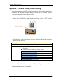
2.1 Network configuration
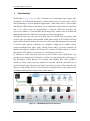
Please make sure the Init Switch on the controller has been switched to
“OFF” position. Connect the controller to power supply and to the
network. The Init Switch position is shown as below:
Figure 2-1:The Init Switch on the controller
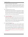
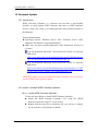
Install and execute MiniOS7 Utility. MiniOS7 Utility can be
downloaded from the following link. Please download version v3.2.4
or later.
http://ftp.icpdas.com/pub/cd/8000cd/napdos/minios7/utility/minios7_util
ity/
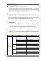
On toolbar, select ConnectionSearch (shown as below). A “MiniOS7
Scan” window will pop up and automatically start to search controllers
in the network.
Figure 2-2:Select “Search” function on MiniOS7 Utility
http://wise.icpdas.com
14
ICP DAS WISE User Manual
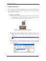
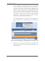
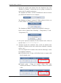
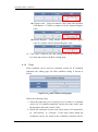
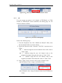
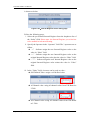
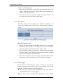
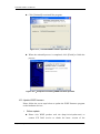
After finish searching, find the target controller and click “TCP
Broadcast”, and then click “IP Setting” button on the toolbar as shown
below:
Figure 2-3:IP Setting button on MiniOS7 Scan
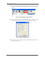
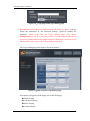
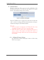
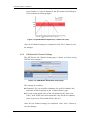
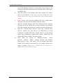
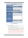
Click “IP Setting” button, a network settings window will pop up. Input
the information and click the "Set" button to complete the settings.
Figure 2-4:Network Settings page
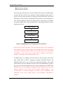
After finish Network settings, reboot the WISE-580x controller for the
changes to take effect.
http://wise.icpdas.com
15
ICP DAS WISE User Manual
2.2 I-7000 Module Parameter Settings
To access I/O data on I-7000 Modules, it is required to complete I-7000
module parameter settings before trying to communicate with I-7000
Modules. The I-7000 module parameter settings can be done by DCON
Utility.
You can download DCON Utility from the link below:
http://ftp.icpdas.com/pub/cd/8000cd/napdos/driver/dcon_utility/
And you can download DCON Utility manual from the link below:
http://ftp.icpdas.com/pub/cd/8000cd/napdos/driver/dcon_utility/manual/
Install the DCON Utility on PC and connect the I-7000 Module to the
PC for parameter settings, please follow the steps below (for more
detailed information, please refer to DCON Utility manual):
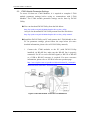
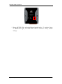
i.
Connect the I-7000 modules to the PC (with DCON Utility
installed) via RS-485 line, make sure the RS-485 line is properly
connected. For PC to receive RS-485 signals, a RS-232 to RS-485
or a USB to RS-485 converter is required. For more converter
information, please refer to ICP DAS converter product page:
http://www.icpdas.com.tw/product/solutions/industrial_communic
ation/converter/converter_selection.html
Figure 2-5:I-7000 module connection via RS-485 line
http://wise.icpdas.com
16
ICP DAS WISE User Manual
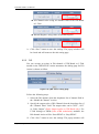
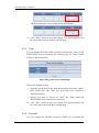
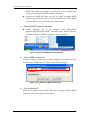
ii.
Start the DCON Utility and verify if the COM Port value is
accurate.
Figure 2-6:Check COM port, Baudrate, and DCON Protocol settings
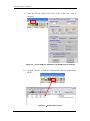
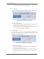
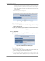
iii.
Perform “Search” to find all I-7000 modules that are connected to
the PC.
Figure 2-7:I-7000 module Search
http://wise.icpdas.com
17
ICP DAS WISE User Manual
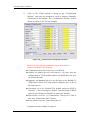
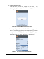
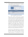
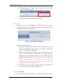
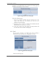
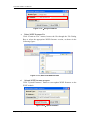
Click on the I-7000 module to bring up the “Configuration
Window” and setup the parameters (such as Address, Baudrate,
Checksum) for the module. The “Configuration Window” will be
shown as follow(I-7017Z as an example):
iv.
Figure 2-8:I-7000 module configuration window
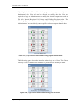
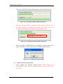
Please note: The following parameters has to be accurate to
connect with WISE-580x properly:
Communication Protocol: has to be set as DCON。
Address: the address has to be set between 1~16, please note: the
configuration of I-7000 module address on WISE-580x has to be
set exactly the same.
Baudrate: the Baudrate has to be set the same as the Baudrate of
WISE-580x COM2, all I-7000 modules’ Baudrate have to be set
the same as well.
Checksum: set to be “Disable”(The default setting on WISE is
“Disable”.). You can change to “Enable”, but the setting on WISE
also has to be changed to“Enable” to ensure this function.
Data format: set to be “2’s Complement” (Except for I-7024, it
only uses “Engineering Unit” format).
Parity Option: set to be ”None Parity(N,8,1)”。
Complete the other settings as required.
http://wise.icpdas.com
18
ICP DAS WISE User Manual
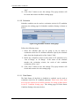
3 WISE Web Page Overview
WISE-580x equips v2.20(or later) firmware, it provides two web page interfaces:
Logic Setting page and Channel Monitoring page. The Logic Setting page allows to
perform logic setting on WISE controller. And the Channel Monitoring page allows to
monitor or modify the I/O channel data on WISE Controller.
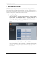
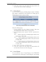
3.1 Logic Setting Page
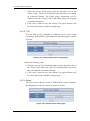
When you connect to WISE-580x by Web browser (IE, Firefox or Chrome
browser), WISE will automatically connect to the Logic Setting page. In
order to get a better operation experience, 1280x1024 resolution is
recommended. The Logic Setting page of WISE-580x controller is shown as
below:
Figure 3-1:Main page of the Logic Setting page
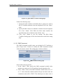
You will be required to enter the password to login into the page before
performing logic settings. The login section is on right upper corner, as
shown below:
http://wise.icpdas.com
19
ICP DAS WISE User Manual
Figure 3-2:Login page of the Logic Setting page
Both default passwords set for Administrator and Guest are “wise”. You can
follow the instruction in “4.4 Password Setting” section to modify the
password. Please note that the Logic Setting page only allows
Administrator to log in. If you only need to view the channel data, please
select the Channel Monitoring option under the “Web Page” selection. It will
automatically be directed to the Channel Monitoring page.
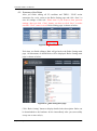
The Logic Setting page after login is shown as bellow:
Figure 3-3:After login the Logic Setting page
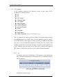
Six buttons will appear on the upper part of the Web page:
Basic Setting
Advanced Setting
Rules Setting
Channel Status
http://wise.icpdas.com
20
ICP DAS WISE User Manual
Upload from Module
Download to Module
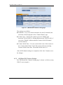
The main page will show the version of WISE-580x firmware (WISE Engine
Version), the OS version of the controller and the controller module name. A
list of I/O devices that currently are connected to the WISE-580x; such as the
XW-Board, I-7000 modules and Modbus RTU modules; will be displayed as
well. And the connection status will also be shown on this page. In addition,
the general WISE-580x Logic Setting Web UI operating procedures will be
displayed as follow:
Basic Setting
Advanced Setting
Rules Setting
Download to Module
Figure 3-4:WISE-580x Logic Setting Operation Procedures
Please note: DO NOT refresh or close the web page when you are editing the
rules, otherwise the contents of all previous settings will be gone. And please
remember all settings will take effect only when they have been downloaded
to modules, if you close the web page before finishing “Download to
Module”, all settings will be disappeared as well.
In addition, there is a language selection menu on the left region of the main
page. WISE Web UI offers 3 languages: English, Traditional Chinese and
Simplified Chinese for you to choose your preferred languages. The system
will memorize previous language selection, and will automatically switch to
the previously chosen language next time when connected to the WISE Web
UI. Please note: do not change the language setting during the process of rule
edition; otherwise the previous edited content might disappear. It is
recommended to perform language selection at the beginning when
connected to the Logic Setting page or after finishing “Download to
Module”.
http://wise.icpdas.com
21
ICP DAS WISE User Manual
3.2 Channel Monitoring Page
When you connect to WISE-580x controller by cell phone, it will
automatically being directed to the Channel Monitoring page, the Channel
Monitoring page is shown as below:
Figure 3-5:The Channel Monitoring page (before login)
You can input the password to get into the Channel Monitoring page or select
the “Go to Logic Setting page” to perform logic settings. After you login into
the page, it will show WISE-580x module name, and will list all I/O devices
currently connected to the WISE-580x; such as the XW-Board, I-7000
modules and Modbus RTU modules. The interface is shown as below:
Figure 3-6:The Channel Monitoring page (after login)
http://wise.icpdas.com
22
ICP DAS WISE User Manual
If you login into the Channel Monitoring page as a Guest, you can only view
the channel data. You will not be allowed to modify the data. You are
required to login as Administrator to modify the channel output data such as
DO, AO, Internal Register, Coil Output and Holding Register value. The
following figure shows the interface that will be displayed when login as an
Administrator. You can directly enter specific values to output channel data.
Figure 3-7:Login into the Channel Monitoring page as Administrator
The following figure shows the interface when login as a Guest. The Guest
can only view the channel data without the permission to modify the data.
Figure 3-8:Login into the Channel Monitoring page as Guest
http://wise.icpdas.com
23
ICP DAS WISE User Manual
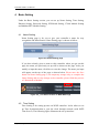
4 Basic Setting
Under the Basic Setting section, you can set up Name Setting, Time Setting,
Ethernet Setting, Password Setting, XW-Board Setting, I-7000 Module Setting
and Modbus RTU Module Setting.
4.1 Name Setting
Name Setting page is for you to give your controller a name for easy
recognition and identification. Name Setting page is shown as follow:
Figure 4-1:Name Setting page
If you have already given a name to this controller, when you get on this
page, the name you previously set up will be shown on the page. After you
modify or input the name, click Save to save the change. The name you input
will appear on the top of the page as shown below. Please note: the Save
button on Name Setting page is for temporary storage only, to complete the
Name Setting and save the change to the controller, please finish the process
of “Download to Module”.
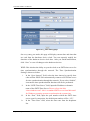
Figure 4-2:The Name location on WISE Web Page
4.2 Time Setting
Time Setting is for setting up time on WISE controller. It also allows to set
up Time Synchronization to sync the clock through network (with SNTP
Time Server). The following figure illustrates the set up interface:
http://wise.icpdas.com
24
ICP DAS WISE User Manual
Figure 4-3:Time setting page
On every entry you make, this page will display current date and time that
are read from the hardware device clock. You can remotely modify the
date/time of the hardware device clock here. After you finish modification,
click “Save” to save all changes to the hardware devices.
WISE-580x also has the ability to sync the clock to an SNTP time server for
time synchronization through the network. The Time Synchronization
Setting is shown as follow:
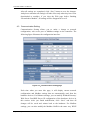
i. In the “Sync Interval” field, select the time interval to specify how
often will the WISE-580x automatically connect to SNTP time server
ii.
iii.
iv.
for time synchronization through the network. If you select “disable”,
it means the time synchronization function will not be performed.
In the “SNTP Time Server” field, input the IP address or domain
name of the SNTP Time Server. Please refer to the link:
“time.windows.com”- this is a standard SNTP server from Microsoft
for Windows operating system to synchronize the system time.
In the “Port” field, input the port number which the SNTP time
server open for connection, the default port number will be “123”.
In the “Time Zone” field, select the time zone from the dropdown
list.
http://wise.icpdas.com
25
ICP DAS WISE User Manual
After all settings are completed, click “Save” button to save the changes.
And please remember all settings will take effect only when they have been
downloaded to modules, if you close the Web page before finishing
“Download to Module”, all settings will be disappeared as well.
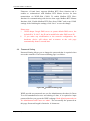
4.3 Communication Setting
Communication Setting allows you to make a change to network
configuration, web server port or Modbus settings on the controller. The
following figure illustrates the configuration interface:
Figure 4-4:Communication setting page
Each time when you enter this page, it will display current network
configuration and Modbus settings that are automatically read from the
hardware devices. For Ethernet settings, you can modify IP/Mask/Gateway/
Web Server Port/DNS Server IP configuration of the hardware devices in
this section. After you finish modification, click “Save” and then all
changes will be saved and written back to the hardware. For Modbus
settings, you can also modify the Modbus NetID in the same way. WISE
http://wise.icpdas.com
26
ICP DAS WISE User Manual
Firmware v2.1(and later) supports Modbus RTU Slave function and it
enables to communicate with Modbus RTU Master devices for data
transmission via WISE-580x COM1. To enable Modbus RTU Slave
function for communicating with devices that equip Modbus RTU Master
function; click “Enable Modbus RTU Slave from COM1” and set up COM1
settings. After finishing the settings, click “Save” to save the change.
Please note:
i.
WISE adopts Google DNS server as system default DNS server, the
ii.
default IP is ”8.8.8.8”, the IP can be modified to other DNS server IP.
If you make any modification to the network configuration, the
hardware device will reboot and re-connect to the web page
automatically about 5 seconds later.
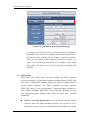
4.4 Password Setting
Password Setting allows you to change the password that is required when
access the controller. The Password Setting page is as follow:
Figure 4-5:Password setting page
WISE provide two passwords set, one for Administrator, the other for Guest.
To avoid unauthorized access and altering of data; it is required to input
password before you get on the WISE webpage. Both default passwords set
for Administrator and Guest are “wise”. You can modify the password on
this page. Password length is limited to 16 characters.
http://wise.icpdas.com
27
ICP DAS WISE User Manual
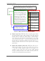
4.5 XW-Board Setting
XW-Board Setting page allows you to set up the configuration of the
XW-Board that connects to the WISE-580x and function as I/O control
interface. The XW-Board Setting is shown as follow:
Figure 4-6:XW-Board setting page
Select the XW-Board you are using from the drop down list and click
“Add”, a window for setting up XW-Board channel parameters will appear.
Complete the settings for each XW-Board channel.
Please note:
i. After you complete all configuration for XW-Board DI, DO, AI and
AO channels, remember to click “Save” to save the settings.
ii. WISE-580x allows to connect with one XW-Board only, however; it
allows to connect I-7000 modules and Modbus RTU modules via
RS-485 interface through COM2 at the same time when connecting to
the XW-Board.
4.5.1
XW-Board DI Channel Settings
The XW-Board DI Channel Setting page is shown as follow (using
XW107 as an example):
http://wise.icpdas.com
28
ICP DAS WISE User Manual
Figure 4-7:XW-Board DI attribute setting page
The settings are as follow:
Nickname:For you to define nicknames for each I/O channel, this
nickname will be displayed on the “Channel Status” page.
Counter Type:Specify the counter type to be “Falling edge
detection” (ON-to-OFF) or “Rising edge detection” (OFF-to-ON); if
you select “Disable” indicates that the counter of this DI channel
will not function.
Counter Initial Value:You can set the initial value of the counter in
the “Counter Initial Value” field. This counter will start counting
from the initial count value. The default initial value is 0.
After all DI channel settings are completed, click “Save” button to save
the changes.
4.5.2
XW-Board DO Channel Settings
The XW-Board DO Channel Setting page is shown as follow (using
XW107 as an example):
http://wise.icpdas.com
29
ICP DAS WISE User Manual
Figure 4-8:XW-Board DO attribute setting page
The settings are as follow:
Nickname: for you to define nicknames for each I/O channel, this
nickname will be displayed on the “Channel Status” page.
You can specify the initial status to be “ON” or to be “OFF” when
the WISE-580x is power on. Select the value from the dropdown list
of “Power On Value” field. The default value is “OFF”.
If you check the Enable pulse output checkbox, it will allow this DO
channel to perform pulse output and form a periodic pulse cycle. In
Pulse Output mode, the selected DO channel will generate a square
wave according to specified parameters (Pulse High and Pulse Low).
Pulse High and Pulse Low are required and has to be entered in
multiples of 10ms. Pulse High indicates the “ON” time duration and
Pulse Low indicates the “OFF” time duration in a periodic Pulse
cycle.
After all DO channel settings are completed, click “Save” button to
save the changes.
Please note: the DO channel of XW-Board does not offer Counter
function.
4.5.3
XW-Board AI Channel Settings
The XW-Board AI Channel Setting page is shown as follow (using
XW304 as an example):
http://wise.icpdas.com
30
ICP DAS WISE User Manual
Figure 4-9:XW-Board AI attribute setting page
The settings are as follow:
Nickname: For you to define nicknames for each I/O channel, this
nickname will be displayed on the “Channel Status” page.
In the “Scale” field, AI channel raw data can be set to operate with
linear proportion between “MIN” and “MAX” values. The IF
Condition will use the adjusted value in the logic Rule operation,
and the AI value retrieved from Modbus TCP and “Channel Status”
page would be the adjusted value. The default value for MAX and
MIN is 0, it means the Scale function is disabled.
Deadband: In order to avoid signal oscillation that may result in
instability to the status changes, you can set up a Deadband value
for the AI channel to reduce the oscillation effect to the channel
value. The AI attribute configuration page is shown as below:
There are three operation styles for AI Deadband. Detailed description
is as below. The AI Channel setting in following examples is 0mA ~
20mA.
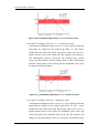
(a) In the IF Condition, when AI > or >= a numerical value:
Assuming the Deadband value is set to be 2 mA, and the following
statements are defined in the related logic Rule: IF AI0>10mA,
THEN DO=ON, ELSE DO=OFF, that means, when AI0 receives a
signal that exceed 10mA, the DO channel will change to ON
immediately, however, when the AI0 channel value drops and
becomes lower than 10mA, the DO channel will not change back to
OFF immediately until the value reaches 8mA (10mA minus the
Deadband value 2mA), as shown in following figure.
http://wise.icpdas.com
31
ICP DAS WISE User Manual
Figure 4-10:AI Deadband Operation(> or >= a numerical value)
(b) In the IF Condition, when AI < or <= a numerical value:
Assuming the Deadband value is set to be 2 mA, and the following
statements are defined in the related logic Rule: IF AI0<10mA,
THEN DO=ON, ELSE DO=OFF, that means, when AI0 receives a
signal which is lower than 10mA, the DO channel will change to
ON immediately, however, when the AI0 channel value exceed
10mA, the DO channel will not change back to OFF immediately
until the value reaches 12mA (10mA plus the Deadband value 2mA),
as shown in following figure.
Figure 4-11:AI Deadband Operation(< or <= a numerical value)
(c) In the IF Condition, when AI = a numerical value:
Assuming the Deadband value is set to be 1 mA, and the following
statements are defined in the related logic Rule: IF AI0 = 9mA,
THEN DO=ON, ELSE DO=OFF, that means, when AI0 receives a
signal between 8mA (9mA minus the deadband value 1mA) and
10mA (9mA plus the deadband value 1mA), the DO channel will
change to ON immediately. However, when the AI0 channel value
http://wise.icpdas.com
32
ICP DAS WISE User Manual
exceed 10mA, or is lower than 8mA, the DO channel will change to
OFF, as shown in following figure.
Figure 4-12:AI Deadband Operation(= a numerical value)
After all AI channel settings are completed, click “Save” button to save
the changes.
4.5.4
XW-Board AO Channel Settings
The XW-Board AO Channel Setting page is shown as follow (using
XW304 as an example):
Figure 4-13:XW-Board AO attribute setting page
The settings are as follow:
Nickname: For you to define nicknames for each I/O channel, this
nickname will be displayed on the “Channel Status” page.
You can set the initial value of the AO channel in the “Power On
Value” field. WISE-580x will output this value for the AO channel
when is power on. The default initial value is 0.
After all AO channel settings are completed, click “Save” button to
save the changes.
http://wise.icpdas.com
33
ICP DAS WISE User Manual
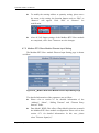
4.6
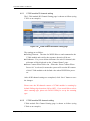
I-7000 Modules Setting
I-7000 Modules Setting page allows you to select the module types of the
I-7000 modules and DL-100T485 connecting to the WISE-580x via COM2
and enables to set up the configuration for each individual I-7000 module.
Each WISE-580x controller allows to connecting to up to 16 I-7000
modules. Module Address setting must be in the range 1~16. The I-7000
Modules Setting page is shown as below:
Figure 4-14:I-7000 module setting page
Follow the following steps:
In the “Baudrate” field, select the WISE-580x COM2 data
transmission rate from the drop down list.
In the “Checksum” field, specify the Checksum setting for the
communicate between WISE and I-7000 to be enabled or disabled.
The default setting is “Disable”.
In the “Auto Search” field, click on “Scan” button to search the
I-7000 modules that are connected to the controller via COM2.
Please note: to ensure a proper connection, make sure when you use
DCON Utility to set up the Baudrate and the checksum for each
I-7000 module, the Baudrate and the checksum have to be set the
same as WISE-580x settings(as previous setup) .
http://wise.icpdas.com
34
ICP DAS WISE User Manual
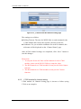
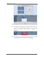
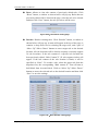
In addition to “Auto Search”, you can add the I-7000 module one
by one; complete “Module”, “Type”, “Address” and “Polling Time”
field and then click “Add” button to add a new I-7000 module. An
example of the I-7000 module list is shown as below:
Figure 4-15:I-7000 modules list
Select an I-7000 module and click on “Setting” button to edit
detailed parameters for each module. To remove the I-7000 module,
select the module you would like to remove and click “Remove”
button to remove the specific module. To relocate I-7000 to other
address, click “Move Up” or “Move Down” to move the I-7000
module to desired address.
After all I-7000 module settings are completed, click “Save” button
to save the changes
Please refer to the following sections for more detail on I-7000 module DI,
DO, AI and AO channel configurations.
Please note: currently WISE-580x only connect to I-7000 via COM2, please
make sure if the I-7000 modules are connected to WISE-580x COM2.
http://wise.icpdas.com
35
ICP DAS WISE User Manual
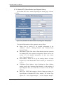
4.6.1
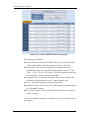
I-7000 module DI channel setting
The I-7000 module DI Channel Setting page is shown as follow (using
I-7052 as an example):
Figure 4-16:I-7000 module DI attribute setting page
The settings are as follow:
Polling Timeout:The time for WISE-580x to send command to the
I-7000 module and wait for the response, the unit will be ms.
Nickname:For you to define nicknames for each I/O channel, this
nickname will be displayed on the “Channel Status” page.
Reset Counter When Power On:When the “Reset Counter When
Power On” is selected, it means the system will reset the DI counter
of this I-7000 module to the default value when WISE-580x power
on.
After all DI channel settings are completed, click “Save” button to save
the changes.
Please note: the DI channel counter of I-7000 module is counting by
default Falling edge detection (ON-to-OFF), if you would like to select
other counting type, please use DCON Utility to set up the counting
type.
4.6.2
I-7000 module DO channel setting
I-7000 module DO Channel Setting page is shown as follow (using
I-7060 as an example):
http://wise.icpdas.com
36
ICP DAS WISE User Manual
Figure 4-17:I-7000 module DO attribute setting page
The settings are as follow:
Polling Timeout: The time for WISE-580x to send command to the
I-7000 module and wait for the response, the unit will be ms.
Nickname: For you to define nicknames for each I/O channel, this
nickname will be displayed on the “Channel Status” page.
After all DO channel settings are completed, click “Save” button to
save the changes.
Please note:
1. To setup the Power On Value on DO channel for each I-7000
module, please use the DCON Utility to setup the value.
2. The DO channels on I-7000 modules do not provide Pulse Output
function.
3. The DO channels on I-7000 modules do not provide Counter
function.
4.6.3
I-7000 module AI channel setting
I-7000 module AI Channel Setting page is shown as follow (using
I-7018 as an example):
http://wise.icpdas.com
37
ICP DAS WISE User Manual
Figure 4-18:I-7000 module AI attribute setting page
The settings are as follow:
Polling Timeout: The time for WISE-580x to send command to the
I-7000 module and wait for the response, the unit will be ms.
Temperature Unit: Specify temperature measurement unit for
modules that allows for temperature measurement, such as I-7005,
I-7011, I-7013, I-7015, I-7018 and I-7019, the temperature units can
be set as degree Celsius or degree Fahrenheit.
Nickname: For you to define nicknames for each I/O channel, this
nickname will be displayed on the “Channel Status” page.
Type:Select the appropriate AI signal input type.
Deadband: Please refer to section 4.8 XW-Board AI channel settings
for “Deadband” settings.
Scale: Please refer to section 4.8 XW-Board AI channel settings for
“Scale” settings.
After all AI channel settings are completed, click “Save” button to save
the changes.
http://wise.icpdas.com
38
ICP DAS WISE User Manual
4.6.4
I-7000 module AO channel setting
I-7000 module AO Channel Setting page is shown as follow (using
I-7024 as an example):
Figure 4-19:I-7000 module AO attribute setting page
The settings are as follow:
Polling Timeout: The time for WISE-580x to send command to the
I-7000 module and wait for the response, the unit will be ms.
Nickname: For you to define nicknames for each I/O channel, this
nickname will be displayed on the “Channel Status” page.
Type: Select the appropriate AO signal output type.
After all AO channel settings are completed, click “Save” button to
save the changes.
Please note: please use DCON Utility to set up the Power On Value for
each AO channel on I-7000 modules.
4.7 Modbus RTU Modules Setting
In addition to XW-Board and I-7000 I/O modules, WISE-580x also allows
to connect with devices that support Modbus RTU Slave protocol for I/O
control. Through Modbus RTU protocol, it enables to read back 4 types of
Modbus data (Coil Output, Discrete Input, Input Register and Holding
Register) from the Modbus RTU Slave modules to the WISE-580x. And by
WISE IF-THEN-ELSE rule engine, it allows to perform automation control
operation on the devices. And with SCADA software, it also allows to
monitor and control the Modbus RTU device retrieved information on the
WISE-580x.
http://wise.icpdas.com
39
ICP DAS WISE User Manual
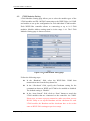
In Modbus RTU Modules Setting page, it allows to perform parameters
settings and related configuration of the Modbus RTU Slave modules for
use in the IF-THEN-ELSE rules edition. Each WISE-580x controller can
connect up to four Modbus RTU Slave Modules. The Modbus RTU address
range starts from 17 to 20. The setting page is shown as follow:
Figure 4-20:Modbus RTU Slave Module Setting Page
Follow the following steps:
i. In the “Baudrate(COM2)” field, select the WISE-580x COM2 data
transmission Baudrate from the drop down list. The Baudrate has to
be set the same as the Baudrate of Modbus RTU Slave modules.
Please note: on the I-7000 Module Setting page, there is a COM2
ii.
Baudrate setting as well, please note that all I-7000 modules and
Modbus RTU Slave modules that are connected to the WISE-580x
COM2 must be set to the same Baudrate.
Select the data transmission Baudrate for WISE-580x COM2, and
then the system will automatically provide a proper value in the
“Silent Interval” field. For each Modbus RTU Slave device has
different Modbus command process capability, the response time
for sending result from Modbus RTU Slave device to controller
might be different. User can adjust this value to most appropriate
time interval, such as: extend this value to make sure every Modbus
RTU Slave device connected to the WISE-580x has enough time to
http://wise.icpdas.com
40
ICP DAS WISE User Manual
iii.
iv.
v.
vi.
vii.
process the Modbus command, or shorten this value to improve the
efficient of the poll mechanism between Modbus RTU Slave device
and WISE-580x.
Select the address of the Modbus RTU Slave module. The address
has to be set between 17~20. Please note: the configuration of the
address must be the same as the Modbus RTU Slave module address
setting.
In the “Name” field, input the Modbus RTU Slave module name.
This name will be used in IF-THEN-ELSE rule edition.
Input the “Polling Timeout” field. The “Polling Timeout” indicates
the time interval for WISE-580x to send command to the Modbus
RTU Slave module and wait for the response, the unit is millisecond.
Input the “Timeout Retry Interval” field. The “Timeout Retry
Interval” indicates the time interval for WISE-580x to resend
command to Modbus RTU Slave module when it’s in the timeout
status when performing communication between WISE-580x and
Modbus RTU Slave module. The unit is second.
After finish the settings of ”Baudrate(COM2)”, “Silent
Interval”, ”Address”, “Name”, “Polling Timeout” and ”Timeout
Retry Interval”, click “Add” button. The new Modbus RTU Slave
module will be added to the module list. An example module list is
shown as bellow. Please note: a WISE-580x can connect to 4
Modbus RTU Slave modules at most.
http://wise.icpdas.com
41
ICP DAS WISE User Manual
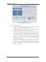
Figure 4-21:Modbus RTU Slave Module List
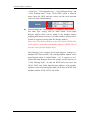
viii.
Click on the Modbus RTU Slave module on the module list and click
“Setting” button to get in to the Coil Output, Discrete Input, Input
Register and Holding Register setting page to edit settings. To
remove the Modbus RTU Slave module, select the module you
would like to remove and click “Remove” button. To relocate
Modbus RTU Slave to other address, click “Move Up” or “Move
Down” to move the Modbus RTU Slave module to desired address
location.
ix.
After all Modbus RTU Slave module settings are completed, click
“Save” button to save the changes.
Please refer to the following sections for more detailed information of Coil
Output, Discrete Input, Input Register and Holding Register configurations
on Modbus RTU Slave module.
Please note:
i.
Currently WISE-580x only allows to connect with Modbus RTU Slave
module via COM2. Please make sure the Modbus RTU Slave modules
are connected to COM2 on WISE-580x.
http://wise.icpdas.com
42
ICP DAS WISE User Manual
ii.
The number of Modbus address setting blocks will affect the data
update rate for the Modbus RTU Slave module. Please minimize the
number of Modbus address setting blocks; merge the conjunctive
setting blocks to speed up the data update rate for the communication
between WISE-580x and Modbus RTU Slave module.
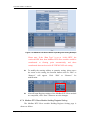
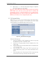
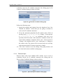
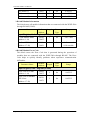
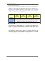
4.7.1 Modbus RTU Slave Module Coil Output Setting
The Modbus RTU Slave module Coil Output Setting page is shown as
follow:
Figure 4-22:Modbus RTU Slave Module Coil Output Setting Page
The detailed information of the parameters are as follow:
Please refer to section 4.7 for detailed information of the
“Address”, “Name”, “Polling Timeout” and “Timeout Retry
Interval” fields.
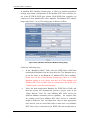
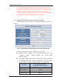
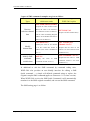
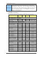
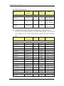
Data Model: WISE-580x offers 4 Data Model selections to match
the Modbus RTU Slave module configuration. The Data Model
list is as follow. In this case, please select ”Coil Output(0x)”.
Data Model
http://wise.icpdas.com
The Modbus Address of
Modbus RTU Slave Modules
Coil Output
0xxxx
Discrete Input
1xxxx
Input Register
3xxxx
Holding Register
4xxxx
43
ICP DAS WISE User Manual
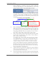
Start Address: Allows to set up the starting address of Coil Output
(0x) on the Modbus RTU Slave module you would like to
retrieve.
Continuous Data Number: After finishing the Start Address
setting, specify the Continuous Data Number, it is the number of
Coil Output data you would like to retrieve from the Start
Address.
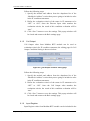
After finishing the “Start Address” and “Continuous Data
Number” setting, click on “Add” button. A new Coil Output
address block will be added to the Modbus address mapping table
(shown as below). All added address blocks will be located in
sequences staring from the Starting Address.
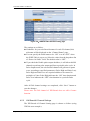
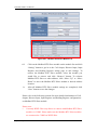
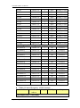
Please note: The address number on the first column “WISE-580x
Local Address” means the local Modbus address of WISE-580x to
keep the retrieved Coil Output data.
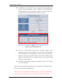
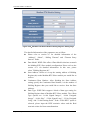
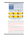
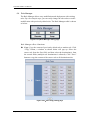
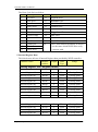
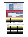
The following is an example about Coil Output setting for a
Modbus RTU Slave module. The starting Modbus address of the
Coil Output block is 00050(00000 + 50), it requires to set 4
continuous Coil Output data in the setting. So that the WISE-580x
can access the 00050, 00051, 00052 and 00053 Coil Output
address of the module, and these retrieved Coil Output data will
be kept in WISE-580x Modbus Address 00780, 00781, 00782 and
00783.
Figure 4-23:Modbus RTU Slave Module Coil Output Setting Example
http://wise.icpdas.com
44
ICP DAS WISE User Manual
To modify the starting address or quantity setting, please move
the cursor to the setting, the function buttons such as “Edit” or
“Remove” will appear. Click “Edit” or “Remove” for
modification.
After all Coil Output settings of the Modbus RTU Slave module
are completed, click “Save” button to save the changes.
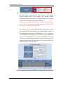
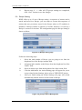
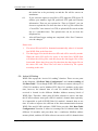
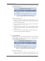
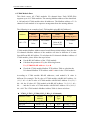
4.7.2 Modbus RTU Slave Module Discrete Input Setting
The Modbus RTU Slave module Discrete Input Setting page is shown
as follow:
Figure 4-24:Modbus RTU Slave Module Discrete Input Setting Page
The detailed information of the parameters are as follow:
Please refer to section 4.7 for detailed information of the
“Address”, “Name”, “Polling Timeout” and “Timeout Retry
Interval” fields.
Data Model: WISE-580x offers 4 Data Model selections to match
the Modbus RTU Slave module configuration. Please refer to the
section 4.7.1 for detailed information. In this case, please
select ”Discrete Input(1x)”.
http://wise.icpdas.com
45
ICP DAS WISE User Manual
Start Address: Allows to set up the starting address of Discrete
Input(1x) on the Modbus RTU Slave module you would like to
retrieve.
Continuous Data Number: After finishing the Start Address
setting, specify the Continuous Data Number, it is the number of
Discrete Input data you would like to retrieve from the Start
Address.
After finishing the “Start Address” and “Continuous Data
Number” setting, click on “Add” button. A new Discrete Input
address block will be added to the Modbus address mapping table
(shown as below). All added address blocks will be located in
sequences staring from the Starting Address.
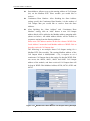
Please note: The address number on the first column “WISE-580x
Local Address” means the local Modbus address of WISE-580x to
keep the retrieved Discrete Input data.
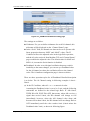
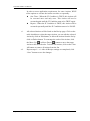
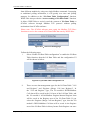
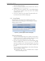
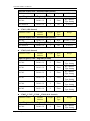
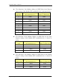
The following is an example about Discrete Input setting for a
Modbus RTU Slave module. The starting Modbus address of the
Discrete Input block is 10020(10000 + 20), it requires to set 6
continuous Discrete Input data in the setting. So that the
WISE-580x can access the 10020, 10021, 10022, 10023, 10024,
and 10025 Discrete Input address of the module, and these
retrieved Discrete Input data will be kept in WISE-580x Modbus
Address 10780, 10781, 10782, 10783, 10784 and 10785.
http://wise.icpdas.com
46
ICP DAS WISE User Manual
Figure 4-25:Modbus RTU Slave Module Discrete Input Setting Example
To modify the starting address or quantity setting, please move
the cursor to the setting, the function buttons such as “Edit” or
“Remove” will appear. Click “Edit” or “Remove” for
modification.
http://wise.icpdas.com
After all Discrete Input settings of the Modbus RTU Slave module
are completed, click “Save” button to save the changes.
47
ICP DAS WISE User Manual
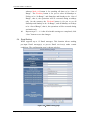
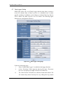
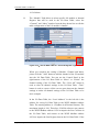
4.7.3 Modbus RTU Slave Module Input Register Setting
The Modbus RTU Slave module Input Register Setting page is shown
as follow:
Figure 4-26:Modbus RTU Slave Module Input Register Setting Page
The detailed information of the parameters are as follow:
Please refer to section 4.7 for detailed information of the
“Address”, “Name”, “Polling Timeout” and “Timeout Retry
Interval” fields.
Data Model: WISE-580x offers 4 Data Model selections to match
the Modbus RTU Slave module configuration. Please refer to the
section 4.7.1 for detailed information. In this case, please
select ”Input Register(3x)”.
Start Address: Allows to set up the starting address of Input
Register(3x) on the Modbus RTU Slave module you would like to
retrieve.
Continuous Data Number: After finishing the Start Address
setting, specify the Continuous Data Number, it is the number of
Input Register data you would like to retrieve from the Start
Address.
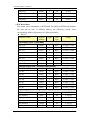
Data Type: WISE-580x support 6 kinds of data type setting for
Input Register of Modbus RTU Slave module. The 6 Data Type
options are “16-bit Signed Integer”, “16-bit Unsigned Integer”,
http://wise.icpdas.com
48
ICP DAS WISE User Manual
“16-bit Hex”, “32-bit Signed Long”, “32-bit Unsigned Long”, and
“32-bit Floating Point”. If the “16-bit HEX” option is selected,
please input the HEX max/min values and the Real max/min
values for linear transformation.
After finishing the “Start Address”, “Continuous Data Number”,
and “Data Type” setting, click on “Add” button. A new Input
Register address block will be added to the Modbus address
mapping table(shown as below). All added address blocks will be
located in sequences staring from the Starting Address.
Please note: The address number on the first column “WISE-580x
Local Address” means the local Modbus address of WISE-580x to
keep the retrieved Input Register data.
The following is an example about Input Register setting for a
Modbus RTU Slave module. The starting Modbus address of the
Input Register block is 30010(30000 + 10), it requires to set 3
continuous Input Register data in the setting, and the data type is
“32-bit Floating Point”. So that the WISE-580x can access the
30010, 30012, and 30014 Input Register address of the module,
and these retrieved Input Register data will be kept in WISE-580x
Modbus Address 30780, 30782, and 30784.
http://wise.icpdas.com
49
ICP DAS WISE User Manual
Figure 4-27:Modbus RTU Slave Module Input Register Setting Example
Please note: If the “Data Type” is set as “16-bit HEX”, the
retrieved HEX data from Modbus RTU Slave module would be
transformed to floating point automatically, and these
transformed data can be used in IF-THEN-ELSE rule setting.
To modify the starting address or quantity setting, please move
the cursor to the setting, the function buttons such as “Edit” or
“Remove” will appear. Click “Edit” or “Remove” for
modification.
After all Input Register settings of the Modbus RTU Slave module
are completed, click “Save” button to save the changes.
4.7.4 Modbus RTU Slave Module Holding Register Setting
The Modbus RTU Slave module Holding Register Setting page is
shown as follow:
http://wise.icpdas.com
50
ICP DAS WISE User Manual
Figure 4-28:Modbus RTU Slave Module Holding Register Setting Page
The detailed information of the parameters are as follow:
Please refer to section 4.7 for detailed information of the
“Address”, “Name”, “Polling Timeout” and “Timeout Retry
Interval” fields.
Data Model: WISE-580x offers 4 Data Model selections to match
the Modbus RTU Slave module configuration. Please refer to the
section 4.7.1 for detailed information. In this case, please
select ”Holding Register(4x)”.
Start Address: Allows to set up the starting address of Holding
Register(4x) on the Modbus RTU Slave module you would like to
retrieve.
Continuous Data Number: After finishing the Start Address
setting, specify the Continuous Data Number, it is the number of
Holding Register data you would like to retrieve from the Start
Address.
Data Type: WISE-580x support 6 kinds of data type setting for
Holding Register data of Modbus RTU Slave module. The 6 Data
Type options are “16-bit Signed Integer”, “16-bit Unsigned
Integer”, “16-bit Hex”, “32-bit Signed Long”, “32-bit Unsigned
Long”, and “32-bit Floating Point”. If the “16-bit HEX” option is
selected, please input the HEX max/min values and the Real
max/min values for linear transformation.
http://wise.icpdas.com
51
ICP DAS WISE User Manual
After finishing the “Start Address”, “Continuous Data Number”,
and “Data Type” setting, click on “Add” button. A new Holding
Register address block will be added to the Modbus address
mapping table(shown as below). All added blocks will be located
in sequences staring from the Starting Address.
Please note: The address number on the first column “WISE-580x
Local Address” means the local Modbus address of WISE-580x to
keep the retrieved Holding Register data.
The following is an example about Holding Input Register setting
for a Modbus RTU Slave module. The starting Modbus address of
the Holding Register block is 40060(40000 + 60), is requires to
set 2 continuous Holding Register data in the setting, and the data
type is “32-bit Floating Point”. So that the WISE-580x can access
the 40060 and 40062 Holding Register address of the module, and
these retrieved Holding Register data will be kept in WISE-580x
Modbus Address 40780 and 40782.
Figure 4-29:Modbus RTU Slave Module Holding Register Setting Example
http://wise.icpdas.com
52
ICP DAS WISE User Manual
Please note: If the “Data Type” is set as “16-bit HEX”, the
retrieved HEX data from Modbus RTU Slave module would be
transformed to floating point automatically, and these
transformed data can be used in IF-THEN-ELSE rule setting.
To modify the starting address or quantity setting, please move
the cursor to the setting, the function buttons such as “Edit” or
“Remove” will appear. Click “Edit” or “Remove” for
modification.
After all Holding Register settings of the Modbus RTU Slave
module are completed, click “Save” button to save the changes.
http://wise.icpdas.com
53
ICP DAS WISE User Manual
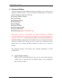
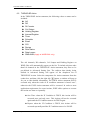
5 Advanced Setting
Advanced Setting provides additional features and allows you to perform more
setting on hardware devices. Click the Advanced Setting button, a column of
buttons will appear on the left of the page:
Internal Register Setting
Timer Setting
Schedule Setting
Email Setting
CGI Setting
Recipe Setting
Data Logger Setting
Active I/O Setting
SMS Setting (Apply to WISE-5801 only)
Please note: In order to avoid possible error when performing rule definition
(IF-THEN-ELSE), please always finish configuration in Advanced Setting before
starting to define Rules. Avoid unnecessary change in Advanced Setting after you
finish rule definition. Unexpected errors might occur if you violate this sequence:
Advanced Setting Rule Setting. In case you make any modification, please
double check your settings and Rules definition to make sure no errors are
present.
The following sections will describe more detailed information for these
configurations.
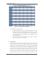
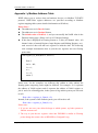
5.1 Internal Register Setting
WISE provides 48 Internal Registers; they can be used to hold temporary
variables and to read/write data via Modbus address. The configuration
page is shown as follow.
http://wise.icpdas.com
54
ICP DAS WISE User Manual
Figure 5-1:Internal Register setting page
The settings are as following steps:
i. A checkbox appears in front of each Internal Register; check the
checkbox to enable the Internal Register. Input a value if you want to
set a default value for the Internal Register, and set the nicknames for
the Internal Register, this nickname will be displayed on the
“Channel Status” page.
ii. After you finish all the Internal Registers selections and settings,
click “Save” button to save the settings.
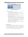
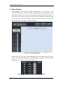
5.2 Timer Setting
WISE provides 12 groups Timer for timing functions. The Timer status can
be “Not Timeout” or “Timeout”. They can be included in the IF Condition
statements. The Timer Action can be “Start” or “Reset”. The Start Action
will start to run the Timer and if the Start Action is triggered one more time
when the Timer is running, the Timer will restart again. The Reset action
will reset the Timer and stop running the Timer. The Timer will be in
“Timeout” status only when the Timer is running and reached the setting
time, otherwise, the status of Timer will remain in “Not Timeout”. The
http://wise.icpdas.com
55
ICP DAS WISE User Manual
Timer setting interface is shown as below:
Figure 5-2:Timer setting page
Follow the following steps:
i. “Timer Amount” field is required. Select the total number of timer
you are going to use from the dropdown list.
ii. Specify the timer you want to set up by selecting its index number
iii.
iv.
v.
from the dropdown list of the “Index” field.
“Period” field is required for each timer; please input the period
interval in units of seconds.
Specify the initial status of each timer from the dropdown list of the
“Initial Status” field. Select “Start” indicates the timer will start to
count as soon as the hardware device is power up. “Stop” indicates
the Timer will remain off when the hardware device is power up; it
will not be activated until being triggered under certain conditions.
The default setting of initial Status is “Stop”.
Repeat steps ii ~ iv. After all timer settings are completed, click
“Save” button to save the changes.
5.3 Schedule Setting
WISE provides 12 groups of Schedules to setup prescheduled routine tasks.
The status of Schedule function can be “In Range” or “Out of Range”, they
can be included in the IF Condition statements. The Action of Schedule can
be “Enable” or “Disable”. Please note, if the Schedule is disabled, the status
will be “Out of Range”. Schedule setting page is shown as below:
http://wise.icpdas.com
56
ICP DAS WISE User Manual
Figure 5-3:Schedule setting page
Follow the following steps:
i.
Select the total number of schedule you are going to use from the
dropdown list of the “Schedule Amount” field.
ii.
iii.
iv.
Specify the schedule you want to set up by selecting its index
number from the dropdown list of the “Index” field.
Specify the initial status of each schedule from the dropdown list of
the “Initial Status” field. “Start” indicates the schedule will be
activated as soon as the hardware device is power up. “Stop”
indicates the schedule will remain inactive when the hardware
device is power up, it will not be activated until being triggered
under certain conditions.
Set up the Year and Month for this Schedule execution duration.
After you specify the Year and Month in the Date section, the
calendars corresponding to the Year and Month you specified will
appear as shown below:
http://wise.icpdas.com
57
ICP DAS WISE User Manual
Figure 5-4:Schedule Calendar setting page
v.
vi.
In the Time field, input the schedule “In Range” time. You can input
up to 12 time zones in a specific date. Select the start time and the
end time from the dropdown list. Click “Add” button to add a new
time zone. Please note: the time zones you specified can’t be
overlapped. If you specify an end time that is earlier than the start
time, such as 20:00:00 ~ 06:00:00, it indicates the end time will be
set one day after the start date.
On the calendars, click to toggle highlight on the dates you’d like to
execute or not execute the operations for this Schedule. If the date
shows a yellow background, it indicates the date is “In Range”, that
is, that date falls into the range that will execute the operations. On
the contrary, if the date shows a red background, it indicates that date
is “Out of Range”, that is, that date falls out of the range and will not
execute the operations. By default, all dates will be “In Range”, that
is, during the date range you select, the operation will be executed
every day. Clear All button is used to reset all dates to be “In Range”;
http://wise.icpdas.com
58
ICP DAS WISE User Manual
vii.
whereas Mark All button is for marking all dates to be “Out of
Range”. The Weekday button is for you to select all Mondays to
Fridays to be “In Range”, and Saturdays and Sundays to be “Out of
Range”, that is, the operations will be executed during weekdays
only. On the contrary, the Weekend button is for you to set all
Saturdays and Sundays to be “In Range”, and all Mondays to Fridays
to be “Out of Range”, that is, the operations will be executed during
weekends only.
Repeat steps ii ~ vi. After all schedule settings are completed, click
“Save” button to save the changes.
5.4 Email Setting
WISE supports up to 12 Email messages. This function allows sending
pre-input Email message(s) to pre-set Email receiver(s) under certain
conditions. The configuration page is shown as below:
Figure 5-5:Email setting page
http://wise.icpdas.com
59
ICP DAS WISE User Manual
Follow the following steps:
i. Specify the numbers of email messages you want to set up from the
dropdown list of the “E-mail Amount” field.
ii. Specify the email group number from the dropdown list of the
“Index” field.
iii. Enter the IP or the domain name of the SMTP server in the “SMTP
Server” field.
iv. If SMTP server requires account and password validation, please
v.
select the Authentication Checkbox, and continue steps v~vi to login
into the SMTP server. If SMTP server don’t need account and
password validation, uncheck the Authentication Checkbox and skip
steps v~vi, go directly to step vii.
Enter the SMTP server login ID in the “Login ID” field.
vi.
vii.
viii.
ix.
Enter the SMTP server password in the “Password” field.
Enter the sender’s name in the “Sender Name” field.
Enter the sender’s email address in the “Sender Email Address” field.
Enter the receiver’s email address in the “1st ~5th Receiver Email
x.
xi.
address” field. Please note: you can input up to 5 receivers, at least
one email address has to be entered. Please enter the email address in
sequence to avoid possible error.
Enter the email subject in the “Subject” field.
Enter the content in the “Content” field. The length of the content
cannot exceed 160 characters. In addition, Email provides an
encoded string for you to add current channel value into Email
content. You can use the I/O channel selection interface (shown as
below) to add channel value encoded string into the Email content.
Figure 5-6:Email encoded string setting
http://wise.icpdas.com
60
ICP DAS WISE User Manual
xii.
Repeat steps ii ~ xi. After all email groups settings are completed,
click “Save” button to save the changes.
Please note: WISE-580x Email sending function can only work with the
SMTP Email server that uses port 25 and must be without SSL
cryptographic protocols. A self-hosted SMTP server is recommended for
Email sending function or use Yahoo account for free Email service (The
SMTP server for Yahoo service is smtp.mail.yahoo.com.)
5.5 CGI Command Setting
WISE offers up to 12 sets of CGI Command setting. This function allows
sending pre-input CGI Command to pre-set Remote Server device under
certain conditions. The configuration page is shown as below:
Figure 5-7:CGI Command setting page
Follow the following steps:
i.
ii.
iii.
iv.
v.
Specify the numbers of CGI Commands you want to set up from
the dropdown list of the “CGI Amount” field.
Specify the CGI group number from the dropdown list of the
“Index” field.
Enter the Remote Server IP, Port number and CGI Command in the
“CGI Command” field.
Enter the number in the “Retry Count” field. It means the retry
number WISE will try when it can’t connect with Remote Server
device.
Enter the number in the “Retry Interval” field. It means the time
interval between each retry connection. The unit is Second.
http://wise.icpdas.com
61
ICP DAS WISE User Manual
vi.
Repeat steps ii ~ v. After all CGI groups settings are completed,
click “Save” button to save the changes.
5.6 Recipe Setting
WISE offers up to 12 sets of Recipe setting. A sequence of actions can be
stored and saved in a Recipe, you can setup to execute this sequence of
actions that was previously stored in the Recipe when an IF condition is
matched. A Recipe contains a sequence of actions, therefore, we can say a
Recipe is a macro for Actions. The configuration page for Recipe Setting is
shown as below:
Figure 5-8:Recipe setting page
Follow the following steps:
i.
Select the total number of Recipe you are going to use from the
dropdown list of the Recipe Amount field.
ii.
Assign an index number to the Recipe from the dropdown list of the
“Index” field.
iii.
Select an Action type from the dropdown list of the Action field.
iv.
Click the Add button. An Action Setting page will appear for you to
v.
set up related Action Settings, please refer to THEN/ELSE Action.
After you finish setting up Action Settings, the page will refresh
automatically and the Actions will be listed on Recipe.
Figure 5-9:Recipe Action Management
http://wise.icpdas.com
62
ICP DAS WISE User Manual
In order to meet application requirement, for some Actions, WISE
offers options to execute the Action one-time or repeatedly.
One Time:When the IF Condition is TRUE, this Action will
be executed once and only once. This Action will not be
executed again until the IF Condition turns to be TRUE again.
Repeat:When the IF Condition is TRUE, this Action will be
executed repeatedly until the IF Condition turns to be FALSE.
vi.
All selected Actions will be listed on the Recipe page. Click on the
radio checkbox to select the target Action, you can edit the selected
Action by click on Edit button, or delete the Action from the list by
click on Delete button. To rearrange the order of the Action, click
the Move Up
or Move Down
button to move the target
Action to the desired order. To delete all Actions, click on the Clear
vii.
All button to remove all actions from the list.
Repeat steps ii ~ vi. After all Recipe settings are completed, click
“Save” button to save the changes.
http://wise.icpdas.com
63
ICP DAS WISE User Manual
5.7 Data Logger Setting
WISE-580x offers one set of Data Logger function that allows system to
record I/O channel data in Data Log file at a scheduled time or under
specific condition. In addition, it also allows to send the Data Log files by
FTP or Email. The Data Log file is in CSV format. The following figure
illustrates the configuration interface:
Figure 5-10:Data Logger setting page
Follow the following steps:
i.
Select “Enable Data Logger” to enable the data logger function.
ii.
In the “File Name” field, input the data log file name. This name
has to be in English; the length is limited to 8 characters.
iii.
The “Data Format” field allows to edit data format and content. The
I/O channel drop down lists help for easy editing data log content
http://wise.icpdas.com
64
ICP DAS WISE User Manual
format. Following is examples for data log content coding; the
following coding indicates: I-7000 module(Address:1) AI4, I-7000
module (Address:4) DI5, I-7000 module(Address:2) DO4.
In the data log file, current date, time and data log type (Period
recording or Event trigger recording) will also be automatically
pasted to each data log item. The final data log content format will
be like this:
20110501,12:35:00,XXXX,…,…,…,P
Date and time of
User-input data
Specify the data log is
the Data Log item
log content
Period recording (P) or
string
Event trigger recording (E)
iv.
Select “Sampling Period” to enable period recording function in
v.
WISE. When the time reaches the period time interval, the data will
be recorded once in pre-set data format. The data recording will
keep going periodically. There are ten options: 10 secs, 30 secs, 1
min, 2 mins, 3 mins, 5 mins, 10 min, 20 min, 30 min, 1 hour.
In the “Close Log File” field, select the time interval to close a data
log file. There are eight options: 1 hour, 2 hours, 3 hours, 4 hours, 6
hours, 8 hours, 12 hours, 24 hours.
For example, if the “Close Log File” time interval is set as 3 hours,
and “Sampling Period” is set as 5 mins, it means WISE-580x will
vi.
vii.
record data every 5 mins. And the log file is created at 0 o’clock, 3
o’clock, 6 o’clock, 9 o’clock, 12 o’clock, 15 o’clock, 18 o’clock,
and 21 o’clock. When the system time reached these specified time,
the Data Log file will be closed automatically (the time interval of
this first file will be shorter than 3 hours) and create a new data log
file to record another 3 hours and so on.
Click the check box to specify the Log file to be sent by Email or
FTP. You can select both ways to send the Log file. If no option is
selected, the data file will not be sent.
If you select the option to send file by Email, select the Email index
you are going to send to when the data file is closed. The Email of
http://wise.icpdas.com
65
ICP DAS WISE User Manual
viii.
ix.
this index has to be previously set and the file will be sent as an
attachment.
If you select the option to send file by FTP, input the FTP Server IP
address, port number, login ID, password, FTP path and Timeout
information. There are two options for “Time to Upload”, you can
choose to upload the file when the time of the Log file reached the
“Closed File” time interval via FTP, or upload all files saved at that
day at a scheduled time. The upload time can be set from the
dropdown list.
After all Data Logger settings are completed, click “Save” button to
save the changes.
Please note:
1. The micro SD card will be formatted automatically when it is inserted
2.
into WISE-580x at the first time.
The data logger files inside the micro SD card will be stored by month.
When the micro SD card’s free space is less than 20%, WISE-580x
will delete the old log files, and only keeps the data logger files of the
last month. Please don’t keep any file other than the data logger files in
the micro SD card. These files will also be deleted by the system
according to this rule.
5.8 Active I/O Setting
WISE-580x equips the “Active I/O sending” function. There are two parts
in this function: “I/O Data Table Configuration” and “Active sending of
I/O Data Table”. Even though WISE-580x allows to connect with up to 16
I-7000 I/O modules, and 4 Modbus RTU Slave I/O modules at the same
time, however, the channel data of each I/O module that WISE-580x
received is located in the different Modbus Address memory block of
WISE-580x. Therefore, when using SCADA software to retrieve the data,
the SCADA software must poll each I/O module’s channel data separately.
It is impossible to poll all WISE-580x I/O module’s channels data at one
time. In order to improve the efficient of the data communication between
WISE-580x and SCADA software, WISE-580x provides “I/O Data Table
Configuration” function. It allows to rearrange the I/O channels data from
different I/O modules and puts them into a continuous Modbus address
memory block, and then SCADA software can retrieve all I/O channels data
http://wise.icpdas.com
66
ICP DAS WISE User Manual
from different modules by using one single Modbus command. Comparing
to traditional polling mechanism, it will greatly save time and polling
attempts. In addition to the “I/O Data Table Configuration” function,
WISE-580x also provide the “Active sending of I/O Data Table” function.
It allows WISE-580x to actively send the content of I/O Data Table to
SCADA software through Modbus TCP protocol without polling
mechanism from SCADA software.
Please note: The SCADA software must equip the Modbus TCP Slave
function to receive the content of I/O Data Table that sent by WISE-580x.
Figure 5-11:Active I/O Setting page
Follow the following steps:
i.
Select “Enable I/O Data Table configuration” to enable the I/O Data
Table function, then the I/O Data Table and the configuration UI
will be shown as follow:
Figure 5-12:I/O Data Table configuration UI
ii.
There are two data arrangement types for the I/O Data Table: ”Coil
and Register” and “Register (Merge Coil into Register)”. In
the ”Coil and Register” type, The I/O module’s DI/DO/Modbus
Coil data will be saved in the Coil area of the I/O Data Table, and
the I/O module’s AI/AO/Modbus Register/Internal Register data
will be saved in the Register area of the I/O Data Table. If you
select the “Register (Merge Coil into Register)” type, then the I/O
module’s DI/DO/Modbus Coil data will be saved in the Register
area of the I/O Data Table in binary format. Each Register can store
http://wise.icpdas.com
67
ICP DAS WISE User Manual
16 Coils data.
iii.
The “Module” field allows to select specific I/O module or Internal
Register that will be used in the I/O Data Table; select the
“Channel” and “Index” number from the drop down lists to edit the
table configuration of the I/O module’s channel.
Figure 5-13:The I/O Data Table for ”Coil and Register” type
When you complete the setting of Module, Channel and Index,
please click the “Add” button to add the channel of the I/O module
into the I/O Data Table. You can use the Control Panel in the
right-bottom of the I/O Data Table to “Move” or “Delete” the
channel setting of the I/O Data Table. The “Clear All” button is
used to clear all channel settings in the I/O Data Table. “Trim”
button is used to remove all the excess space between the channel
settings to make all channel settings of the I/O Data Table to be
more compact.
In the I/O Data Table, the “Local Address” in the left side is the
address for saving I/O Data Table in the WISE Modbus Address
Table. The starting address is 1230(Base 0 & Decimal format). The
maximum length is 300. Therefore, SCADA software can connect
to the WISE Modbus address 01230 to inquire the first Coil data in
the I/O Data Table, and connect to the WISE Modbus address
41230 to inquire the first Register data in the I/O Data Table. If the
http://wise.icpdas.com
68
ICP DAS WISE User Manual
“Active sending of I/O Data Table” function is enabled, the
“Receiver Start Address” in the upper area of the I/O Data Table is
the address of the Receiver’s(SCADA software) Modbus starting
address. The content of the I/O Data Table that WISE-580x send
actively to Receiver’s(SCADA software with Modbus TCP Slave
function) will be saved from the starting address. The naming rule
of the channel inside the I/O Data Table is: (RS-485 Address)
Channel Type + Channel Index. For example, (1)DI0 is for the DI0
channel of the I/O module with RS-485 address 1
The following figure shows an example of the data arrangement of
the I/O Data Table for the “Register (Merge Coil into Register)”
type.
Figure 5-14:The I/O Data Table for ”Register(Merge Coil into Register)” type
iv.
Enable the “Active sending of I/O Data Table”, then WISE-580x
will actively send all the I/O Data Table‘s channels data to the
SCADA software.
http://wise.icpdas.com
69
ICP DAS WISE User Manual
.
Figure 5-15:Attribute of “Active I/O Data Sending”
It is required to set the Receiver’s (SCADA software) IP address,
the Modbus TCP Slave’s Port number and NetID of the Receiver’s,
the Timeout value, and the type of “Timing to send out I/O Data”.
There are two options for the “Timing to send out I/O Data”, one
option is to send out the data when an I/O channel value change
takes place, the other is to send out the data at periodic time
schedule.
5.9 SMS Setting
WISE-5801 offers SMS alarm message sending and SMS command
receiving functions. For SMS alarm message sending function; WISE-5801
offers up to 12 SMS alarm settings. It allows to send pre-set SMS alarm to
specific phone numbers. For SMS command receiving function;
WISE-5801 allows to set up maximum 3 authorized phone numbers to
receive SMS commands. WISE-5801 will execute the commands received
from authorized phone numbers only. There are three types of SMS
commands:
Retrieve real-time channel data: you can retrieve specific channel
real-time data, one SMS command message can require up to 10
channel data values. To retrieve the channel data of WISE-5801, follow
http://wise.icpdas.com
70
ICP DAS WISE User Manual
the following coding rules to send a SMS command to WISE-5801:
Initiate each data string with a “$”; the symbol “$”
indicates the string following after is real-time data.
$ABaiC
A indicates the module type, B
indicates module location. A can
be set as x, m, n. For XW-board,
put “x” in A, skip B. For I-7000
modules, put “m” in A, put its
Real-Time Data Code:
location address in B(1~16). For
Modbus RTU device, put “n” in
A, and put its location address in
B(17~20). For Internal Register,
skipped both A and B.
ai
AI Channel Data
ao
AO Channel Data
di
DI Channel Data
do
DO Channel Data
ci
DI Counter or RTU
Discrete Input Data
co
RTU Coil Output
Data
ri
RTU Input Register
Data
C indicates the index number of
the channel, don’t input a
non-existing index number.
ro
RTU Holding
Register Data
ir
Internal Register
Data
Figure 5-16:SMS Command Data Retrieve Coding Rules
Modify channel data: WISE-5801 allows to modify output channel
and Internal Register data by SMS command. Each SMS command
message allows to modify one output channel or Internal Register
value. Specify the output channel or Internal Register by the coding
rules as described above, add a “/” at the end of the string and then add
the data value you would like to change to (For DO: input 0 or 1, 0
indicates OFF and 1 indicates ON. For AO: input the value in floating
point format.)
Modify SMS command variable data: WISE-5801 offers up to 12
SMS command variables. The status of the variables can be set as 0 or
1. The status of SMS command variable can be included in IF
Condition as part of logic rules. You can send a SMS command
message to modify the status of the variable, and then perform the
execution of an Action that has been previously set.
http://wise.icpdas.com
71
ICP DAS WISE User Manual
3 types of SMS command examples are given as follow:
SMS Command
Types
The SMS Command
which user sends
The SMS message which
WISE-5801 replies
GET:$xdi0,$m1ai2,$n18ro3
(Inquires the value of DI0 on XW-
Retrieve
real-time channel
Board, the value of AI channel 2
data
and the value of Holding Register
on I-7000 that locates at address 1
GET ON,8.7,4.3
(Replies real-time channel data)
address 18 on Modbus RTU device
that locates at address 3.)
SET:$m2ao1/2.5
Modify
channel data
SET I-7024(2) AO
(Modify the value on AO channel Channel 1 as 2.5
1 on the I-7024 that locates at
(Replies that the value on AO
address 2; the value is modified to
channel 1 on the I-7024 has been
be 2.5.)
modified to 2.5)
Modify SMS
ACT:2/1
command
variable data
(Modify
SMS Command 2 set as 1
(Replies that the value of
the
value
of
SMS
SMS
command variable 2 has been
Command variable 2 to be 1.)
modified to 1 )
In additional to edit the SMS command by command coding rules,
WISE-5801 also provides an user-friendly interface for editing a SMS
Quick command – a simple self-defined command string to replace the
original complex SMS command(applies to Firmware v2.3 or later version).
When WISE-5801 receives the SMS Quick Command, it will automatically
translate it to the SMS original command, and execute the SMS command.
The SMS setting page is as follow:
http://wise.icpdas.com
72
ICP DAS WISE User Manual
Figure 5-17:SMS Setting Page
Please follow the steps below:
i.
In the PIN field, input the 4 digit SIM card PIN code. If the PIN
code is not required, leave the field blank.
ii.
Enable the ”Enable WISE to accept SMS Command” function to
start the SMS command receiving function. In the “Authorized
Phone Number” field, input the phone numbers you would like to
authorize to send SMS commands to WISE-5801. Please note: the
Authorized Phone Number has to be input in the format: Country
code, area code and number. For example, if the Authorized Phone
Number is a cell phone number 0987654321 in Taiwan area, please
input the Authorized Phone Number as “886987654321”.
http://wise.icpdas.com
73
ICP DAS WISE User Manual
iii.
To use the SMS Quick command edition function, please click the
“Setting” button in the Quick Command field, then a “SMS Quick
Command Setting” Page will pop up as follow:
Figure 5-18:SMS Quick Command Setting Page
Input a simple, self-defined command string in the “Quick
Command” field, and then edit the original SMS command by
selecting the command type and I/O channel from the dropdown list
(shown as figure above) in the “Original Command” field . Press
“Add” button after finishing the SMS command setting; the SMS
Quick command and its corresponding SMS Original Command
will be shown in the Quick Command List field. Now you can send
the SMS Quick command string “DATA” (shown as the Quick
Command List in the figure above) to WISE-5801, after
WISE-5801 receiving the “DATA” command, it will execute its
original command “GET:$m1di0,$m1di1,$m1di2,$m2ai0,$m3ao0,
$ir1,’ to retrieve the DI0/DI1/DI2 channel values of I/O module
(Address=1), the AI0 channel value of I/O module(Address=2), the
AO0 channel value of I/O module(Address=3) and the IR0(Internal
Register 0) value, and then will send back all the values to you.
For “SET” and “ACT” SMS Command, there are two options for
SMS Quick Command edition. The first option is as the second
listed Quick Command on the Quick Command List (shown as
figure above). The “AO” quick command replaces the original
command ”SET:$m3ao0/2.3”, when WISE-5801 receive the SMS
http://wise.icpdas.com
74
ICP DAS WISE User Manual
Quick command “AO”, it will set the AO channel 0 of the I/O
module(Address= 3) to be 2.3. The second option is to edit the SMS
Quick command “AO” to be ”SET:$m3ao0” as the SMS Original
command string. In this format, when use the “AO” Quick
command, it is required to append a value to the Quick command
string, such as: “AO/2.3”. WISE-5801 will set the AO channel 0 of
the I/O module(Address=3) to be 2.3. In this way, the output
channel value can be modified flexibly as any other values by
sending command like: ”AO/5.6”, ”AO/7.8”.
iv.
v.
vi.
vii.
viii.
In the “SMS Amount” field, specify the total number of SMS alarm
messages you are going to use from the dropdown list.
In the “Index” field, specify the SMS index number to be set up
from the dropdown list.
In the “Phone Number” field, input the phone numbers to receive
the SMS alarm messages. The SMS can be sent to multiple
receivers. Separate the phone number by “,”.
Enter the content in the “Message” field. If the Unicode mode is
adopted, the length of the content cannot exceed 70 characters. If
the Unicode mode is not selected (support English characters), the
length of the content limit is 160 characters. To quickly add a
real-time I/O channel value into the SMS content, use the I/O
channel selection interface (shown as figure above) to add the I/O
channel value encoded string into the SMS content.
Repeat steps iv~ vi. After all SMS alarm settings are completed,
click “Save” button to save the changes.
http://wise.icpdas.com
75
ICP DAS WISE User Manual
6 Rules Setting
After finishing all Advanced Setting configurations, you can start to edit
IF-THEN-ELSE rules. Click the “Rules Setting” button, a Rule Manager table
will appear, and the list of rules will be displayed on the left side of the page. At
the left side of the page, the status of each rule will be displayed. And at the right
side of the page will show detailed content of each rule that was previously
defined. The rule setting page is shown as below:
Figure 6-1:Rules setting page
On the left side of the page, a Rule Manager table will appear at the top of the
page. (More detailed information for Rule Manager will follow.) Under the Rule
Manager table, the list of rule contains four items:
Figure 6-2:Enable rules, edit rules and status display
http://wise.icpdas.com
76
ICP DAS WISE User Manual
Enable: A checkbox appears before each rule; check the checkbox to
enable the rule and this rule will be executed after being downloaded,
otherwise it will only be stored temporarily.
No.: Indicates the identification number of the rule. To avoid possible error,
it is recommended to assign the identification number in sequence.
Edit: Click the Edit button to edit detail logic content of the rule.
Status: “OK” indicates this rule is successfully defined. “Error” indicates
there is error occurs. Please note: if you make modification in IO setting
(I-7000 Module, XW-Board or Modbus RTU Slave module) or in
Advanced Setting after finish defining the rules, it might cause unexpected
error due to the changes, some variables may no longer exist. Therefore, in
case you make any modification, please double check your settings and
Rules definition to make sure no errors are present.
Click the “Edit” button, the Rules Setting page will appear:
Figure 6-3:Rule setting page
The rule number will be displayed at the top of the page. The Description field
provides a space for you to make a brief description of this Rule. An
IF-THEN-ELSE Rule setting table appears under the description section. Each
Rule offer 3 IF conditions. You could create IF(condition) statements by selecting
appropriate operator (AND, OR) from the dropdown list. In order to avoid
possible errors, the design of this table is foolproof: You are required to finish
setting up Condition1 before moving on Condition2, and so on. Each Rule also
offers 3 THEN actions, and 3 ELSE actions. More detailed information will
follow.
http://wise.icpdas.com
77
ICP DAS WISE User Manual
6.1 IF Condition
In IF Condition statement, the following values or their status can be
included as evaluation criteria:
AI
DI
DI Counter
Discrete Input
Coil Output
Input Register
Holding Register
Internal Register
Timer
Schedule
Rule Status
SMS Command (Apply to WISE-5801 only)
The AI channels, DI channels, Discrete Input, Coil Output, Input Register
and Holding Register on WISE-580x will automatically appear on the list.
To include subjects other than I/O channels in the IF Condition statement;
they have to be pre-defined in Advanced Setting first. The subjects that
already being defined in Advanced Setting will appear on the dropdown list
of IF Condition. Select the subject you want to use, and then click right side
button, a window will pop up for you to edit detailed information.
6.1.1
AI
AI channel value from XW-Board or I-7000 module can be included in
the IF condition statements; the editing page for AI Condition Setting is
shown as below:
Figure 6-4:AI condition setting page
Follow the following steps:
http://wise.icpdas.com
78
ICP DAS WISE User Manual
i. Specify the module and channel from the dropdown list of the
“Module & Channel” section that you are going to include its
value in the IF condition statements.
The “Module & Channel” section of XW-Board is shown as below
(use XW304 AI channel 0 as an example):
The “Module & Channel” section of I-7000 is shown as below; use
I-7005 (Address 1) AI channel 0 as an example:
The “Module & Channel” section of DL-100T485 is shown as
below; select a channel from “Humidity”, “Temperature(°C)” and
“Temperature(°F)”:
ii. Set up the expression statement for this channel value. Select an
operator from “=”,”>”,”<”,”>=” or “<=”.
iii. And then specify the evaluation value. If this AI channel value
match the evaluation criteria, the result of this condition evaluation
will be “true”.
You can compare the AI channel value with the following 3 values
for condition evaluation:
Self-Defined value:Giving a self-defined value to compare with
the AI channel value.
Channel value : Using AI channel values from other
modules(XW-Board or I-7000) to compare with the AI channel
value.
http://wise.icpdas.com
79
ICP DAS WISE User Manual
Internal Register:Using the internal register value to compare
with the AI channel value.
iv. Click “Save” button to save the settings. The popup window will
be closed and return to the Rule settings page.
6.1.2
DI
DI channel value from XW-Board or I-7000 module can be used as
evaluation criteria for IF condition statement; the editing page for DI
Condition Setting is shown as below:
Figure 6-5:DI condition setting page
Follow the following steps:
i. Specify the module and channel from the dropdown list of the
“Module & Channel” section that you are going to include its
value in the IF condition statements.
ii. Define the evaluation criteria of the status in IF statement to be
“OFF”, “ON”, “ON to OFF”, “OFF to ON” or “Change”. Once the
DI channel value matches the evaluation criteria, the result of this
condition evaluation will be “true”. Please note: If the statement
involves state transitions: “ON to OFF”, “OFF to ON” and
“Change”, the action will be executed only once and only at the
moment when the state transition occurs.
iii. Click “Save” button to save the settings. This popup window will
be closed and return to the Rule settings page.
6.1.3
DI Counter
DI counter value from XW-Board or I-7000 module can be used as
http://wise.icpdas.com
80
ICP DAS WISE User Manual
evaluation criteria for IF condition statement; the editing page for DI
Counter Condition Setting is shown as follow:
Figure 6-6:DI Counter condition setting page
Follow the following steps:
i. Specify the module and channel from the dropdown list of the
“Module & Channel” section that you are going to include its
value in the IF condition statements.
ii. Set up the expression statement for this counter value. Select an
operator from “=”,”>”,”<”,”>=”,“<=” or “Change”. If the operator
is “=”,”>”,”<”,”>=” or “<=”, an evaluation value has to be
specified; if the DI counter value match the evaluation criteria, the
result of this condition evaluation will be “true”. If the operator is
“Change”, the condition will be “true” when there is a change to
the counter value. The action will be executed only once and only
at the moment when DI Counter experience a change.
iii. Click “Save” button to save the settings. This popup window will
be closed and return to the Rule settings page.
6.1.4
Discrete Input
Discrete Input value from Modbus RTU module can be used as
evaluation criteria for IF condition statement; the editing page for
Discrete Input Condition Setting is shown as below:
Figure 6-7:Discrete Input condition setting page
http://wise.icpdas.com
81
ICP DAS WISE User Manual
Follow the following steps:
i. Specify the module and address from the dropdown list of the
“Module & Address” section that you are going to include its value
in the IF condition statements.
ii. Define the evaluation criteria of the status in IF statement to be
“OFF” or “ON”. Once the Discrete Input value matches the
evaluation criteria, the result of this condition evaluation will be
“true”.
iii. Click “Save” button to save the settings. This popup window will
be closed and return to the Rule settings page.
6.1.5
Coil Output
Coil Output value from Modbus RTU module can be used as
evaluation criteria for IF condition statement; the editing page for Coil
Output Condition Setting is shown as below:
Figure 6-8:Coil Output condition setting page
Follow the following steps:
i. Specify the module and address from the dropdown list of the
“Module & Address” section that you are going to include its value
in the IF condition statements.
ii. Define the evaluation criteria of the status in IF statement to be
“OFF” or “ON”. Once the Coil Output value matches the
evaluation criteria, the result of this condition evaluation will be
“true”.
iii. Click “Save” button to save the settings. This popup window will
be closed and return to the Rule settings page.
6.1.6
Input Register
Input Register value from Modbus RTU module can be included in the
http://wise.icpdas.com
82
ICP DAS WISE User Manual
IF condition statements; the editing page for Input Register Condition
Setting is shown as below:
Figure 6-9:Input Register condition setting page
Follow the following steps:
i. Specify the module and address from the dropdown list of the
“Module & Address” section that you are going to include its value
in the IF condition statements.
ii. Set up the expression statement for this channel value. Select an
operator from “=”,”>”,”<”,”>=” or “<=”.
iii. And then specify the evaluation value. If this Input Register value
match the evaluation criteria, the result of this condition evaluation
will be “true”.
iv. Click “Save” button to save the settings. The popup window will
be closed and return to the Rule settings page.
6.1.7
Holding Register
Holding Register value from Modbus RTU module can be included in
the IF condition statements; the editing page for Holding Register
Condition Setting is shown as below:
Figure 6-10:Holding Register condition setting page
Follow the following steps:
i. Specify the module and address from the dropdown list of the
“Module & Address” section that you are going to include its value
http://wise.icpdas.com
83
ICP DAS WISE User Manual
in the IF condition statements.
ii. Set up the expression statement for this channel value. Select an
operator from “=”,”>”,”<”,”>=” or “<=”.
iii. And then specify the evaluation value. If this Holding Register
value match the evaluation criteria, the result of this condition
evaluation will be “true”.
iv. Click “Save” button to save the settings. The popup window will
be closed and return to the Rule settings page.
6.1.8
Internal Register
Internal Register value can be used as evaluation criteria for IF
condition statement; the editing page for Internal Register Condition
Setting is shown as follow:
Figure 6-11:Internal register condition setting page
Follow the following steps:
i. Select the Internal Register that you are going to use the value as
evaluation criteria for IF condition statement. Specify the Internal
Register Index from the dropdown list of “Index” field.
ii. Set up the expression statement for this Internal Register value.
Select an operator from “=”,”>”,”<”,”>=” or “<=”, and then
specify the evaluation value. If this Internal Register value match
the evaluation criteria, the result of this condition evaluation will
be “true”.
You can compare the Internal Register value with the following 3
values for condition evaluation:
Self-Defined value:Giving a self-defined value to compare
with the Internal Register value
http://wise.icpdas.com
84
ICP DAS WISE User Manual
Channel value:Using AI channel values from other modules
(XW-Board or I-7000) to compare with the Internal Register
value.
Internal Register:Using another number of internal register
value to compare with the Internal Register value.
iii. Click “Save” button to save the settings. The popup window will
be closed and return to the Rule settings page.
6.1.9
Timer
Timer condition can be used as evaluation criteria for IF condition
statement; the editing page for timer condition setting is shown as
follow:
Figure 6-12:Timer condition setting page
Follow the following steps:
i. Select the timer that you are going to use its status as evaluation
criteria for IF condition statement. Specify the timer index from
the dropdown list of the “Index” field.
ii. Define the evaluation criteria of the timer status in IF statement to
be “Not timeout” or “Timeout”. If the timer status match the
evaluation criteria, the result of this condition evaluation will be
http://wise.icpdas.com
85
ICP DAS WISE User Manual
“true”.
iii. Click “Save” button to save the settings. The popup window will
be closed and return to the Rule settings page.
6.1.10 Schedule
Schedule condition can be used as evaluation criteria for IF condition
statement; the editing page for Schedule condition Setting is shown as
follow:
Figure 6-13:Schedule condition setting page
Follow the following steps:
i. Select the schedule that you are going to use its status as
evaluation criteria for IF condition statement. Specify the schedule
index from the dropdown list of the “Index” field.
ii. Define the evaluation criteria of the status in IF statement to be
“Out of Range” or “In Range”. If the status of the schedule
matches the evaluation criteria, the result of this condition
evaluation will be “true”.
iii. Click “Save” button to save the settings. The popup window will
closed and return to the rule settings page.
6.1.11 Rule Status
The Rule Status (if the Rule is disabled or enabled) can be used as
evaluation criteria for IF condition statement. Please note: there must
be at least one edited rule on WISE controller for setting up Rule Status
in the IF Condition Setting page. The editing page for Rule Status
Condition Setting is shown as below:
http://wise.icpdas.com
86
ICP DAS WISE User Manual
Figure 6-14:Rule Status condition setting page
Follow the following steps:
i. Specify the index number of the Rule that is going to be used in
the IF Condition statement from the dropdown list of the “Index”
field.
ii. Specify the Rule status to be Disable or Enable from the dropdown
list of the “Status” field. When the Rule status matches the
specified status, the evaluation result will be “true”.
iii. Click “Save” button to save the settings. The Rule Status
Condition Setting page will be closed and return to the Rule setting
page.
6.1.12 SMS Command
The SMS Command variable status can included in IF Condition as
part of logic rules. It allows to modify the SMS Command variable
status for remote control. The setting page is shown as below:
Figure 6-15:SMS Command setting page
Please follow the steps below:
i. In the “Index” field, specify the SMS command variable index
number you want to use in IF condition from the dropdown list.
ii. In the “Value” field, set the SMS command variable status to be “0”
or “1”. Once when the variable matches this pre-set status value, the
evaluation result will be TRUE. The default pre-set status value is
http://wise.icpdas.com
87
ICP DAS WISE User Manual
“0”. Click “Save” button to save the settings. The popup window
will be closed and will return to the rule setting page.
http://wise.icpdas.com
88
ICP DAS WISE User Manual
6.2 THEN/ELSE Action
In the THEN/ELSE Action statement, the following values or status can be
included:
AO
DO
DI Counter
Coil Output
Holding Register
Internal Register
Timer
Schedule
Email
CGI
Recipe
Rule Status
Data Logger
SMS Alarm( Apply to WISE-5801 only)
The AO channels, DO channels, Coil Output and Holding Register on
WISE-580x will automatically appear on the list. To include subjects other
than I/O channels in the THEN/ELSE Action statement; they have to be
pre-defined in Advanced Setting first. The subjects that already being
defined in Advanced Setting will appear on the dropdown list of
THEN/ELSE Action. Select the component for Action statement from the
combo box, and then click the right side
button, a window will pop up
for you to edit detailed information. The THEN Action statement will be
executed only when the result of IF condition statement is found “true”;
otherwise the ELSE Action statement will be executed. In order to meet
application requirement, for some Actions, WISE offers options to execute
the Action one-time or repeatedly.
One Time: when the IF Condition is TRUE, this Action will be
executed once and only once. This Action will not be executed
again until the IF Condition turns to be TRUE again.
Repeat: when the IF Condition is TRUE, this Action will be
executed repeatedly until the IF Condition turns to be FALSE.
http://wise.icpdas.com
89
ICP DAS WISE User Manual
Figure 6-16:”One-Time Action” &”Repeat Action” Items
6.2.1
AO
You can execute an action in AO channel of XW-Board or I-7000
module in THEN/ELSE Action statement; the editing page for AO
Action is shown as follow:
Figure 6-17:AO action setting page
Follow the following steps:
i. From the dropdown list of the “Module & Channel” field, select
the AO channel index to execute actions.
ii. Specify the Operator in the “Operator” field. The 3 operators are as
follow:
“=”:Indicate assign the new AO channel value as the value in
“Value” field
“+=”:Indicate assign the new AO channel value as the
original AO channel value plus the value in “Value” field.
“-=”:Indicate assign the new AO channel value as the
original AO channel value minus the value in “Value” field.
iii. In the “Value” field, 4 sources can be used as channel value :
Self-Defined Value: assign a self-defined value
AI Channel value: using AI channel values from XW-Board or
I-7000
http://wise.icpdas.com
90
ICP DAS WISE User Manual
AO Channel value: using AO channel values from XW-Board
or I-7000
Internal Register: using value of Internal Register
iv. Click “Save” button to save the settings. The popup window will
be closed and will return to the rule setting page.
6.2.2
DO
You can execute an action in DO channel of XW-Board or I-7000
module in the THEN/ELSE Action statement; the editing page for DO
Action is shown as follow:
Figure 6-18:DO action setting page
Follow the following steps:
i. Select the DO channel from the dropdown list of channel field in
the “Module & Channel” section.
ii. Specify the output value of DO Channel from the dropdown list of
the “Channel Value” field. The output value can be “OFF”, “ON”
or “Pulse Output” (Pulse Output applies to XW-Board only). For
I-7088 belongs to PWM (Pulse width modulation) modules, the
DO channel Action will be “Start PWM” or “Stop PWM”.
iii. Click “Save” button to save the settings. The popup window will
http://wise.icpdas.com
91
ICP DAS WISE User Manual
be closed and return to the Rule settings page.
6.2.3
DI Counter
You can reset DI counter in the THEN/ELSE Action statement; the
editing page for DI counter Action is shown as follow:
Figure 6-19:DI Counter action setting page
Follow the following steps:
i. Select the DI channel to reset DI counter from the dropdown list of
channel field in the “Module & Channel” section.
ii. Click “Save” button to save the settings. The popup window will
be closed and return to the Rule settings page.
6.2.4
Coil Output
You can execute an action in Coil Output channel of Modbus RTU
module in the THEN/ELSE Action statement; the editing page for Coil
Output Action is shown as follow:
Figure 6-20:Coil Output action setting page
Follow the following steps:
i. Select the Coil Output from the dropdown list of channel field in
the “Module & Address” section.
ii. Specify the output value of Coil Output from the dropdown list of
the “Address Value” field. The output value can be “OFF” or,
“ON”.
http://wise.icpdas.com
92
ICP DAS WISE User Manual
iii. Click “Save” button to save the settings. The popup window will
be closed and return to the Rule settings page.
6.2.5
Holding Register
You can execute an action in Holding Register channel of Modbus
RTU module in THEN/ELSE Action statement; the editing page for
Holding Register Action is shown as follow:
Figure 6-21:Holding Register action setting page
Follow the following steps:
i. From the dropdown list of the “Module & Address” field, select
the Holding Register address index to execute actions.
ii. Specify the Operator in the “Operator” field. The 3 operators are as
follow:
“=”:Indicate assign the new Holding Register address value
as the value in “Value” field
“+=”:Indicate assign the new Holding Register address value
as the original Holding Register address value plus the value
in “Value” field.
“-=”:Indicate assign the new Holding Register address value
as the original Holding Register address value minus the value
in “Value” field.
iii. In the “Value” field, giving a self-defined value
iv. Click “Save” button to save the settings. The popup window will
be closed and will return to the rule setting page.
6.2.6
Internal Register
You can modify the value of Internal Register in the THEN/ELSE
Action statement; the editing page for Internal Register Action Setting
http://wise.icpdas.com
93
ICP DAS WISE User Manual
is shown as below:
Figure 6-22:Internal Register action setting page
Follow the following steps:
i. Select the pre-defined Internal Register from the dropdown list of
the “Index” field. Please note: the Internal Register you select has
to be enabled in Advanced Setting.
ii. Specify the Operator in the “Operator” field. The 3 operators are as
follow:
“=”:Indicate assign the new Internal Register value as the
value in “Value” field.
“+=”:Indicate assign the new Internal Register value as the
original Internal Register value plus the value in “Value” field.
“-=”:Indicate assign the new Internal Register value as the
original Internal Register value minus the value in “Value”
field.
iii. In the “Value” field, 4 sources can be used as value :
Self-Defined Value: assign a self-defined value
AI Channel value: using AI channel values from XW-Board or
I-7000
AO Channel value: using AO channel values from XW-Board
or I-7000
http://wise.icpdas.com
94
ICP DAS WISE User Manual
Internal Register: using value of Internal Register
iv. Click “Save” button to save the settings. The popup window will
be closed and return to the Rule settings page.
6.2.7
Timer
You can change the Timer status (to Start or to Reset the Timer) in the
THEN/ELSE Action statement; the editing page for Timer Action
Setting is shown as below:
Figure 6-23:Timer action setting page
Follow the following steps:
i. Select the pre-defined Timer from the dropdown list of the “Index”
field. Please note: the Timer you select has to be enabled in
Advanced Setting.
ii. Specify you want to “Reset” or “Start” this Timer when this
THEN/ELSE Action statement is executed.
iii. Click “Save” button to save the settings. The popup window will
be closed and return to the Rule settings page.
6.2.8
Schedule
You can change the Schedule status (to Enable or to Disable the
http://wise.icpdas.com
95
ICP DAS WISE User Manual
Schedule) in the THEN/ELSE Action statement; the editing page for
Schedule Action Setting is shown as below:
Figure 6-24:Schedule action setting page
Follow the following steps:
i. Select the pre-defined Schedule from the dropdown list of the
“Index” field. Please note: the Schedule you select has to be
enabled in Advanced Setting.
ii. Specify you want to “Enable” or “Disable” this schedule when this
THEN/ELSE Action statement is executed.
iii. Click “Save” button to save the settings. The popup window will
be closed and return to the Rule settings page.
6.2.9 Email
You can send a message to an Email group when executing a
THEN/ELSE Action statement; the editing page is as below:
Figure 6-25:Email action setting page
Follow the following steps:
http://wise.icpdas.com
96
ICP DAS WISE User Manual
i. Select the pre-set Email group from the dropdown list of the
“Index” field. Please note: the Email you select has to be enabled
in Advanced Setting. The Email group information will be
displayed for you to verify if this is the Email group you are going
to send the message to.
ii. Click “Save” button to save the settings. The popup window will
be closed and return to the Rule settings page.
6.2.10 CGI
You can send a CGI Command to a Remote Server device when
executing a THEN/ELSE Action statement; the editing page is shown
as below:
Figure 6-26:CGI Command action setting page
Follow the following steps:
i. Select the pre-set CGI Command action from the dropdown list of
the “Index” field. Please note: the CGI Command Index you select
has to be enabled in Advanced Setting.
ii. Click “Save” button to save the settings. The popup window will
be closed and return to the Rule settings page.
6.2.11 Recipe
You can execute a Recipe action in THEN/ELSE Action statement;
the editing page for Recipe Action is shown as follow:
Figure 6-27:Recipe action setting page
http://wise.icpdas.com
97
ICP DAS WISE User Manual
Follow the following steps:
i. Select the pre-set Recipe action from the dropdown list of the
“Index” field. Please note: the Recipe Index you select has to be
enabled in Advanced Setting.
ii. Click “Save” button to save the settings. The popup window will
be closed and return to the Rule settings page.
6.2.12 Rule Status
The Rule Status can be modified to be Disable or Enable in the
Action. The editing page for Rule Status Action Setting is shown as
below:
Figure 6-28:Rule Status action setting page
Follow the following steps:
i. Specify the index number of the Rule (It has to be a previously
saved Rule) that is going to be changed in the Action Condition
statement from the dropdown list of the “Index” field.
ii. Specify the Rule status to be Disable or Enable from the dropdown
list of the “Status” field. When the Action being executed, the Rule
status will be changed to specified status.
iii. Click “Save” button to save the settings. The Rule Status Action
Setting page will be closed and return to the Rule setting page.
6.2.13 Data Logger
You can execute: “One-Time Log”, “Start” or “Stop” for one-time log
recording, start period recording or stop period recording in the Action
statements. The three actions are described below:
One-Time Log: Perform data recording one-time only when an
THEN/ELSE action event is triggered.
Stop: Stop period recording data. During the stop recording
http://wise.icpdas.com
98
ICP DAS WISE User Manual
interval, if the current Log file reached the “Close Log File” time
interval and the file is closed, the file will still be sent via FTP or
Email. The system will create a new Data Log file for One-Time
Log recording.
Start: Start period recording data.
The editing page for Data Logger Action Setting is shown as below:
Figure 6-29:Data Logger action setting page
Follow the following steps:
i. In the “Action” field, select “One-Time Log”, “Start” or “Stop”
from the drop down list.
ii. Click “Save” button to save the settings. The popup window will be
closed and return to the Rule settings page.
6.2.14 SMS Alarm
WISE-5801 allows to send a specific SMS Alarm message in an Action.
The setting page is show as below:
Figure 6-30:SMS Alarm Action Setting Page
Please follow the steps below:
i. In the “Index” field, specify the SMS Alarm index number you
want to execute in Action from the dropdown list.
ii. The selected SMS Alarm message such as phone numbers and
message content will be displayed for you to verify if this is the
http://wise.icpdas.com
99
ICP DAS WISE User Manual
SMS Alarm you want to send.
iii. Click “Save” button to save the settings. The popup window will be
closed and will return to the rule setting page.
http://wise.icpdas.com
100
ICP DAS WISE User Manual
6.3 Summary of the Rules
After you finish editing all IF condition and THEN / ELSE action
statements for a rule, return to the Rules Setting page and click “Save” to
save all settings of this rule. Please note: if you want to clear previous
settings, after you click “Clear” button, you have to click “Save” to make
sure this “Clear” status is saved. Rules Setting page is shown as below:
Figure 6-31:Clear/Save Rules
Each time you finish editing a Rule will go back to the Rules Setting main
page. All statements of edited Rules will be displayed. Rules Setting main
page is shown as below:
Figure 6-32:Rule setting main page
Click “Rules Setting” button to display detailed rules description. Rules can
be downloaded to the hardware device immediately after you successfully
set up one or more rule(s).
http://wise.icpdas.com
101
ICP DAS WISE User Manual
6.4 Rule Manager
The Rule Manager allows easy modification and deployment with existing
rules. By a few simple steps, you can easily change the rule orders or make
modification with previously edited rules. The Rule Manager table is shown
as below:
Figure 6-33:Rule Manager setting page
Rule Manager offers 4 functions:
Copy: Copy the content of previously edited rule to another rule. Click
“Copy” button, a window as shown below will pop up. Select the
source rule from the first field, and then select the destination(s) from
the second fields (multiple rule destinations is allowed). Click “Save”
button to copy the content of the source rule to all destination rules.
Figure 6-34:Rule Copy setting page
http://wise.icpdas.com
102
ICP DAS WISE User Manual
Reset: Allows to clear rule content of previously edited rules. Click
“Reset” button, a window as shown below will pop up. Rules that are
previously edited will be listed on the page, select the rule to be cleared
and then click “Save” button, the rule you select will be reset.
Figure 6-35:Rule Reset setting page
Reorder: Reorder existing rules. Click “Reorder” button, a window as
shown below will pop up. A menu will appear at the top of the page, it
contains a drop down list for selecting the target rule, and a pair of
“Move Up”/“Move Down” buttons to move target rule to the desired
location. All rule locations will be listed in sequence (currently support
36 rule locations). If the rule content of a specific rule location has
been previously edited, “Rule Content X” (X: rule sequence index) will
appear. If the rule content of the rule location is blank, it will be
specified as “None”. To reorder a rule, select the target rule from the
dropdown list, the corresponding “Rule content X” font will turn to
bold black from its usual black. Click on “Move Up”/“Move Down”
buttons to move the selected rule to the desired location and then click
“Save” to save the settings.
Figure 6-36:Rule Reorder setting page
http://wise.icpdas.com
103
ICP DAS WISE User Manual
Swap: Exchange the Rule content of a pair of rules. Click Swap button,
a window as shown below will pop up. From the left side drop down
list, select the first rule (has to be previously edited), and select the
second rule from the right side drop down list (the rule content can be
blank), click “Save” to swap the rule content.
Figure 6-37:Rule Swap setting page
http://wise.icpdas.com
104
ICP DAS WISE User Manual
7 Download to Module
When there is a change being made on the Control Logic Setting page, such as
add new logic or modify the settings, the “Download to Module” button on the
right upper corner will change to orange color to remind you to press the button
to download the rules to the module, the changes will take effect only after being
downloaded to the module, as shown below:
Figure 7-1:Remind the user to press the “Download to Module”
Click the “Download to Module” button to download the settings, when the
download process is finished, the popup window will notify you the saving
process is completed:
Figure 7-2:Message showing a successful download
Click “Reboot” button to complete the process and reboot the WISE controller.
Now WISE will start to run the rules that have been downloaded. At this time,
you can still edit or modify the content of the rules.
http://wise.icpdas.com
105
ICP DAS WISE User Manual
8 Upload from Module
“Upload from Module” button allows you to retrieve Rules Setting information
from the hardware devices and edit them at this Rules Setting page. Click
“Upload from Module” to start the upload process. When the upload process is
finished, the window showing progress status will notify you the process is
completed:
Figure 8-1:Message showing a successful upload
Click “close” to close the upload process window to finish upload. Now the rules
have been uploaded from hardware devices to the web page, you can modify and
download the edited rules to the hardware devices later again.
http://wise.icpdas.com
106
ICP DAS WISE User Manual
9 Channel Status
Channel Status function offers an easy to view monitoring page that allows you to
view important controller information in real time without SCADA software. The
Channel Status page is shown as below:
Figure 9-1:Channel Status page
On the Channel Status page, select the I/O module that is connected to the
WISE-580x, the I/O channel values of XW-Board, I-7000 module, Modbus RTU
Slave module, and the Internal Register will be displayed. If you give nicknames
to the I/O channels or Internal Registers, the nicknames will be shown on this
page as well. You can modify the values of the DO channels for the I/O modules
by clicking on the value buttons or input a new AO channel value on this page.
This page will be updated once every 10 seconds, showing the latest data of the
controllers.
http://wise.icpdas.com
107
ICP DAS WISE User Manual
10 Firmware Update
10.1 Introduction
WISE Firmware Uploader is a software tool provides a user-friendly
interface to easily update WISE firmware that runs on WISE hardware
devices. With a few clicks, you could upload the latest WISE firmware to
the hardware.
System Requirements:
Operating System: Windows Server 2003, Windows Server 2008,
Windows XP, Windows Vista and Windows 7.
Make sure you have installed Microsoft .NET Framework Version 2.0
(or later)
You can download Microsoft .Net Framework Version 2.0 from the
link below:
http://www.microsoft.com/downloads/details.aspx?FamilyID=0856ea
cb-4362-4b0d-8edd-aab15c5e04f5&DisplayLang=en
You can download Microsoft .Net Framework Version 3.5 from the
link below:
http://www.microsoft.com/downloads/details.aspx?familyid=333325F
D-AE52-4E35-B531-508D977D32A6&displaylang=en
Please note: Make sure you use WISE Firmware Uploader V2.2 (or later) to
perform WISE-580x firmware update.
10.2 Install / Uninstall WISE Firmware Uploader
10.2.1 Install WISE Firmware Uploader
Follow the steps below to install WISE Firmware Uploader:
Obtain the WISE Firmware Uploader V2.2 setup file (WISE
Firmware Uploader Setup V2.2.exe) or later.
Double click the setup file to install the file, you will see a window
pop up as below, click [Next] to continue.
http://wise.icpdas.com
108
ICP DAS WISE User Manual
Figure 10-1:Install WISE Firmware Uploader
Choose the installation location to install WISE Firmware Uploader.
Click [Install] to start the installation.
Figure 10-2:Select installation directory
The installation progress will be shown as below; please wait till the
installation is completed.
Figure 10-3:Display installation progress
http://wise.icpdas.com
109
ICP DAS WISE User Manual
When the installation is completed, click [Finish] to close the
process.
Figure 10-4:Complete the installation
10.2.2 Uninstall WISE Firmware Uploader
Follow the steps below to uninstall WISE Firmware Uploader:
Click [Start] [All Programs][ICPDAS][WISE], and then click
[Uninstall] under the [WISE] category.
Figure 10-5:Start to uninstall WISE Firmware Uploader
You will see a window pop up as below, click [Next] to continue.
Figure 10-6:Uninstall WISE Firmware Uploader (1)
http://wise.icpdas.com
110
ICP DAS WISE User Manual
Click [Uninstall] to uninstall the program.
Figure 10-7:Uninstall WISE Firmware Uploader (2)
When the uninstall process is completed, click [Finish] to finish the
process.
Figure 10-8:Complete uninstalling WISE Firmware Uploader
10.3 Update WISE firmware
Please follow the seven steps below to update the WISE firmware program
on the hardware devices:
i.
Before update
Please visit WISE product web site (http://wise.icpdas.com/) or
contact ICP DAS service to obtain the latest version of the
http://wise.icpdas.com
111
ICP DAS WISE User Manual
WISE-580x firmware program. Copy the file to the computer that
you previously installed WISE Firmware Uploader.
Connect the WISE-580x (the one you are going to update WISE
firmware) to the network. Please verify and make a note of the WISE
-580x IP address, you will need it later in the process.
ii.
Execute WISE Firmware Uploader
Taking Windows XP as an example: click [Start][All
Programs][ICPDAS][WISE], and then click [WISE Firmware
Uploader] under the [WISE] category to start the program.
Figure 10-9:Launch WISE Firmware Uploader
iii.
Select WISE module type
Select the WISE module type from the dropdown list. Make sure the
module type is WISE-580x, as shown in the following figure.
Figure 10-10:Select the WISE module type
iv.
Set up Module IP
Enter the IP address of the module that you are going to update WISE
firmware, as shown in the following figure.
http://wise.icpdas.com
112
ICP DAS WISE User Manual
Figure 10-11:Assign IP address
v.
Select WISE firmware file
Click “Firmware File” button; browse the file through the File Dialog
Box to select the appropriate WISE firmware version, as shown in the
following figure:
Figure 10-12:Select the WISE firmware
vi.
Upload WISE firmware program
Click ”Upload Firmware” button to start update WISE firmware to the
WISE module.
Figure 10-13:Upload firmware
http://wise.icpdas.com
113
ICP DAS WISE User Manual
The status of WISE firmware update progress will be shown as below:
Figure 10-14:Display firmware update progress(1)
When the following figure is displayed, please wait for about 10 Secs;
the WISE module is arranging the firmware files. Please note: this
message will be displayed 4 times during the update process.
Figure 10-15:Display firmware update progress(2)
When the update of WISE firmware is completed, a pop-up window will
appear to inform you. Close the window to finish firmware upload.
Figure 10-16:Complete firmware update
vii.
Module reboot automatically
After complete the firmware update process, WISE module will
automatically reboot. The new updated firmware will take effect after
the reboot.
http://wise.icpdas.com
114
ICP DAS WISE User Manual
Appendix I:Modbus Address Table
WISE allows you to retrieve data on hardware devices via Modbus TCP/RTU
protocol. WISE-580x register addresses are specified according to Modbus
register mapping tables (more detailed information will follow).
Please Note :
The addresses are in Base 0 format
The addresses are in Decimal format
The default value of NetID is 1, and you can modify the NetID value in the
Ethernet Setting page. (Please refer to 4.3 Ethernet Setting).
If the data is displayed in Floating format or 32 bits (AI channel value, AO
channel value or Internal Register, Input Register and Holding Register, etc.),
each record of data will take two registers to hold the data. The following
code example demonstrates how to join the two registers into one floating
point value.
float register_to_float(short r1, short r2)
{
float f;
int *a = &f;
*a = r1;
a++;
*a = r2;
return f;
}
Please note: for the compilers are different (big endian or little endian) the
floating point composing order might be different. For example: if r1 represent
the address of 30040 register and r2 represent the address of 30041 register, to
join r1 and r2 to a floating point, in the system is big endian system you will need
to call:
float value = register_to_float(r1, r2);
Instead, if the system is little endian system, you will need to call:
float value = register_to_float(r2, r1);
Please note:
1. If you are not sure your editor belongs to which system, try both systems to
find the accurate one.
2. The way to join the two registers value into DWORD is similar to Floating
point; change the return value to DWORD or Unsigned Long.
http://wise.icpdas.com
115
ICP DAS WISE User Manual
WISE-580x Modbus Register Address Table
Modbus
Address
00000
10000
30000
40000
(Coils Output)
(Discrete Input)
(Input Registers)
(Holding Registers)
0~19
WISE-580x System Data
20~39
XW Board Data
40~59
RS-485 module
information
60-79
RS-485 module
Error Code
Internal
Register
Data
80~139
140~179
I-7000 Module Data (RS-485 address=1)
180~219
I-7000 Module Data (RS-485 address=2)
220~259
I-7000 Module Data (RS-485 address=3)
260~299
I-7000 Module Data (RS-485 address=4)
300~339
I-7000 Module Data (RS-485 address=5)
340~379
I-7000 Module Data (RS-485 address=6)
380~419
I-7000 Module Data (RS-485 address=7)
420~459
I-7000 Module Data (RS-485 address=8)
460~499
I-7000 Module Data (RS-485 address=9)
500~539
I-7000 Module Data (RS-485 address=10)
540~579
I-7000 Module Data (RS-485 address=11)
580~619
I-7000 Module Data (RS-485 address=12)
620~659
I-7000 Module Data (RS-485 address=13)
660~699
I-7000 Module Data (RS-485 address=14)
700~739
I-7000 Module Data (RS-485 address=15)
740~779
I-7000 Module Data (RS 485 address=16)
780~879
Modbus RTU Module Data (Modbus RTU address=17)
880~979
Modbus RTU Module Data (Modbus RTU address=18)
980~1079
Modbus RTU Module Data (Modbus RTU address=19)
1080~1179
Modbus RTU Module Data (Modbus RTU address=20)
http://wise.icpdas.com
116
ICP DAS WISE User Manual
1230~1529
The memory block for the I/O Table Data. The “I/O Data Table
Configuration” setting of the “Active I/O Sending” function will be
stored in this block. The maximum address length is 300. There are
two data arrangement options: ”Coil and Register” and “Register
(Merge Coil into Register)”.
1. WISE-580x System Data:
This block stores the system information of WISE-580x, shown as below:
Parameter Name
Modbus
Length
Address
Data
Range
Type
Coil Output, Unit : Coil(8 Bits)
Reboot switch
00000
1
Byte
1=reboot
SMS switch
00001
1
Byte
0=OFF, 1=ON
Input Register, Unit : Register(16 Bits)
Module Name
30000
1
Int
0~65535
XW-Board Name
30001
1
Int
0~65535
Firmware Version
30002
2
Float
Floating Point
Alive Counter
30004
1
Int
0~65535
Cycle Time
30005
1
Int
0~65535
MAC Address 1
30006
1
Int
0~255
MAC Address 2
30007
1
Int
0~255
MAC Address 3
30008
1
Int
0~255
MAC Address 4
30009
1
Int
0~255
MAC Address 5
30010
1
Int
0~255
MAC Address 6
30011
1
Int
0~255
Web Port
30012
1
Int
0~60000
Modbus TCP NetID
30013
1
Int
0~255
micro SD free space
30014
1
Int
0~100(%)
Holding Register, Unit : Register(16 Bits)
Ethernet IP 1
40000
1
Int
0~255
Ethernet IP 2
40001
1
Int
0~255
Ethernet IP 3
40002
1
Int
0~255
Ethernet IP 4
40003
1
Int
0~255
Subnet Mask 1
40004
1
Int
0~255
Subnet Mask 2
40005
1
Int
0~255
Subnet Mask 3
40006
1
Int
0~255
Subnet Mask 4
40007
1
Int
0~255
http://wise.icpdas.com
117
ICP DAS WISE User Manual
Gateway 1
40008
1
Int
0~255
Gateway 2
40009
1
Int
0~255
Gateway 3
40010
1
Int
0~255
Gateway 4
40011
1
Int
0~255
2. XW Board Data
This block stores information of XW-Board. For different XW-Board modules,
the data will be store in different address, the following sections shows
corresponding address information for different modules.
XW107
Parameter Name
Modbus
Address
Length
Data
Type
Range
Coil Output, Unit : Coil(8 Bits)
DO Ch.0
00020
1
Byte
0=OFF, 1=ON
DO Ch.1
00021
1
Byte
0=OFF, 1=ON
DO Ch.2
00022
1
Byte
0=OFF, 1=ON
DO Ch.3
00023
1
Byte
0=OFF, 1=ON
DO Ch.4
00024
1
Byte
0=OFF, 1=ON
DO Ch.5
00025
1
Byte
0=OFF, 1=ON
DO Ch.6
00026
1
Byte
0=OFF, 1=ON
DO Ch.7
00027
1
Byte
0=OFF, 1=ON
Discrete Input, Unit : Discrete Input (8 Bits)
DI Ch.0
10020
1
Byte
0=OFF, 1=ON
DI Ch.1
10021
1
Byte
0=OFF, 1=ON
DI Ch.2
10022
1
Byte
0=OFF, 1=ON
DI Ch.3
10023
1
Byte
0=OFF, 1=ON
DI Ch.4
10024
1
Byte
0=OFF, 1=ON
DI Ch.5
10025
1
Byte
0=OFF, 1=ON
DI Ch.6
10026
1
Byte
0=OFF, 1=ON
DI Ch.7
10027
1
Byte
0=OFF, 1=ON
Input Register, Unit : Register(16 Bits)
DI Counter 0
30020
1
Int
0~65535
DI Counter 1
30021
1
Int
0~65535
DI Counter 2
30022
1
Int
0~65535
DI Counter 3
30023
1
Int
0~65535
DI Counter 4
30024
1
Int
0~65535
DI Counter 5
30025
1
Int
0~65535
http://wise.icpdas.com
118
ICP DAS WISE User Manual
DI Counter 6
30026
1
Int
0~65535
DI Counter 7
30027
1
Int
0~65535
Modbus
Address
Length
Data
Type
Range
XW110
Parameter Name
Discrete Input, Unit : Discrete Input (8 Bits)
DI Ch.0
10020
1
Byte
0=OFF, 1=ON
DI Ch.1
10021
1
Byte
0=OFF, 1=ON
DI Ch.2
10022
1
Byte
0=OFF, 1=ON
DI Ch.3
10023
1
Byte
0=OFF, 1=ON
DI Ch.4
10024
1
Byte
0=OFF, 1=ON
DI Ch.5
10025
1
Byte
0=OFF, 1=ON
DI Ch.6
10026
1
Byte
0=OFF, 1=ON
DI Ch.7
10027
1
Byte
0=OFF, 1=ON
DI Ch.8
10028
1
Byte
0=OFF, 1=ON
DI Ch.9
10029
1
Byte
0=OFF, 1=ON
DI Ch.10
10030
1
Byte
0=OFF, 1=ON
DI Ch.11
10031
1
Byte
0=OFF, 1=ON
DI Ch.12
10032
1
Byte
0=OFF, 1=ON
DI Ch.13
10033
1
Byte
0=OFF, 1=ON
DI Ch.14
10034
1
Byte
0=OFF, 1=ON
DI Ch.15
10035
1
Byte
0=OFF, 1=ON
Input Register, Unit : Register(16 Bits)
DI Counter 0
30020
1
Int
0~65535
DI Counter 1
30021
1
Int
0~65535
DI Counter 2
30022
1
Int
0~65535
DI Counter 3
30023
1
Int
0~65535
DI Counter 4
30024
1
Int
0~65535
DI Counter 5
30025
1
Int
0~65535
DI Counter 6
30026
1
Int
0~65535
DI Counter 7
30027
1
Int
0~65535
DI Counter 8
30028
1
Int
0~65535
DI Counter 9
30029
1
Int
0~65535
DI Counter 10
30030
1
Int
0~65535
DI Counter 11
30031
1
Int
0~65535
DI Counter 12
30032
1
Int
0~65535
http://wise.icpdas.com
119
ICP DAS WISE User Manual
DI Counter 13
30033
1
Int
0~65535
DI Counter 14
30034
1
Int
0~65535
DI Counter 15
30035
1
Int
0~65535
3. RS-485 Module Information
This block stores all module information that are connected with the WISE-580x
through RS-485(COM2).
Parameter Name
Modbus
Address
Length
Data
Type
Range
Input Register, Unit : Register(16 Bits)
I-7000 Module Name
(address 1~16)
3004030055
1
Int
7011~7088
Modbus RTU Module
(address 17~20)
3005630059
1
Int
1=Connected
0=No module
4. RS-485 Module Error Code
This block stores the Error Code that is generated during the operation of
modules that are connected with the WISE-580x through RS-485. The Error
Code helps to quickly identify problems when experience communication
difficulties.
Parameter Name
Modbus
Address
Length
Data
Type
Range
Input Register, Unit : Register(16 Bits)
Error Code of I-7000
(address 1~16)
Error Code of Modbus
RTU Slave
(address 17~20)
http://wise.icpdas.com
3006030075
1
Int
0~65535
3007630079
1
Int
0~65535
120
ICP DAS WISE User Manual
The Error Code list is as follow:
Code
Description
Code
Description
0
No Error
-12
Segment Error
-1
Port Error
-13
BaudRate Error
-2
Data Error
-14
CheckSum Error
-3
Parity Error
-15
Channel Error
-4
Stop Error
-16
BaudRate Error
-5
TimeOut
-17
TriggerLevel Error
-6
Queue Empty
-18
Date Error
-7
Queue Overflow
-19
Time Error
-8
Pos Error
-20
Out Of Memory
-9
Addr Error
99
-10
Block Error
-11
Write Error
The I-7000 modules definition in WISE is
not the same which WISE-580x really
connects with.
5. Internal Register Data
This block stores 48 sets of Internal Register data provided by WISE controller.
Parameter Name
Modbus
Length
Address
Data
Range
Type
Holding Register, Unit : Register(16 Bits)
Internal Register 01
40040
2
Float
Floating Point
Internal Register 02
40042
2
Float
Floating Point
Internal Register 03
40044
2
Float
Floating Point
Internal Register 04
40046
2
Float
Floating Point
Internal Register 05
40048
2
Float
Floating Point
Internal Register 06
40050
2
Float
Floating Point
Internal Register 07
40052
2
Float
Floating Point
Internal Register 08
40054
2
Float
Floating Point
Internal Register 09
40056
2
Float
Floating Point
Internal Register 10
40058
2
Float
Floating Point
………………………………………………………………..
Internal Register 45
40128
2
Float
Floating Point
Internal Register 46
40130
2
Float
Floating Point
Internal Register 47
40132
2
Float
Floating Point
Internal Register 48
40134
2
Float
Floating Point
http://wise.icpdas.com
121
ICP DAS WISE User Manual
6. I-7000 Module Data
This block stores all I-7000 modules I/O channel data. Each WISE-580x
supports up to 16 I-7000 modules. The starting Modbus address of the data block
is 140 and each I-7000 module takes 40 addresses. The Modbus address of I / O
channel of each module is in sequence arrangement from the starting address.
The following is an example of an I-7000 module using RS-485 Address 1:
Modbus
I-7000 Module Data of RS-485 address 1
Address
140 ~ 179
00000
10000
30000
40000
(Coils Output)
(Discrete Input)
(Input Registers)
(Holding Registers)
DO Channel
Value
DI Channel
Value
AI Channel
Value & DI
Counter Vale
AO Channel
Value
I-7000 module Modbus Address starts from different initial address, therefore the
I/O channels Modbus Address of the modules will also be different if it starts
from different RS-485 address. To calculate the I/O channels Modbus Address of
I-7000 module, please follow the steps below:
Get the RS-485 address of the I-7000 module
Calculate the parameter N by the following format:
N = (I-7000 RS-485 address - 1) x 40
Check the I-7000 module Modbus TCP Address Table to calculate the
I/O channel Modbus TCP Address with N value for the I-7000 module.
According to I-7000 module RS-485 addresses, each module’s N value is
different. For example: The N value of I-7000 module with RS-485 Address 1 is
(1-1) * 40 = 0, the N value of I-7000 module with RS-485 Address 2 is (2-1) *
40 = 40, the N value of I-7000 module with RS-485 Address 3 is (3-1) * 40 =
80…..…and the N value of I-7000 module with RS-485 Address 16 is (16-1) *
40 = 600. The I-7000 module Modbus Address Table is shown as below:
I-7011、I-7012、I-7014 (1 DI、2 DO、1 AI channel)
Parameter Name
Modbus
Address
Length
Data
Type
Range
Coils Output, Unit : Coil(8 Bits)
DO Ch.0
00140 + N
1
Byte
0=OFF, 1=ON
DO Ch.1
00141 + N
1
Byte
0=OFF, 1=ON
http://wise.icpdas.com
122
ICP DAS WISE User Manual
Discrete Input, Unit : Discrete Input (8 Bits)
DI Ch.0
10140 + N
1
Byte
0=OFF, 1=ON
Input Register, Unit : Register(16 Bits)
AI Ch.0
30140 + N
2
Float
By Channel
Type Setting
DI Counter 0
30142 + N
1
Int
0~65535
Length
Data
Range
I-7013 (1 DI channel)
Parameter Name
Modbus
Address
Type
Discrete Input, Unit : Discrete Input (8 Bits)
DI Ch.0
10140 + N
1
Byte
0=OFF, 1=ON
1
Int
0~65535
Length
Data
Type
Range
Input Register, Unit : Register(16 Bits)
DI Counter 0
30140 + N
I-7015 (6 AI channel)
Parameter Name
Modbus
Address
Input Register, Unit : Register(16 Bits)
AI Ch.0
30140 + N
2
Float
By Channel
Type Setting
AI Ch.1
30142 + N
2
Float
By Channel
Type Setting
AI Ch.2
30144 + N
2
Float
By Channel
Type Setting
AI Ch.3
30146 + N
2
Float
By Channel
Type Setting
AI Ch.4
30148 + N
2
Float
By Channel
Type Setting
AI Ch.5
30150 + N
2
Float
By Channel
Type Setting
I-7005、I-7017、I-7018、I-7019 (8 AI channel)
Parameter Name
Modbus
Address
Length
Data
Type
Range
Input Register, Unit : Register(16 Bits)
AI Ch.0
http://wise.icpdas.com
30140 + N
2
Float
By Channel
Type Setting
123
ICP DAS WISE User Manual
AI Ch.1
30142 + N
2
Float
By Channel
Type Setting
AI Ch.2
30144 + N
2
Float
By Channel
Type Setting
AI Ch.3
30146 + N
2
Float
By Channel
Type Setting
AI Ch.4
30148 + N
2
Float
By Channel
Type Setting
AI Ch.5
30150 + N
2
Float
AI Ch.6
30152 + N
2
Float
By Channel
Type Setting
AI Ch.7
30154 + N
2
Float
By Channel
Type Setting
By Channel
Type Setting
Please note: for different modules of I-7017 and I-7018, the numbers of channel
might be different; the address of each channel will follow in sequences.
I-7021 (1 AO channel)
Parameter Name
Modbus
Address
Length
Data
Type
Range
Holding Register, Unit : Register(16 Bits)
AO Ch.0
40140 + N
2
Float
Length
Data
Type
By Channel
Type Setting
I-7022 (2 AO channel)
Parameter Name
Modbus
Address
Range
Holding Register, Unit : Register(16 Bits)
AO Ch.0
40140 + N
2
Float
By Channel
Type Setting
AO Ch.1
40142 + N
2
Float
By Channel
Type Setting
http://wise.icpdas.com
124
ICP DAS WISE User Manual
I-7024 (4 AO channel)
Parameter Name
Modbus
Address
Length
Data
Type
Range
Holding Register, Unit : Register(16 Bits)
AO Ch.0
40140 + N
2
Float
By Channel
Type Setting
AO Ch.1
40142 + N
2
Float
By Channel
Type Setting
AO Ch.2
40144 + N
2
Float
By Channel
Type Setting
AO Ch.3
40146 + N
2
Float
By Channel
Type Setting
Length
Data
Type
Range
I-7024R (5 DI、4 AO channel)
Parameter Name
Modbus
Address
Discrete Inputs, Unit : Discrete Input (8 Bits)
DI Ch.0
10140 + N
1
Byte
0=OFF, 1=ON
DI Ch.1
10141 + N
1
Byte
0=OFF, 1=ON
DI Ch.2
10142 + N
1
Byte
0=OFF, 1=ON
DI Ch.3
10143 + N
1
Byte
0=OFF, 1=ON
DI Ch.4
10144 + N
1
Byte
0=OFF, 1=ON
Input Register, Unit : Register(16 Bits)
DI Counter 0
30140 + N
1
Int
0~65535
DI Counter 1
30141 + N
1
Int
0~65535
DI Counter 2
30142 + N
1
Int
0~65535
DI Counter 3
30143 + N
1
Int
0~65535
DI Counter 4
30144 + N
1
Int
0~65535
Holding Register, Unit : Register(16 Bits)
AO Ch.0
40140 + N
2
Float
By Channel
Type Setting
AO Ch.1
40142 + N
2
Float
By Channel
Type Setting
AO Ch.2
40144 + N
2
Float
By Channel
Type Setting
AO Ch.3
40146 + N
2
Float
By Channel
Type Setting
http://wise.icpdas.com
125
ICP DAS WISE User Manual
I-7033 (3 AI channel)
Parameter Name
Modbus
Address
Length
Data
Type
Range
Input Register, Unit : Register(16 Bits)
AI Ch.0
30140 + N
2
Float
By Channel
Type Setting
AI Ch.1
30142 + N
2
Float
By Channel
Type Setting
AI Ch.2
30144 + N
2
Float
By Channel
Type Setting
I-7000 DI/DO Module (Maxinum 16 DI channel / 16 DO channel)
According to the channel numbers of I-7000 DI/DO Module, you can look
up the address of the I-7000 DI/DO Module channel from the following
table:
Parameter Name
Modbus
Address
Length
Data
Type
Range
Coil Output, Unit : Coil(8 Bits)
DO Ch.0
00140 + N
1
Byte
0=OFF, 1=ON
DO Ch.1
00141 + N
1
Byte
0=OFF, 1=ON
DO Ch.2
00142 + N
1
Byte
0=OFF, 1=ON
DO Ch.3
00143 + N
1
Byte
0=OFF, 1=ON
DO Ch.4
00144 + N
1
Byte
0=OFF, 1=ON
DO Ch.5
00145 + N
1
Byte
0=OFF, 1=ON
DO Ch.6
00146 + N
1
Byte
0=OFF, 1=ON
DO Ch.7
00147 + N
1
Byte
0=OFF, 1=ON
DO Ch.8
00148 + N
1
Byte
0=OFF, 1=ON
DO Ch.9
00149 + N
1
Byte
0=OFF, 1=ON
DO Ch.10
00150 + N
1
Byte
0=OFF, 1=ON
DO Ch.11
00151 + N
1
Byte
0=OFF, 1=ON
DO Ch.12
00152 + N
1
Byte
0=OFF, 1=ON
DO Ch.13
00153 + N
1
Byte
0=OFF, 1=ON
DO Ch.14
00154 + N
1
Byte
0=OFF, 1=ON
DO Ch.15
00155 + N
1
Byte
0=OFF, 1=ON
Byte
0=OFF, 1=ON
Discrete Input, Unit : Discrete Input (8 Bits)
DI Ch.0
http://wise.icpdas.com
10140 + N
1
126
ICP DAS WISE User Manual
DI Ch.1
10141 + N
1
Byte
0=OFF, 1=ON
DI Ch.2
10142 + N
1
Byte
0=OFF, 1=ON
DI Ch.3
10143 + N
1
Byte
0=OFF, 1=ON
DI Ch.4
10144 + N
1
Byte
0=OFF, 1=ON
DI Ch.5
10145 + N
1
Byte
0=OFF, 1=ON
DI Ch.6
10146 + N
1
Byte
0=OFF, 1=ON
DI Ch.7
10147 + N
1
Byte
0=OFF, 1=ON
DI Ch.8
10148 + N
1
Byte
0=OFF, 1=ON
DI Ch.9
10149 + N
1
Byte
0=OFF, 1=ON
DI Ch.10
10150 + N
1
Byte
0=OFF, 1=ON
DI Ch.11
10151 + N
1
Byte
0=OFF, 1=ON
DI Ch.12
10152 + N
1
Byte
0=OFF, 1=ON
DI Ch.13
10153 + N
1
Byte
0=OFF, 1=ON
DI Ch.14
10154 + N
1
Byte
0=OFF, 1=ON
DI Ch.15
10155 + N
1
Byte
0=OFF, 1=ON
Input Register, Unit : Register(16 Bits)
DI Counter 0
30140 + N
1
Int
0~65535
DI Counter 1
30141 + N
1
Int
0~65535
DI Counter 2
30142 + N
1
Int
0~65535
DI Counter 3
30143 + N
1
Int
0~65535
DI Counter 4
30144 + N
1
Int
0~65535
DI Counter 5
30145 + N
1
Int
0~65535
DI Counter 6
30146 + N
1
Int
0~65535
DI Counter 7
30147 + N
1
Int
0~65535
DI Counter 8
30148 + N
1
Int
0~65535
DI Counter 9
30149 + N
1
Int
0~65535
DI Counter 10
30150 + N
1
Int
0~65535
DI Counter 11
30151 + N
1
Int
0~65535
DI Counter 12
30152 + N
1
Int
0~65535
DI Counter 13
30153 + N
1
Int
0~65535
DI Counter 14
30154 + N
1
Int
0~65535
DI Counter 15
30155 + N
1
Int
0~65535
I-7080 (2 Counter/Frequency、2 DO channel)
Parameter Name
Modbus
Address
Length
Data Type
Range
Coil Output, Unit : Coil(8 Bits)
http://wise.icpdas.com
127
ICP DAS WISE User Manual
DO Ch.0
00140 + N
1
Byte
0=OFF, 1=ON
DO Ch.1
00141 + N
1
Byte
0=OFF, 1=ON
Input Register, Unit : Register(16 Bits)
DI Counter 0
30140 + N
2
DWORD
0~4294967295
DI Counter 1
30142 + N
2
DWORD
0~4294967295
Length
Data Type
Range
I-7088 (8 DI、8 PWM Output channel)
Parameter Name
Modbus
Address
Coil Output, Unit : Coil(8 Bits)
PWM Output Ch.0
00140 + N
1
Byte
0=OFF, 1=ON
PWM Output Ch.1
00141 + N
1
Byte
0=OFF, 1=ON
PWM Output Ch.2
00142 + N
1
Byte
0=OFF, 1=ON
PWM Output Ch.3
00143 + N
1
Byte
0=OFF, 1=ON
PWM Output Ch.4
00144 + N
1
Byte
0=OFF, 1=ON
PWM Output Ch.5
00145 + N
1
Byte
0=OFF, 1=ON
PWM Output Ch.6
00146 + N
1
Byte
0=OFF, 1=ON
PWM Output Ch.7
00147 + N
1
Byte
0=OFF, 1=ON
Discrete Input, Unit : Discrete Input (8 Bits)
DI Ch.0
10140 + N
1
Byte
0=OFF, 1=ON
DI Ch.1
10141 + N
1
Byte
0=OFF, 1=ON
DI Ch.2
10142 + N
1
Byte
0=OFF, 1=ON
DI Ch.3
10143 + N
1
Byte
0=OFF, 1=ON
DI Ch.4
10144 + N
1
Byte
0=OFF, 1=ON
DI Ch.5
10145 + N
1
Byte
0=OFF, 1=ON
DI Ch.6
10146 + N
1
Byte
0=OFF, 1=ON
DI Ch.7
10147 + N
1
Byte
0=OFF, 1=ON
Input Register, Unit : Register(16 Bits)
DI Counter 0
30140 + N
2
DWORD
0~4294967295
DI Counter 1
30142 + N
2
DWORD
0~4294967295
DI Counter 2
30144 + N
2
DWORD
0~4294967295
DI Counter 3
30146 + N
2
DWORD
0~4294967295
DI Counter 4
30148 + N
2
DWORD
0~4294967295
DI Counter 5
30150 + N
2
DWORD
0~4294967295
DI Counter 6
30152 + N
2
DWORD
0~4294967295
DI Counter 7
30154 + N
2
DWORD
0~4294967295
http://wise.icpdas.com
128
ICP DAS WISE User Manual
7. Modbus RTU Module Data
This block stores all Modbus RTU modules I/O channel data in WISE-580x. In
addition to I-7000 modules and XW-Board, each WISE-580x supports up to 4
Modbus RTU Slave modules (Modbus RTU Address Range: 17~20). The starting
Modbus address of the data block is 780 and each Modbus RTU module takes
100 addresses. Please refer to the following table.
WISE-580x
Modbus
Address
00000
10000
30000
40000
(Coil Output)
(Discrete Input)
(Input Register)
(Holding Register)
780~879
Modbus RTU Module Data (Modbus RTU address=17)
880~979
Modbus RTU Module Data (Modbus RTU address=18)
980~1079
Modbus RTU Module Data (Modbus RTU address=19)
1080~1179
Modbus RTU Module Data (Modbus RTU address=20)
The allocation of the Modbus address of I / O channel for each Modbus RTU
module is in sequence arrangement from the module starting address. Please
refer to the following example.
The Modbus RTU module’s name is Device1, the following figure shows the
settings of this module. For this Modbus RTU module‘s address is 17, its starting
address in WISE-580x Modbus address table will be 780.
http://wise.icpdas.com
129
ICP DAS WISE User Manual
Modbus
The Starting Address of Modbus
Continuous Data
Data Model
RTU Module (Device1)
Number
Coil Output
00011
7
Discrete Input
00000
10
Input Register
00007
4 (32-bit Floating Point)
Holding Register
00020
3 (32-bit Floating Point)
The allocation of the Modbus Address in WISE-580x for the Coil
Output setting of this Modbus RTU module(Device1) is shown as
below:
Coil Output
The Modbus Address in Modbus
The mapping Modbus
Index
RTU Module(Device1)
Address in WISE-580x
1
00011
00780
2
00012
00781
3
00013
00782
4
00014
00783
5
00015
00784
6
00016
00785
7
00017
00786
http://wise.icpdas.com
130
ICP DAS WISE User Manual
The allocation of the Modbus Address in WISE-580x for the Discrete
Input setting of this Modbus RTU module(Device1) is shown as below:
Discrete
The Modbus Address in Modbus
The mapping Modbus
Input Index
RTU Module(Device1)
Address in WISE-580x
1
10000
10780
2
10001
10781
3
10002
10782
4
10003
10783
5
10004
10784
6
10005
10785
7
10006
10786
8
10007
10787
9
10008
10788
10
10009
10789
The allocation of the Modbus Address in WISE-580x for the Input
Register setting of this Modbus RTU module(Device1) is shown as
below:
Input Register
The Modbus Address in Modbus
The mapping Modbus
Index
RTU Module(Device1)
Address in WISE-580x
1
30007
30780
2
30009
30782
3
30011
30784
4
30013
30786
The allocation of the Modbus Address in WISE-580x for the Holding
Register setting of this Modbus RTU module(Device1) is shown as
below:
Holding
The Modbus Address in Modbus
The mapping Modbus
Register Index
RTU Module(Device1)
Address in WISE-580x
1
40020
40780
2
40022
40782
3
40024
40784
http://wise.icpdas.com
131
ICP DAS WISE User Manual
Appendix II:Reset to Factory Default Setting
During the operation of WISE-580x, if the hardware system setting data is lost or
encounters any abnormal problem that you would like to reset the system to
factory default, please follow the steps below:
1. Power off the WISE-580x, make sure the Init Switch is in the “OFF” position.
Rotary Switch
2. Switch Rotary Switch to position 1 to restore to factory default, the position of
Rotary Switch indicates:
Rotary Switch
Function
0
Execute WISE-580x firmware
1
Restore Web Page display language to factory default
(English)
Restore network settings to factory default
IP Address
192.168.255.1
Subnet Mask
255.255.0.0
Gateway
192 168.0.1
Modbus TCP NetID
1
Port for Web Server
80
Connect WISE-580x to the power, when the L2 green light turns to be ON, it
indicates that the setting is completed.
http://wise.icpdas.com
132
ICP DAS WISE User Manual
3. Power off WISE-580x and switch Rotary Switch back to “0” position. Power
on WISE-580x again, the WISE-580x will be restored to factory default
settings.
http://wise.icpdas.com
133