1
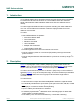
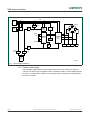
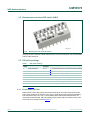
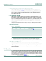
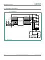
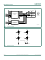
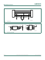
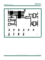
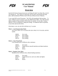
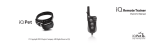
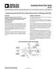
UM10573 PCA9633 demo board OM6276 Rev. 1 — 17 October 2012 User manual Document information Info Content Keywords LED driver, FET, I2C-bus Abstract The PCA9633 OM6276 demo board demonstrates the NXP Semiconductors PCA9633 Fast-mode Plus 4-bit I2C-bus LED driver IC UM10573 NXP Semiconductors PCA9633 demo board OM6276 Revision history Rev Date Description 1 20121017 first issue Contact information For more information, please visit: http://www.nxp.com For sales office addresses, please send an email to: [email protected] UM10573 User manual All information provided in this document is subject to legal disclaimers. Rev. 1 — 17 October 2012 © NXP B.V. 2012. All rights reserved. 2 of 16 UM10573 NXP Semiconductors PCA9633 demo board OM6276 1. Introduction The PCA9633 OM6276 demo board demonstrates the NXP Semiconductors PCA9633 Fast-mode Plus 4-bit I2C-bus LED driver IC. The PCA9633 controls four LEDs and through individual pulse width modulation (PWM) each LED show different levels of intensity. The board supports six different modes of operation including color wash and random color. The on-board Flash microcontroller is also user reprogrammable for endless variations of functionality. The board: • Has 6 Different Modes of Operation: – Auto Demonstration Mode – Color Wash Mode – Random Color Mode – User Color Mode – Multiple Card Chase Mode – Output Enable Control Mode • Includes high-current FET drivers for off board LED circuitry • Can be powered by either the on-board 9 V (DC) battery or through the external power connector • Can be daisy-chained with additional boards for synchronous control by a single I2C master 2. Description Figure 1 is a photograph of the PCA9633 (Philips legacy) demo board showing the PCA9633 chip (U2) and LPC925 microcontroller (U1) installed. Figure 3 shows a block diagram of the demo board. Figure 4 shows the board power and mode switch. The board can be powered by either the on-board 9 V (DC) battery on the underside of the board (Figure 2), or by an external power supply. There are 4 software programmable I2C addresses which allow the control of groups of devices with a single software command sequence. The board features: • 1 MHz and 30 mA output allows faster data updates and/or more capacitive buses • 4 individually controlled 25 mA open-drain or push-pull outputs OFF, ON, DIM, or DIM with Global Control for LED dimming/blinking • OE input pin also allows hardware dimming/blinking • Up to 7 address pins allows 128 I2C addresses • 4 software programmable I2C addresses allows controlling groups of devices with single software command sequence • If the battery is low, the red LED will flash every 3 seconds as a warning. UM10573 User manual All information provided in this document is subject to legal disclaimers. Rev. 1 — 17 October 2012 © NXP B.V. 2012. All rights reserved. 3 of 16 UM10573 NXP Semiconductors PCA9633 demo board OM6276 aaa-004224 Fig 1. Top view of PCA9633 OM6276 demo board Fig 2. UM10573 User manual Battery placement All information provided in this document is subject to legal disclaimers. Rev. 1 — 17 October 2012 © NXP B.V. 2012. All rights reserved. 4 of 16 UM10573 NXP Semiconductors PCA9633 demo board OM6276 ,&EXV 5- 6: SXOOXS 6: 9 5(* 5- GLIIXVHU , & %)5 % * 6: 2( % /('V 5 $ 02'( 6(/ /3& 0,&52 SXVKEXWWRQV 3&$ 6: $''5 /(' &75/5 ,&3 +'5 9 5(* FDEOH 6: SRZHU )(7 )(7 )(7 )(7 RIIERDUG/('VXSSRUW 6: RQRII 9 %$77 DDD Fig 3. Block diagram OM6276 2.1 Power connectivity The PCA9633 OM6276 demo board requires input power of 6 V (DC) to 9 V (DC) at 100 mA. This power may be supplied via the 9 V battery holder, or via the external power connector, J2. Take care to observe correct polarity when connecting an external power source to the board. UM10573 User manual All information provided in this document is subject to legal disclaimers. Rev. 1 — 17 October 2012 © NXP B.V. 2012. All rights reserved. 5 of 16 UM10573 NXP Semiconductors PCA9633 demo board OM6276 2.2 Board power and mode DIP switch (SW1) DDD Fig 4. Board power and mode DIP switch This DIP switch comprises 8 slider switches that connect board power, set slaved boards and set cable functions. 2.3 DIP switch settings Table 1. DIP switch settings Slider Function switch Switch position 1 1<>0 [1] board address input to processor and PCA9633 1<>0 [1] board address input to processor and PCA9633 [1] board address input to processor and PCA9633 2 board address 0 board address 1 Description 3 board address 2 1<>0 4 cable LED OE N<>Y 5 bus SDA pull-up enable N<>Y enable pull-up of the SDA signal on the cable 6 bus SCL pull-up enable N<>Y enable pull-up of the SCL signal on the cable connect the OE of the PCA9633 to the cable 7 cable power OFF/ON OFF/ON connect the battery to the cable 8 board power OFF/ON OFF/ON board power control [1] See Section 2.4. 2.3.1 Board power OFF/ON Slider switch 8 of the DIP switch turns power OFF/ON for the board. Switch the board power OFF whenever the board is not in use to avoid battery drain. Remove the battery from the board when not in use, to avoid battery drain should the OFF/ON switch be inadvertently switched ON. Place the battery in the holder with the contacts “away” from each other as a storage method (Figure 2). UM10573 User manual All information provided in this document is subject to legal disclaimers. Rev. 1 — 17 October 2012 © NXP B.V. 2012. All rights reserved. 6 of 16 UM10573 NXP Semiconductors PCA9633 demo board OM6276 2.3.2 Bus SDA pull-up enable and bus SCL pull-up enable Slider switches 5 and 6 (see Table 1) disable/enable the cable side pull-ups for the I2C-bus. These switches must be ON for the MASTER Board (0) and the LAST SLAVE board in the chain. All other boards between, must have these switches set to OFF. If there are only two boards connected (MASTER and SLAVE), both boards must have these switches set to ON. 2.3.3 Cable power OFF/ON Slider switch 7 enables the battery power connection to the RJ45 cable on pin 1 of the RJ45 Ethernet socket. It allows a single power source for the complete chain of boards when all the boards have this switch set to ON. When a chain of boards is utilized, use a single bench or wall power supply and remove the 9 V battery from each board. This action is necessary as the typical 9 V battery cannot supply enough current to power multiple boards. The input power requirements are: 6 V (DC) to 12 V (DC), 100 mA per board maximum. 2.4 Board selection Table 2. Board address SW3 SW2 SW1 Board Description ON ON ON 0 master (default)[1][2] ON ON OFF 1 slave 1 ON OFF ON 2 slave 2 ON OFF OFF 3 slave 3 OFF ON ON 4 slave 4 OFF ON OFF 5 slave 5 OFF OFF ON 6 slave 6 OFF OFF OFF 7 slave 7 [1] Only one board can be set as Master. [2] The MASTER board must be at one end of the Ethernet cable for proper operation of the I2C-bus. Subsequent SLAVE boards are not required to be in any certain order. Also, there may be gaps in the SLAVE board addresses (e.g., it is possible to have SLAVE Boards 2, 4, 6 and no SLAVE Board 3 or 5). 2.5 Off-board LED drivers The PCA9633 OM6276 demo board includes four NXP Semiconductors BSH112 high-current FET drivers for off-board LED circuitry. These devices, Q1 to Q4, are capable of switching up to 60 V at 300 mA. Their outputs are connected to solder pads L1 to L4 with adjacent 5 V and GND connections. They are connected as “low side” switches to ground configuration. 3. Operation On the DIP switch push slider switch 8 to the ON position. The LEDs will immediately flash and glow. To select a different mode of operation, press the MODE button (PB1). The LED will flash amber a number of times to denote which mode has been entered. Use the other three buttons (SELECT, PLUS, MINUS) to change the settings. The six different available modes of operation are described in Table 3. UM10573 User manual All information provided in this document is subject to legal disclaimers. Rev. 1 — 17 October 2012 © NXP B.V. 2012. All rights reserved. 7 of 16 UM10573 NXP Semiconductors PCA9633 demo board OM6276 If the battery is low, the red LED will flash every three seconds. Table 3. UM10573 User manual Modes Switch selection Action Mode 1: Auto demonstration First shows Mode 2 for 10 seconds, then shows Mode 3 for 10 seconds, and then repeats Mode next mode Select does nothing Plus does nothing Minus does nothing Mode 2: Color wash Goes through blends of different colors continuous Mode next mode Select toggle between smooth transitions and sharp transitions Plus does nothing Minus does nothing Mode 3: Random color Randomly shows different colors without blending transitions Mode next mode Select toggle between two color sets: darker and lighter Plus faster Minus slower Mode 4: User color Allows a color to be chosen by selecting the amount of each LED’s PWM output. It also selects the fifth group PWM that is used to dim or blink the combined colors at the same time Mode next mode Select select color PWM component: red, green, blue, amber or white; fifth group PWM flashes as that PWM is selected Plus more of that color component Minus less of that color component Mode 5: Multiple card chase Uses multiple cards and the group call feature of the PCA9633 to generate a chase pattern of 2 (yellow/red), 3 (yellow/red/green), or 4 (yellow/red/green/blue) colors. It can be done for up to 8 boards (master plus seven slave boards) connected via the RJ45 Ethernet sockets. Mode next mode Select select color PWM component: red, green, blue, amber or white; fifth group PWM flashes as that PWM is selected Plus more of that color component Minus less of that color component Mode 6: Output Enable control Demonstrates the OE control pin input that sets the LED outputs to high impedance. This mode changes the LED diffuser color to purple and blinks all LEDs at the same rate. Mode next mode All information provided in this document is subject to legal disclaimers. Rev. 1 — 17 October 2012 © NXP B.V. 2012. All rights reserved. 8 of 16 UM10573 NXP Semiconductors PCA9633 demo board OM6276 Table 3. UM10573 User manual Modes Switch selection Action Select selects frequency (duty cycle fixed at 50 %/50 %) or duty cycle (frequency fixed at XX) Plus faster frequency (double each push) or longer ON duty cycle Minus slower frequency (halves each push) or shorter ON duty cycle All information provided in this document is subject to legal disclaimers. Rev. 1 — 17 October 2012 © NXP B.V. 2012. All rights reserved. 9 of 16 UM10573 NXP Semiconductors PCA9633 demo board OM6276 4. Application information 4.1 Schematics 3% PLQXV 9&& .%,2&033 6(/ 6(/ 9&& 5 9&& 5 567Q 6(/ 5 6'$ 5 6&/ 3 8 3 5673 966 3/3&)'+ ;7$/3 76623 &/.287;7$/3 ,173 6'$,1723 6&/723 3&,1%.%, 3/86 3&,1$.%, 6(/ 3&,1%.%, 9%021 3&,1$.%, 3'$ 3&035().%, 9'' 3&/ 3&03.%, 02'( 37.%, /('21Q 37;' 7;' 35;' 5;' 6:.(<6367 3% 6:.(<6367 3% 6:.(<6367 3% 6:.(<6367 PLQXV SOXV VHO PRGH PLFURSURFHVVRU 9&& 53 Nȍ ,62 9,1 5 237,21$/%$77(5< 92/7$*(021,725,1* 86,1*$'&2)/3& 5 DDD Fig 5. Microprocessor UM10573 User manual All information provided in this document is subject to legal disclaimers. Rev. 1 — 17 October 2012 © NXP B.V. 2012. All rights reserved. 10 of 16 UM10573 NXP Semiconductors PCA9633 demo board OM6276 9 9 9'' $ $ 56'$ 6'$ 56&/ 6&/ $ /('21Q 8 3&$3: 76623 2( 966 $ 6(/ 5 $ 6(/ ȍ /(' / /(' / /(' / /(' / 5 ȍ 5 ȍ 6(/ $ 5 $ /('UHG /(' /('JUHHQ /(' /('EOXH /(' /('DPEHU = GLIIXVHU $7-% ȍ /('GULYHU ,&$''5 [&; 9 9'' 56'$ 6'$ 56&/ 6&/ *1' 8 3&$7.'1/ +9621 /(' /(' /(' /(' $/7/('GULYHU ,&$''5 [& Fig 6. /(' DDD On-board LED drivers / / 73 73 4 %6+ 4 %6+ / 73 73 4 %6+ 4 %6+ / RIIERDUG/('GULYHUV 73 9 73 DDD Fig 7. Off-board LED drivers UM10573 User manual All information provided in this document is subject to legal disclaimers. Rev. 1 — 17 October 2012 © NXP B.V. 2012. All rights reserved. 11 of 16 UM10573 NXP Semiconductors PCA9633 demo board OM6276 &21 &/('21Q 56'$ 56&/ 6:%$7 5- &21 5- ' %$7$75 DDD Fig 8. Con1/Con2 9 6'$ 56'$ 6; 5; 7; *1' Fig 9. 8 3%'3 9&& %)53:5 6< 6&/ 5< 56&/ 7< 9&& - 6&/ & ) 3&/ 6'$ 7;' 76623627 +($'(5[PP ,&EXIIHU ,&3KHDGHU 5;' 3'$ 567Q DDD IC2 buffer; ICP header UM10573 User manual All information provided in this document is subject to legal disclaimers. Rev. 1 — 17 October 2012 © NXP B.V. 2012. All rights reserved. 12 of 16 UM10573 NXP Semiconductors PCA9633 demo board OM6276 9&& 53 Nȍ,62 6 6(/ 6(/ 6(/ /('21Q &/('21Q 56'$ 56&/ 6:%$7 5 9 Nȍ 5 9 9 9,1 QF ' 9,1 5(* QF *1' QF 76623627 9UHJXODWRU %$7$75 8 7'$77'7 6:'3 QF QF Nȍ - 93 9&& &213,1 '1/ 93 *1' %+ *1' QF %+%&93& 9&& & ) 9 & ) 9 9&& & ) 9 9&& 9 & ) 5(* *1' *1' QF 62 9UHJXODWRU 9,1 9 7'$$7'7 LQSXWSRZHU 9,1 8 & ) 9 & ) 9 9 & ) 9 & ) 9 9&& & ) & ) DDD Fig 10. Input power UM10573 User manual All information provided in this document is subject to legal disclaimers. Rev. 1 — 17 October 2012 © NXP B.V. 2012. All rights reserved. 13 of 16 UM10573 NXP Semiconductors PCA9633 demo board OM6276 5. Abbreviations Table 4. UM10573 User manual Abbreviations Acronym Description DIP Dual In-line Package FET Field Effect Transistor I2C-bus Inter-Integrated Circuit bus LED Light Emitting Diode All information provided in this document is subject to legal disclaimers. Rev. 1 — 17 October 2012 © NXP B.V. 2012. All rights reserved. 14 of 16 UM10573 NXP Semiconductors PCA9633 demo board OM6276 6. Legal information 6.1 Definitions Draft — The document is a draft version only. The content is still under internal review and subject to formal approval, which may result in modifications or additions. NXP Semiconductors does not give any representations or warranties as to the accuracy or completeness of information included herein and shall have no liability for the consequences of use of such information. 6.2 Disclaimers Limited warranty and liability — Information in this document is believed to be accurate and reliable. However, NXP Semiconductors does not give any representations or warranties, expressed or implied, as to the accuracy or completeness of such information and shall have no liability for the consequences of use of such information. NXP Semiconductors takes no responsibility for the content in this document if provided by an information source outside of NXP Semiconductors. In no event shall NXP Semiconductors be liable for any indirect, incidental, punitive, special or consequential damages (including - without limitation - lost profits, lost savings, business interruption, costs related to the removal or replacement of any products or rework charges) whether or not such damages are based on tort (including negligence), warranty, breach of contract or any other legal theory. Notwithstanding any damages that customer might incur for any reason whatsoever, NXP Semiconductors’ aggregate and cumulative liability towards customer for the products described herein shall be limited in accordance with the Terms and conditions of commercial sale of NXP Semiconductors. Right to make changes — NXP Semiconductors reserves the right to make changes to information published in this document, including without limitation specifications and product descriptions, at any time and without notice. This document supersedes and replaces all information supplied prior to the publication hereof. Suitability for use — NXP Semiconductors products are not designed, authorized or warranted to be suitable for use in life support, life-critical or safety-critical systems or equipment, nor in applications where failure or malfunction of an NXP Semiconductors product can reasonably be expected to result in personal injury, death or severe property or environmental damage. NXP Semiconductors and its suppliers accept no liability for inclusion and/or use of NXP Semiconductors products in such equipment or applications and therefore such inclusion and/or use is at the customer’s own risk. design. It is customer’s sole responsibility to determine whether the NXP Semiconductors product is suitable and fit for the customer’s applications and products planned, as well as for the planned application and use of customer’s third party customer(s). Customers should provide appropriate design and operating safeguards to minimize the risks associated with their applications and products. NXP Semiconductors does not accept any liability related to any default, damage, costs or problem which is based on any weakness or default in the customer’s applications or products, or the application or use by customer’s third party customer(s). Customer is responsible for doing all necessary testing for the customer’s applications and products using NXP Semiconductors products in order to avoid a default of the applications and the products or of the application or use by customer’s third party customer(s). NXP does not accept any liability in this respect. Export control — This document as well as the item(s) described herein may be subject to export control regulations. Export might require a prior authorization from competent authorities. Evaluation products — This product is provided on an “as is” and “with all faults” basis for evaluation purposes only. NXP Semiconductors, its affiliates and their suppliers expressly disclaim all warranties, whether express, implied or statutory, including but not limited to the implied warranties of non-infringement, merchantability and fitness for a particular purpose. The entire risk as to the quality, or arising out of the use or performance, of this product remains with customer. In no event shall NXP Semiconductors, its affiliates or their suppliers be liable to customer for any special, indirect, consequential, punitive or incidental damages (including without limitation damages for loss of business, business interruption, loss of use, loss of data or information, and the like) arising out the use of or inability to use the product, whether or not based on tort (including negligence), strict liability, breach of contract, breach of warranty or any other theory, even if advised of the possibility of such damages. Notwithstanding any damages that customer might incur for any reason whatsoever (including without limitation, all damages referenced above and all direct or general damages), the entire liability of NXP Semiconductors, its affiliates and their suppliers and customer’s exclusive remedy for all of the foregoing shall be limited to actual damages incurred by customer based on reasonable reliance up to the greater of the amount actually paid by customer for the product or five dollars (US$5.00). The foregoing limitations, exclusions and disclaimers shall apply to the maximum extent permitted by applicable law, even if any remedy fails of its essential purpose. Translations — A non-English (translated) version of a document is for reference only. The English version shall prevail in case of any discrepancy between the translated and English versions. Applications — Applications that are described herein for any of these products are for illustrative purposes only. NXP Semiconductors makes no representation or warranty that such applications will be suitable for the specified use without further testing or modification. 6.3 Customers are responsible for the design and operation of their applications and products using NXP Semiconductors products, and NXP Semiconductors accepts no liability for any assistance with applications or customer product I2C-bus — logo is a trademark of NXP B.V. UM10573 User manual Trademarks Notice: All referenced brands, product names, service names and trademarks are the property of their respective owners. All information provided in this document is subject to legal disclaimers. Rev. 1 — 17 October 2012 © NXP B.V. 2012. All rights reserved. 15 of 16 UM10573 NXP Semiconductors PCA9633 demo board OM6276 7. Contents 1 2 2.1 2.2 2.3 2.3.1 2.3.2 2.3.3 2.4 2.5 3 4 4.1 5 6 6.1 6.2 6.3 7 Introduction . . . . . . . . . . . . . . . . . . . . . . . . . . . . 3 Description . . . . . . . . . . . . . . . . . . . . . . . . . . . . . 3 Power connectivity . . . . . . . . . . . . . . . . . . . . . . 5 Board power and mode DIP switch (SW1) . . . . 6 DIP switch settings . . . . . . . . . . . . . . . . . . . . . . 6 Board power OFF/ON. . . . . . . . . . . . . . . . . . . . 6 Bus SDA pull-up enable and bus SCL pull-up enable. . . . . . . . . . . . . . . . . . . . . . . . . . . . . . . . 7 Cable power OFF/ON . . . . . . . . . . . . . . . . . . . . 7 Board selection . . . . . . . . . . . . . . . . . . . . . . . . . 7 Off-board LED drivers. . . . . . . . . . . . . . . . . . . . 7 Operation . . . . . . . . . . . . . . . . . . . . . . . . . . . . . . 7 Application information. . . . . . . . . . . . . . . . . . 10 Schematics . . . . . . . . . . . . . . . . . . . . . . . . . . . 10 Abbreviations . . . . . . . . . . . . . . . . . . . . . . . . . . 14 Legal information. . . . . . . . . . . . . . . . . . . . . . . 15 Definitions . . . . . . . . . . . . . . . . . . . . . . . . . . . . 15 Disclaimers . . . . . . . . . . . . . . . . . . . . . . . . . . . 15 Trademarks. . . . . . . . . . . . . . . . . . . . . . . . . . . 15 Contents . . . . . . . . . . . . . . . . . . . . . . . . . . . . . . 16 Please be aware that important notices concerning this document and the product(s) described herein, have been included in section ‘Legal information’. © NXP B.V. 2012. All rights reserved. For more information, please visit: http://www.nxp.com For sales office addresses, please send an email to: [email protected] Date of release: 17 October 2012 Document identifier: UM10573