1
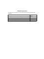
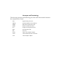
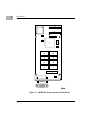
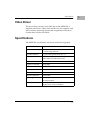
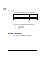
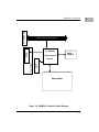
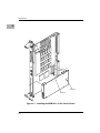
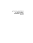
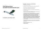
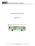
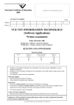
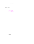
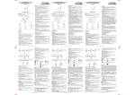
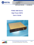
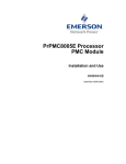
MPMC301
Graphics Module
Installation Manual
PMC301-1A/IH1
Notice
While reasonable efforts have been made to assure the accuracy of this document,
Motorola, Inc. assumes no liability resulting from any omissions in this document,
or from the use of the information obtained therein. Motorola reserves the right to
revise this document and to make changes from time to time in the content hereof
without obligation of Motorola to notify any person of such revision or changes.
No part of this material may be reproduced or copied in any tangible medium, or
stored in a retrieval system, or transmitted in any form, or by any means, radio,
electronic, mechanical, photocopying, recording or facsimile, or otherwise,
without the prior written permission of Motorola, Inc.
It is possible that this publication may contain reference to, or information about
Motorola products (machines and programs), programming, or services that are
not announced in your country. Such references or information must not be
construed to mean that Motorola intends to announce such Motorola products,
programming, or services in your country.
Restricted Rights Legend
If the documentation contained herein is supplied, directly or indirectly, to the U.S.
Government, the following notice shall apply unless otherwise agreed to in
writing by Motorola, Inc.
Use, duplication, or disclosure by the Government is subject to restrictions as set
forth in subparagraph (c)(1)(ii) of the Rights in Technical Data and Computer
Software clause at DFARS 252.227-7013.
Motorola, Inc.
Computer Group
2900 South Diablo Way
Tempe, Arizona 85282
Preface
The PMC Graphics Module Installation Manual describes the installation,
components, and conÞgurations of the board itself. The document should be used
by anyone who wants general as well as technical information about the PMC
Graphics module.
Motorola¨ and the Motorola symbol are registered trademarks of Motorola, Inc.
All other products mentioned in this document are trademarks or registered
trademarks of their respective holders.
© Copyright Motorola, Inc. 1997
All Rights Reserved
Printed in the United States of America
October 1997
Related Documentation
The publications listed below provide additional information pertinent to this
document.
Document Title
PCI Local Bus SpeciÞcation Rev 2.0; PCI Special Interest Group
Common Mezzanine Card SpeciÞcation; IEEE
PCI Mezzanine Card SpeciÞcation; IEEE
CL-GD5446 Technical Reference Manual
Publication
Number
PCI Rev 2.0
P1386 Draft 1.5
P1386.1 Draft 1.5
Rev 2.0
Acronyms and Terminology
The following acronyms and terminology are often used in this manual instead of
the complete title or name:
DAC
DRAM
MPMC
MTBF
PCI
PMC
PPC
SVGA
VAFC
VGA
Digital Analog Converter
Dynamic Random Access Memory
Motorola PCI Mezzanine Card
Mean Time Between Failure
Peripheral Component Interface
PCI Mezzanine Card
Power PC
Super Video Graphics Adapter
VESA Advanced Feature Connector
Video Graphics Adapter
Safety Summary
Safety Depends On You
The following general safety precautions must be observed during all phases of operation, service, and
repair of this equipment. Failure to comply with these precautions or with speciÞc warnings elsewhere in
this manual violates safety standards of design, manufacture, and intended use of the equipment.
Motorola, Inc. assumes no liability for the customer's failure to comply with these requirements.
The safety precautions listed below represent warnings of certain dangers of which Motorola is aware. You,
as the user of the product, should follow these warnings and all other safety precautions necessary for the
safe operation of the equipment in your operating environment.
Ground the Instrument.
To minimize shock hazard, the equipment chassis and enclosure must be connected to an electrical ground.
The equipment is supplied with a three-conductor ac power cable. The power cable must be plugged into
an approved three-contact electrical outlet. The power jack and mating plug of the power cable meet
International Electrotechnical Commission (IEC) safety standards.
Do Not Operate in an Explosive Atmosphere.
Do not operate the equipment in the presence of ßammable gases or fumes. Operation of any electrical
equipment in such an environment constitutes a deÞnite safety hazard.
Keep Away From Live Circuits.
Operating personnel must not remove equipment covers. Only Factory Authorized Service Personnel or
other qualiÞed maintenance personnel may remove equipment covers for internal subassembly or
component replacement or any internal adjustment. Do not replace components with power cable
connected. Under certain conditions, dangerous voltages may exist even with the power cable removed. To
avoid injuries, always disconnect power and discharge circuits before touching them.
Do Not Service or Adjust Alone.
Do not attempt internal service or adjustment unless another person capable of rendering Þrst aid and
resuscitation is present.
Use Caution When Exposing or Handling the CRT.
Breakage of the Cathode-Ray Tube (CRT) causes a high-velocity scattering of glass fragments (implosion).
To prevent CRT implosion, avoid rough handling or jarring of the equipment. Handling of the CRT should
be done only by qualiÞed maintenance personnel using approved safety mask and gloves.
Do Not Substitute Parts or Modify Equipment.
Because of the danger of introducing additional hazards, do not install substitute parts or perform any
unauthorized modiÞcation of the equipment. Contact your local Motorola representative for service and
repair to ensure that safety features are maintained.
Dangerous Procedure Warnings.
Warnings, such as the example below, precede potentially dangerous procedures throughout this manual.
Instructions contained in the warnings must be followed. You should also employ all other safety
precautions which you deem necessary for the operation of the equipment in your operating environment.
!
Warning
Dangerous voltages, capable of causing death, are
present in this equipment. Use extreme caution when
handling, testing, and adjusting.
All Motorola printed wiring boards are manufactured by UL-recognized
manufacturers, with a ßammability rating of 94V-0.
!
Warning
This equipment generates, uses, and can radiate electromagnetic energy. It may cause or be susceptible to
electro-magnetic interference (EMI) if not installed and
used in a cabinet with adequate EMI protection.
European Notice: Board products with the CE marking comply with the
EMC Directive (89/336/EEC). Compliance with this directive implies
conformity to the following European Norms:
EN55022 (CISPR 22) Radio Frequency Interference
EN50082-1 (IEC801-2, IEC801-3, IEC801-4) Electromagnetic Immunity
The product also fulÞlls EN60950 (product safety) which is essentially the
requirement for the Low Voltage Directive (73/23/EEC).
This board product was tested in a representative system to show
compliance with the above mentioned requirements. A proper installation
in a CE-marked system will maintain the required EMC/safety
performance.
Contents
Product Overview 1-1
Graphics PMC Features 1-1
Video Driver 1-3
SpeciÞcations 1-3
Operating Environment 1-4
MPMC301 Architecture 1-4
Introduction 2-1
Installation and ConÞguration Tasks 2-1
Packaging 2-1
Electro-static Discharge Precautions 2-2
Installing the MPMC301 on the Carrier Board 2-2
Starting the MPMC301 2-5
1Introduction
1
Product Overview
The MPMC301 Graphics PCI Mezzanine Card (PMC) is a single
wide board with an SVGA graphics interface. The graphics
interface is implemented with a Cirrus Logic CL-GD5446 graphics
accelerator, which supports a pixel clock rate up to 135MHz.
Internal palette DAC may be configured for industry-standard
VGA modes of 16 or 256 color, or extended to high and true color
modes of 32K or 16.7 million colors. Resolution up to 1280 x 1024
can also be supported depending on the color and bits/pixel
modes.
Graphics PMC Features
The Graphics PMC has the following features:
❏
Single-wide PMC module
❏
Cirrus 5446 graphics controller
❏
SVGA graphics
❏
Front panel I/O for graphics monitor
❏
1280 x 1024 resolution, 16 or 256 colors
❏
4MB of Video DRAM
❏
ANSI X3T12 standards compliant
❏
Compliance to PCI local bus specification (Revision 2.0)
Figure 1-1 shows the MPMC301 component layout and front panel.
1-1
1
Introduction
Figure 1-1. MPMC301 Board Layout and Front Panel
1-2
Video Driver
Video Driver
The device driver for the Cirrus 5446 chip on the MPMC301 is
supplied with AIX 4.1.4 R4 or later releases.It is also supplied with
select real-time operating systems and or application extensions.
Contact those vendors for details
Specifications
The MPMC301 specifications are shown in the following table:
Form Factor
Single-wide PCI Mezzanine Card (PMC)
Dimensions
2.9 inches wide (74 mm)
5.9 inches long (149 mm)
Host Bus Interface
PCI Local Bus SpeciÞcation, Rev 2.1
IEEE Compliance
IEEE P1386 Common Mezzanine Card and
IEEE P1386.1 PCI Mezzanine Card
Host Data Transfer
32-bit Bus Master DMA transfers to 132MB/s
Graphics Controller
Cirrus 5446
Bus Structure
32-bit PCI Local Bus
Memory
4MB of Video Dram
Monitor Interface
SVGA
Monitor Connector
3 Row DB15
Operating Power
500 ma typical
750 ma maximum
Reliability
190,509 hours mean time between failure;
107,681 hours at 95% conÞdence
1-3
1
1
Introduction
Operating Environment
The MPMC301 requires the following operating environment:
Operating temperature
0û to 55ûC
Storage temperature
-40û to 85ûC
Operating humidity, non-condensing
10 to 80%
Storage humidity, non-condensing
5 to 95%
Forced air cooling is not required when the ambient temperature is
below 40 degrees C. Above 40 degrees C, forced air cooling is
required.
The voltage and current requirements for the MPMC301 are:
+5V
290 mA typical
440 mA maximum
+12V
None
-12V
None
MPMC301 Architecture
Figure 1-2 shows a block diagram of the MPMC301.
1-4
64-bit PMC Slot
MPMC301 Architecture
32MHz 32/64-bit PCI Local Bus
SVGA
CL-GD5446
SVGA Graphics
BIOS
EPROM
VAFC
Front Panel
Interface
DRAM ARRAY
Figure 1-2. MPMC301 Graphics Block Diagram
1-5
1
1
Introduction
1-6
2Installation
2
Introduction
This chapter contains instructions for installing the MPMC301
Graphics module onto a carrier board.
Installation and Configuration Tasks
Perform the following tasks to install and configure the MPMC301:
❏
Install the MPMC301 on the carrier board per the instructions
in ÒInstalling the MPMC301 on the Carrier BoardÓ in this
chapter.
❏
Connect the monitor cable per the instructions in the system
chassis manual.
❏
Power-up the system per the instructions in the system
chassis manual.
❏
Reboot the system.
Packaging
The MPMC301 is packed in an anti-static package to protect it from
any static discharge. Observe standard handling practices of static
sensitive equipment.
2-1
Installation
2
Electro-static Discharge Precautions
Use ESD
Wrist Strap
Motorola strongly recommends that you use an antistatic wrist
strap and a conductive foam pad when installing the MPMC301.
Electronic components can be extremely sensitive to electro-static
discharge (ESD). After removing the board from the protective
wrapper, place it component side up on a grounded, static-free
surface. Do not slide the board over any surface.
Installing the MPMC301 on the Carrier Board
Follow these steps to install the MPMC301 on the carrier board:
1. Place an ESD strap on your wrist and attach the grounding
line end of the ESD strap to the chassis as a ground. The ESD
strap must be secured to your wrist and to ground
throughout the procedure.
2. Remove the carrier board from the system chassis.
3. Lay the carrier board on a level surface with the PMC
connectors facing you.
4. Remove the PMC slot filler panel from the carrier boardÕs
front panel.
5. Remove the screws from the stand-offs on the component
side of the MPMC301.
6. Turn the MPMC301 component-side down, and position it
above the carrier board as shown in Figure 2-1 (an
MVME2600x carrier board is shown).
!
Avoid touching areas of integrated circuitry; static
discharge can damage these circuits.
Caution
Note
2-2
Refer to Figure 2-1 when performing steps 7, 8, and 9.
Installing the MPMC301 on the Carrier Board
7. Align the keying hole and connectors P11 and P12 on the
MPMC301 over the keying pin and the PMC connectors on
the carrier board.
8. Gently seat the MPMC301 onto the carrier board.
9. Turn the carrier board component-side down, and fasten the
four screws through the carrier board into the stand-offs on
the PMC.
10. Install the carrier board in the system chassis.
2-3
2
Installation
2
J12
P12
P11
J11
GUIDE HOLE
GUIDE PIN
Figure 2-1. Installing the MPMC301 on the Carrier Board
2-4
Starting the MPMC301
Starting the MPMC301
2
After installing the MPMC301 and attaching the cable, turn the
power on as directed in the system manual. The MPMC301 should
power-up automatically.
During the initialization sequence of PPCBug, it scans for attached
devices. If PPCBug locates a keyboard and MPMC301, PPCBug
then uses MPMC301 for output and the keyboard for input.
If PPCBug does not find both the keyboard and the MPMC301,
PPCBug utilizes the console port for input/output.
2-5
Installation
2
2-6