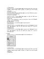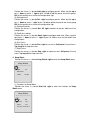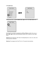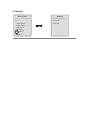
1
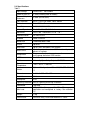
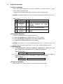
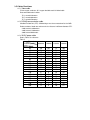
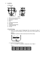
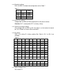
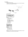
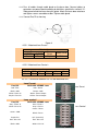
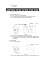
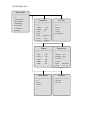
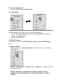
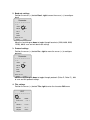
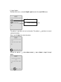
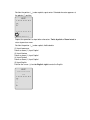
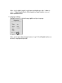
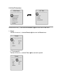
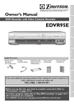
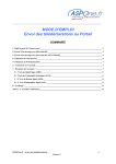
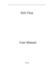
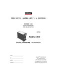
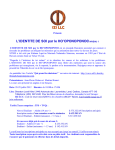
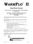
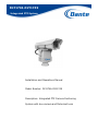
DLY1746-DLY1749
Integrated PTZ System
Installation and Operations Manual
Model Number: DLY1746-DLY1749
Description: Integrated PTZ Camera Positioning
System with box camera and Motorized Lens
Pan Tilt Camera Positioning System with Camera and
Motorized Lens
User Manual
Functions & Installation
Thanks for purchasing our product. Prior to installation and use of this product,
please read this manual carefully.
Features and specifications described in this manual are subject to change without
further notice. Please contact us or legal distributors if you have any questions
which are not included in this manual.
Content
1. IMPORTANT SAFEGUARDS AND WARNINGS 3
1.1
WARNING
3
1.2
CAUTION
3
2. INTRODUCTION
4
2.1
APPLICATION
4
2.2
GLOSSARY
4
2.3
SPECIFICATIONS
5
3. INSTALLATION PROVISIONS
7
3.1
BEFORE INSTALLATION
7
3.2
INSTALLATION PERSONNEL
7
3.3
MOUNTING PLACE
7
3.4
TOOLS FOR INSTALLATION
7
3.5
CABLES PROVISIONS
8
4. INSTALLATION
9
4.1
STRUCTURE
9
4.2
INITIAL SETTINGS
9
4.3
INSTALLATION
5. APPENDIX
11
15
5.1
LENS VOLTAGE ADJUSTMENT
5.2
LENS INSTALLATION
16
16
5.3
OSD MENU
18
1.
Important Safeguards and Warnings
1.1 Warning
1.1.1 Prior to installation and use of this product, read this user manual. Keep this manual.
1.1.2 The WARNINGS in this manual should be observed. Follow all instructions.
1.1.3 Turn off the power before cleaning the product. Don’t use liquid cleaners or aerosol
cleaners. Only use wet-cloth for cleaning.
1.1.4 Only use attachments/accessories specified in this manual.
1.1.5 Use only with the power supply specified in this manual.
1.1.6 Carefully protect all cables including power, video and connectors.
1.1.7 Please install arrester to avoid lighting/surge.
1.1.8 To avoid fire and electric shock, don’t use excessive long and overload cables.
1.1.9 Servicing is required when the product has been damaged in any way, such as liquid
has been spilled or objects have fallen into the product.
1.1.10 Don’t install the product onto unstable installation location. Use only installation
methods and materials capable of supporting four times the maximum specified load.
1.1.11 Don’t install, use or store the product in flammable and explosive place.
1.1.12 Don’t install or use the product in places exposed to excessive moisture, dust or
smoke. Keep the product away from heat source.
1.1.13 Don’t disassemble the product for servicing. Contact us or legal distributors.
1.1.14 Always turn off power and contact us or legal distributors if abnormal smoke occurs.
1.1.15 Servicing is required in any case of the following situations, contact us or legal
distributors:
A. Power supply cord or communication cable has been damaged
B. Incorrect power supply or input voltage
C. The product has been dropped or the cover has been damaged
D. Abnormal functions occur
E. The product doesn’t work by following this manual
1.1.16 Only use replacement parts recommended by company.
1.2 Caution
1.2.1
1.2.2
1.2.3
1.2.4
1.2.5
Avoid stress, vibration, steeping during transportation, storage and installation.
Keep the product away from magnetic field
Turn off the power before moving or re-installing the product
Don’t block any ventilation openings.
Company will be not in charge of the troubles due to unauthorized servicing. Please
contact us or legal distributors if the product doesn’t work well
1.2.6 Never expose the product to sunlight or harmful rays directly whatever use or nonuse.
Fatal damage to the CCD or internal circuit will be caused
1.2.7 Actions like water-proof, moisture-proof and dust-proof are needed in the case of
outdoor application.
Attention: To avoid short circuit, please ISOLATE all exposed cables from
Pan/Tilt to Housing before putting power to Pan/Tilt.
2.
Introduction
2.1 Application
2.1.1 As a high-end security surveillance product, Outdoor High-Duty Variable Speed Pan/Tilt
has construction of high-strength aluminum alloy frame and modified plastic cover. It
features anti-wind design, power off protection (self-lock) and smooth motion. It also
features variable speed, 360 degrees continuous movement, auto scan, auto cruise,
keep watch and OSD menu…etc. This Pan/Tilt is specially used for surveillance in
far-field, like application in field of fire-fighting in forest, coast and border, bridges over
sea or river and freeway…etc.
2.2 Glossary
2.2.1 Preset
Programmed video scene, based on a specific pan, tilt, zoom and focus
settings, and stored in domes.
2.2.2 Auto Scan
Allows the dome to continuously pan between the scan limits. The scan
limits are two points around the dome’s pan axis, which define a
surveillance area. The Auto Scan speed is programmable.
2.2.3 Auto Cruise
Add the preset points into cruise group. Switch to and check the preset
points in order by specified dwell time. The dwell time is programmable.
2.2.4 Keep Watch
Return the dome to a specified preset position at a fixed time after ending
manual operation. Keep watch functions to scan, cruise, pattern a specified
route
2.2.5 OSD Menu
On Screen Display Menu laid out on video signal.
Attention: OSD Menu can be operated by keyboard to control the Pan/Tilt
implement functions specified in menu.
2.3 Specifications
Table 1
Input Voltage
24VAC±25%
50 Hz/60Hz
Power of Pan/Tilt
≤ 85W(including 35W for heater)
Power Output for
≤ 85W (AC24V/3.5A)
Enclosure
Lens Interface
6VDC~12VDC for Zoom, Focus control
Protocol
Pelco D/Pelco P
Baud Rate
2400/4800/9600/19200
Manual Speed
Pan:0.01~12 °/s;Tilt:0.01~8 °/s
Movement
Pan:0~360 ° continuous;Tilt:-45 °~45 °
Communication
RS-485/RS-422
Protocol
Pelco D/Pelco P
Baud Rate
2400/4800/9600/19200
Preset
Up to 80
Auto Scan
Up to 5 lines, based on OSD function
Up to 8 groups, based on OSD function. Up to 80
presets in a group.
Programmed a preset, an auto scan line or an auto
cruise group, based on OSD function
Available
Auto Cruise
Keep Watch
OSD menu
AUX
Operation
Temperature
Heater
4 Normally Open Relay Outputs, 30VDC/2A
.-35℃~+65℃, ≤ 90%RH
Optional Configuration. ON:
8℃±5℃/OFF: 20℃±5
℃
Dimensions
L x W x H: 339 ×196 ×371mm
Installation
Outdoor
Waterproof
IP66
Lightning Protection Built-in Lightning and Surge Protection
Load Mode
Max Load
Top Load
43Kg (With tilt range -45°~225°. Tilt range is
adjustable and configured at factory. See attention
※)
Weight
17Kg
Construction
Aluminum Alloy Frame and Modified PC Cover
※Attention:
1 Top load: Tilt range is able to be adjustable and should be configured at factory.
Tilt Range
-30°~210°
-45°~225°
-60°~240°
-75°~255°
Maximum Load
55Kg
43Kg
32Kg
30kg
2 Call Preset 98 to run Auto Cruise, Group 1.
3 Call Preset 99 to run Auto Scan, Line 1.
4 Up to 5 Auto Scan and 8 Auto Cruise operated by OSD menu
※Attention:
Power supply is recommended at least 200W for normal work of pan tilt,
housing, camera, lens and heaters
3.
Installation Provisions
3.1 Before installation
Unpack the product heeding all accessories specified in the checklist (Table 2), please
contact vendor if anything missed.
Carefully keep the original material after unpacking in case of shipping it back.
Attention: Accidental damage will occur by not using original material and cause extra cost.
Table 2 Checklist
#
1
2
3
4
Accessories
Qty
User Manual
1
Connection
Tube
1
Protect cables from Pan/Tilt to
Housing
designed
for
surge
protection
3
Fix Pan/Tilt to mounting place
1
Template
pattern
Screws:
M8X45
Mounting
template
Remark
for
mounting
holes
3.2 Installation Personnel
Installation should be done only by qualified personnel:
3.2.1 Basic knowledge and installation skills of CCTV system.
3.2.2 Basic knowledge and operation skills of low voltage route.
3.2.3 Capability of understanding this user manual.
Attention: This manual is for use by qualified personnel only. To reduce the risk of any
damage, never disassemble the product or loosen screws except qualified personnel.
3.3 Mounting place
3.3.1 The mounting place should be capable of supporting the space of the unit
with all accessories (See dimensions in Table 3 for reference)
Table 3 Dimensions
Dimensions
L x W x H: 339 ×196 ×371mm
3.3.2 The mounting place should be capable of supporting 4 times the weight of
the unit with all accessories (See weight in Table 4 for reference).
Table 4 Weight
Total Weight
60Kg(17Kg for Pan/Tilt, 43Kg for load)
3.4 Tools for installation
Shifting wrench, cross head screwdriver, inner hex wrench, and wire stripper.
3.5 Cables Provisions
3.5.1 Video cable
75ohm copper conductor, 95% copper braided coaxial shielded cable
Recommended model number:
75-3, around 220 meters
75-5, around 300 meters
75-7, around 450 meters
3.5.2 RS-485 communication cable
Shielded Twisted Pair (STP). Shielded layer must be connected well to the GND.
Reference data of baud rate and transmission distance in 0.56mm diameter STP:
2.400, around 1,800 meters
4,800, around 1,200 meters
9,600, around 800 meters
3.5.3 24VAC power cable
Data in Table 5 for reference
Table 5
Diameter
Distance (meter)
Power (Watt)
30
40
50
60
70
80
90
100
110
120
130
140
150
160
170
180
190
200
0.80mm 1.00mm 1.25mm 2.00mm
28
21
17
14
12
10
9
8
7
7
6
6
5
5
4
4
4
4
45
34
27
22
19
17
15
13
12
11
10
9
9
8
7
7
7
6
72
54
43
36
31
27
24
21
19
17
16
15
14
13
12
11
11
10
183
137
110
91
78
68
61
55
49
45
42
39
36
34
32
30
28
27
4.
Installation
4.1 Structure
1.
2.
3.
4.
5.
6.
7.
8.
9.
Figure 1
M5 inner hex screws (6 totally)
Housing mounting plate
Right arm
Base
Cable gland (to outside)
Base door
Cable gland (to housing)
Configuration Door
Left arm
4.2 Initial Settings
4.2.1 Loosen the screws around Configuration Door and remove the door. 2
switches on the circuit board in the Pan/Tilt cover are for initial settings. See
Figure 2
Attention: Assemble the camera cover back after initial settings.
Address
Select
SW2
SW1
ON
ON
1 2 3 4 5 6 7 8
1 2 3 4 5 6 7 8
Fast
R2
Figure 2
4.2.2 Communication protocol settings
Bit 1, 2, 3, 4 of SW1 is for protocols configuration refer to Table 6
Table 6
Pelco-P
Pelco-D
Bit 1
OFF
ON
Bit 2
ON
ON
Bit 3
OFF
OFF
Bit 4
OFF
OFF
4.2.3 Baud rate settings
Bit 5, 6 of SW1 is for baud rate configuration refer to Table 7
Table 7
Bit 5
Bit 6
OFF
ON
OFF
ON
OFF
OFF
ON
ON
Baud
Rate
2400
4800
9600
19200
4.2.4 Preset lens settings
Configure Bit 7 of SW1 to ON for motorized lens with preset function.
Attention: Bit 7 is configured to OFF as factory settings.
4.2.5 Terminal resistance settings
Only configure Bit 8 of SW1 to ON if the dome is at the terminal of control
bus, the 120 ohm resistance will be connected.
4.2.6 ID settings
SW2 is for setting ID in binary coding (See Table 8). Bit 1 to Bit 8 are
available.
Table 8
ID
Bit 1
Bit 2
Bit 3
Bit 4
Bit 5
Bit 6
Bit 7
Bit 8
1
ON
OFF
OFF
OFF
OFF
OFF
OFF
OFF
2
OFF
ON
OFF
OFF
OFF
OFF
OFF
OFF
3
ON
ON
OFF
OFF
OFF
OFF
OFF
OFF
4
OFF
OFF
ON
OFF
OFF
OFF
OFF
OFF
OFF
ON
OFF
OFF
OFF
OFF
OFF
5
ON
6
OFF
ON
ON
OFF
OFF
OFF
OFF
OFF
7
ON
ON
ON
OFF
OFF
OFF
OFF
OFF
8
OFF
OFF
OFF
ON
OFF
OFF
OFF
OFF
……
…………………………………………………………………
254
OFF
ON
ON
ON
ON
ON
ON
ON
255
ON
ON
ON
ON
ON
ON
ON
ON
4.2.7 Adjust voltage to Lens
See section 5.1.
4.3 Installation
4.3.1 Connect Pan/Tilt to system
Loosen the screws around base door and remove the door. Slide power
board off base through guide. See Figure 3
(1)
(2)
Figure 3
(1) 7-pin connector
Definition:
V+: Video output +
V-: Video output grand
GND: Groud
RX-: RS485-B/ RS422-RXRX+: RS485-A/ RS422-RX+
TX-:RS422-TXTX+:RS422-TX+
(2) 4-pin connector
Definition:
AC24V: Input 24VAC
AC24V: Input 24VAC
EGND: Surge Ground
Attention: The dome should be connected to the ground reliably for effective
surge protection, refer to relevant national standard.
4.3.2 Pass all cables through cable gland on the base door. Connect cables to
connectors on power board according to definitions specified in section 4.3.1.
Slide power board into base along the guide. Attach the base door onto base
and tighten screws around base door. Tighten cable gland.
4.3.3 Connect Pan/Tilt to housing
Figure 4
4.3.3.1 Motorized Lens Preset –
Motorized lens
Power
Focus
Preset
+3.3VDC
- 3.3VDC
Red
Black
Purple
Zoom Preset
White
4.3.3.2 Motorized Lens Control –
+12VDC
Red
GND
Black
Lens
Zoom
Focus
Gray
White
Iris
Purple
Com
Green
4.3.3.2.1 Connection between Pan Tilt and Motorized Lens
Lens Preset
Pan/tilt
DLR2136-15300P Lens
Red--VDC
Pink--Power
Black--GND
Brown--GND
White--Zoom In
Purple--Focus In
White--Zoom Output
Yellow--Focus Output
Lens Preset
Lens control
Pan/tilt
DLR2136-15300P Lens
Gray--Zoom In
White--Focus In
Blue—Zoom+
Gray—Focus+
Green—Zoom-
Green--COM
Black—Focus-
Purple-Iris
N/C (Auto Iris)
Red--DC+12V
Red--DC+12V
Black--GND
White--DC-12V
Lens Control
4.3.3.3 Aux cables
Definition:
Housing Power 24VAC
Aux 1
Aux 2
Yellow
Yellow
White White Orange Orange
Aux 3
Blue Blue
Aux 4
Gray Gray
4.3.3.4 Video cable
4.3.4 Install housing to Pan/Tilt
4.3.4.1 Pan Tilt to Plate are recommended
4.3.4.2 Remove housing mounting plate. Attach housing to this plate.
4.3.4.3 Mounting holes pattern on housing mounting plate
Housing mounting plate
Mounting
pattern
holes
Figure 5
4.3.4.4 Re-install mounting plate back to left and right arms
4.3.4.5 Pass all cables through connection tube (attached in shipping box) for
surge protection. Connect 2 ends of this tube to cable gland on pan/tilt
and housing.
4.3.5 Mount Pan/Tilt
4.3.5.1 Mounting template
Mounting
holes
Figure 6
4.3.5.2 Using the template (attached) to mark the fastener positions on the
mounting surface and prepare holes. See Figure 7
Figure 7
4.3.5.3 Mount Pan/Tilt to prepared place by M8X45 screws (attached in
shipping box)
5.
Appendix
5.1 Lens voltage adjustment
Address
Select
SW2
SW1
ON
ON
1 2 3 4 5 6 7 8
1 2 3 4 5 6 7 8
Fast
R2
R2 is available for adjusting voltage to lens. Default value of R2 is DC10V±1V. Rotate
button on R2 counter-clockwise is to increase voltage.
Attention: Only qualified person is able and allowed to adjust this parameter.
Errors by wrong operation will cause abnormal work
5.2 Lens Installation
Installation and Debugging
a. Open the front and back lid
b. mount the lens to the camera, then clockwise rotate the lens to the appropriate
position
c. Connect the electric wires following pg. 12, then turn on the power source.
d. Open the iris。
e. Control the zoom motor to make it to be the short focal length condition, and then
adjust the CCD adjustment ring to get a clear image
f. Control the zoom motor to make it to be the long focal length condition, and then
adjust the CCD adjustment ring to get a clear image
g. Repeat 5-6 times to make it clear in this source.
h. If you still can’t get a good image, the reason is the adjustment ring is not tight
i.Support 256 preset position.
j. controlled by keyboard.
k. Use RS-485 and Pelco D & P protocol.
The lens has been inspected and tested. Do not disassemble it.
The lens is too delicate to break, please don't allow to hit the lens with heavy objects.
MAINTENANCE
To protect the glass, the lens has reflection reducing film. It must not be wiped by
gauze. If there is dust, it can be wiped by absorbent cotton with alcohol.
After using the lens, you had better cover the lid to prevent the glass from the dust or
be damaged by some other things
When the lens is not in use please keep the iris, focus and zoom at an appropriate
position. Do not position at either extreme.
TROUBLE SHOOTING HINTS
When no image or blurred image
• Ensure that the power source is ok
• Ensure that the front protection glass is clear
• Ensure that the iris is ok
5.3 OSD Menu Tree
Main Menu
========
==
1 PTZ Parameter
2 PTZ Functions
3 PZT Display
4 System Info
5 Load Factory
6 Auxiliary
Parameter
========
==
1 Address
001
P/T Set
========
==
1 Preset
2 Baud.
9600
2 Scan
3 Prot.
P
3 Cruise
4 Title
5 Date
6 Time
7 Lang.
4 Keep Watch
2006-12-12
01:35
English
Display
=========
=
System Info.
========
=
1 Title
On
1 Address
001
2 Preset
On
2 Baudrate
9600
3 Scan
On
3 Protocol
P
4 Angle
On
4 Version
5 Date
On
5 Date
2008-02-20
6 Time
01:35
Load Factory
========
==
1 OK
2 Return
Auxiliary
=========
1 Zero Pan
2 Zero Tilt
5.3.1Accessing Main Menu
To call up the main menu, Call Preset 95
5.3.1.1Main Menu
Main Menu
========
==
→1 PTZ Parameter
2 PTZ
Functions
3 PZT Display
4 System
5 Load
Info
Factory
Parameter
========
==
1 Addr.
2 Baud.
3 Prot.
→001
9600
P
4 Title
5
Date
2006-12-12
6 Auxiliary
6 Time
01:35
To make selections in the main menu, use the following controls:
Joystick: Move up or down to position cursor or to toggle between selections
Joystick: Move right to Enter
Joystick: Move left to Exit
5.1.2Pan/Tilt settings
Position the cursor (->) beside PTZ Parameter, right to enter the PTZ Parameter
menu
1. Address settings
Position the cursor (->) beside Addr., right to move the cursor (->) to configure
pan/tilt address.
Parameter
========
==
1Addr.
→ 001
2Baud.
9600
3Prot.
P
4Title
5Date
2006-12-12
6Time
01:35
Move the Joystick up to plus 1, down to minus 1, right to plus 10, left to save and
exit address settings.
Attention: DIP address configuration would be invalid after address
configuration through OSD menu. Re-configure DIP address to make it
available.
2. Baud rate settings
Position the cursor (->) beside Baud., right to move the cursor (->) to configure
baud.
Parameter
========
==
1Addr.
001
2Baud.
→9600
3Prot.
P
4Title
5Date
2006-12-12
6Time
01:35
Move the Joystick up or down to toggle through baud rate (2400, 4800, 9600,
19200), left to save and exit baud rate settings
3. Protocol settings
Position the cursor (->) beside Pro., right to move the cursor (->) to configure
protocols
Parameter
========
==
1Addr.
001
2Baud.
3Prot.
9600
→P
4Title
5Date
2006-12-12
6Time
01:35
Move the Joystick up or down to toggle through protocols (Pelco D, Pelco P, ), left
to save and exit protocol settings
4. Title settings
Position the cursor (->) beside Title, right to enter the character Edit menu
EDIT
========
==
→1Capital
2Lowercase
ABCD…
a b c
d…
3Number
1 2 3 4…
4Symbol
#. ! ?...
5English
Dante
(1) Input Capital
Position the cursor (->) beside Capital, right to enter the capital Edit menu
EDIT
========
==
Current input position
1. 2. 3. 4. 5. 6. 7. 8. 9.
10.
ˇ
—
Current selection position
The pointer (ˇ) positions to insert a character. The pointer (_
_) positions to current
selected character.
Move Joystick down to select characters.
EDIT
========
==
1. 2. 3. 4. 5. 6. 7. 8. 9.
10.
ˇ
1. 2. 3. 4. 5. 6. 7. 8. 9.
Position the pointer (_
_) under down arrow (↓), up or down to toggle through
pages.
EDIT
========
==
1. 2. 3. 4. 5. 6. 7. 8. 9.
10.
ˇ
1. 2. 3. 4. 5. 6. 7. 8. 9.
Position the pointer (_
_) under capitals, up to enter. Selected character appears at
the pointer (ˇ) position
EDIT
1. 2. 3. 4. 5. 6. 7. 8. 9.
10.
Dˇ
1. 2. 3. 4. 5. 6. 7. 8. 9.
10.11.
↓AB CD E F G H I J
Repeat the operations to input other characters. Twist Joystick or Zoom in/out to
return to previous menu.
Position the pointer (_
_) under capitals, left to delete.
(2) Input Lowercase
Same as above (1) Input Capital
(3) Input Number
Same as above (1) Input Capital
(4) Input Symbol
Same as above (1) Input Capital
(5) Input English
Position the cursor (->) beside English, right to enter the English
EDIT
========
==
1. 2. 3. 4. 5. 6. 7. 8. 9.
10.
ˇ
—
A
The pointer (ˇ) positions to insert a character. The pointer (_
_) positions to current
selected character.
Move Joystick down to edit English. Move Joystick up or down to toggle through
combinations of Initials and Finals, right to toggle between Initials and Finals.
EDIT
========
==
1. 2. 3. 4. 5. 6. 7. 8. 9.
10.
ˇ
Ya
Move Joystick right to select characters.
EDIT
========
==
1. 2. 3. 4. 5. 6. 7. 8. 9.
10.
ˇ
Ya
1. 2. 3. 4. 5. 6. 7. 8. 9.
Position the pointer (_
_) under down arrow (↓), up or down to toggle through
pages.
EDIT
========
==
1. 2. 3. 4. 5. 6. 7. 8. 9.
10.
ˇ
Ya
1. 2. 3. 4. 5. 6. 7. 8. 9.
Position the pointer (_
_) under characters, up to enter. Selected character appears
at the pointer (ˇ) position
EDIT
========
==
1. 2. 3. 4. 5. 6. 7. 8. 9.
10.
Dˇ
Ya
1. 2. 3. 4. 5. 6. 7. 8. 9.
Repeat the operations to input other characters. Twist Joystick or Zoom in/out to
return to previous menu.
Caution: Up to 10 characters for Pan/Tilt Title
5. Date settings
Position the cursor (->) beside Date, right to enter the Date menu
Date
========
==
2006 - 12 - 12 Tue.
--
Move Joystick right to toggle through year, month and date, up to plus 1, down to
minus 1. Move Joystick left or Twist Joystick or Zoom in/out to save and return
to previous menu.
6. Time settings
Position the cursor (->) beside Time, right to enter the Time menu.
Time
========
==
12:00
--
Move Joystick right to toggle through hour and minute, up to plus 1, down to
minus 1. . Move Joystick left or Twist Joystick or Zoom in/out to save and
return to previous menu.
7. Language settings
Position the cursor (->) beside Lang., right to configure language
Parameter
========
==
1Addr.
001
2Baud.
9600
3Pro.
HYV0.0
4Title
5Date
2006-12-12
6Time
01:35
Move Joystick up or down to toggle between Lang XYZ and English, left to save
and exit to language configuration
5.1.3 Pan/Tilt functions
Main Menu
========
==
1PTZ Parameter
→2PTZ Functions
P/T Set
========
==
→1Preset
2Scan
3PZT Display
3Cruise
4System Info
4Keep Watch
5Load Factory
6Auxiliary
Position the cursor (->) beside PTZ Functions, right to enter the P/T Set menu
1. Preset
Position the cursor (->) beside Preset, right to enter the Preset menu
Preset
========
==
→1Turn
2Set
3Call
Control
001
001
4Name
(1) Turning pan/tilt
Position the cursor (->) beside Turn, right to control the pan/tilt.
Preset
========
==
1Turn
→Control
2Set
001
3Call
4Name
001
Move the Joystick to move the pan/tilt to the desired position and call preset 1 to
return to menu operation.
(2) Set preset
Position the cursor (->) beside Set, right to configure preset.
Preset
========
==
1Turn
Control
2Set
→001
3Call
001
4Name
Move the Joystick up to plus 1, down to minus 1, right to plus 10, left to set preset
and exit configuration. OK flashes quickly for a successful configuration sign.
(3) Call Preset
Position the cursor (->) beside Call, right to configure preset
Preset
========
==
1Turn
Control
2Set
001
→001
3Call
4Name
Move the Joystick up to plus 1, down to minus 1, right to plus 10, left to set preset
and exit configuration.
(4) Name Edit
Program a name (displayed on screen) for each preset. Refer to 5.1.2 Pan/Tilt
settings, section 4 Tilt settings
2. Auto Scan
Position the cursor (->) beside Scan, right to enter the Scan menu
Scan
========
==
→1Group
001
2Left
Limit
3Right
Limit
4Name
5Turn
6Run
Control
(1) Group settings
Position the cursor (->) beside Group, right to configure group. Move Joystick up
or down to toggle through numbers of group (1~8), left to save and exit group
configuration
(2) Left limit stop settings
Position the cursor (->) beside Left Limit, right to set left limit. OK flashes quickly
for a successful configuration sign.
(3) Right limit stop settings
Position the cursor (->) beside Right Limit, right to set right limit. OK flashes
quickly for a successful configuration sign
(4) Name edit
Program a name (displayed on screen) for each preset. Refer to 5.1.2 Pan/Tilt
settings, section 4 Tilt settings
(5) Turning pan/tilt
Position the cursor (->) beside Turn, right to control the pan/tilt.
(6) Run Auto Scan
Position the cursor (->) beside Run, right to run auto scan. Call preset 1 to exit
menu. Tap Joystick to stop auto scan. OK flashes quickly for a successful
configuration sign.
(7) Stop Auto Scan
Position the cursor (->) beside Stop, right to stop auto scan. Call preset 1 to exit
menu. Tap Joystick to stop auto scan. OK flashes quickly for a successful
configuration sign.
3. Cruise
Position the cursor (->) beside Cruise, right to enter the Cruise menu
Cruise
========
==
001
→1Group
2Add
001
3Del.
001
4Del. All Remove
5Dwell
004
6Run
(1) Group settings
Position the cursor (->) beside Group, right to configure group. Move Joystick up
or down to toggle through numbers of group (1~8), left to save and exit group
configuration
(2) Add presets
Position the cursor (->) beside Add, right to configure presets. Move Joystick up to
plus 1, down to minus 1, right to plus 10, left to add the preset into cruise group.
OK flashes quickly for a successful configuration sign.
(3) Delete presets
Position the cursor (->) beside Del., right to configure presets. Move Joystick up to
plus 1, down to minus 1, right to plus 10, left to delete the preset into cruise group.
OK flashes quickly for a successful configuration sign
(4) Delete all presets
Position the cursor (->) beside Del. All, right to delete all presets, left to exit the
configuration
(5) Dwell time settings
Position the cursor (->) beside Dwell, right to configure dwell time. Move Joystick
up to plus 1, down to minus 1, right to plus 10, left to save and exit dwell time
configuration.
(6) Run Cruise
Position the cursor (->) beside Run, right to run cruise. Call preset 1 to exit menu.
Tap Joystick to stop auto scan.
(7) Stop Cruise
Position the cursor (->) beside Stop, right to stop auto scan. Call preset 1 to exit
menu. Tap Joystick to stop auto scan.
4. Keep Watch
Position the cursor (->) beside Keep Watch, right to enter the Keep Watch menu
Keep Watch
========
==
→1Start
Set
2Dwell Time
3Status
Disable
(1) Functions for Keep Watch
Position the cursor (->) beside Start Set, right to enter the functions for Keep
Watch menu
Keep Watch
========
==
1Call
001
→2Cruise
001
3Scan
001
Current: Cruise 001
Move Joystick up or down to toggle through functions for Keep Watch (Call preset,
Cruise, Scan), right to configure each functions. Move Joystick up or down to
toggle through numbers (cruise groups/scan lines), left to save and exit
configurations.
Attention: Only the three functions are available for Keep Watch
Current shows configured current function for Keep Watch.
Move Joystick left to return to previous menu
(2) Dwell time for Keep Watch
Position the cursor (->) beside Dwell Time, right to enter the KW Time menu
KW Time
========
==
hh: mm: ss
00: 02: 00
--
Move Joystick left or right to toggle through hour, minute and second, up or
down to toggle through numbers for each configuration. Move Joystick left or
Twist Joystick or Zoom in/out to save and return to previous menu.
(3) Enable/Disable Keep Watch
Position the cursor (->) beside Status, right to disable/enable Keep Watch.
Move Joystick up or down to toggle between disable and enable, left to save and
exit configuration
5.1.4 Display Settings
Main Menu
========
==
1PTZ Parameter
2PTZ Functions
Display
=========
=
→1Title
On
2Preset
On
3Scan
On
4System Info
4Angle
On
5Load Factory
5Date
On
→3PZT Display
6Auxiliary
Position the cursor (->) beside PTZ Display, right to enter the Display menu
Display
=========
=
→1Title
On
2Preset
On
3Scan
On
4Angle
On
5Date
On
Position the cursor (->) beside Title/Preset/Scan/Angle/Date, right to enable/disable
display.
Move Joystick up or down to toggle between On and Off, left to save and exit
configuration
5.1.5 System Info.
Main Menu
========
==
System Info.
========
=
1PTZ Parameter
1Address
001
2PTZ Functions
2Baudrate
9600
3PZT Display
3Protocol
P
→4System Info
4Version
5Load Factory
5Date
6Auxiliary
6Time
2008-02-20
01:35
Position the cursor (->) beside System Info., right to enter the System Info. menu.
This page is only for inquiry, not available for edit.
Move Joystick left to return to previous menu (Main Menu)
5.1.6 load Factor
Main Menu
========
==
1PTZ Parameter
2PTZ Functions
Load Factor
========
==
→1OK
2Rerurn
3PZT Display
4System Info
→5Load Factor
6Auxiliary
Position the cursor (->) beside Load Factor, right to enter the Load Factor menu.
Load Factory
========
==
→1OK
2Rerurn
Move joystick up or down to toggle between OK and Return, position the cursor (->)
beside OK, right to load factory configuration, left to return to previous menu (Main
Menu).
Attention: After implement Load Factor, all configured presets, auto scan, auto cruise
and keep watch are deleted.
Attention: Do not operate the Pan/Tilt in first 15 seconds after load factor.
5.1.7Auxiliary
Main Menu
========
==
1PTZ Parameter
2PTZ Functions
3PZT Display
4System Info
5Load Factor
→6Auxiliary
Auxiliary
=========
→1Zero Pan
2Zero Tilt
Position the cursor (->) beside Auxiliary, right to enter the Auxiliary menu.
1. Zero point Settings
Position the cursor (->) beside Zero Pan/Zero Tilt, right to configure origin position
Move Joystick left to save and exit configuration. OK flashes quickly for a successful
configuration sign.