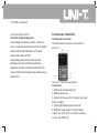
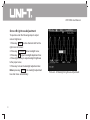
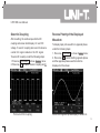
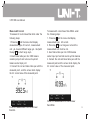
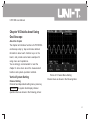
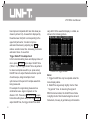
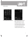
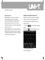
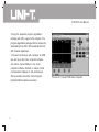
1
L
Series
OPERATING
MANUAL
Preface
Dear users:
Hello! Thanks for you choosing the brand new UNI-T device. In order to use the instrument correctly,
please read the manual thoroughly and especially the Safety Notes part before using the device.
If you have read through the manul, you are recommended to keep the menu properly with the instrument
together or at the place you can read anytime in order to read it in the process of future use.
UTD1000L User Ma nual
Contents
Item
Page
General safety Overview
Preface
ChapterI Safety Information..................................... ....
Chapte II Brief Instroduction of the UTD1025CL Portable Digital Storage
Oscilloscope ......................................................
UTD1025CL Oscilloscope Components ..........................
Features of UTD1025CL Oscilloscope ...........................
Chapter III Oscilloscope Connection.................................
How to Conduct General Check ...............................
Check If Any Damage Resulted By Transportation ..............
Check Accessory ............................................
Check the Complete Apparatus ...............................
Oscilloscope Connection .....................................
Compensation Signal Output Connection of the Apparatus .......
Oscilloscope panels and keys .................................
Chapter IV Primary Application of Oscilloscope .......................
Connect Appatatus to the Electricity Power .....................
Interface Instruction. .........................................
1
4
5
5
6
6
6
6
7
7
8
8
12
12
12
UTD1000L User Ma nual
Item
Page
Reset Oscilloscope ................ .............. ...... 14
Operation Methods for Function Menu........................ 14
Menu Hiding .............................................. 15
Oscilloscope Switch-In Probe Compensation Signal ............. 15
Probe Compensation ............................................ 16
Munual Set Vertical System,Horizontal System and Trigger Level ......... 17
Horizontal System ............................................... 18
Trigger Level ..................................................... 18
Automatic Setting of Waveform Display ..................... 19
Stop/Restore Data Collection ................................. 21
Trigger Frequency Count Setting .............................. 21
Screen Brightness Adjustment. ............................... 22
Store Bitmap .............................................. 23
Online Help ................................................. 23
Set Single Trigger . .......................................... 23
Check Oscilloscope Status ................................... 24
UTD1000L User Ma nual
Item
Page
Check Oscilloscope System Information ... ................. 25
Automatic Parameter Measurement ............................. 25
Customization Parameter Measurement ......................... 26
Smooth Waveform by Average Treatment ........................ 27
Display Spike Pulse by the Peak Value Test Function ............ 28
Use Persistence to Show Waveform ............................. 28
Select AC Coupling .............................................. 29
Reverse Polarity of the Displayed Waveform ..................... 29
Automatic Setting for Small Signal with DC Bias ................. 30
Chapter V Use Multimeter........................................... 32
Connect Apparatus .............................................. 32
Interface Indication Instruction ................................... 32
Multimeter Measurement ........................................ 33
Measure Resistance Value....................................... 33
Measure Diode ............................................34
Continuity Test ............................................ 34
Measure Capacitance ..................................... 35
UTD1000L User Ma nual
Item
Page
Measure DC Voltage ................................... 36
Measure AC Voltage .................................... 36
Measure DC Current ............................................. 37
Measure AC current.............................................. 39
Hold Measurement Value ........................................ 41
Relative Measurement ........................................... 41
Select Automatic/Manual Range Adjustment. ................. 42
Chapter VI Details about Using Oscilloscope............................ 43
Vertical System Setting .......................................... 43
Horizontal Sysmem Setting ...................................... 46
Trigger System Setting........................................... 49
Collection Mode Setting . ......................................57
Display Set.................................................. 58
Parameter Measurement Setting .............................. 60
Storage and Record. ......................................... 65
Record Function............................................. 65
Storage Function.............................................68
UTD1000L User Ma nual
Item
Page
Callback Function ............................................69
Cursor Measurement .........................................71
Interface Set................................................ 73
Auxiliary Function Set ....................................... 74
Mathematic Operation Function ............................... 75
Automatic Set ............................................... 78
Chapter VII Troubleshooting ..................................... 79
Chater VIII Service and Support. ..................................... 81
Product Program Upgradation ................................... 81
Preparations before Upgradation ............................... 81
Program Upgradation Conditions ............................ 81
Program Upgradation ........................................ 81
Chapter IX Appendix ............................................ 84
Appendix A : Performance Index .............................. 84
Appendix B: Maintenance and Cleaning . ...................... 92
UTD1000L User Ma nual
ChapterI Safety Information
Symbols on the product
The following symbols might be on the product:
Safety Terms and Symbol
Terms in the manual
The following terms might be in the manual:
Warning: warning statement indicates the
conditions and activities that might endander life.
Notes: noting statement indicates the conditions and
activities that might cause damage to the product and
other property.
Terms on the product
The following terms might be on the product:
Danger: it means reading the symbol might be
harmful to you immediately.
Warning: it means reading the symbol
Notes: it means damage might be caused to the
product or other property.
High voltage Please pay attention Measurement of
the ground port
to the Manual 1
UTD1000L User Ma nual
General Safety Overview
The apparatus is strictly designed and produced
under the GB4793 Safety Requirements for
Electronic Measuring Apparatus and IEC610101Safety Standard. The apparatus meets the over
voltage standard CATⅢ 600V and safety
standards for pollution level II.
Please read the following safety prevention
measures to prevent personal injury and any
damage to the product or other products connected
with the product. To avoid any possible danger, the
product shall be applicable in the stitulated
scope and be repaired by the specially trained
personnel.
Warning: to prevent electric shocking or fire,
please use the dedicated adapter approved to
apply in the country.
Warning: if the oscilloscope input port were
connected with the voltage higher than 42 V (30
2
Vrms),to avoid electric shocking please:
● To use the voltage probe, test lead wire and
adapter with certain insulation attached with the
oscilloscope or use the accessories designated by
UNI-T applicable to oscilloscope apparatus
series product.
● Before using, check if any mechanic damage to
the multimeter test pen, oscilloscope probe and
accessories and please replace it if any damage
were found.
● To remove all unused test pen, probe an
accessories.
● To insert adapter into the AC socket and connect
it with the oscilloscope.
● In measurement in the CATⅢ ambient,don't
connect the voltage higher than 300V with the
oscilloscope input port and don't connect the
voltage higher than 600V with the multimeter input
port in the CATⅢ ambient.
UTD1000L User Ma nual
In measurement in the CATⅢ ambient,don't
connect the voltage with voltage difference higher
than 300V with the oscilloscope input port and
don't connect the voltage with voltage difference
higher than 600V with the multimeter input port in
the CATⅢ ambient.
● Don't use the input voltage higher than
apparatus rating value
● Use accessories attached with the product and
cease using it if any damage to it.
● Don't plug any metals into the socket.
● Use the oscilloscope with the designated
method.
● The voltage rating value mentioned in the
Warning information is the limit value of adapter
Working Voltage;they represent the Vrms (5060Hz)of AC sine wave in use.
Maintenance shall be conducted only by
qualified techinicians.
●
Pay attention to all terminals'rating value: to
avoid fire or electric shocking,please pay
attention to all rating values and marks.
Don't operate if there is any suspected trouble:
please let the qualified maitainence personnel to
check the product suspected being damaded.
Please don't operate in the moist anbient.
Please don't operate in the explosive anbient.
Keep product suface clean and dry.
3
UTD1000L User Ma nual
Chapte II Brief Instroduction
of the UTD1025CL Portable
Digital Storage Oscilloscope
Brief Instroduction of the UTD1025CL
Portable Digital Storage Oscilloscope
The UTD1025CL series of digital storage
oscilloscope(referred hereinafter as
oscilloscope)are a perfect combination of
usability, uniquie technical index and multipurpose,
helping users completing test more quickly.
The manual concludes the following types:
Sampling
Channel
Bandwidth
Type
velocity
count
UTD1025CL 25MHz
4
200MS/s Single channel
The UTD1025CL series of digital storage
oscilloscope provides a simple and functionally
clear front panel, enabling to conduct all basic
operations,meeting the use habit of traditional
instrument and enabling the user to operate it
proficiently without taking much time to learn and
be familiar with operation of the digital storage
oscilloscope. In order to speed up the adjustment
for measuring, the user can press directly the
button AUTO , and then the instrument shall show
the proper waveform and the gear setting.
Apart from the usability, UTD1025CL series of
digital storage oscilloscope possess high
efficiency index and powerful functions required
for quick measuring. To simplify the menu
operation, the combination operation of key
SHIFT on the apparatus and other keys can
enable direct operation of more functions.
Besides, the powerful trigger and analysis ability
shall make it easier to capture and analyze the
waveform.The clear liquid crystal display and
UTD1000L User Ma nual
mathematical operations help users to observe
and analyze the signal problems more quickly
and clearly.
UTD1025CL Oscilloscope Components
Unpacke the oscilloscope case, you'll see the
following components:
No.
1
Instruction
UNI-T oscilloscope
Standard
configuration
●
2 An adapter
3 An oscilloscope probe
4 2 multimeter test pen(a red and a black)
5 An UT-M07 module
6 An oscilloscope probe adjusting tool
7 A USB data line
8 An user manual
An user disk (inclusive of oscilloscope
9 and comuter communication software)
●
10 A portable soft bag
●
●
●
●
●
●
●
●
Features of UTD1025CL Oscilloscope
Oscilloscope
● Full-automatic setting function (AUTO SCALE)
vertical and time base gear could be
automatically adjusted according to the signal
changes with manual intervention.
● Unique powerful automatic setting function can
make quick and correct automatic setting about
any signal containing DC components.
● Wider voltage measurement scope
20V/div,reach 200V/div in combination with 10×
probe
● USB isolated communication provides safer
USB communication
● Transition from color display to B/W display is
applicable in the strong outdoor light.
● Smart upgradation function user can upgrade
software by local or network.
● Unique waveform recording, storage and
playback function
5
UTD1000L User Ma nual
● Color liquid crystal display with high resolution
and high contrast
● No less than 8 hours of continuous work
● Automatically measure 19 types of waveform
parameters
● Screen printing function
● Help information display both in Chinese and
English
Multimeter
● 3 3/4 bit
● Voltage, current, resistance, diode, capacitance
and conductive measurement
● Current measurement up to 10A
● Extremely low current measurement internal
resistance, precise measurement results
● Mutual isolation between multimeter and
osilloscope
6
Chapter III Oscilloscope
Connection
How to Conduct General Check
Please check the new oscilloscope under the
following steps if you have one:
Check If Any Damage Resulted By
Transportation
If any serious damage of the package carton or
plastic foam protective mat were found, please
contact with the Uni-T distributor or local Uni-T
representative office immediately.
Check Accessory
As regards to the provided accessory details, the
above-mentioned UTD1025CL Oscilloscopes
Accessory in the manual has clearly stated it.You
can check it if there is any damage to the
accessory in reference to the manual.
If any lack or damage of accessories were found,
please contact UNI-T distributor selling the product
UTD1000L User Ma nual
or the local office of UNI-T.
Check the Complete Apparatus
If any damage of accessory surface, or failure to
work or to pass the function test were found, please
contact with the UNI-T distributor or the local
representative office of UNI-T.
If any damage were found, please keep the
package and contact with the transportation
department and the uni-t distributor that sells the
product, UNI-T shall arrange for the maintenance or
replacement.
Oscilloscope Connection
Oscilloscope Connection
The oscilloscope connection is referred to the
picture 3-1
Picture 3-1 Oscilloscope Interface
Instructions:
1. Oscilloscope channel input port
2. USB connection port.
3. Adapter interface used for AC power supply and
battery charging.
4. Probe compensation signal output port
5. Multimeter input socket,3 circular banana
sockets are input ports for voltabe/resistance,
current and COM port.
7
UTD1000L User Ma nual
Compensation Signal Output Connection of the
Apparatus
As shown in the following picture, a
compensation signal (1kHz/3V) output port on the
Left side of the apparatus could be used to adjust
the probe.
Picture 3-2 Compensation Signal Output
Connection of the Apparatus
8
Oscilloscope panels and keys
Panels and keys of oscilloscope are shown in
the picture 3-3:
Picture 3-3 UTD1025CL Panel
UTD1000L User Ma nual
: Power key to power on/off oscilloscope.
F1~F4:Key for menu option setting
: DSO/DMM key:to switch between the
working mode of oscilloscope(DSO) and
multimeter (DMM).
: ACQUIRE/*(brightness)/[V](voltage
measurement) key:under the oscilloscope mode,
press the key to enter ACQUIRE (aquire sample)
menu; Press the key SHIFT firstly and press it
again to adjust brightness and change the
screen brightness by shifting the left/right keys.
Under the multimeter (DMM) mode, press the key
to enter into the voltage measurement menu.
: DISPLAY/CONFIGURE/[I] (current
measurement)key: under the oscilloscope mode,
press the key to enter DISPLAY (display mode)
menu;Press the key SHIFT firstly and press it
again to enter the CONFIGURE (interface
configuration) menu.Under the multimeter
(DMM)mode, press the key to enter into the current
measurement menu.
:MEASURE/CURSOR/[R] (resistance
measurement) key: under the oscilloscope mode,
press the key to enter COURSOR (sursor
measurement) menu;Press the key SHIFT firstly
and press it again to enter the MEASURE
(automatic measurement) menu.Under the
multimeter (DMM) mode, press the key to enter into
the resistance measurement menu and to measure
resistance /diode/ continuity/ capacitance.
:MATH/STATUS key:under oscilloscope
mode, press the key to enter into MATH
(mathematic operation) menu;Press key SHIFT
and press it again,you can open the STATUS
(status bar) display.
: RECORD/STORAGE key: under the
oscilloscope mode, press the key to enter into
RECORD(waveform record) menu;Press key
SHIFT and press it again,you can open the
STORAGE (storage) menu.
9
UTD1000L User Ma nual
: SINGLE/REF key: under the oscilloscope
mode, press the key to set SINGLE(single trigger)
function;Press key SHIFT and press it again,
you can back to the REF(waveform reference)
menu.
: AUTO key:under the oscilloscope mode,
press the key to complete waveform automatic
setting;Press key SHIFT and press it again,you
can open full-automatic setting function,under
which,the oscilloscope shall adjust apparatus
gear automatically with the changes of input signal
and display the waveform in the fittest form
without manual intervention.
RUN/STOP
: RUN/STOP key:under the oscilloscope
mode,press the key to start or stop data collecting;
under the multimeter (DMM) mode, press the key
to hold screen measurement reading.
: UTILITY / TRIGGER key:under the
oscilloscope mode,press the key to enter the
10
TRIGGER(trigger setting)menu;Press key
SHIFT and press it again,you can enter into the
UTILITY (auxiliary function) menu.
: HORIZONTAL / HELP key:under the
oscilloscope mode,press the key to enter the
HORIZONTAL (horizontal setting) menu;Press
key SHIFT and press it again,you can open the
HELP (help) information.
SHIFT : SHIFT key:to select functions in
combination with other function keys.
:Time base:used to change scanning
velocity. Scanning velocity of the apparatus is
50s/div~10ns/div with 1-2-5 system. Press
“S”,the scanning velocity shall slower down a
gear relatively or speeded up.
: Vertical scale: used to change vertical
scale gear. Scale scope of the apparatus is
5mV/div~20V/div with 1-2-5 system. Press
“V”, a vertical scale shall be relatively
increased or reduced.
UTD1000L User Ma nual
Press “V” ,a vertical scale shall be relatively
increased or reduced.
: Selection key: the selection for
switching channel vertical shift and trigger
level shift under normal conditions. If vertical
shift have been selected, the vertical reference
triangle cursor on the screen shall be solid and
you can move vertical position on the screen
of the waveform by adjusting the up/down
keys. If press the key SELECT again, the
vertical triangle cursor of trigger level position
shall be solid and you can change the trigger
position by adjusting the up/down keys.
In the MEASURE menu, the key used to
confirm the selected Customization parameter;
switch cursor 1 and cursor 2 under the cursor
measurement.
: Direction key and OK key:OK key used
to hide/display the present menu bar
under normal circumstances;under the
multimeter (DMM) mode, the keys are used to
confirm the correct connection of 10A CURRENT
DIVIDER in A gear current measurement.
Introduction about the shortcut operation:
SHIFT + OK : Store present display interface into
the storage and outputted from the host computer;
SHIFT + AUTO : open the full-automatic setting
function, under which, the oscilloscope shall adjust
vertical scale and scanning time base automatically
with the changes of input signal and display
the waveform in the fittest form without manual
intervention.
SHIFT + F1 : Open trigger main menu and select
trigger coupling mode and automatic/normal trigger
mode by the key F3/F4 .
11
UTD1000L User Ma nual
Chapter IV Primary Application
of Oscilloscope
Interface Instruction
10
1
9 12 5
11
6
13
4
About the Chapter
The chapter briefly introduces the UTD1025CL
oscilloscope functions,not in detail,providing
some basic examples for using menus and for
basic operations.
7
Connect Appatatus to the Electricity
Power
There are two power supply methods for
UTD1025CL oscilloscope: battery power supply
for home apparatus and adapter power supply,
power supply voltage of which is DC 9V/4A.To
assure the normal working of apparatus, please
use the adapter configurated with the product.
Press power key about 5 seconds, the power-on
LOGO picture shall appear on the oscilloscope
and the oscilloscope starts working.
12
8
2
3
Picture 4-1 Instruction Picture of Display Interface
Apart from the waveform, the display will display
some detailed information about waveform and
oscilloscope control setting.
1. The trigger source status display is as follows:
CH1 represents adjusting the channel waveform
REF represents adjusting the reference waveform
UTD1000L User Ma nual
FFT represents adjusting the FFT operation
waveform
2. Trigger coupling mode display are as follows:
AC trigger coupling mode
DC trigger coupling mode
HF high frequency trigger coupling mode
3. Reading indicates the edge trigger level
position.
4. Trigger status display are as follows:
ARMED oscilloscope is collecting pretrigger data,
under the status all triggers would be neglected;
READY oscilloscope had collected all pretrigger
data and is ready to accept trigger;
TRIG'ED oscilloscope had found a trigger and
is collecting the data after triggered;
STOP oscilloscope ceased collecting waveform
data;
AUTO oscilloscope is under automatic mode and
collecting waveform under the non-trigger status;
SCAN oscilloscope collects and displays
waveform continuously under the scanning
mode.
5. Display time reading of trigger point to the
center scale
6. Symbols indicate power supply modes as
follows:
Battery power supply used by oscilloscope
DC adapter power supply used by oscilloscope
7. Symbols on the screen indicate ground baseline
8. 1×symbol indicates the channel probe
multiplying power is 1
9. Reading displays main time base setting;
10. Home computer connection symbol;
11. Reading displays present vertical scale
coefficient.
12. Waveform opposite phase symbol
13. The reading indicates the shift value of
channel reference symbol relative to screen
horizontal midline.
13
UTD1000L User Ma nual
Reset Oscilloscope
To reset the oscilloscope as factory setting, please
operate under the following steps:
1. Press key SHIFT ,the word“shift”would
appear on the right upper corner of the screen.
2. Press key UTILITY ,select auxiliary function
setting.4 options displayed in the bottom.
3. Press key F2 ,select Default Set.The
oscilloscope shall be set as the factory setting.
Status after factory setting:
Function
Acquire method
s/div
v/div
Trigger coupling
Trigger types
Display format
Continuation time
Interface style
Menu display
Setting
Normal acquire
1ms/div
100mV/div
DC
Automatic
vector
Automatic
Classic
Manual
Operation Methods for Function Menu
Picuture 4-2 Factory Setting
14
The following examples introduce how to select
function with the oscilloscope menu.
1. press function keys on the keyboard, the
relevant set options to keys shall appear on the
bottom of screen, select corresponding function
with keys F1 ~ F4 .after that, press key OK to
hide function menu.
UTD1000L User Manual
2. All keys printed with two lines of words are
multifunctions, for acquiring the above functions,
please press key SHIFT ,the word“shift”shall
appear on the right upper corner of screen and
then press it again to acquire the corresponding
function,
Menu Hiding
Press key OK to hide all key symbols and menu.If
need to display menu or key symbols, press it
again.
Notes: it is possible to set menu automatic hiding
time through interface configuration setting.
Oscilloscope Switch-In Probe
Compensation Signal
Picuture 4-3 Menu Hiding
To switch in signal as the following steps:
1. Connect oscilloscope probe with oscilloscope
input port, and set attenuation multiplying power on
the probe as 10×.
2. Set attenuation coefficient on the probe. It
shall change the vertical gear multiplying power
and the measurement results would reflects
correctly the measured signal's amplitude. Ways
to set the probe attenuation coefficient is: to press
key CHANNEL and press F3 to select probe
multiplying power 10× in the channel.
15
UTD1000L User Ma nual
Picture 4-4 Probe Multiplying Power Adjusting
3. Connect probe with the output port of
compensation signal generator,press key AUTO
and in few seconds,the squarewave display
(1kHz,about 3Vpp,peak peak value)will be seen
as shown in picture 4-5.
16
Picture 4-5 Home Computer Squarewave Signal
Probe Compensation
Connecting probe with channel for the first time,
it is required to adjust probe compensation to
match probe with the input channel.The probe
without compensation calibration shall result in
measurement error or mistakes. To adjust probe
compensation under the steps as shown in the
above example;
UTD1000L User Ma nual
1. Set the attenuation coefficient of probe
multiplying power as 10× firstly, set the switch
on probe as 10×,and connect probe with input
channel of oscilloscope. Connect probe pointer
with output port of the compensation signal
generator.
2. Set automatically;
3. Observe the displayed waveform.
Over compensation correct compensation under
compensation
If the displayed waveform on the screen show
“under compensation”or“over compensation”
as the above picture, use the adjust pen with nonmetal handle of the probe auxiliary to adjust
variable capacitance of the probe until“correct
compensation”were shown on the screen as the
above picture.
Warning: to guard against the electric shock in
measuring the high voltage with the probe, please
make sure that the insulated conductor of probe
is intact and do not touch the metal part of the
probe when connecting with the high voltage
source.
Munual Set Vertical System, Horizontal
System and Trigger Level
Vertical System
Press key V~mV to adjust vertical gear(v/div)
of oscilloscope, and to adjust signal to appear
on the screen with the proper size;
When the channel symbol is solid, press up/down
keys to adjust ground baseline position to adjust
signal to appear on the screen with the proper
size;
17
UTD1000L User Ma nual
way of 1-2-5.
Press left/right key to adjust horizontal positon of
trigger point to observe more pretrigger information.
Picture 4-6 Vertical Shift of Waveform
Notes: press key SELECT to change the function
needed to adjust between channel vertical shift and
trigger level.
Horizontal System
Press key s~ns to change horizontal time base gear
setting, and the time base gear display for status
bar changes correspondingly.The horizontal
scanning velocity is 10ns~50s/div,and step in by the
18
Picture 4-7 Adjust Horizontal Time Base
Trigger Level:
When the trigger level symbol is solid, press up/down
key to adjust trigger level posion.
UTD1000L User Ma nual
Automatic Setting of Waveform Display
Picture 4-8 Adjust Trigger Level
Notes: press key SELECT to change the function
needed to adjust between the channel vertical
shifts and trigger level.The above operations
shall be detailed in the following chapters.
UTD1025CL oscilloscope has the automatic
setting function. Based on the input signal, it is
possible to automatically adjust vertical deflection
coefficient, scanning time base and trigger modes
until the proper waveform display. In application
of automatic setting, frequency of the measured
signal is required to be bigger than or
equivalent to 20Hz,duty ratio bigger than 1﹪.
Full-Automatic Setting of Input Signal
UTD1025CL oscilloscope has the creative
function of full-automatic signal capturing. Under
the function, the oscilloscope shall adjust gear
automatically with the changes of input signal
and display the waveform in the fittest form
without manual intervention.
The following steps shall be taken to operate the
full-automatic setting function:
19
UTD1000L User Ma nual
1. Press key SHIFT to show the character
“shift”on the right upper corner of screen;
2. Press key AUTO to select starting fullautomatic setting function and character A shall
appear on the upper part of screen, indicating
the full-automatic setting function has started;
Picture 4-9 Full-Automatic Setting
Notes:
1. Under the full-automatic setting mode,the
20
“automatic”trigger mode shall not be altered.
2. Entering into the full-automatic setting, the
following setting shall be compulsory:
(1) Under the non-main time base status, it
shall switch to main time base status;
(2) The channel coupling shall switch to AC
coupling, which is unchangeable.
3. To modify vertical scale coefficient of
oscilloscope, horizontal time base, change
vertical and horizontal position of oscilloscope,
the apparatus shall exit full-automatic setting
mode automatically.
UTD1000L User Ma nual
Stop/Restore Data Collection
Trigger Frequency Count Setting
To operate under the following steps to stop data
collection
1. Press key RUN/STOP ,the oscilloscope shall
STOP data collection and trigger status on the
upper part of screen shall display STOP.
2. Press key RUN/STOP to restore data collection
and the oscilloscope shall restart collecting data.
To operate under the following steps to open the
trigger frequency count:
1. Press key SHIFT ,character shift shall appear
on the right corner of screen;
2. Press key UTILITY to show auxiliary function
menu;
3. Press key F3 to select frequency count function
as open;
Picture 4-10 Stop Data Collection
Picture 4-11 Trigger Frequency Count
21
UTD1000L User Ma nual
Screen Brightness Adjustment
To operate under the following steps to adjust
screen brightness:
1. Press key SHIFT to show character shift on the
right corner of screen;
2. Press key ACQUIRE to show backlight menu;
3. Press key F1 to opern backlight adjustment box;
4. Press right/left key to adjust backlight brightness
to the proper value;
5. Press key to close the backlight adjustment box;
Notes: press key AUTO ; the backlight adjustment
box shall close automatically.
22
P icture 4-12 Backlight brightness Adjustment
UTD1000L User Ma nual
Store Bitmap
To store bitmap under the following steps:
1. Press key SHIFT to show character shift on
the right corner of screen;
2. Press key OK to store bitmap into the inner
memory of the apparatus;
Notes: to output bitmap into computer by the home
computer software and to store it in the BMP
format, it is allowed to store 10 groups of bitmap.
Online Help
To conduct online help under the following steps:
1. Press key SHIFT to show character shift on
the right corner of screen;
2. Press key HELP to open help function and
character H shall appear on the upper part of
screen,indicating the help function has started;
3. Press corresponding menu keys to see
detailed help information;
4. Reapeat step 1 and 2 to close help function.
Picture 4-13 Help System
Set Single Trigger
To conduct single trigger setting quickly under the
following steps:
1. Press key SINGLE ,the oscilloscope shall be
set as single trigger mode quickly;
23
UTD1000L User Ma nual
Notes: press key AUTO the status information
shall close automatically.
Picture 4-14 Single Trigger
Check Oscilloscope Status
To conduct online help under the following steps:
1. Press key SHIFT to show character shift on
the right corner of screen;
2. Press key STATUS and the present setting
status of oscilloscope shall appear on the screen;
3. Reapeat step 1 and 2 to close help status
information.
24
Picture 4-15 Status Information
UTD1000L User Ma nual
Check Oscilloscope System Information
To check oscilloscope system information under
the following steps:
1. Press key SHIFT to show character shift on
the right corner of screen;
2. Press key CONFIGURE to open interface
configuration menu;
3. Press key F4 the screen shall display
informations such as: type, versionof the present
oscilloscope.
4. Press key F1 to close system information
window.
Picture 4-16 System Information
Automatic Parameter Measurement
There are two ways of automatic parameter
measurement, showing all parameters or individually
set measured parameter to display on screen with
maximum of 4 parameter items.
Measurement of All Parameters
To measure all parameters automatically under the
following steps:
25
UTD1000L User Ma nual
1. Press key MEASURE to show parameter
measurement menu;
2. Press key F1 the screen shall display
measuremen results of all parameters.
Picture 4-17 Measurement of All Parameters
26
Customization Parameter Measurement
To measure all customization parameters
automatically under the following steps:
1. Press key MEASURE to show customization
parameter menu;
2. Press key F2 ,the screen shall display
measurement parameters for choice.
3. Press key up/down/left/right to select type of
parameter being measured, marked by
complement color;
4. Press key SELECT to confirm, the parameter
shall display on the screen automatically with
set maximum of 4 measuremnt parameters.
5. Press key F2 to close customization
parameter menu.
UTD1000L User Ma nual
3. Press key right/left to select average frequency as
16 and measurement results shall display 16 times in
average.
Picture 4-18Customization Parameters Menu
Smooth Waveform by Average
Treatment
Picture 4-19 Average Treatment with 16 Times
To smooth waveform under the following steps:
1. Press key ACQUIR to show acquisition mode
menu;
2. Press key F1 to select acquisition mode as
average;
27
UTD1000L User Ma nual
Display Spike Pulse by the Peak Value
Test Function
28
Use Persistence to Show Waveform
The function could be used to show results of 50 ns
or even wider (pike pulse or other
nonsynchronous wavefoms)
1. Press key ACQUIR to show acquisition mode
menu;
2. Press key vto select acquisition mode as
peak value .
You can use persistence function to observe
dynamic signal continuously.
1. Press key DISPLAY to show display mode menu;
2. Press key F4 to select 1 second, 3 seconds, 5
seconds, limitless or automatic in a cycle. Select
Limitless,the observed dynamic signal shall
persist on the screen and the persistence function
shall close if select Automatic.
Picture 4-20 Peak Value Acquisition
Picture 4-21 Display 3 Seconds in Consecutive
UTD1000L User Ma nual
Select AC Coupling
After resetting, the oscilloscope shall be DC
coupling and screen shall display AC and DC
voltage.To use AC coupling when want to observe
a small AC signal loaded on the DC signal.
To select AC coupling under the following steps:
1. Press key CHANNEL to show channel menu;
2. Press key F1 to select channel coupling as AC.
Picture 4-22 AC coupling
Reverse Polarity of the Displayed
Waveform
To display input port waveform in opposite phase
under the following steps:
1. Press key CHANNEL to show channel menu;
2. Press key F4 to select starting opposite phase
and the opposite phase waveform shall be
displayed on the screen.
Picture 4-23 opposite phase display of waveform
29
UTD1000L User Ma nual
Automatic Setting for Small Signal with
DC Bias
The unique powerful automatic setting function of
UTD1025CL oscilloscope make it possible to
complete quick, correct automatic setting for
signal containing any DC components under the
channel DC coupling mode.
On the left upper part of screen display a
parameter position.
Position: the parameter indicates the shift value of
channel reference symbol relative to the screen
horizontal midline. Being positive indicates that
channel referenece symbol is above the screen
horizontal midline and negative indicates that
channel referenece symbol is below the screen
horizontal midline.
For example: input in the channel AC peak peak
value70mV with sine signal containing 1.1V DC
bias signal,set oscilloscope to display waveform
30
and read reference value. Compare
UTD1025CL with traditional oscilloscope in
terms of operation convenience.
Connect signal with input channel, set channel
coupling mode as DC, and conduct automatic
setting, then the screen shall display the waveform
shown as in the picture 4-24.
Of which:
Position: -55.0div indicates that the channel
reference symbol shift downward 55div relative
to screen midpoint. Based on the present gear
and shift, we can calculate the DC bias voltage:
20mV/div×55div=1.1V
Peak peak value: 71.199mV represents the AC
peak peak value of the signal and DC level of
present signal could be read directrly by the
average value.
Average value: 1.120V represents the DC level of
the signal and the signal's parameter could be
calculated easily based on the above parameters.
UTD1000L User Ma nual
Picture 4-24 Setting the Signal with DC Bias
For trational oscilloscope, it is necessary to set it
as AC coupling and measure signal's AC
parameter; set channel as DC, manually adjust
channel vertical scale coefficient and measure
signal's DC parameter by the cursor, and get the
test value finally, as shown in following picture.
Picture 4-25 AC parameter measurement
31
UTD1000L User Ma nual
ChapterV Use Multimeter
About the Chapter
The chapter introduces the multimeter function of
oscilloscope in phases and provides basic
examples for using menu and basic operations.
Press key DMM/DSO ,the oscilloscope shall
switch to multimeter measurement and screen
displays multimeter interface.
Connect Apparatus
Picture 4-26 DC parameter measurement
After comparison,we can see UTD1025CL's
quicker measurement speed and more intuitive
measurement results.
32
3 4-mm safety banana socket input ports for
multimeter: COM、V/Ω、μA/mA
One 10A CURRENT DIVIDER: UT-M07.
Interface Indication Instruction
Instructions:
1.
Battery indication
2. AUTO automatic setting indication
3. Measurement types indication:
DC voltage measurement
UTD1000L User Ma nual
AC voltage measurement
DC current measurement
AC current measurement
Resistance measurement
Diode measurement
Continuity measurement
Capacitance measurement
4.
Relative value measurement indications
5. Operation status indication: HOLD indicates
the screen has been hold.
6.
Relative value measures reference value.
7.
Measurement value main reading.
Measure Resistance Value
To measure resistance under the following steps:
1. Press key R ,the menu shall display the
measurement type:resistance.
2. Insert blace table pen into COM banana socket
input port and red one into Ω banana socket input
port.
3. Connect the red and blace table pen with the
measured resistor,the screen shall display
resistance value reading of the measured
resistor.
Multimeter Measurement
Press key DMM/DSO ,the oscilloscope shall
switch to multimeter measurement and screen
displays multimeter interface, then you can
measure with the multimeter.
Picture 5-1 Resistance Measurement
33
UTD1000L User Ma nual
Measure Diode
To measure diode under the following steps:
1. Press key R ,the menu shall display the
measurement type: resistance.
2. Press key F1 ,the menu shall display the
measurement type: diode.
3. Insert blace table pen into COM banana
socket input port and red one into Ω banana
socket input port.
4. Connect the red and blace table pen with the
measured resistor,the screen shall display the
turn-on voltage drop voltage value reading of the
diode.
34
Picture 5-2 Diode Measurement
Continuity Test
To conduct continuity test under the following
steps:
1. Press key R ,the menu shall display the
measurement type:resistance.
2. Press key F1 ,the menu shall display the
measurement type: continuity.
3. Insert blace table pen into COM banana socket
input port and red one into Ω banana socket input
port.
UTD1000L User Ma nual
4. Connect the red and blace table pen with the
measured point,when the measured point
resistance is lower than 10 Ω, the meter shall
sound “tick…”
input port and red one into Ω banana socket input
port.
4. Connect the red and blace table pen with the
capacitor being measured; the screen shall
display capacitance value reading of the
capacitor being measured.
Notes: please use the relative value measurement
method in measuring capacitance lower than 5 nF
and to improve measurement accuracy.
Picture 5-3 Continuity Measurement
Measure Capacitance
To measure capacitance under the following steps:
1. Press key R ,the menu shall display the
measurement type: resistance.
2. Press key F1 ,the menu shall display the
measurement type: continuity.
3. Insert blace table pen into COM banana socket
Picuture 5-4 Continuity Measurement
35
UTD1000L User Ma nual
Measure DC Voltage
To measure DC voltage under the following steps:
1. Press key V ,the menu shall display the
measurement type: DC Voltage.
2. Insert blace table pen into COM banana
socket input port and red one into V banana
socket input port.
3. Connect the red and blace table pen with the
measured point,and the screen shall display the
DC voltage value of the measured point as
shown in the following picture:
Picture 5-5 DC Voltage Measurement
36
Measure AC Voltage
To measure AC voltage under the following steps:
1. Press key V ,the menu shall display the
measurement type: DC Voltage.
2. Press key F1 ,the menu shall display the
measurement type:AC voltage.
3. Insert blace table pen into COM banana
socket input port and red one into V banana
socket input port.
4. Connect the red and blace table pen with the
measured point,and the screen shall display the
AC voltage value of the measured point
Picture 5-6 AC Voltage Measurement
UTD1000L User Ma nual
Measure DC Current
To measure DC current lower than 4mA under the
following steps:
1. Press key I and the menu shall display
measurement type: DC current, measurement unit:
μA. to select different range (μA、mA、A) with the
key F3 ,the fault range is mA .
2. Insert blace table pen into COM banana
socket input port and red one into μA/mA
banana socket input port.
3. Connect the red and blace table pen with the
measured point,and the screen shall display the
DC current value of the measured point.
Picture 5-7 Measurement of DC Current Lower
Than 4mA
To measure DC current lower than 400mA under
the following steps:
1. Press key I and the menu shall display
measurement type:DC current.
2. Press key F3 to set range as mA, and the
measurement unit shall be mA.
3. Insert blace table pen into COM banana socket
input port and red one into μA /mA banana socket
input port.
37
UTD1000L User Ma nual
4. Connect the red and blace table pen with the
measured point,and the screen shall display the
DC current value of the measured point
measurement socket and then insert the table
pen with the 10A CURRENT DIVIDER.
4. Connect the red and blace table pen with the
measured point, and the screen shall display the
DC current value of the measured point
Warning: in measuring current higher than
400mA, the fuse in the machine shall be
blown if plug in μA /mA port directly without
using 10A CURRENT DIVIDER,please replace
the fuse by the special personnel.
Picture 5-8 Measurement of DC Current Lower Than
400mA
To measure DC current higher than 400mA under
the following steps:
1. Press key I and the menu shall display
measurement type: DC current.
2. Press key F3 to set range as A, and the
measurement unit shall be A.
3. Insert 10A CURRENT DIVIDER into current
38
Picture 5-9 Measurement of DC Current Higher
Than 400mA
UTD1000L User Ma nual
Measure AC Current
To measure AC current lower than 4mA under the
following steps:
1. Press key I and the menu shall display
measurement type:AC current, measurement
unit: μA. to select different range (μA、mA A)with
the key F3 ,the fault range is μA.
2. Insert blace table pen into COM banana
socket input port and red one into μA /mA
banana socket input port.
3. Connect the red and blace table pen with the
measured point, and the screen shall display
the AC current value of the measured point.
To measure AC current lower than 400mA under
the following steps:
1. Press key I and the menu shall display
measurement type: AC current.
2. Press key F3 to set range as mA and the
measurement unit shall be mA.
3. Insert blace table pen into COM banana
socket input port and red one into μA /mA banana
4. Connect the red and blace table pen with the
measured point,and the screen shall display the
AC current value of the measured point.
Picture 5-11 Measurement of AC Current lower
than 400mA
Picture 5-10 Measurement of AC Current lower
than 4mA
39
UTD1000L User Ma nual
To measure AC current higher than 400mA under
the following steps:
1. Press key I and the menu shall display
measurement type: AC current.
2. Press key F3 to set range as A, and the
measurement unit shall be A.
3. Insert 10A CURRENT DIVIDER into current
measurement socket and then insert the table
pen with the 10A CURRENT DIVIDER.
4. Connect the red and blace table pen with the
measured point, and the screen shall display
the AC current value of the measured point.
Warning: in measuring current higher than
400mA, the fuse in the machine shall be
blown if plug in μA /mA port directly without
using 10A CURRENT DIVIDER, please replace
the fuse by the special personnel.
40
Picture 5-12 Measurement of AC Current higher than
400mA
UTD1000L User Ma nual
Hold Measurement Value
Relative Measurement
You can hold the displayed reading antime.
Relative measurement shall display the present
measurement results relative to the difined
reference value.
The following example introduces how to conduct
relative capacitance measurement. Firstly, to get
a reference value:
1. Press key R and the menu shall display
measurement type: resistance.
2. Press key F1 , the screen shall display
measurement type: capacitance.
3. Insert blace table pen into COM banana
socket input port and red one into V/Ω banana
socket input port.
4. When the reading is stable, press key F2 to
enter into relative value measurement status and
the △ shall appear on the upper part of screen ,
under △ the appear reference value.
1. Press key RUN /STOP to hold the
measurement value and character Hold shall
flicker on the screen.
2. Press the key RUN /STOP again to restore
measurement.
Picuture 5-13 Hold Measurement Value
41
UTD1000L User Ma nual
5. Connect the red and blace table pen with the
capacitor being measured,and the screen shall
display the capacitance reading of capacitor being
measurend.
2. Press key F2 to switch measurement mode,
and enter into manual measurement mode, menu
display range mode: manual.
3. Under manual range mode,press key F3
once,jump a gear upward and press key F3 to the
lowest gear when it reaches to the highest gear in a
cycle. The present range displays above the
measurement reading.
4. Press key F2 ,the left upper part of screen
displays Auto,and switch back to full-automatic
setting mode.
Picture 5-14 Relative Measurement of Capacitance
Select Automatic/Manual Range Adjustment
The fault mode of meter is full-automatic setting
mode, to switch to manual range under the
following steps:
1. Press key V or R ,menu display measurement
mode: automatic.
Picture 5-15 Manual Measurement
42
UTD1000L User Ma nual
Chapter VI Details about Using
Oscilloscope
About the Chapter
The chapter will introduce functions of UTD1025CL
oscilloscope step by step and make detailed
introduction about each function keys on the
board, and provide some basic examples for
using menu and operations.
You are strongly recommended to read the
chapter to know more about the measurement
function and system operation methods.
Vertical System Setting
Channel Setting
Channel has independent setting menu, press key
CHANNEL ,the system shall display channel
operation menu as shown in the following picture:
Picture 6-1 Channel Menu Setting
Channel menu as shown in the following table:
43
UTD1000L User Ma nual
Table 6-1
Coupling
Waverform
display
Probe
lnvert
44
DC
AC
Ground
Pass AC and DC components of the input signal.
Stop the DC components of the input signal.
Display DC level of the channel input port being equivalently grounded.
On
Off
1×
10×
100×
1000×
Display channel waveform;
Close channel waveform.
Off
On
Based on the probe attenuation coefficient, select one of them to assure
the accuracy of the vertical bias coefficient reading.
Four types: 1×、10×、100×、1000×.
Normal Waveform display
Waveform being displayed in the opposite phase mode.
UTD1000L User Ma nual
Vertical Shift of the Waveform
When the channel triangle symbol is solid,
press up/down key to shift channel waveform
vertically.
Picture 6-2 Vertical Shift of Waveform
Notes: when the channel vertical shift triangle
symbol is blank, press key SELECT to switch
channel vertical shift triangle symbol to solid.
Set Waveform Display
In the channel menu, press key F2 to open or close
channel waveform display.
Picture 6-3 Close Waveform Display
Set Probe Multiplying Power
To cooperate with the probe attenuation coefficient
setting, it is required to set probe attenuation
coefficient correspondingly in the channel
operation menu. For example: the probe
attenuation coefficient is 10:1,the probe coefficient
in menu shall be correspondingly set as 10
×,others are on the analogy of the above to
assure accuracy of voltage reading.
45
UTD1000L User Ma nual
In the channel menu, press key F3 to set probe
multiplying power.
Table for probe attenuation coefficient and
corresponding menu settng
Table 6-2
Probe attenuation
coefficient
1:1
10:1
100:1
1000:1
Corresponding menu
1×
1 0×
100×
1000×
Horizontal Sysmem Setting
Change of Time Base
Press key s~ns to slow down or speed up
scanning velocity of the apparatus from 10ns/div
to 50s/div.
Notes: minimum time base gear shall vary with
types.
46
Horizontal Shift of Waveform
Press key left/right to adjust pretrigger depth. The
trigger position generally is set at the screen
horizontal center and you can see the 6 div
pretrigger and delay information. Through
adjusting waveform horizontal position, you can
see more pretrigger information and based on
the observed pretrigger data to see the
waveform status prior to trigger.For example:if
capture the glitch produced during the circuit
start time,to find the reason by observing and
analizing pretrigger data.
Press key HORIZONTAL to open horizontal
setting menu as shown in the following picture
UTD1000L User Ma nual
Picture 6-4 Horizontal Setting Menu
There are two function options in the horizontal
setting menu: window extension and trigger
holdoff.
Window Extension Function
In the horizontal setting menu, press key F1 to
open window extension function to amplify a sector
of waveform, checking the picture details. Window
extension setting shall not be slower than the main
time base setting.
Picture 6-5 Screen Display after Window Extension
Two display sector in the window extension
function,as shown in the above picture.The upper
part displays the original waveform,after pressing
the key OK to hide menu,the sector could be
used to shift horizontal extension part left/right by
adjusting right/left key and increase or reduce the
selection area by the key s~ns .
The lower half part is the waveform after horizontal
extension of the selected original sector. It is
noteworthy that resolution of the extension time base
47
UTD1000L User Ma nual
has improved compared with main time base (as
shown in picture 6-5). As waveform displayed by
the whole lower half part is corresponding to the
upper half part sector, it is able to improve
extension time base by adjusting key s~ns to
reduce selected area,thus increasing horizontal
extension times of waveform.
Trigger Holdoff Time Adjustment
In the horizontal setting menu and display status of
menu,press left/right key to adjust holdoff time
(100ns-1.5s).Use trigger holdoff time adjustment
to observe complet waveform (ex. pulse serial).
Holdoff time is to adjust the data collection period
of oscilloscope, integral multiple of and
sychoronous to the period of complex waveform
being measured.
For example: the signal being measured is a
combination wave signal imposed on the
channel CH1.Press key HORIZONTAL to open
horizontal setting menu and press key left/right to
adjust holdoff time, the trigger holdoff time shall
48
vary with it till the waveform display is stable,as
shown in the following picture.
Picture 6-6 Trigger Holdoff
Notes:
1. Trigger holdoff time only be adjusted under the
menu display status.
2. Holdoff time is generally slightly shorter than
“big period”time.In observing the signal of
RS232 communication, the holdoff time is frame
is slightly shorter than the start edge time of each
frame data, it is easy to get stable synchronization.
UTD1000L User Ma nual
Trigger System Setting
Trigger decides when to start collecting data and
displaying waveform for oscilloscope. If trigger
has been set correctly, it shall transform the
unstable display into meaningful waveform. In
collecting data, the oscilloscope shall collect
enough data to draw wavefrom on the left of trigger
point. In waiting for the occurrence of trigger
conditions,it shall collect enough data
countinously to draw wavefrom on the right of
trigger point.The trigger function of oscilloscope
could be set by the trigger function key TRIGGER .
TRIGGER:Key for trigger function setting menu
Trigger level: used to set the signal voltage relative
to trigger point.
Press key TRIGGER to open trigger menu as
shown in the following picture and press key F1
to switch trigger types.
Picture 6-7 Trigger Function Menus
Trigger control
Four trigger modes: edge, vedio, pluse width and
slope, different function menu for each trigger
and a general setting mode used to set trigger
source, trigger coupling and trigger modes.
Edge trigger: produce trigger when signal is set as
rising or falling edge. To change vertical positon of
trigger point on the trigger edge by setting trigger
level, namely the intersection point of trigger level
line and signal edge on the interface.
49
UTD1000L User Ma nual
Pulse width trigger: trigger will occur when the
pulse width of trigger signal reaches set conditions.
Vedio trigger: to trigger in the vertical or horizontal
signal of standard vedio signal
Slope trigger: signal's rising or falling velocity is
the trigger condition
Sorts of trigger menu shall be introduced in the
following contents.
Common Trigger Setting
The Common setting is used to set common trigger
options as shown in the following table:
50
Picture 6-8 Trigger-Common Setting
Table 6-3
Instruction
Set general trigger
Trigger Type Common set
options
Set CH1 as information
Trigger source CH1
source trigger signal
Stop DC components
AC
contained in the input
signal
Pass AC and DC
DC
components in the input
Trigger coupling
signal;
High frequency Resitrict high frequency
components higher than
restriction
80kHz in the signal
Automatically collect
Automatic
waveform if without
detecting any trigger
Trigger modes
conditions
Collect waveform only
Normal
trigger conditions have
been met
Function menu
Set
UTD1000L User Ma nual
Notes:
General setting menu can also set by shortcut
ways, as shown in the following steps:
1. Press key SHIFT and character shift shall
appear on the right upper corner of screen;
2. Press key F1 to show trigger general setting
menu;
Edge Trigger
Edge trigger is the trigger on the trigger threshold
of input signal edge. Edge trigger setting are as
shown in the following table.
Table 6-4
Function menu
Set
Trigger Type
Edge
Rise
Slope
Fall
Instruction
Set trigger type as edge
trigger.
Set trigger on the signal
rising edge;
Set trigger on the signal
falling edge.
Pulse Width Trigger
Pulse width trigge defines trigger time based on the
pulse width. You can capture abnormal pulse by
setting pulse width conditions.
Picture 6-9 Trigger-Edge Trigger
Picturen 6-10 Trigger-Pulse Width Trigger
51
UTD1000L User Ma nual
Table 6-5
Function menu
Trigger Type
Pulse width
polarity
Instruction
Set trigger type as edge
Pluse width
trigger.
Set positive pulse width
Positive
as the trigger signal
Negative
Set negative pulse width
as the trigger signal
Set
=
Pulse width
conditions
﹤
﹥
Pulse width time
52
---
Trigger when pulse width
equals to setting value;
Trigger when pulse width
is bigger than setting value;
Trigger when pulse width
is smaller than setting value.
Set pulse width time value ,
under the menu display
conditions, set the pulse
width time by left/right key.
Vedio Trigger
Select vedio trigger and trigger on the vertical or
horizontal line of NTC or PAL standard vedio
signal.
Picture 6-11 Trigger-Vedio Triger
UTD1000L User Ma nual
Tabel 6-6
Function menu
Trigger Type
Standard
Sync
Set
Vedio
PAL
NTSC
All lines
Odd field
Even field
Instruction
Set trigger type as vedio trigger
Vedio signal applicable to PAL system
Vedio signal applicable to NTSC system.
Set vedio horizontal trigger sync
Set to trigger sync on the vedio odd field
Set to trigger sync on the vedio even field
53
UTD1000L User Ma nual
Slope Trigger
Select slope trigger, and produce trigger when
signal rising or falling velocity meets set value
conditions.
Picture 6-13 the Second Page of Trigger-Slope
Trigger
Picture 6-12 the First Page of Trigger-Slope
Trigger
54
UTD1000L User Ma nual
Tabel 6-7
Function menu
Trigger Type
Slope
Set
Slope
Rise
Fall
﹥
﹤
Slope conditions
=
Next page
----
Time
----
Threshold
Back
Low level
High level
High/low level
----
Instruction
Set trigger type as slope trigger.
Select a threshold between the rising edge of trigger signal
Select a threshold between the falling edge of trigger signal
Trigger when signal slope between thresholds is bigger than slew
rate set value
Trigger when signal slope between thresholds is smaller than slew
rate set value
Trigger when signal slope between thresholds equals to slew rate
set value
Second page of slope menu
Set slew rate value and under the menu display conditions to set
pulse width time by left/right key.
Shift low level threshold by up/down key
Shift high level threshold by up/down key
Shift high/low level threshold by up/down key
Back to the first page of slope page
55
UTD1000L User Ma nual
Terms explanation
1. Trigger Source: trigger information source is
the input channel CH1.
■ Input Channel: the commonly used channel
information source is input channel (CH1). The
channel selected as trigger information source
are under normal operation only its.
corresponding input channel have been opened.
2. Trigger Mode: decides activity modes of
oscilloscope under no trigger event status. Three
trigger modes: automatic, normal and single
trigger.
■ Automatic trigger: when no trigger signal input
status, the system shall collect waveform data
automatically, enabling to display scan baseline
on the screen; when there is trigger signal, the
automatic shall switch to trigger scanning and sync
with signal.
Notes: when scan waveform is set at the 50ms/div
56
or slower time base, oscilloscope shall enter
into SCAN mode.
■ Normal trigger: oscilloscope shall collect
waveform under normal trigger mode only
trigger conditions have been met. When there is
no trigger signal, it stops collecting data and awaits
trigger. While there is trigger signal, it shall
produce trigger scan.
■ Single trigger: under the single trigger mode,
press “operation”key once,oscilloscope shall
await trigger and when detecting a trigger, it
shall collect and display the collected waveforms,
then stop it.
3. Trigger coupling: it decides which
components of signal will be transmitted to trigger
circuit. Coupling types include: DC, AC and high
frequency restriction.
■ DC: pass all components of signal.
UTD1000L User Ma nual
■ AC: stop “DC”component and attenuate
signal lower than 10HZ.
■ High frequency restriction: attenuate high
frequency components over 80kHz.
4. pretrigger/delay trigger: data collected
before/after trigger event.Generally, trigger is set
at the horizontal center of screen;you can observe
6div pretrigger and delay information. You can
adjust horizontal position of waveform to see more
pretrigger information, by observing pretrigger
data to see waveform before trigger.For
example: if capturing glitch when the circuit is
power on, we can find the reason of occurrence of
glitch by observing and analyzing pretrigger
data.
Collection Mode Setting
Press key ACQUIRE to enter into collection mode
menu,as shown in the following table:
Table 6-8
Function menu
Instruction
Set as common
acquisition mode
Peak value Set as peak value test
mode
Set as average acquisition
Average
mode and display average
frequency
Set average frequency and
step in with multiple of 2,
from 2,4,and 8,16,32,64
128 to 256.
2~256
Under collection menu
display status,set average
frequency by left/right key.
Set
Normal
Acquisition
Averages
(appear only
the acquisition
mode is
average)
57
UTD1000L User Ma nual
Notes:
1. Select acquisition mode to observe single
signal.
2. Select peak value test mode to observe
envelop of signal to avoid confusion.
3. Select average acquisition mode to reduce
random noise in the displayed signal and the
average value frequency shall step in with
multiples of 2, setting average frequency
selection from 2 to 256.
Nouns explanation
Normal mode: oscilloscope collects signal to
reconstruct waveform with equal time interval.
Peak value test mode: under the acquisition
mode, oscilloscope shall find out the maximum
and minimum value of input signal in each
acquisition intervals and to display waveform by
those values. Thus, oscilloscope can acquire
and display narrow pulse or those narrow pulses
will be leaked under the “acquisition”mode and
58
noise seems louder.
Average mode: under the mode, oscilloscope will
acquire several waveforms to calculate average
value and display waveform finally, thus,
reducing random noise.
Display Set
Press key DISPLAY to enter into display menu, as
shown in the following picture:
Picture 6-14 Waveform Display Set
UTD1000L User Ma nual
Table 6-9
Function menu
Format
Types
Graticule
Persist
Set
YT
Vectors
points
Full
Grid
Cross Hairs
Automatic
1s
3s
5s
lnfinite
Instruction
Indicate relative relations between vertical voltage and horizontal time.
Display in the way of linking acquisition points
Display acquisition points directly
Set mesh display mode in the waveform display area : full ,
grid , crosshairs.
Screen waveform updates at normal refresh rate;
Waveform data on screen updates after holding 1 s.
Waveform data on screen updates after holding 3 s.
Waveform data on screen updates after holding 5s.
Wavefrom data on screen shall hold continuously and new data,
if any, shall display in continuity .
59
UTD1000L User Ma nual
Nouns explanation:
Display types: sector display will fill in blanks
between adjacent acquisition points during
display, and point display shall only display
acquisition point.
Refresh rate: it is the refresh frequency per
seconds of screen waveforms. Speed of refresh
rate will affect oscilloscope's ability to observe
signal dynamic changes.
Y-T mode: Y axis represents voltage quantity and
X axis time quantity.
Slow scan mode: when horizontal time base
control is set at 50ms/div or slower, the
apparatus shall enter into slow scan acquisition
mode. It is recommended to set channel
coupling as DC in using slow scan mode
toobserve low frequency signal.
60
Parameter Measurement Setting
The following introduction shall help you to know
more about the powerful automatic
measurement function of oscilloscope. Press
key MEASURE to open parameter measurement
menu, as shown in the following picture:
Picture 6-15 Parameter Measurement Menu
UTD1000L User Ma nual
T able 6-10
Function menu
All parameters
Set
ON
OFF
ON
Select
paramter
Open customization
parameter selection box
to select the needed
measured parameter by
key SELECT .
The parameter will appear
Example 1: display all measurement values of
channel. Measurement steps are as follows:
1. Press key MEASURE to open parameter
measurement menu;
2. Press F1 to select all parameter measurement:
open
Screen will display all measurement parameters, as
shown in the following picture:
on screen and you can
select at most four
OFF
Clear
Instruction
Display measurement
value of all parameters
Close automatic
measurement function
---
customization parameters.
Close customization
parameter selection box
Delete customization
parameter displayed on
screen
Picture 6-16 All Parameters Measurement
61
UTD1000L User Ma nual
Example 2: to display channel peak peak value,
amplitude under the following steps:
1. Press key MEASURE to open parameter
measurement menu;
2. Press key F2 to open customization parameter
selection box;
3. Press up/down /left/right key to select peak
peak value parameter;
4. Select peak peak value parameter and to
press key SELECT to confirm; a dot shall
appear before the peak peak value in the
customization parameter selection box,
indicating the parameter has been customized
and will appear on screen concurrently.
5. Same to the above operation press
up/down/left/right key to select amplitude
parameter;
6. Press key SELECT to confirm, a dot shall
appear before the amplitude paramters,
62
indicating the parameter has been customized
successfully and will appear on screen
concurrently.
7. Press F2 to close customization parameter
selection box;
Then, “peak peak value” and “amplitude”
parameter shall appear on the right upper part
of screen, as shown in the following picture:
Picture 6-17 Peak Peak Value Parameter
Customizations
UTD1000L User Ma nual
Picture 6-18 Amplitude Parameter Customizations
Picture 6-19Amplitude Parameter Customizations
Notes: Designated parameters are used for
quick parameter measurement. There are 19
types of measurement parameters and generally
user just need to measure some of them and set
as customization parameter instead of all. All
customization parameters shall appear on screen.
63
UTD1000L User Ma nual
Automatic measurement of parameter
Picture 6-20 Voltage Parameter Measurement
Voltage parameters that oscilloscope can
automatically measure include:
Maximum value (Vmax):Voltage value from
waveform highest point to GND (ground)
Minimum value (Vmin): Voltage value from
waveform lowest point to GND (ground)
Top value (Vtop): Voltage value from waveform top
to GND (ground)
64
Base value (Vbase): voltage value from waveform
base to GND (ground)
Middle value (Vmid): half of amplitude value
Peak peak value (Vpp): voltage value from
waveform highest point to the lowest point
Amplitude value (Vamp): voltage value from
waveform top to bottom
Overshoot: ratio of difference between waveform
maximum value and top value with amplitude value
Preshoot: ratio of difference between waveform
minimum value and bottom value with amplitude
Average value: average amplitude of signal during
a period
Root-mean-square value: the valid value. It means
the converted energy of AC signal in a period is
corresponding to the DC voltage that produces
equivalent energy.
UTD1000L User Ma nual
pulse is at 50% amplitude
Rise delay: delay time of A to B rise edge
Fall delay: delay time of A to B fall edge
Positive duty ratio: ratio of positive pulse width with
period
Negative duty ratio:ratio of negative pulse width
with period
Storage and Record
Picture 6-21 Time Parameter Measurement
The time parameters that oscilloscope can
measure automatically include:
Rise time: duration for waveform rising from 10%
to 90%
Fall time: duration for waveformfalling from 90%
to10%
Positive pulse width: pulse width when positive
pulse is at 50% amplitude
Negative pulse width: pulse width when negative
Record Function
Press key RECORD to open waveform record
function menu, two independent menus as shown
in the following picture:
65
UTD1000L User Ma nual
Picture 6-22 Waveform Record Menu
Table 6-11 Record Menu
Instruction
Set
Function menu
Open/close waveform
Rec Op...
Record
record function
Play
Play
recorded waveform
---files
Stop
Stop the waveform files
---being recorded or played
Rec
Record waveform
---66
Picture 6-23 record file storage menu
UTD1000L User Ma nual
Table 6-12 record file storage menu
Instruction
Set
Function menu
Rec Op...
Location
Savec
1-5
Open/close waveform
recording function
5 storage positions“1-5”
Set storage position by
left/right key under the
menu display condition
Save
----
Save recorded files into
inner memory of the
machine
Load
----
Callbacke recorded files
saved into inner memory
and playback it.
Notes: recorded files saved into the machine could
be output to computer by host computer and played
in it.
For example: it is required to record waveform of
channel and save the file into inner memory.
1. Press key RECORD to enter into waveform
recording menu;
2. Press key F1 to select menu function as record;
3. Press key F4 to start recording and press key
F3 to stop;
4. Press key F1 to select menu function as
store;
5. Press left/right key to adjust address as 1;
6. Press key F3 to store recorded waveform and
screen shall display saving…, await saving…
indicator to disappear, the waveform shall be
stored into inner memory of the machnine.
Notes: oscilloscope can record at most 300
screens of waveform data and during recording,if
the following operations are conducted the
record shall stop.
■ Change horizontal position of signal(under stop
status)
67
UTD1000L User Ma nual
For example: it is required to callbacke waveform
recorded file that saved into inner memory in the
example 1 to oscilloscope and playback.
1. Press key RECORD to enter into waveform
record menu;
2. Press key F1 to select menu function as store;
3. Press left/right key to adjust address as 1;
4. Press key F4 to select callback; screen will
display loading…, after successful callback,
indicating Load Success;
5. Press key F1 again to select menu function as
record;
6. Press key F2 to play automatically the
callbacked waveform and press key F3 to stop it, to
manual play with left/right key.
68
Picture 6-24 Recorded waveform playback
Storage Function
To store wavefom under the following steps:
1. Press key SHIFT and character shift will
appear on the right upper corner of screen.
2. Press key STORAGE to enter into waveform
storage setting menu.
UTD1000L User Ma nual
In the storage memu, set as follows:
Table 6-13
Instruction
Function menu Set
Setting
Store sets in oscilloscope
present menus;
Type
wave
Store waveform of channel.
Picture 6-25 Set storage menu
Location
1-20
Save
----
Load
(appear below
set menu)
1-20
Select storage position
with left/right key.
Save as the former selected
operationswith left/right key.
Callback saved apparatus
configuration parameters
in the set menu.
Callback Function
ress key REF to enter into reference waveform
callback set menu for waveform callback.
Picture 6-26 Waveform storage menu
69
UTD1000L User Ma nual
Picture 6-27 Reference Waveform Callback
Set as shown in the following table:
Table 6-14
Instruction
Function menu Set
Ref Wave
REF A
Select callback route
Location
1-20
Load
----
Close
----
Select callback position
with the right/left key
mplement the former
selected operations
Close and callback to
reference waveform on
screen
70
For example: it is required to save channel
waveform into oscilloscope and callback.
Waveform storage
1. Press key SHIFT and character shift will
appear on the right upper corner of screen;
2. Press key STORAGE to enter into waveform
storage setting menu;
3. Press key F1 to select storage type as
waveform;
4. Press left/right key to select storage position
as 1;
5. Press key F3 to save, storage success indicated
on screen means save successful and waveform
shall be stored into oscilloscope;
Waveform callback
6. Press key SHIFT and character shift will
appear on the right upper corner of screen;
7. Press key REF to enter into reference
waveform callback set menu
UTD1000L User Ma nual
8. Press left/right key to select storage position
as 1;
9. Press key F3 to callback, Load Success
indicated on screen means callback successful and
waveform shall appear on screen;
10. Press key F4 to close reference waveform.
Cursor Measurement
To callback waveform under the following steps:
1. Press key SHIFT and character shift will
appear on the right upper corner of screen;
2. Press key to enter into cursor set menu;
3. Press key F3 to select cursor measurement
type;
There are two cursor measurement types in cursor
measurement menu: voltage and time.
In measuring voltage, you can use key SELECT
on board and up/down/left/right key to adjust
cursor position respectively,it means to
measure ΔV,if select time ,you can measure Δt.
Voltage/time measurement method: when cursor
1or 2 appear at the same time,adjust cursor
position with the up/down/left/right key and
press key SELECT to select cursor. Reading
displayed shall be voltage or time value between
the two cursors.
If cursor function is open, measurement value shall
appear automatically on the left upper corner of
screen.
Picture 6-28 Time Cursor Measurement Menu
71
UTD1000L User Ma nual
Table 6-15
Function menu
Set
Instruction
Cursor used to measure
time
Independent To shift any one of two
cursors independently
Modes
Tracking
To shift two cursors
concurrently,maintaining Δt
Measurement parameter is
Second
time
Cursor Units
Hz
Measurement parameter is
frequency
To select shift target as
Channel
channel waveform ;
Trigger
To select shift target as
trigger level ;
Function switch
Cursor
To select shift target as
measuring cursor ,and
press key SELECT to
switch cursor 1 and 2.
Types
72
Time
Picture 6-29 Voltage Cursor Measurement Menu
UTD1000L User Ma nual
Table 6-16
Function menu
Set
Instruction
Amplitude Cursor used to measure
voltage
Independent To shift any one of two
cursors independently
Modes
Tracking
To shift two cursors
concurrently,maintaining Δt
To select shift target as
Channel
channel waveform ;
To select shift target as
Trigger
trigger level ;
Function switch
To select shift target as
Cursor
measuring cursor ,and
press key SELECT to
switch cursor 1 and 2.
Types
Interface Set
To set oscilloscope display interface under the
following steps:
1. Press key SHIFT and character shift will
appear on the right upper corner of screen;
2. Press key CONFIGURE to enter into interface
set menu.
73
UTD1000L User Ma nual
Table 6-17
Function menu
Auxiliary Function Set
Set
Chinese
Language
English
Skin
Menu display
Version
74
Instruction
Select menu language
types
Classic,
traditional,
modern and Select display style
black white
Set awaited close time for
menu box:5s、10s、20s
and manul;The last one
---can not close automatically
and need to press key OK
to close or open.
Display informations such
as oscilloscope types,
---hardware version,software
version etc.
To set oscilloscope display interface under the
following steps:
1. Press key SHIFT and character shift will
appear on the right upper corner of screen;
2. Press key UTILITY to enter into auxiliary
functino set menu.
Set as follows:
Table 6-18
Instruction
Function menu Set
Implement
system selfSelf Cal...
---Adjust
Oscilloscope back to
Default set
---factory set status
On
Open/close trigger
Cymometer
Off
frequency count
Delete data information
Erase Data
----
saved in the apparatus
such as waveform,set
etc.
UTD1000L User Ma nual
Major instructions:
Self-correction: it can correct oscilloscopeproduced measurement error resulted by
environmental changes, you can operate the
program based on need. For more accurate
calibration, please power on oscilloscope and wait
preheat 20 minutes.
Full automatic set: the oscilloscope shall adjust
apparatus gear automatically with the changes of
input signal and display the waveform in the fittest
form without manual intervention.
Mathematic Operation Function
Mathematic operation function is used to display
operation results of channel waveform FFT.
To conduct mathematic operation under the
following steps:
1. Press key MATH to open mathematic operation
menu;
2. Press key F1 to select FFT operation as open.
Picture 6-30 FFT operation
Set as following table:
75
UTD1000L User Ma nual
Table 6-19
Function menu Set
On
FFT
Off
Source
----
Windows
Hanning
Hamming
Blackman
Rectangle
Vert Scal
Vrms
dBVrms
● Measure harmonic content and distortion
Instruction
Open/close FFT
operation function.
Select information source
involved in operation
when it is dual channel
model.
Set Hanning window function
Set Hanning window function
Set Blaclman window function
Set Blaclman window function
Set vertical coordinate unit
as linear or vdb
FFT frequency analysis
Use FFT (fast Fourier transform) mathematic
operation to transform time-domain signal into
frequency-domain signal.
It is convenient to observe the following types of
signals by using FFT:
76
● Indicate noise property in DC power
● Analyze vibration
FFT operation techniques
As signal containing DC component or bias will
result in mistakes or bias in FFT waveform
components, in order to reduce DC components,
you can select AC coupling. For reducing random
noise and aliased frequency components in the
repeat or single pulse event, you can set
oscilloscope's acquisition mode as average.
Select FFT window
Suppose YT waveform is repeating continuously,
oscilloscope takes FFT transformation of the time
record with limit length. When the period is an
integral, ampliltude value of YT waveform remains
the same at thestart and finish,the waveform
shall not discontinue.
UTD1000L User Ma nual
Table 6-20
FFT window
Hanning
Fittest contents for measurement
Characteristics
Compared with rectangular
window, it has good frequency
Sine, period and narrow band random noise.
resolution and inferior
amplitude resolution
Frequency resolution of
Hamming
Blackman
Rectangle
Transient or short pulse, signal level varies greatly
before/after it.
Hamming window is rather
better than that of Hanning
window.
With the best amplitude
Mainly used for single frequency signal to find higher order
resolution and worst frequency
harmonics.
resolution.
Transient or short pulse, signal level remains the same
With the best frequency
basically. constant amplitude sinusoid with similar
resolution and worst amplitude
frequency carries broadband random noise of wave
resolution.
spectrum with slow changes
77
UTD1000L User Ma nual
Nouns explanations:
FFT resolution: it is the quotient of acquisition and
operation point. When operation point count is
fixed, the lower the acquisition rate is, the better
the FFT resolution is.
Nyquist frequency (NYQUIST):for waveform with
highest frequency f,it is required to use acquisition
rate at least 2f to reconstruct original waveform.It
is called the Nyquist Creterion, the f represents
Nyquist frequency and 2f the Nyquist acquisition
rate.
78
Automatic Set
It is used to simplify operation. Press key , the
oscilloscope will adjust vertival bias coefficient and
horizontal time base gear based on the amplitude
and frequency of waveform automatically and will
display stable waveform on screen. The system
automatic set are as following:
Table 6-21
Function menu
Acquisition mode
Display format
s/div
v/div
Trigger mode
Trigger level
Trigger coupling
Trigger slope
Trigger type
Set
Normal acquisition
YT
Adjust according to signal frequency
Adjust according to signal amplitude
Edge
Signal midpoint
DC
Rise
Automatic
UTD1000L User Ma nual
Chapter VII Troubleshooting
Oscilloscope Fails To Start
Battery electricy might be depleted. Supply power
for oscilloscope with the adapter and try to open
oscilloscope. If it fails to start again, please contact
with UNI-T and we will serve you.
Oscilloscope Shuts Down Several
Seconds after Start
Battery electricy might be depleted. Check the
battery electricity symbol on the right upper part
of screen. If symbol indicates battery is depleting,
charge it.
The Measured Voltage Amplitude Value
Is 10 Times Higher Or Lower Than Real
Value:
Check if channel attenuation coefficient meets with
attenuation multiplying power of the probe being
used.
After Signal Collection, Signal
Waveform Fails To Appear In Picture,
Please Operate Under The Following
Steps:
1. Check if probe is in normal connection with
signal connection line.
2. Check if signal connection line is in normal
connection with BNC (channel connector)
3. Check if probe is in normal connection with
object being measured.
4. Check if any signal produced by the object being
measured (to confirm the problem by connecting
channel with signal with the problematic channel)
5. Restart collecting signal once.
Unstable Waveform Display:
1. Check the trigger source set in trigger menu,
to confirm if it is consistent with channel input
by real signal.
79
UTD1000L User Ma nual
2. Check trigger type: the common signal shall
use edge trigger mode and vedio signal vedio
trigger mode. Waveform will display stably only
with correct trigger mode.
3. Try to change trigger coupling into high
frequency restriction, remove high frequency
noise that interferes trigger.
without Display after Pressing Key
RUN/STOP
1. Check if trigger method in trigger menu is at
the normal or single gear and if trigger level
exceeds waveform scope. If so, center trigger
level or set trigger method as automatic gear.
2. Press key to complete above settings
automatically.
80
After Select Opening Average
Acquisition Method Time, Display
Speed Slows Down:
1. Generally,it is normal to slow down when
average frequency is over 32.
2. Reduce average frequency.
Waveform Displays in Echelonment:
1. It is normal and probably caused by low
horizontal time base gear and could be
improved by increasing horizontal time base to
improve horizontal resolution.
2. Probably the display type is vector, lines
between acquisitions points might result in the
echelonment display. It can be solved by setting
display type as point display method.
UTD1000L User Ma nual
Chater VIII Service and
Support
Product Program Upgradation
Two ways to acquire program upgradation
package: from UNI-T company market
department or via company website, the user
can upgrade program of the present
oscilloscope by the embedded program
upgradation system in the oscilloscope to make
sure that program of the present oscilloscope is
the newly published program version of UNI-T
company.
Preparations before Upgradation:
1. Own an UTD1025CL oscilloscope produced by
UNI-T and acquire the type, hardware and
software vision information of the present
oscilloscope through the system information
menu box under the CONFIGURE menu.
2. To acquire from UNI-T company market
department or via company website the program
upgradation package that type and hardware
version is identical to the oscilloscope being
upgraded and software version is bigger than that
of the present oscilloscope.
Program Upgradation Conditions
1. Product type of the program upgradation
package shall be in accord with that of the
oscilloscope being upgraded.
2. Hardware version of the program upgradation
package shall be in accord with that of the
oscilloscope being upgraded.
3. Software version of the program upgradation
package shall be bigger than or equal to that of
the present oscilloscope.
Program Upgradation
1.Install the home computer software in disk
correctly in accordance with the home computer
installation instruction;
81
UTD1000L User Ma nual
2. Copy the prepared program upgradation
package (with suffix .upp) into the computer. The
program upgradation package shall be acquired by
downloading from UNI-T official website and from
UNI-T market department.
3. Connect oscilloscope with computer by USB
wire and open the home computer software,
click button Connect Button in the home
computer software interface to realize normal
communication between it and oscilloscope.
After successful connection, home computer
indicates USB connection successful.
82
Picuture 8-1 Connect With Home Computer
UTD1000L User Ma nual
4. by selecting option Operate→Program
Upgradation in home computer software menu,
select the program upgradation package copied
into computer,oscilloscope program starts
upgradation,the home computer indicates“ in
upgradation,please await…”.
5. After upgradation,oscilloscope display shall
appear indication:upgradation successful.No
operation to the oscilloscope at the moment, and
restart it, the program upgradation is completed.
Notes:
1. When there is any mistakes about program
upgradation package, home computer shall
indicate: mistakes about upgradation files, please
check it. The oscilloscope shall stop upgradation
and the program version shall not change before
storage.
2. If communication disconnection from home
computer, power-off of oscilloscope or computer
etc. during the upgradation, oscilloscope shall stop
it and the program version shall not change before
storage.
Picture 8-2 Program Upgradation
83
UTD1000L User Ma nual
Chapter IX Appendix
Appendix A Performance Index
Unless otherwise stated, all technic specifications
shall apply to probe with attenuation switch being
set 10× and UTD1025CL series of digital
oscilloscope. Digital oscilloscope reaches those
specifications and standards only if meet the
following two conditions:
■ The instrument shall be in continuous operation
more than 30 minutes under the stipulate operation
temperature.
■ If operation temperature shift reaches to or
over 5 degrees, the system function menu shall
be opened to implement the Self-correction
procedure and except the specification labeled
with character Typical, all specifications shall
be guaranteed.
Technical:
84
Oscilloscope
Acquisition mode
Acquisition mode Real-time acquisition
Acquisition rate 200MS/s
Acquisition, peak peak test, average
Acquisition
All channels reach N times of
acquisition concurrently and N
Average value
should be chosen among 2、4、8、
16、32、64、128、256
UTD1000L User Ma nual
Input
Input coupling
Input impedance
Probe attenuation
coefficient setting
Maximum input
voltage
Time delay in
channel(typical)
Direct current, alternative current,
ground (DC、AC、GND)
1±2%ΜΩ,connect with 20±3PF
in parallel
1X,10X,100X,1000X
300V(DC+AC peak value、
input impedance 1MΩ)
50ps
Horizontal
Waveform
interpolation
Record length
Storage depth
Scanning sope
(S/div)
Acquisition rate
and delay time
accuracy
sin(x)/x
3.5M
12K
10ns/div-50s/divWith 1-2-5
system
±50ppm(any time interval ≥1ms)
Single:±(1 sampling time interval
Time interval (△T) ±50ppm×reading+0.6ns)
measure accuracy ﹥16 average value:±(1
acquisition time interval±50ppm×
(full bandwidth)
reading+0.4ns)
85
UTD1000L User Ma nual
Vertical
Analogue digital transformer(A/D)
(V/div)Deflection coefficient
(V/div)scope
Shift sope
Analogue bandwidth
Single bandwidth
Low frequency response(AC
coupling,-3dB)
Rise time
DC current gain accuracy
DC measurement accuracy
(average value acquisition mode)
Voltage difference (△V)
measurement accuracy(average
sampling mode)
86
8 bit resolu tion
5mV/div~20V/div(at the input BNC port)
5mV/div~100mV/div:±1.2V;200mV/div~1V/div:±24V;2V/div~20V/div:±240V
25MHz
25MHz
≤10Hz ( at the input BNC port )
≤14ns
Vertical sensitivity is 5mV/div:±4%(acquisition or average value acquisition
mode);Vertical sensitivity is 10mV/div~20V/div:±3% (acquisition or average
value acquisition mode)
Vertical shift is zero and N≥16: ±(4%×reading+0.1 grid+1mV)and select
5mV/div;±(3%×reading+0.1 grid+1mV) and select 10mV/div~20V/div.
Vertical shft is not zero,N≥16:±[3%×(reading+vertical shift reading)+(1%×
vertical shift reading)]+0.2div set from 5mV/div to 200mV/div+2mV;Set
value >200mV/div to 20V/div+50mV.
Under the same set and environmentconditions ,after gaining the average
value of the ≥16 captured waveform, voltage difference between any two
points (ΔV)is: ±(3%×reading+0.05div)
UTD1000L User Ma nual
Oscilloscope
Trigger
Trigger sensitivity ≤1div
Trigger level scope To screen center ±10div
Normal mode/scanning mode,
Pretrigger ability pretrigger/delay trigger pretrigger
depth are adjustable
Holdoff scope
100ns - 1.5s
Edge trigger
Rise edge, fall edge
Edge type
Pulse width trigger
(﹥,﹤,﹦) positive pulse width,
Trigger mode
(﹥,﹤,﹦)negative pulse width
Pulse width scope 20ns-10s
Vedio trigger
Trigger sensitivity 2divs peak-to-peak value
(vedio trigger,
typical)
Signal system and
Support standard NTSC and PAL,
horizontal/vertical
Scope horizontally 1-525(NTSC)
frequency (vedio
and 1-625(PAL)
trigger type)
Slope trigger
Trigger condition
Slew rate scope
<(smaller than),>(bigger than ),
=(equal to)
40pV/μs~1.6kV/μs
87
UTD1000L User Ma nual
measurement
Cursor
Manual mode
Voltage difference between cursors(ΔV),time difference between cursors(ΔT)
Reciprocal of ΔT(Hz) (1/ΔT)
Automatic
Allowable to display cursor in automatic measurement.
measurement mode
Measurement includes: Peak peak value, amplitude value, maximum value,
minimum value,top value, bottom value, medium value, , average value, mean
Automatic measurement
square root value, overshoot, preshoot, frequency, period, rise time, fall time,
positive pulse width,negative pulse width,+duty ratio,-duty ratio (19 items).
Measurement of designated
parameter
Mathematic operation
Store waveform
Record waveform
Window
FFT
Acquisition point
88
4 types
FFT operation
10 groups of interface storage, 20 groups of waveform storage;screen print
function
5 groups of recorded waveform storage
Hanning,Hamming, Biackman,Rectangular
512 points
UTD1000L User Ma nual
Multimeter
DC current
Input impedance: 10MΩ.
Maximum input voltage: DC 400V
Range
Accuracy
DC current:
Maximum input DC current: DC 10A
Accuracy
Range
±(1.2%+5 character)
μA
±(1%+5 character)
mA
400.0mV
4.000V
±(1%+5 character)
40.00V
400.0V
AC voltage:
Input impedance:10MΩ.
Maximum input voltage: AC 400V valid value.
Frequency scope: 40Hz to 400Hz
Display: sine wave valid value
Range
Accuracy
10A
(use UT-M07 10A
CURRENT DIVIDER)
400.0mV
4.000V
40.00V
400.0V
±(1.2%+5 character)
±(1.5%+5 character)
AC current
Maximum input DC current: AC 10 A valid value
Frequency scope: 40Hz to 400Hz
Accuracy
Range
±(2%+5 character)
μA
±(1.5%+5
character)
mA
10A
(use UT-M07 10A
±(2.5%+5 character)
CURRENT DIVIDER)
89
UTD1000L User Ma nual
75Ω, buzzer remain silent;Good circuit
Resistance
Range
400.0 Ω
4.000kΩ
40.00kΩ
400.0kΩ
4.000MΩ
40.00MΩ
Capacitance
Range
51.20nF
512.0nF
5.120uF
51.20μF
100μF
Accuracy
±(1.2%+5 character)
±(1.5%+5 character)
Accuracy
±(3%+5 character)
Diode:
Voltage reading: 0 V to 1.5 V
Continuity test:
Circuit interruption resistance value is set as: >
90
connection, on-resistance value is: ≤10Ω, buzzer
sounds continuously.
Display
3.5inch TFT crystal display
Display types
Display resolution 320 horizontal×RGB×240
vertical picture element
(display)
Color/black & white
Display color
Waveform display Horizontal 12 grids, 25dot/div;
vertically 8 grids,25dot/div
area
Adjustable
Backlighty
brightness
Backlight intensity 300nit
Display language Chines
English
types
Port function
tandard
configuration
An UT-M07 10A CURRENT
DIVIDER;
an USB connection wire;
Fittings
----
UTD1000L User Ma nual
Power
Power voltage
Output voltage
Output current
100~220 V AC rms,45~440Hz
9 VDC
4000mA
Battery: 7.4 V, 3600mA rechargeable lithium ion
battery with more than 8 hours power supply.
Environment
Temperature
Cooling method
Humidity
Height
Operation: 0℃~+40℃
Non-operation: -20℃~+60℃
Natural cooling
+10℃~+30℃:≤90%±5%RH,
+30℃~+40℃:≤60%±5%RH
Mechanic specifications
Dimension
199mm×118mm×49mm
(reference data)
Weight
(net weight)
Exclusive of package
Inclusive of package
0.9kg
2.3kg
IP protection
IP2X
Adjustment interval
Calibration interval is one year (recommended)
Operation: 3,000m
Non-operation: 15,000m
91
UTD1000L User Ma nual
Appendix B Maintenance and
Cleaning
General Maintenance
Please do not store or put the instrument on the
place where the monitor would be exposed to
sunshine for a long time.Be careful: keep the
instrument or probe away from the sprays,
fluids and solvents to guard against damage to
the instrument or probe.
Clean
Check the instrument and probe usually in
accordance with the operation status and clean the
instrument surface under the following steps:
1. Please wipe dust on the instrument and probe
with the soft cloth and do not scrap the transparent
LCD protection screen.
2. Please power off when clean the instrument with
the wet cloth without dripping. The soft detergent or
clean water could be used to clean the instrument
92
instead of any corrosive chemical detergent which
might damage the instrument or probe.
Warning:Before using the apparatus after being
powered on again, please confirm that it has been
dry, guarding against the electric short circuit
caused by water and even the personal hurt.
Deposite Oscilloscope
It is required to recharge lithium ion battery before
deposit the oscilloscope if want to deposite it for a
long time.
Recharge Battery
In delivery, lithium ion battery may not be
recharged enough. To maintain enough battery
electricity, recharge it 4 hours, after that, the
battery shall supply power at least 8 hours.
UTD1000L User Ma nual
Supply power by the battery, the battery indicator
on the top of screen indicates the usage of
Replace lithium ion battery
Usually it is unnecessary to replace batteries, if
electricity quantity. Five battery signals:
Of which
represents only
five minutes usage time left. If need to recharge
battery and supply power for apparatus, please to
recharge battery by connecting adapter with
oscilloscope.
Notes:
To guard against overheat in recharging battery,
the ambient temperature shall not exceed the
necessary; it shall be replaced by the qualified
personnel and by the lithium ion battery with
same specification.
allowable value(0℃~+40℃) stipulated in the
technical specification.
Notes:
It shall not result in any danger in long-time
connection with recharger,for instance during a
whole weekend,The apparatus shall switch to
slow recharge status.
93
UTD1000L User Ma nual
This user manual may be revised without prior notice.
94
UTD1000L User Ma nual
Copyright 2011 UNI-Trend Group Limited.
All rights reserved.
Address:
Rm 901, 9/F, Nanyang Plaza, 57 Hung To Road,
Kwun Tong, Kowloon, Hong Kong
Phone:(852) 2950 9168
Fax:(852) 2950 9303
Email:[email protected]
Website:www.uni-trend.com
Manufacturer: UNI-T Technology (Chengdu) Co.,
Ltd Add:
2F, Building D2, No.199, West District Avenue,
West High-tech
District, Chengdu City, Sichuan Province,
P.R.China
95