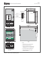
1
3714 Kinnear Place Saskatoon, SK Canada S7P 0A6 Ph: (306) 373-5505 Fx: (306) 374-2245 www.littelfuse.com/relayscontrols SE-701 MANUAL GROUND-FAULT MONITOR Revision 10-C-072414 Copyright © 2014 by Littelfuse Startco All rights reserved. Document Number: PM-1040-EN Printed in Canada. SE-701 Ground-Fault Monitor This page intentionally left blank. Page i Rev. 10-C-072414 Page ii Rev. 10-C-072414 SE-701 Ground-Fault Monitor TABLE OF CONTENTS SECTION LIST OF FIGURES PAGE Introduction ......................................................... 1 1.1 General .................................................................. 1 1.2 Current-Sensor Selection ...................................... 1 2 Operation ............................................................. 1 2.1 Configuration-Switch Settings .............................. 1 2.1.1 Relay Operating Mode ............................... 1 2.1.2 Trip Inhibit ................................................. 1 2.1.3 CT Verification .......................................... 1 2.1.4 Filter Selection ........................................... 1 2.1.5 Reset Mode ................................................ 1 2.2 Front-Panel Controls ............................................. 2 2.2.1 Ground-Fault Trip Level............................ 2 2.2.2 Ground-Fault Trip Time ............................ 2 2.2.3 Reset .......................................................... 2 2.2.4 Test ............................................................ 2 2.3 Front-Panel Indication .......................................... 2 2.3.1 Power ......................................................... 2 2.3.2 Trip ............................................................ 2 2.3.3 Trip Inhibit ................................................. 2 2.4 Analog Output....................................................... 2 2.5 Self Diagnostics .................................................... 2 3 Installation ........................................................... 3 4 SE-701 Compatibility.......................................... 6 5 Technical Specifications ................................... 14 6 Ordering Information ....................................... 16 7 Warranty ........................................................... 17 8 Ground-Fault Performance Test ..................... 18 Appendix A SE-701 Revision History......................... 20 1 FIGURE 1 2 3 4 5 6 7 8 9 10 11 12 PAGE SE-701 Outline and Mounting Details ...................4 Typical Connection Diagrams................................5 Typical Three-Phase-Starter Connection ...............5 EFCT-1 Outline and Mounting Details ..................7 EFCT-2 Outline and Mounting Details ..................8 EFCT-26 and SE-CS30-26 Outline and Mounting Details ..................................9 SE-CS30-70 Current Sensor .................................... 10 SE-CS30-4, -5, and -8 Current Sensors ................... 11 PMA-55 Panel-Mount Adapter ............................12 PMA-60 Panel-Mount Adapter ............................13 PGA-0500 Analog Percent Current Meter ...........14 Ground-Fault-Test Circuits ..................................18 LIST OF TABLES TABLE 1 2 PAGE Trip-Features Comparison .....................................6 Ground-Fault-Test Record ...................................19 DISCLAIMER Specifications are subject to change without notice. Littelfuse Startco is not liable for contingent or consequential damages, or for expenses sustained as a result of incorrect application, incorrect adjustment, or a malfunction. SE-701 Ground-Fault Monitor This page intentionally left blank. Page iii Rev. 10-C-072414 Page 1 Rev. 10-C-072414 SE-701 Ground-Fault Monitor 1. INTRODUCTION 1.1 GENERAL The SE-701 is a microprocessor-based ground-fault monitor for resistance-grounded and solidly grounded systems. It is uniquely suited for use on systems with significant harmonic content. Its output relay can operate in the fail-safe or non-fail-safe mode for undervoltage or shunt-trip applications. The SE-701 has one output relay with isolated normally open and normally closed contacts for use in independent control circuits. Additional features include LED trip, power, and inhibit indication, autoreset or latching trips with front-panel and remote reset, trip memory, test button, self diagnostics, 0- to 5-V analog output, inputs for ground-fault current sensors, CT verification for EFCT-series current sensors, digital selector switches, switch-selectable algorithms for fixedfrequency or variable-frequency applications, and an inhibit that can be enabled to prevent the output relay from operating during a high-current ground fault. Ground-fault current is sensed by a current transformer. Core-balance zero sequence current sensors (CT's) are most commonly used. Bus bar or toroid style CT's can also be used on the neutral to ground connection. See Fig. 2 in Technical Note CT-08 available at www.littelfuse.com. The trip level of the ground-fault circuit is switch selectable in 1% increments from 1 to 99% of the CT rating. 1.2 CURRENT-SENSOR SELECTION An SE-701 has inputs for 1-, 5-A, and 50-mA-secondary CT’s. Choose a CT that provides the required ground-faulttrip range. For ground-fault detection, the ground-fault trip level must be substantially below the prospective ground-fault current. In a solidly grounded system, prospective groundfault current is similar to phase-fault current. In a resistancegrounded system, prospective ground-fault current is defined by the neutral-grounding-resistor let-through-current rating. In a solidly grounded system, protection against arcing ground faults requires a ground-fault CT that will detect low-level fault current but not saturate up to the operating value of the system overcurrent protection. In general, immunity to saturation is proportional to CT mass. To eliminate nuisance tripping, surge current must not saturate the CT. For low-level ground-fault protection use an EFCT-1, EFCT-2, or EFCT-26 earth-fault CT with a 5-A-primary rating. However, protection at this level might not be possible because of high surge current or prospective ground-fault current. For CT-selection assistance, see Technical Note CT-01 available at www.littelfuse.com/relayscontrols. 2. OPERATION 2.1 CONFIGURATION-SWITCH SETTINGS See Fig. 1. 2.1.1 RELAY OPERATING MODE Switch 1 is used to set the operating mode of the output relay. In the fail-safe mode, the output relay energizes when the ground-fault circuit is not tripped. In the failsafe mode, non-volatile memory retains the trip status of the SE-701. If tripped, and the supply voltage is cycled, the SE-701 will remain tripped, with the trip relay de-energized and the TRIP LED on, until reset. In the non-fail-safe mode, the output relay energizes when a ground-fault trip occurs. In the non-fail-safe mode, trip status is not retained in non-volatile memory. 2.1.2 TRIP INHIBIT Switch 2 is used to select Class I or Class II operation. In the OFF position, high-current trip inhibit is off for Class I operation. In the ON position, high-current trip inhibit is on for Class II operation. If high-current trip inhibit is on and ground-fault current escalates above eleven times the CT-primary rating before the groundfault circuit trips, the output relay will not operate until ground-fault current falls below eight times the CTprimary rating. This feature allows overcurrent protection to operate in applications where the ground-fault current can be larger than the interrupting capacity of the device tripped by the SE-701. 2.1.3 CT VERIFICATION Switch 3 is used to enable CT verification with an EFCT-series CT. In the ON position, a trip will occur if the CT is disconnected. Switch 3 must be in the OFF position when an EFCT-series CT is not used and must be in the ON position when an EFCT is used. 2.1.4 FILTER SELECTION Switch 4 is used to select the filtering algorithm for a fixed-frequency (50/60 Hz) or variable-frequency application. The FIXED FREQUENCY setting uses a DFT filter that allows lower trip levels to be used by rejecting harmonics that can cause nuisance tripping. The VARIABLE FREQUENCY setting uses a peakdetection algorithm with a wider bandwidth for fault detection in variable-frequency drive applications. 2.1.5 RESET MODE Switch 5 is used to select autoreset or latching trips. See Section 2.2.3. SE-701 Ground-Fault Monitor 2.2 FRONT-PANEL CONTROLS 2.2.1 GROUND-FAULT TRIP LEVEL The % CT PRIMARY selector switches are used to set the ground-fault trip level as a percentage of the CT-primary rating. In tripping systems, a ground-fault trip level of 10 to 20% of the prospective ground-fault current is often used. In alarm-only systems, a value of 50% of the prospective ground-fault current is often used. To avoid sympathetic tripping, the trip level must be above the charging current of the protected feeder. A 0% selection provides protection at 1%. 2.2.2 GROUND-FAULT TRIP TIME The SE-701 has a definite-time trip characteristic. The TIME (s) selector switch is used to set the ground-fault trip delay time for coordination with upstream and downstream ground-fault devices. Coordination requires the same trip level for all ground-fault devices in a system and the trip time to progressively increase upstream. The amount of equipment removed from the system will be a minimum if the first ground-fault device to operate is the one immediately upstream from the fault. 2.2.3 RESET If the Reset Mode switch is in the LATCHING position, a trip remains latched until the RESET button is pressed or the remote-reset terminals are momentarily connected. In the non-fail-safe mode, cycling the supply voltage will also reset the SE-701. If the Reset Mode switch is in the AUTORESET position, a trip will reset when the fault is removed. The reset circuit responds only to a momentary closure so that a jammed or shorted button will not prevent a trip. The front-panel RESET button is inoperative when the remote-reset terminals (6 and 7) are connected. 2.2.4 TEST The TEST button is used to test the ground-fault circuit, the indication, and the output relay. When the TEST button is pressed for one second, a test signal is applied to the ground-fault-detection circuit, the circuit will trip, the TRIP LED will light, and the output relay will operate. If high-current inhibit has been selected, the INHB LED will light. 2.3 FRONT-PANEL INDICATION 2.3.1 POWER The green LED labelled PWR indicates the presence of supply voltage. 2.3.2 TRIP The red LED labelled TRIP indicates a trip. A solid red LED indicates a ground-fault trip. A flashing LED Page 2 Rev. 10-C-072414 indicates a trip initiated by a CT fault. Two fast flashes indicate a diagnostic trip. See Section 2.5. 2.3.3 TRIP INHIBIT The yellow LED labelled INHB indicates that outputrelay operation was inhibited during a high-current ground fault. See Section 2.1.2. When a ground-fault trip occurs during a high-current ground fault, both the TRIP and INHB LED’s will be ON. Inhibit indication is reset when the ground-fault trip is reset. Inhibit operation and indication will not respond if the trip-inhibit switch is in the OFF position. 2.4 ANALOG OUTPUT The non-isolated, 0- to 5-V analog output indicates ground-fault current sensed by the ground-fault CT. The output is 5 V when ground-fault current is 100% of the CT-primary rating. Use a PGA-0500 Analog Percent Current Meter with the PGA-05CV Voltage Converter to indicate ground-fault current. See Figs. 2, 3, and 11. 2.5 SELF DIAGNOSTICS A diagnostic trip is indicated by two fast flashes of the TRIP LED. It can be caused by a diagnostic problem detected by the watchdog timer or from an incorrect reading from non-volatile memory. Press RESET or cycle supply voltage. If the problem persists, contact Littelfuse Startco. SE-701 Ground-Fault Monitor 3. INSTALLATION Mounting, terminal-block connections, and NOTE: wiring must conform to applicable local electrical codes. Check all applicable codes prior to installation. An SE-701 can be surface or DIN-rail-mounted. See Fig. 1. Panel mounting requires a PMA-55 or PMA-60 Panel-Mount Adapter. See Figs. 9 and 10. Use terminal 11 (L1) as the line terminal on ac supply systems or the positive terminal on dc supply systems. Use Terminal 10 (L2/N) as the neutral terminal on ac systems or the negative terminal on dc systems. Connect terminal 9 ( ) to ground. Pass the phase conductors through the CT windowfor 4-wire and single-phase systems also pass the neutral conductor through the CT window, as shown in Figs. 2 and 3. Do not pass ground conductors through the CT window. In applications that require shields or drain wires to pass through the CT window, return them through the CT window before connecting them to ground. If a ground-fault CT with a 5-A secondary is used, connect it to terminals 2 and 3 (terminals 1 and 3 with a 1-A secondary) and ground terminal 3. If an EFCT-x is used, connect it to terminals 4 and 5, connect the shield to terminal 5, and ground terminal 5. Set configuration switch 3 to ON. Remove the connection to terminal 9 for dielectric-strength testing—all inputs and outputs have ANSI/IEEE C37.90 surge-protection circuits that conduct above 300 Vac. See Figs. 4, 5, and 6 for EFCT-series dimensional drawings and Figs. 6, 7, and 8 for the SE-CS30-series current sensors. Page 3 Rev. 10-C-072414 Page 4 Rev. 10-C-072414 SE-701 Ground-Fault Monitor 55.0 (2.17) 37.5 (1.48) 8.7 (0.34) CONFIGURATION SWITCHES AUTORESET FILTER SELECTION FIXED FREQUENCY 4 CT VERIFICATION 3 OFF OFF ON 1 RELAY OPERATING MODE FAIL-SAFE FILTER SELECTION FIXED FREQUENCY CT VERIFICATION OFF TRIP INHIBIT OFF 5 4 3 2 RELAY OPERATING MODE FAIL-SAFE 1 VARIABLE FREQUENCY 2 TRIP INHIBIT LATCHING NOTE 2 AUTORESET VARIABLE FREQUENCY ON ON 61.2 (2.41) 75.0 (2.95) CONFIGURATION SWITCHES 5 RESET MODE LATCHING RESET MODE NON-FAIL-SAFE ON NON-FAIL-SAFE S1 S2 RS 1 4 1A/5A CT 2 RESET ANALOG OUTPUT EFCT 3 5 6 7 MOUNTING DETAIL 8 118.0 (NOTE 3) (4.65) 110.0 (4.33) TOP 55.0 (2.17) LITTELFUSE STARTCO GROUND-FAULT MONITOR 5 INHB 6 7 8 9 4 3 2 1 5 0 0 % CT PRIMARY SE-701 TRIP 6 7 8 9 .40 .30 .20 .10 TEST .50 1.0 1.5 2.0 2.5 .05 TIME (s) 75.0 (2.95) PWR 4 3 2 1 6.3 (0.25) RESET FRONT SIDE NOTES: 9 10 11 12 13 14 15 16 L2 L1 N 1. DIMENSIONS IN MILLIMETRES (INCHES). 2. MOUNTING SCREWS: M4 OR 8-32. 3. OVERALL DIMENSION WHEN MOUNTED ON DINEN50022 35 mm x 7.5 mm TOP-HAT RAIL. 4. ADJUSTMENT KNOBS ARE REMOVABLE. BOTTOM FIGURE 1. SE-701 Outline and Mounting Details. 5. CONFIGURATION SWITCHES SHOWN IN DEFAULT POSITION. 6.9 1A 5A C (0.27) NOTE 5 Page 5 Rev. 10-C-072414 SE-701 Ground-Fault Monitor XXX:5 ØA XXX:5 ØA ØB ØB ØC ØC XXX:5 L N N N 14 N 14 2 3 1 L 11 3 2 5A C 4 5 S1 S2 L2 N L1 15 ISOLATED CONTACTS REMOTE RESET 6 SE-701 1-PHASE CONNECTION 3-PHASE, 4-WIRE CONNECTION 10 14 13 3 SE-701 N 1A 2 XXX:1 OR EFCT-X OR CS30-X 16 SE-701 RS RESET 7 1 LEAKAGE ANALOG OUTPUT 8 I PGA-05CV PGA-0500 9 PWR Y INHB R TRIP NOTE: 1. RELAY CONTACTS SHOWN WITH SE-701 DE-ENERGIZED. FIGURE 2. Typical Connection Diagrams. XXX:5 ØB ØC L N 1 3 2 1A 5A C 4 5 S1 S2 14 13 15 11 O/L 1M 1M SE-701 L2 N 10 RS RESET NOTES: 7 LEAKAGE I START 16 REMOTE RESET 6 STOP ISOLATED CONTACTS L1 ANALOG OUTPUT 8 PGA-05CV PGA-0500 9 1. RELAY CONTACTS SHOWN WITH SE-701 DE-ENERGIZED. INDICATION G PWR Y INHB R TRIP C 4 5 S1 S2 Technical Note CT-01 provides additional information on CT selection. 3-PHASE, 3-WIRE CONNECTION ØA 3 SE-701 INDICATION G 2 1A 5A FIGURE 3. Typical Three-Phase-Starter Connection. ALTERNATE CT CONNECTIONS Page 6 Rev. 10-C-072414 SE-701 Ground-Fault Monitor 4. SE-701 COMPATIBILITY The current SE-701 has been enhanced with the addition of non-volatile trip memory for the fail-safe relay operating mode. Prior to hardware revision 07, a mechanical flag was used instead of non-volatile trip memory. The current revision of the SE-701 can directly replace previous revision 00 to 06 units. Beginning with hardware revision 09, CT verification must be enabled when used with an EFCT-series earth-fault CT. Previous-revision SE-701 units used with EFCT-series CT’s can operate with CT verification enabled or disabled. See Section 2.1.3. The hardware-revision number is listed on the SE-701 model/serial-number label affixed to the SE-701 enclosure. The SE-701 generations are compared in Table 1. The SE-701 was previously available with SE-701-01 120-Vac and SE-701-02 240-Vac supply-voltage options. These have been discontinued. An SE-701-0U 120/240 Vac/Vdc unit can directly replace an SE-701-01 or SE-701-02. TABLE 1. TRIP-FEATURES COMPARISON HARDWARE REVISION LED trip indication Mechanical flag trip indication Non-volatile trip memory Device state after supply voltage cycled when tripped (ground-fault removed) CT Detection must be ON for EFCT Fail-safe Non-fail-safe 00 to 06 Yes Yes No Trip LED: Off Trip relay: Energized Trip flag: Red Trip LED: Off Trip relay: De-energized Trip flag: Red No 07 09 Yes No Yes Trip LED: On Trip relay: De-energized Trip LED: Off Trip relay: De-energized No Yes Page 7 Rev. 10-C-072414 SE-701 Ground-Fault Monitor NOTES: 1. DIMENSIONS IN MILLIMETRES (INCHES). 2. MOUNTING SCREWS: M4 OR 8-32. 3. PRESS MOUNTING FEET IN PLACE USING INSTALLATION TOOL PROVIDED. 4. RoHS COMPLIANT. 5. EN 60044-1 COMPLIANT. 121.0 (4.76) 121.0 (4.76) 20.5 (0.81) 56.0 (2.21) 46.0 (1.81) 30.0 (1.18) 80.0 (3.15) NOTE 2 M5 SCREWS TOP MOUNTING DETAIL 25.0 (0.98) 30.0 (1.18) EFCT-1 EARTH FA ULT CT 600 V CLASS, INSULATION CLASS A R R LR 53428 5.0 (0.20) Ø RECESSED FOR 8-mm HEX NUT 1.0 (0.04) DEEP 22.0 (0.87) EFCT - 1FC FLUX CONDITIONER (OPTIONAL) .0 82 23) . 3 ( 69. (2.7 8 5) 126.0 (4.96) US (5.43) 138.0 MAX C 5.5 (0.22) 110.0 (4.33) FRONT FIGURE 4. EFCT-1 Outline and Mounting Details. 5.5 (0.22) 56.0 (2.21) SIDE Page 8 Rev. 10-C-072414 SE-701 Ground-Fault Monitor NOTES: 1. DIMENSIONS IN MILLIMETRES (INCHES). 2. MOUNTING SCREWS: M5 OR 10-32. 3. RoHS COMPLIANT. 4. EN 60044-1 COMPLIANT. 215.0 (8.46) 26.5 (1.04) 52.3 (2.06) P S1 2S2 P1 31.0 (1.22) 64.0 (2.52) 215.0 (8.46) 162.0 (6.38) M5 OR 10-32 TAP M5 SCREWS TOP MOUNTING DETAIL 31.0 (1.22) 25.0 (0.98) EFCT-2 EARTH FAULT CT 600 V CLASS, INSULATION CLASS A R R LR 53428 139.7 (5.50) FLUX CONDITIONER (INCLUDED) BONDING SCREW 215.0 (8.46) US 5.0 (0.20) DIA 60.0 (2.36) 236 MAX (9.29) C 8.5 (0.33) 198.0 (7.80) FRONT FIGURE 5. EFCT-2 Outline and Mounting Details. 8.5 (0.33) SIDE Page 9 Rev. 10-C-072414 SE-701 Ground-Fault Monitor 68.0 (2.68) 34.0 (1.34) 68.0 (2.68) M4 OR 8-32 TAP 26.5 (1.04) 52.5 (2.07) 42.6 (1.68) 17.0 (0.67) MOUNTING DETAIL TOP (0.43) 110.0 MAX M5 SCREWS 25.0 (0.98) 26.5 (1.04) SE-CS30-26 CURRENT SENSOR R R LR 53428 US 4.0 (0.16) Ø 0 . 26 RECESSED FOR 7-mm HEX NUT 3.0 (0.12) DEEP 2) 7.0 .0 (1 58.0 (2.28) (0.87) 34.0 (1.34) 72.0 (2.83) C 5.0 (0.20) 5.0 (0.20) 52.5 (2.07) FRONT SIDE NOTES: 1. DIMENSIONS IN MILLIMETRES (INCHES). 2. PRESS MOUNTING FEET IN PLACE USING INSTALLATION TOOL PROVIDED (DETAIL ‘A’). MOUNTING FOOT INSTALLA TION TOOL 3. MOUNTING SCREWS: M4 OR 8-32. 4. RoHS COMPLIANT. 5. EN 60044-1 COMPLIANT. DETAIL ‘A’ 6. SE-CS30-26 SHOWN. FIGURE 6. EFCT-26 and SE-CS30-26 Outline and Mounting Details. Page 10 Rev. 10-C-072414 SE-701 Ground-Fault Monitor 121.0 (4.76) 121.0 (4.76) 20.5 80.0 (3.15) 56.0 (2.21) 46.0 (1.81) 30.0 (1.18) (0.81) NOTE 3 M5 SCREWS TOP MOUNTING DETAIL 25.0 (0.98) (1.18) 30.0 SE-CS30-70 CURRENT SENSOR R LR 53428 R 22.0 Ø 5.0 (0.20) RECESSED FOR 8-mm HEX NUT 1.0 (0.04) DEEP 5.5 110.0 5.5 (0.22) (4.33) (0.22) 56.0 (2.21) SIDE FRONT MOUNTING FOOT INSTALLATION TOOL 126.0 69. 8 (2.7 5) (4.96) US (0.87) (5.43) 138.0 MAX C NOTES: 1. DIMENSIONS IN MILLIMETRES (INCHES). 2. PRESS MOUNTING FEET IN PLACE USING INSTALLATION TOOL PROVIDED (DETAIL ‘A’). 3. MOUNTING SCREWS: M4 OR 8-32. DETAIL ‘A’ FIGURE 7. SE-CS30-70 Current Sensor. 4. RoHS COMPLIANT. 5. EN 60044-1 COMPLIANT. Page 11 Rev. 10-C-072414 SE-701 Ground-Fault Monitor C D H G J 14.0 (0.55) 72.0 (2.83) F TOP (COVER REMOVED) MOUNTING DETAIL NOTES: SE-CS30-8 OUTLINE 1. DIMENSIONS IN MILLIMETRES (INCHES). 2. MOUNTING SCREWS: M5 OR 10-32. 3. RoHS COMPLIANT. B A 4. CE COMPLIANT. DIMENSIONS I L D C BOTTOM FIGURE 8. SE-CS30-4, -5, and -8 Current Sensors. J K G FRONT 1.7 (0.07) E FLUX CONDITIONER SE-CS30-4 SE-CS30-5 SE-CS30-8 A 95.0 (3.74) 130.0 (5.12) 200.0 (7.87) B 175.0 (6.89) 218.0 (8.78) 309.0 (12.17) C 158.0 (6.22) 203.0 (7.99) 290.5 (11.44) D 141.0 (5.55) 178.0 (7.01) 267.5 (10.50) E 82.0 (3.22) 103.5 (4.07) 150.0 (5.90) F 32.0 (1.26) 32.0 (1.26) 34.0 (1.34) G 17.5 (0.69) 11.0 (0.43) 11.0 (0.43) H 15.0 (0.59) 13.3 (0.52) 13.3 (0.52) I 33.0 (1.30) 34.0 (1.34) 43.0 (1.69) J 9.0 (0.35) 11.0 (0.43) 11.5 (0.45) K 40.0 (1.57) 40.0 (1.57) 50.0 (1.97) L 5.3 (0.21) 7.0 (0.28) 7.0 (0.28) Page 12 Rev. 10-C-072414 SE-701 Ground-Fault Monitor 110.0 (4.33) 85.0 PANEL THICKNESS 1.6 (0.06) TO 4.8 (0.19) (3.35) 5 6 7 8 9 4 3 2 1 5 0 0 % CT PRIMARY SE-701 TRIP 6 7 8 9 .40 .30 .20 .10 .50 1.0 1.5 2.0 2.5 .05 TIME (s) TEST 75.0 4 3 2 1 INHB 6-32 RESET BRACKET 6.0 (0.24) 2.0 (0.08) RAD MAXIMUM 55.0 (2.20) WIDE MONITOR SIDE VIEW INSTALLATION INSTRUCTIONS: 1. REMOVE BEZEL AND LATCH MONITOR ON BRACKET. 2. INSERT BRACKET THROUGH FRONT OF PANEL CUTOUT AND SECURE WITH FLAT WASHERS AND LOCKNUTS PROVIDED. 4.0 (0.16) DIA 8.7 (0.34) DIA 4.3 (0.17) RAD 60.0 (2.36) 79.0 (3.11) 42.5 (1.67) 30.0 (1.18) 85.0 (3.35) 72.0 (2.83) 60.0 (2.36) BEZEL 9.5 (0.37) FRONT VIEW 6.0 (0.24) (2.95) PWR 85.0 (3.35) 42.5 (1.67) 6-32 LITTELFUSE STARTCO GROUND-FAULT MONITOR ALTERNATE CONFIGURATIONS 3. CONNECT WIRING TO TERMINALS. 4. INSTALL BEZEL USING 6-32 x 0.31 SCREWS PROVIDED. NOTE: 9.5 (0.37) 1. DIMENSIONS IN MILLIMETRES (INCHES). PANEL CUTOUT DETAIL FIGURE 9. PMA-55 Panel-Mount Adapter. Page 13 Rev. 10-C-072414 SE-701 Ground-Fault Monitor 116.0 (4.57) 99.0 (3.90) PANEL THICKNESS 1.6 (0.06) TO 4.8 (0.19) 5 6 7 8 9 4 3 2 1 5 0 0 % CT PRIMARY SE-701 TRIP 6 7 8 9 .40 .30 .20 .10 TEST .50 1.0 1.5 2.0 2.5 .05 TIME (s) 75.0 4 3 2 1 INHB M4 RESET BRACKET TRANSPARENT COVER (NOTE 2) FRONT VIEW 6.0 (0.24) 2.0 (0.08) RAD MAXIMUM 1. WITH COVER REMOVED LATCH MONITOR TO BRACKET. 2. INSERT BRACKET THROUGH FRONT OF PANEL CUTOUT AND SECURE WITH FLAT WASHERS AND LOCKNUTS PROVIDED. 3. CONNECT WIRING TO TERMINALS. 4.5 (0.18) DIA 8.7 (0.34) DIA 4.3 (0.17) RAD 60.0 (2.36) 79.0 (3.11) 44.0 (1.73) 30.0 (1.18) SIDE VIEW INSTALLATION INSTRUCTIONS: 9.5 (0.37) 6.0 (0.24) 99.0 (3.90) 72.0 (2.83) 60.0 (2.36) 55.0 (2.20) WIDE MONITOR ALTERNATE CONFIGURATIONS 4. ATTACH COVER USING SECURITY SCREWS OR THUMB SCREWS PROVIDED. NOTES: 1. DIMENSIONS IN MILLIMETRES (INCHES). 9.5 (0.37) 2. MEETS NEMA3, IP53. PANEL CUTOUT DETAIL FIGURE 10. PMA-60 Panel-Mount Adapter. 3. INCLUDES TWO TR20 TAMPER-RESISTANT TORX SCREWS (M4-0.7x16 mm, INSTALLED) AND TWO THUMB SCREWS. (2.95) PWR 88.0 (3.46) 44.0 (1.73) M4 LITTELFUSE STARTCO GROUND-FAULT MONITOR Page 14 Rev. 10-C-072414 SE-701 Ground-Fault Monitor 67.5 (2.657) 67.5 (2.657) 48.0 (1.890) 66.0 (2.598) R1.25(0.049) MAXIMUM NOTES: 1. CONVERSION KIT FOR 0-5 V ANALOG OUTPUT. SEE PGA-0500 DOCUMENTATION. 2. DIMENSIONS IN MILLIMETRES (INCHES). TOP % MOUNTING CUTOUT NOTE 1 100 ® 20 65.0 (2.559) 60 40 71.0 (2.795) 80 0 PGA-0500 ANALOG % CURRENT METER FRONT SIDE REAR FIGURE 11. PGA-0500 Analog Percent Current Meter. 5. TECHNICAL SPECIFICATIONS Supply: 0U Option ..............................5 VA, 120 to 240 Vac, (+20, -55%) 50/60 Hz; 2 W, 100 to 240 Vdc, (+20, -25%) 0D Option ..............................2 W, 12 to 30 Vdc, (+20, -25%) 0T Option ...............................2 W, 40 to 55 Vdc, (+20, -25%) 03 Option ...............................2.5 VA, 24 Vac, (+15, -40%), 50/60 Hz Trip-Level Range.........................1 to 99% CT-Primary Rating in 1% increments (50 mA to 4.95 A with EFCT-x) Trip-Time Settings.......................0.05, 0.10, 0.20, 0.30, 0.40, 0.50, 1.0, 1.5, 2.0, and 2.5 s Accuracies (1): Trip Level (2) .......................... Largest of 5% of setting or: 1-A input: 1% setting ........................ -10, +15 mA 2 - 99% setting ................. 10 mA 5-A and EFCT (4) inputs: 1% setting ........................ -35, +60 mA 2 - 99% setting ................. 35 mA Trip Time (3) ........................... 5% of setting (-25, +20 ms minimum) Trip Inhibit: Off ......................................... Class I On ......................................... Class II Level ................................... 11 x CT-Primary Rating Input: Algorithms ............................. DFT or Peak DFT 3 dB Frequency Resp ... 32 to 86 Hz Peak 3 dB Frequency Resp ... 20 to 420 Hz CT ......................................... 1- or 5-A Secondary Rating, or EFCT-x CT Detection ...................... Open-Circuit Detection with EFCT-x SE-701 Ground-Fault Monitor Thermal Withstand: Continuous ......................... 5 x CT-Secondary Rating 1-Second ............................ 80 x CT-Secondary Rating Burden: 5-A input ............................ < 0.01 1-A input ............................ < 0.05 EFCT input ........................ 2 Analog Output: Range .................................... 0 to 5 Vdc, 5 V = 100% CT Rating Output Impedance ................ 220 Reset ..........................................Front-Panel Button and Remote N.O. Momentary Contact Page 15 Rev. 10-C-072414 Environment: Operating Temperature: Altitude: ≤ 1,000 m (3,281’) ........ -40 to 60C (-40 to 140°F) 3,000 m (9,843’) ........... -40 to 55C (-40 to 131°F) 5,000 m (16,404’) ......... -40 to 50C (-40 to 122°F) Storage Temperature ........... -55 to 80C (-67 to 160°F) Humidity ................................ 85% Non-Condensing Altitude................................... 5,000 m (16,404’) maximum PWB Conformal Coating............ MIL-1-46058 qualified UL QMJU2 recognized Functional Test ............................Front-Panel Button Output Relay: Contact Configuration ....... Isolated N.O. and N.C. Operating Mode ................. Fail-Safe or Non-Fail-Safe CSA/UL Contact Rating .... 8 A General Use, 250 Vac, 8 A Resistive, 30 Vdc 0.25 HP, 120/240 Vac Supplemental Contact Ratings: Carry Current .................. 8 A, maximum Break: 30 Vdc .......................... 240 W Resistive, 170 W Inductive (L/R = 7 ms) 120 Vdc ........................ 24 W Resistive, 17 W Inductive (L/R = 7 ms) ac .................................. 2,000 VA Resistive, 875 VA Inductive (PF = 0.4) (Subject to maximums of 8 A and 250 Vac/ 30 Vdc or 200 mA at 120 Vdc) Trip Mode ....................................Latching or Autoreset Terminals .....................................Wire-clamping, 24 to 12 AWG (0.2 to 2.5 mm2) conductors Dimensions: Height.................................... 75 mm (3.0”) Width .................................... 55 mm (2.2”) Depth ..................................... 113 mm (4.5”) Shipping Weight ..........................0.45 kg (1 lb) Surge Withstand .......................... ANSI/IEEE 37.90.1-1989 (Oscillatory and Fast Transient) Vibration ...................................... EN60255-21-1 (Vibration, Shock, and Seismic) EN60255-21-2 (Shock and Bump) EMC Tests: Verification tested in accordance with EN 50263:2000 Radiated and Conducted Emissions ........................... CISPR 11:2009, CISPR 22:2008, EN55022:2010 Class A Current Harmonics and Voltage Fluctuation ............ IEC 61000-3-2 and IEC 61000-3-3 Class A Electrostatic Discharge ....... IEC 61000-4-2 ± 6 kV contact discharge (direct and indirect) ± 8 kV air discharge Radiated RF Immunity ........ IEC 61000-4-3 10 V/m, 80-1000 MHz, 80% AM (1 kHz) 10 V/m, 900 MHz, 200 Hz pulse modulated Page 16 Rev. 10-C-072414 SE-701 Ground-Fault Monitor Fast Transient ...................... IEC 61000-4-4 4 kV on AC mains and I/O lines Certification ................................. CSA, Canada and USA R C LR 53428 US UL Listed Surge Immunity .................. IEC 61000-4-5 Zone B ± 1 kV differential mode ± 2 kV common mode Australia Conducted RF Immunity .... IEC 61000-4-6 10 V, 0.15-80 MHz, 80% AM (1 kHz) N11659 Magnetic Field Immunity ... IEC 61000-4-8 50 Hz and 60 Hz , 30 A/m and 300 A/m CE, European Union Voltage Interruption ........... IEC 61000-4-11, IEC 61000-4-29, 0% for 5, 10, 20, 50, 100 & 200 ms 3x each Power Frequency ................ IEC 61000-4-16 Zone A: differential mode 150 Vrms Zone A: common mode 300 Vrms 1 MHz Burst ....................... IEC 61000-4-18 ± 1 kV differential mode (line-to-line) ± 2.5 kV common mode RFI Compliance ....................... FCC Part 15, Subpart B, Class A – Unintentional Radiators FCC Complies to IEC 61010-1:2001 (2nd Edition); EN 61010-1:2001 (2nd Edition) Safety Requirements for Electrical Equipment for Measurement, Control, and Laboratory Use – Part 1. NOTES: (1) Over operating temperature range of -40 to 60°C (-40 to 140°F). (2) CT accuracy not included. (3) Trip time at 3 x trip-level setting from the first peak. (4) For maximum lead resistance of 1 . 6. ORDERING INFORMATION SE-701-0 Conformal Coating: Blank – Partial Conformal Coating CC – Full Conformal Coating Supply: 3 – 24-Vac Supply U – Universal 120/240-Vac/Vdc Supply D – 12/24-Vdc Supply T – 48-Vdc Supply EFCT-1 ........................................ Earth-Fault CT, 5-A-primary rating, 82 mm (3.2”) window EFCT-1FC ................................... Flux Conditioner for EFCT-1, 70 mm (2.7”) window EFCT-2 ........................................ Earth-Fault CT, with Flux Conditioner, 5-A-primary rating, 139 mm (5.5”) window EFCT-26 ...................................... Earth-Fault CT, 5-A-primary rating, 26 mm (1”) window (All EFCT’s include 6 m (19.2’) 22 AWG (0.3 mm2) shielded cable.) Page 17 Rev. 10-C-072414 SE-701 Ground-Fault Monitor SE-CS30-26 .................................Current Sensor, 26.0 mm (1.02”) window SE-CS30-70 .................................Current Sensor c/w Flux Conditioner, 69.8 mm (2.75”) window SE-CS30-4 ...................................Current Sensor c/w Flux Conditioner, 95.0 mm (3.74”) window SE-CS30-5 ...................................Current Sensor c/w Flux Conditioner, 130.0 mm (5.12”) window SE-CS30-8 ...................................Current Sensor c/w Flux Conditioner, 200.0 mm (7.87”) window 5SHT-101-E(1) .............................Current Sensor, 100-A-primary rating, 40 mm (1.6”) window 5SHT-151-E(1) .............................Current Sensor, 150-A-primary rating, 40 mm (1.6”) window 5SHT-500-E(1) .............................Current Sensor, 50-A-primary rating, 40 mm (1.6”) window 7SHT-301-E(1) .............................Current Sensor, 300-A-primary rating, 64 mm (2.5”) window 7SHT-401-E(1) .............................Current Sensor, 400-A-primary rating, 64 mm (2.5”) window PGA-0500 ....................................Analog Percent Current Meter (PGA-05CV included) PMA-55 .......................................Panel-Mount Adapter, NEMA 1 PMA-60 .......................................Panel-Mount Adapter, NEMA 3, IP53. Includes two TR20 tamper-resistant Torx screws and two thumb screws. PMA-3 .........................................Adapter Plate, GES/MCGG PMA-6 .........................................Adapter Plate, FPL-GFRM PMA-15 .......................................Adapter Plate, MGFR SE-EFVC .....................................Voltage Clamp Consult factory for custom mounting adapters. NOTES: (1) Includes mounting brackets. 7. WARRANTY The SE-701 Ground-Fault Monitor is warranted to be free from defects in material and workmanship for a period of five years from the date of purchase. Littelfuse Startco will (at Littelfuse Startco’s option) repair, replace, or refund the original purchase price of an SE-701 that is determined by Littelfuse Startco to be defective if it is returned to the factory, freight prepaid, within the warranty period. This warranty does not apply to repairs required as a result of misuse, negligence, an accident, improper installation, tampering, or insufficient care. Littelfuse Startco does not warrant products repaired or modified by nonLittelfuse Startco personnel. Page 18 Rev. 10-C-072414 SE-701 Ground-Fault Monitor 8. GROUND-FAULT PERFORMANCE TEST a) USING SE-400 To meet the requirements of the National Electrical Code (NEC), as applicable, the overall ground-fault protection system requires a performance test when first installed. A written record of the performance test is to be retained by those in charge of the electrical installation in order to make it available to the authority having jurisdiction. A test-record form is provided for recording the date and the final results of the performance tests. The following ground-fault system tests are to be conducted by qualified personnel: FROM POWER SOURCE c) Verify that the system is correctly grounded and that alternate ground paths do not exist that bypass the current sensor. High-voltage testers and resistance bridges can be used to determine the existence of alternate ground paths. d) Verify proper reaction of the circuit-interrupting device in response to a simulated or controlled ground-fault current. To simulate ground-fault current, use CT-primary current injection. Fig. 12 (a) shows a test circuit using an SE-400 Ground-FaultRelay Test Unit. The SE-400 has a programmable output of 0.5 to 9.9 A for a duration of 0.1 to 9.9 seconds. Set the test current to 120% of the SE-701 setting. Fig. 12 (b) shows a test circuit using an SE-100T Ground-Fault-Relay Tester. The SE-100T provides a test current of 0.65 or 2.75 A for testing 0.5- and 2.0-A trip levels. Inject the test current through the current-sensor window for at least 2.5 seconds. Verify that the circuit under test has reacted properly. Correct any problems and re-test until the proper reaction is verified. e) Record the date and the results of the test on the attached test-record form. NOTE: Do not inject test current directly into CT-input terminals 1, 2, 3, 4, and 5. LOAD 1 2 3 1A 5A C L 11 N 10 11 a) Evaluate the interconnected system in accordance with the overall equipment manufacturer’s detailed instructions. b) Verify proper location of the ground-fault current sensor. Ensure the cables pass through the groundfault-current-sensor window. This check can be done visually with knowledge of the circuit. The connection of the current-sensor secondary to the SE701 is not polarity sensitive. XXX:5 L N 3 5 L1 L2/N 8 9 5 S1 S2 SE-701 OP1 OP2 L2 SE-400 RMT1 RMT2 b) USING SE-100T XXX:5 FROM POWER SOURCE LOAD 1 2 3 1A 5A C REMOTE TEST 12 L1 1 REMOTE TEST 4 L 11 N 10 L1 L2/N 4 5 S1 S2 SE-701 C LO L L1 HI N L2 SE-100T RMT FIGURE 12. Ground-Fault-Test Circuits. 0.65 A 2.75 A SE-701 Ground-Fault Monitor TABLE 2. GROUND-FAULT-TEST RECORD DATE TEST RESULTS Retain this record for the authority having jurisdiction. Page 19 Rev. 10-C-072414 Page 20 Rev. 10-C-072414 SE-701 Ground-Fault Monitor MANUAL RELEASE DATE APPENDIX A SE-701 REVISION HISTORY MANUAL PRODUCT REVISION REVISION (REVISION NUMBER ON PRODUCT LABEL) July 24, 2014 10-C-072414 October 21, 2013 10-B-102113 April 12, 2013 10-A-041213 MANUAL REVISION HISTORY REVISION 10-C-072414 SECTION 4 Fig. 8 updated. SECTION 5 Update to include altitude and vibration specifications. APPENDIX A Revision history updated. REVISION 10-B-102113 SECTION 4 Fig. 6 updated to include EFCT-26 and SE-CS30-26. SECTION 5 Conformal coating specifications added. FCC certification mark added. SECTION 6 Updated ordering information with full conformal coating (CC) option. APPENDIX A Revision history updated. REVISION 10-A-041213 SECTION 3 Figs. 2 and 3 updated to include PGA-05CV. SECTION 4 Figs. 7, 8, and 9 added. SECTION 5 Environment section updated to include Fahrenheit temperature range. SECTION 6 Additional current sensors added to ordering information. APPENDIX A Revision history added. PRODUCT REVISION HISTORY REVISION 09 Firmware: Improved operation of front-panel test button. 09