1
ABI PRISM® 3100 Genetic Analyzer
Quick Start Guide for Fragment Analysis
© Copyright 2001, Applied Biosystems.
All rights reserved.
For Research Use Only. Not for use in diagnostic procedures.
Information in this document is subject to change without notice. Applied Biosystems assumes no responsibility for any errors that may appear in this
document. This document is believed to be complete and accurate at the time of publication. In no event shall Applied Biosystems be liable for incidental,
special, multiple, or consequential damages in connection with or arising from the use of this document.
FOR LIMITED LICENSE INFORMATION, PLEASE SEE THE ABI PRISM ® 3100 GENETIC ANALYZER USER’S MANUAL.
The ABI PRISM® 3100 Genetic Analyzer includes patented technology licensed from Hitachi, Ltd. as part of a strategic partnership between Applied
Biosystems and Hitachi, Ltd., as well as patented technology of Applied Biosystems.
ABI PRISM and its design, Applied Biosystems, BioLIMS, GeneScan, GeneMapper, Genotyper, and MicroAmp are registered trademarks of Applera
Corporation or its subsidiaries in the U.S. and certain other countries.
ABI, BigDye, Factura, Hi-Di, POP, POP-4, and POP-6 are trademarks of Applera Corporation or its subsidiaries in the U.S. and certain other countries.
AmpliTaq is a registered trademark of Roche Molecular Systems, Inc.
Microsoft, Windows, and Windows NT are registered trademarks of the Microsoft Corporation in the United States and other countries.
Oracle is a registered trademark of the Oracle Corporation.
pGEM is a registered trademark of Promega Corporation.
All other trademarks are the sole property of their respective owners.
Printed in the USA, 07/2001
Part Number 4315832 Rev. C
Contents
1 Introduction
Overview . . . . . . . . . . . . . . . . . . . . . . . . . . . . . . . . . . . . . . . . . . . . . . . . . . . . . . . . . . . . . . . . . . 1-1
About This Manual. . . . . . . . . . . . . . . . . . . . . . . . . . . . . . . . . . . . . . . . . . . . . . . . . . . . . . . . . . . 1-2
For More Information. . . . . . . . . . . . . . . . . . . . . . . . . . . . . . . . . . . . . . . . . . . . . . . . . . . . . . . . . 1-2
Safety . . . . . . . . . . . . . . . . . . . . . . . . . . . . . . . . . . . . . . . . . . . . . . . . . . . . . . . . . . . . . . . . . . . . . 1-3
2 Performing a Fragment Analysis Run
Overview . . . . . . . . . . . . . . . . . . . . . . . . . . . . . . . . . . . . . . . . . . . . . . . . . . . . . . . . . . . . . . . . . . 2-1
Before You Begin . . . . . . . . . . . . . . . . . . . . . . . . . . . . . . . . . . . . . . . . . . . . . . . . . . . . . . . . . . . . 2-2
ABI PRISM ® 3100 Genetic Analyzer - User Flowchart for Fragment Analysis. . . . . . . . . . . . . 2-3
Sample Preparation. . . . . . . . . . . . . . . . . . . . . . . . . . . . . . . . . . . . . . . . . . . . . . . . . . . . . . . . . . . 2-4
Starting the Data Collection Software . . . . . . . . . . . . . . . . . . . . . . . . . . . . . . . . . . . . . . . . . . . . 2-6
Setting Software Preferences . . . . . . . . . . . . . . . . . . . . . . . . . . . . . . . . . . . . . . . . . . . . . . . . . . . 2-8
Working with Plate Assemblies . . . . . . . . . . . . . . . . . . . . . . . . . . . . . . . . . . . . . . . . . . . . . . . . 2-11
Checking and Refilling Fluids . . . . . . . . . . . . . . . . . . . . . . . . . . . . . . . . . . . . . . . . . . . . . . . . . 2-13
Placing the Plate onto the Autosampler . . . . . . . . . . . . . . . . . . . . . . . . . . . . . . . . . . . . . . . . . . 2-17
Creating a Plate Record . . . . . . . . . . . . . . . . . . . . . . . . . . . . . . . . . . . . . . . . . . . . . . . . . . . . . . 2-18
Linking and Unlinking a Plate . . . . . . . . . . . . . . . . . . . . . . . . . . . . . . . . . . . . . . . . . . . . . . . . . 2-24
Starting and Monitoring the Run . . . . . . . . . . . . . . . . . . . . . . . . . . . . . . . . . . . . . . . . . . . . . . . 2-27
Stopping a Run and Recovering the Data. . . . . . . . . . . . . . . . . . . . . . . . . . . . . . . . . . . . . . . . . 2-28
Viewing, Editing, or Creating a Run Module. . . . . . . . . . . . . . . . . . . . . . . . . . . . . . . . . . . . . . 2-29
About Viewing and Editing Modules for GeneScan Analysis . . . . . . . . . . . . . . . . . . . . . . . . . 2-31
3 Viewing and Analyzing Data
Overview . . . . . . . . . . . . . . . . . . . . . . . . . . . . . . . . . . . . . . . . . . . . . . . . . . . . . . . . . . . . . . . . . . 3-1
Viewing Raw Data from a Completed Run in the Data Collection Software . . . . . . . . . . . . . . 3-2
Viewing Analyzed Data in GeneScan Software . . . . . . . . . . . . . . . . . . . . . . . . . . . . . . . . . . . . . 3-5
Analyzing or Reanalyzing Data in GeneScan Software. . . . . . . . . . . . . . . . . . . . . . . . . . . . . . 3-12
4 Spatial and Spectral Calibrations
Overview . . . . . . . . . . . . . . . . . . . . . . . . . . . . . . . . . . . . . . . . . . . . . . . . . . . . . . . . . . . . . . . . . . 4-1
Performing a Spatial Calibration . . . . . . . . . . . . . . . . . . . . . . . . . . . . . . . . . . . . . . . . . . . . . . . . 4-2
Performing a Spectral Calibration . . . . . . . . . . . . . . . . . . . . . . . . . . . . . . . . . . . . . . . . . . . . . . . 4-6
iii
5 Maintaining the Instrument
Overview . . . . . . . . . . . . . . . . . . . . . . . . . . . . . . . . . . . . . . . . . . . . . . . . . . . . . . . . . . . . . . . . . . 5-1
Maintenance Task Lists . . . . . . . . . . . . . . . . . . . . . . . . . . . . . . . . . . . . . . . . . . . . . . . . . . . . . . . 5-2
Removing Air Bubbles from the Upper Polymer Block . . . . . . . . . . . . . . . . . . . . . . . . . . . . . . 5-4
Checking the Available Disk Space . . . . . . . . . . . . . . . . . . . . . . . . . . . . . . . . . . . . . . . . . . . . . . 5-6
Cleaning and Inspecting Syringes . . . . . . . . . . . . . . . . . . . . . . . . . . . . . . . . . . . . . . . . . . . . . . . 5-8
Removing the Polymer Blocks . . . . . . . . . . . . . . . . . . . . . . . . . . . . . . . . . . . . . . . . . . . . . . . . . 5-10
Cleaning the Polymer Blocks . . . . . . . . . . . . . . . . . . . . . . . . . . . . . . . . . . . . . . . . . . . . . . . . . . 5-11
Putting Fresh Polymer on the Instrument. . . . . . . . . . . . . . . . . . . . . . . . . . . . . . . . . . . . . . . . . 5-12
Before Installing a Previously Used Capillary Array. . . . . . . . . . . . . . . . . . . . . . . . . . . . . . . . 5-14
Installing and Removing the Capillary Array . . . . . . . . . . . . . . . . . . . . . . . . . . . . . . . . . . . . . 5-15
Storing a Capillary Array . . . . . . . . . . . . . . . . . . . . . . . . . . . . . . . . . . . . . . . . . . . . . . . . . . . . . 5-16
Shutting Down the Instrument . . . . . . . . . . . . . . . . . . . . . . . . . . . . . . . . . . . . . . . . . . . . . . . . . 5-17
A Preparing Formamide
Deionizing and Storing Formamide . . . . . . . . . . . . . . . . . . . . . . . . . . . . . . . . . . . . . . . . . . . . . .A-1
B Getting Help
Technical Support . . . . . . . . . . . . . . . . . . . . . . . . . . . . . . . . . . . . . . . . . . . . . . . . . . . . . . . . . . . .B-1
Index
iv
Introduction
1
1
Overview
In This Chapter This chapter includes the following topics:
Topic
See Page
About This Manual
1-2
For More Information
1-2
Safety
1-3
Introduction 1-1
About This Manual
Purpose The purpose of this manual is to give users basic instructions on how to:
Do a fragment analysis run
Analyze the resulting data
Calibrate and perform routine maintenance on the ABI PRISM ® 3100 Genetic
Analyzer
For More Information
Where to Find More Other manuals and guides that relate to the 3100 Genetic Analyzer are listed below.
Information
Part
Number
If you want…
Refer to the…
safety information and information about preparing
your lab for the 3100 Genetic Analyzer
ABI PRISM 3100 Genetic Analyzer Site Preparation
and Safety Guide
4315835
detailed information about the 3100 Genetic
Analyzer
ABI PRISM 3100 Genetic Analyzer User’s Manual
4315834
detailed information about analyzing and viewing
fragment data using the ABI PRISM ® GeneScan ®
Analysis Software or the ABI PRISM ®
GeneMapper ® Analysis Software
ABI PRISM GeneScan Analysis Software v. 3.7
User Guide
4308923
an abbreviated procedure for how to do a typical
sequencing run, view and analyzer run data, and
perform common maintenance operations
ABI PRISM 3100 Genetic Analyzer Quick Start
Guide for Sequencing
4315833
information on a procedure for block cleaning
ABI PRISM 3100 Genetic Analyzer Block Cleaning
Procedure
4322930
1-2 Introduction
Safety
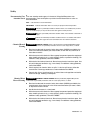
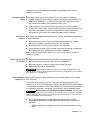
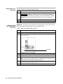
Documentation User Five user attention words appear in the text of all Applied Biosystems user
Attention Words documentation. Each word implies a particular level of observation or action as
described below.
Note
Calls attention to useful information.
IMPORTANT Indicates information that is necessary for proper instrument operation.
! CAUTION Indicates a potentially hazardous situation which, if not avoided, may result in
minor or moderate injury. It may also be used to alert against unsafe practices.
! WARNING Indicates a potentially hazardous situation which, if not avoided, could result in
death or serious injury.
! DANGER Indicates an imminently hazardous situation which, if not avoided, will result in
death or serious injury. This signal word is to be limited to the most extreme situations.
Chemical Hazard ! WARNING CHEMICAL HAZARD. Some of the chemicals used with Applied Biosystems
Warning instruments and protocols are potentially hazardous and can cause injury, illness, or death.
Read and understand the material safety data sheets (MSDSs) provided by the
chemical manufacturer before you store, handle, or work with any chemicals or
hazardous materials.
Minimize contact with chemicals. Wear appropriate personal protective equipment
when handling chemicals (e.g., safety glasses, gloves, or protective clothing). For
additional safety guidelines, consult the MSDS.
Minimize the inhalation of chemicals. Do not leave chemical containers open. Use
only with adequate ventilation (e.g., fume hood). For additional safety guidelines,
consult the MSDS.
Check regularly for chemical leaks or spills. If a leak or spill occurs, follow the
manufacturer’s cleanup procedures as recommended on the MSDS.
Comply with all local, state/provincial, or national laws and regulations related to
chemical storage, handling, and disposal.
\
Chemical Waste ! WARNING CHEMICAL WASTE HAZARD. Wastes produced by Applied Biosystems
Hazard Warning instruments are potentially hazardous and can cause injury, illness, or death.
Read and understand the material safety data sheets (MSDSs) provided by the
manufacturers of the chemicals in the waste container before you store, handle,
or dispose of chemical waste.
Handle chemical wastes in a fume hood.
Minimize the inhalation of chemicals. Do not leave chemical containers open. Use
only with adequate ventilation (e.g., fume hood). For additional safety guidelines,
consult the MSDS.
Minimize contact with chemicals. Wear appropriate personal protective equipment
when handling chemicals (e.g., safety glasses, gloves, or protective clothing). For
additional safety guidelines, consult the MSDS.
Introduction 1-3
After emptying the waste container, seal it with the cap provided.
Dispose of the contents of the waste tray and waste bottle in accordance with
good laboratory practices and local, state/provincial, or national environmental
and health regulations.
Site Preparation and A site preparation and safety guide is a separate document sent to all customers who
Safety Guide have purchased an Applied Biosystems instrument. Refer to the guide written for your
instrument for information on site preparation, instrument safety, chemical safety, and
waste profiles.
About MSDSs Some of the chemicals used with this instrument may be listed as hazardous by their
manufacturer. When hazards exist, warnings are prominently displayed on the labels
of all chemicals.
Chemical manufacturers supply a current MSDS before or with shipments of
hazardous chemicals to new customers and with the first shipment of a hazardous
chemical after an MSDS update. MSDSs provide you with the safety information you
need to store, handle, transport and dispose of the chemicals safely.
We strongly recommend that you replace the appropriate MSDS in your files each
time you receive a new MSDS packaged with a hazardous chemical.
! WARNING CHEMICAL HAZARD. Be sure to familiarize yourself with the MSDSs
before using reagents or solvents.
Ordering MSDSs You can order free additional copies of MSDSs for chemicals manufactured or
distributed by Applied Biosystems using the contact information below..
To order documents by automated telephone service:
1
From the U.S. or Canada, dial 1.800.487.6809, or from outside the U.S. and Canada,
dial 1.858.712.0317.
2
Follow the voice instructions to order documents (for delivery by fax).
Note
There is a limit of five documents per fax request.
To order documents by telephone:
In the U.S.
Dial 1.800.345.5224, and press 1.
In Canada
To order in English, dial 1.800.668.6913 and press 1, then 2, then 1
To order in French, dial 1.800.668.6913 and press 2, then 2, then 1
From any other
country
See the specific region under “To Contact Technical Support by
Telephone or Fax (Outside North America).”
To view, download, or order documents through the Applied Biosystems web site:
Step
1-4 Introduction
Action
1
Go to http://www.appliedbiosystems.com
2
Click SERVICES & SUPPORT at the top of the page, click Documents on Demand,
then click MSDS.
3
Click MSDS Index, search through the list for the chemical of interest to you, then
click on the MSDS document number for that chemical to open a pdf of the MSDS.
For chemicals not manufactured or distributed by Applied Biosystems, call the
chemical manufacturer.
Instrument Safety Safety labels are located on the instrument. Each safety label has three parts:
Labels A signal word panel, which implies a particular level of observation or action (e.g.,
CAUTION or WARNING). If a safety label encompasses multiple hazards, the
signal word corresponding to the greatest hazard is used.
A message panel, which explains the hazard and any user action required.
A safety alert symbol, which indicates a potential personal safety hazard. See the
ABI PRISM 3100 Genetic Analyzer Site Preparation and Safety Guide for an
explanation of all the safety alert symbols provided in several languages.
About Waste As the generator of potentially hazardous waste, it is your responsibility to perform the
Disposal actions listed below.
Characterize (by analysis if necessary) the waste generated by the particular
applications, reagents, and substrates used in your laboratory.
Ensure the health and safety of all personnel in your laboratory.
Ensure that the instrument waste is stored, transferred, transported, and disposed
of according to all local, state/provincial, or national regulations.
Note Radioactive or biohazardous materials may require special handling, and disposal
limitations may apply.
Before Operating the Ensure that everyone involved with the operation of the instrument has:
Instrument Received instruction in general safety practices for laboratories
Received instruction in specific safety practices for the instrument
Read and understood all related MSDSs
! CAUTION Avoid using this instrument in a manner not specified by Applied Biosystems.
Although the instrument has been designed to protect the user, this protection can be impaired
if the instrument is used improperly.
Safe and Efficient Operating the computer correctly prevents stress-producing effects such as fatigue,
Computer Use pain, and strain.
To minimize these effects on your back, legs, eyes, and upper extremities (neck,
shoulder, arms, wrists, hands and fingers), design your workstation to promote neutral
or relaxed working positions. This includes working in an environment where heating,
air conditioning, ventilation, and lighting are set correctly. See the guidelines below.
! CAUTION MUSCULOSKELETAL AND REPETITIVE MOTION HAZARD. These hazards
are caused by the following potential risk factors which include, but are not limited to, repetitive
motion, awkward posture, forceful exertion, holding static unhealthy positions, contact pressure,
and other workstation environmental factors.
Use a seating position that provides the optimum combination of comfort,
accessibility to the keyboard, and freedom from fatigue-causing stresses and
pressures.
–
The bulk of the person’s weight should be supported by the buttocks, not the
thighs.
Introduction 1-5
–
Feet should be flat on the floor, and the weight of the legs should be
supported by the floor, not the thighs.
–
Lumbar support should be provided to maintain the proper concave curve of
the spine.
Place the keyboard on a surface that provides:
–
The proper height to position the forearms horizontally and upper arms
vertically.
–
Support for the forearms and hands to avoid muscle fatigue in the upper
arms.
Position the viewing screen to the height that allows normal body and head
posture. This height depends upon the physical proportions of the user.
Adjust vision factors to optimize comfort and efficiency by:
–
Adjusting screen variables, such as brightness, contrast, and color, to suit
personal preferences and ambient lighting.
–
Positioning the screen to minimize reflections from ambient light sources.
–
Positioning the screen at a distance that takes into account user variables
such as nearsightedness, farsightedness, astigmatism, and the effects of
corrective lenses.
When considering the user’s distance from the screen, the following are useful
guidelines:
–
The distance from the user’s eyes to the viewing screen should be
approximately the same as the distance from the user’s eyes to the keyboard.
–
For most people, the reading distance that is the most comfortable is
approximately 20 inches.
–
The workstation surface should have a minimum depth of 36 inches to
accommodate distance adjustment.
–
Adjust the screen angle to minimize reflection and glare, and avoid highly
reflective surfaces for the workstation.
Use a well-designed copy holder, adjustable horizontally and vertically, that allows
referenced hard-copy material to be placed at the same viewing distance as the
screen and keyboard.
Keep wires and cables out of the way of users and passersby.
Choose a workstation that has a surface large enough for other tasks and that
provides sufficient legroom for adequate movement.
Electrical Shock ! WARNING ELECTRICAL SHOCK HAZARD. Severe electrical shock, which could cause
Warnings physical injury or death, can result from working on an instrument when the high-voltage power
supply is operating. To avoid electrical shock, disconnect the power supply to the instrument,
unplug the power cord, and wait at least 1 minute before working on the instrument.
! WARNING ELECTRICAL SHOCK HAZARD. To reduce the chance of electrical shock, do
not remove covers that require tool access. No user serviceable parts are inside. Refer
servicing to Applied Biosystems qualified service personnel.
Laser Warning
1-6 Introduction
! WARNING LASER BURN HAZARD. An overheated laser can cause severe burns if it
comes in contact with the skin. DO NOT operate the laser when it cannot be cooled by its
cooling fan. Always wear laser safety goggles.
Moving and Lifting ! CAUTION PHYSICAL INJURY HAZARD. Improper lifting can cause painful and
the Instrument sometimes permanent back injury.
Use proper lifting techniques when lifting or moving the instrument. Safety training for proper
lifting techniques is recommended.
Do not attempt to lift or move the instrument without the assistance of others. Depending on the
weight of the instrument, this action may require two or more people.
Introduction 1-7
Performing a Fragment
Analysis Run
2
2
Overview
In This Chapter This chapter includes the following topics:
Topic
See Page
Before You Begin
2-2
ABI Prism® 3100 Genetic Analyzer - User Flowchart for Fragment Analysis
2-3
Sample Preparation
2-4
Starting the Data Collection Software
2-6
Setting Software Preferences
2-8
Working with Plate Assemblies
2-11
Checking and Refilling Fluids
2-13
Placing the Plate onto the Autosampler
2-17
Creating a Plate Record
2-18
Linking and Unlinking a Plate
2-24
Starting and Monitoring the Run
2-27
Stopping a Run and Recovering the Data
2-28
Viewing, Editing, or Creating a Run Module
2-29
About Viewing and Editing Modules for GeneScan Analysis
2-31
Performing a Fragment Analysis Run 2-1
Before You Begin
Assumptions The procedures in this chapter make the following assumptions:
The computer and the instrument have been correctly configured.
There is sufficient space on the computer hard drive to store the data that will be
generated. If necessary, refer to Chapter 5 of this guide.
The instrument has been calibrated: spatial and spectral calibrations have been
successfully run. If necessary, refer to Chapter 4 of this guide.
2-2 Performing a Fragment Analysis Run
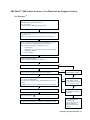
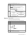
ABI PRISM ® 3100 Genetic Analyzer - User Flowchart for Fragment Analysis
User Flowchart
• Turn on computer.
• OrbixWeb Daemon automatically launches.
• Turn on instrument.
• Launch ABI PRISM¨ 3100 Data Collection Software.
• Present autosampler and place fresh deionized water and 1X GA buffer
in positions 1 to 4.
• Place lower polymer block and anode buffer jar on the instrument.
• Clean the capillary array detection window with ethanol, if necessary.
• Place cleaned array on ABI 3100 using Install Array Wizard.
• The Install Array Wizard takes you through the steps to:
- Install the array
- Fill a 5 mL reserve syringe and a 250 µL array syringe with ABI
3100 POP-4TM polymer
- Remove bubbles
• Open Change Polymer Wizard.
• Log the lot number information in the database.
Fail
• Perform spatial calibration.
Pass
Pass
• Prepare spectral standards and perform spectral calibration.
• Repeat spatial calibration
without filling the capillary.
Fail
• Combine PCR product with Hi-DiTM formamide + internal lane standard
(i.e., GeneScan¨-400HD [ROX]TM).
Pass
• Heat denature for 5 minutes at 95 C, and immediately chill on ice for 2
minutes.
• Remove capillary array and
clean capillary window.
• Inspect window for damage
(i.e., scratches or cracks).
• Add plate septa, tray cover, and plate base, and place on autosampler.
Fail
• Complete plate record and link to plate assignment.
Pass
• Refill capillary with fresh
polymer and rerun spatial
calibration.
• Press the green arrow.
• Review extracted sample files in GeneScan¨ or GeneMapper¨ software.
• If the spatial calibration
continues to be
unsuccessful, refer to the
ABI Prism 3100 User
Manual troubleshooting
chapter.
Performing a Fragment Analysis Run 2-3
Sample Preparation
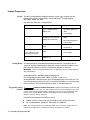
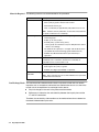
Dye Set The ABI PRISM ® 3100 Data Collection Software version 1.0.1 supports Dye Set
DS-30, DS-31, DS-32, DS-33, DS-02, and the ABI PRISM ® Linkage Mapping
Sets-LD20, -MD10, and -HD5.
Dye Sets, Dye Chemistry, and Applications:
Dye Set
Dye Chemistry
Application Kit
DS-30 (D)
6-FAM™ (blue), HEX™
(green), NED™ (yellow),
ROX™ (red)
Linkage Mapping
DS-31 (D)
DS-32 (F)
DS-33 (G5)
5-dye chemistry for high
throughput genotyping
DS-02 (E5)
New 4-Dye Chemistry:
6-FAM (blue), VIC™ (green),
NED (yellow), ROX (red)
5-FAM™, JOE™, NED,
ROX
6-FAM, VIC, NED, PET™,
LIZ™
dR110, dR6G, dTAMRA™,
dROX™, LIZ
Sets-LD20, -MD10, and
-HD5
Custom Oligos
Linkage Mapping Custom
Oligos
Mouse Mapping Markers
Custom Oligos
AmpFlSTR® products
Stockmarks™
AmpFlSTR® Identifiler™
Custom Oligos
SNAPshot™ Multiplex Kit
Pooling Ratios The fluorescent dyes are detected with different efficiencies. The pooling ratio, or
amount of each dye-labeled product added with respect to the other products in the
pool, should be adjusted to ensure an appropriate detection of all the loci.
IMPORTANT Follow the suggested protocol for each application. See the Linkage Mapping
Sets example below.
Pooling Ratios for the ABI PRISM Linkage Mapping Sets
For Linkage Mapping Sets-LD20, -MD10, and -HD5, a ratio of 1:1:1
(6-FAM:HEX:NED- labeled products) gives acceptable balance across most loci. For
each Linkage Mapping Set panel, pool 1 µL of each PCR product in a microcentrifuge
tube. If necessary, bring the total volume to 10–20 µL with deionized water.
Suggested Loading ! WARNING CHEMICAL HAZARD. Formamide is harmful if absorbed through the skin and
Volumes may cause irritation to the eyes, skin, and respiratory tract. It may cause damage to the central
nervous system and the male and female reproductive systems, and is a possible birth defect
hazard. Please read the MSDS, and follow the handling instructions. Wear appropriate
protective eyewear, clothing, and gloves.
Prepare the formamide:size standard mix using:
1000 µL of Hi-Di™ Formamide (P/N 4311320) or similar quality formamide
50 µL of GS500 ROX, GS500 LIZ, GS120 LIZ, or GS400 HD
Note We recommend that you use Hi-Di Formamide, but if you prefer to prepare your own
formamide, see Appendix A, “Preparing Formamide,” for important information.
2-4 Performing a Fragment Analysis Run
Note Use these ratios of pooled PCR products and size standards as a starting point only.
Optimize these ratios, as necessary, based on your experimental results.
For loading, mix 1µL of pooled PCR products with 10 µL of formamide:size standard
mix.
Denaturing Samples To denature the samples:
Step
1
Action
Heat samples at 95 °C for 3–5 min.
There are several acceptable options for covering samples during denaturation.
2
MicroAmp ® Clear Adhesive Films (P/N 4306311)
MicroAmp Caps (12-Strip) (P/N 801-0534)
MicroAmp Caps (8-Strip) (P/N 801-0535)
MicroAmp Optical 96-well Reaction Plates (P/N N801-0560)
MicroAmp 384-well Reaction Plates (P/N 4305505)
Place immediately on ice for at least 5 min before loading.
Performing a Fragment Analysis Run 2-5
Starting the Data Collection Software
Before You Begin Before starting the ABI PRISM ® Data Collection Software:
Step
1
Action
Ensure the computer and monitor are powered on.
IMPORTANT The computer must be powered on before the instrument.
The default user name is “3100User” and the default password is blank.
2
Ensure the ABI PRISM ® 3100 Genetic Analyzer is powered on and the green status
light is on solid (not flashing).
3
Ensure OrbixWeb Daemon is running by finding its button on the Windows NT
taskbar.
If OrbixWeb Daemon is not running, go to the Start menu, point to Applied
Biosystems, and select OrbixWeb Daemon.
Note To create a shortcut: (a) Navigate to orbixd.exe in the following directory:
D:\dbtools\iona\orbixweb3.2\bin. (b) Right-click the file. (c) Click Create Shortcut.
This creates a shortcut named Shortcut to orbixd.exe. (d) Drag the shortcut to the
desktop.
IMPORTANT OrbixWeb Daemon must be started before the 3100 Data Collection
software can run.
2-6 Performing a Fragment Analysis Run
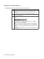
Starting the Data To start the Data Collection software:
Collection Software
Step
1
Action
From the Start menu, point to Applied Biosystems, and select 3100 Data Collection
Software.
Note To create an Applied Biosystems shortcut: (a) Navigate to
3100Collection.bat in the following directory: D:\appliedbio\3100\Bin. (b) Right-click
the file. (c) Click Create Shortcut. This creates a shortcut named Shortcut to 3100
Collection Software. (d) Drag the shortcut to the desktop.
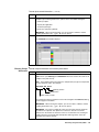
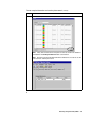
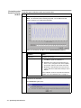
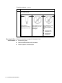
The 3100 Data Collection software opens and the Plate View window displays as
shown below.
Performing a Fragment Analysis Run 2-7
Setting Software Preferences
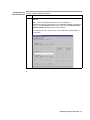
Introduction The Data Collection software preferences are set during instrument installation;
however, you can view or change these preferences in the Setting Preferences dialog
box.
Viewing the Setting To view the Setting Preferences dialog box:
Preferences Dialog
Step
Action
Box
1
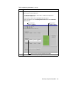
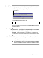
From the View menu, select Preferences or click the Preferences button on the
toolbar.
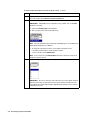
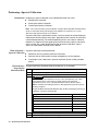
The dialog box has two pages and are described below.
Data Collection Page
2-8 Performing a Fragment Analysis Run
The table below describes the preferences that can be set within this page.
Preference
Description
Instrument Name
This field automatically populates with demo_3100.
You can change it to any name (e.g., the instrument’s serial number).
Note
Avoid spaces between words or any special characters.
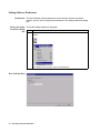
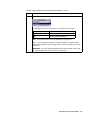
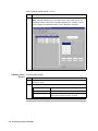
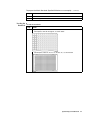
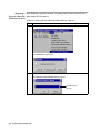
Data Analysis Page
The table below describes the preferences that can be set within this page.
Data Analysis Page Settings:
Preference
Description
AutoAnalysis On
Select AutoAnalysis ON to have samples automatically analyzed by
the analysis software after the run.
Note
time.
BioLIMS
You will still be able to reanalyze your sample data at a later
Use these settings to have data extracted to a BioLIMS database
instead of to sample files on the hard drive.
Performing a Fragment Analysis Run 2-9
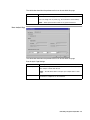
Data Analysis Page Settings:
(continued)
Preference
Description
Sample File Name
Prefix Format
Specify the format for the sample file names by using the drop-down
lists to reorder the identifiers.
Identifier
Origin
Run ID
Generated by the Data Collection software and
contains the capillary number and the date.
Sample Name
Taken from the Plate Editor spreadsheet entry.
See page 2-18.
Well Position
Taken from the sample’s position on the plate
(column letter and row number, e.g., C3).
Plate Name
Taken from the Plate Editor dialog box entry.
Instrument ID
Taken from the Data Collection page preferences
entry.
Array ID
Taken from the Install Capillary Array Wizard
entry.
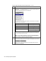
Note In addition to the four identifiers you set with the drop-down
lists, all names are automatically appended with the capillary number
and a file extension. This is also called the Run ID. Therefore, in the
Data Analysis page example shown above, the sample name will be:
Sample Name_Well Position_Capillary Number.fsa
IMPORTANT Using additional filters will create very long file names
which may affect down-stream software analysis.
2-10 Performing a Fragment Analysis Run
Working with Plate Assemblies
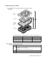
Plate Assembly The plate assembly components are assembled as follows:
Components
Plate
Retainer
Plate Septa
1
2
3
MicroAmp
Reaction
Plate
GR2050
Plate Base
The table below contains ordering information for the plate assembly components.
Component
P/N 384-Well
P/N 96-Well
Plate Retainer
4317240
4317241
Plate Septa
4315934
4315933
MicroAmp Reaction Plate
4305505
N801-0560
Plate Base
4317236
4317237
Preparing a Plate To prepare a plate assembly:
Assembly
Step
1
Action
Secure a clean and dry septa strip on the micro amp optical plate.
IMPORTANT Never use warped plates.
IMPORTANT Ensure the septa strip lies flat on the plate.
2
Place the sample plate into the plate base.
3
Snap the plate retainer onto the plate and plate base.
Performing a Fragment Analysis Run 2-11
To prepare a plate assembly:
Step
4
(continued)
Action
Ensure the plate retainer holes are aligned with the holes in the septa strip.
IMPORTANT Damage to the array tips will occur if the plate retainer and septa
strip holes do not align correctly.
GR2049
The plate retainer holes
must align with the holes in
the septa strip.
2-12 Performing a Fragment Analysis Run
Checking and Refilling Fluids
Adding or Changing Determine whether to add or change the polymer on the instrument before proceeding
Polymer with instrument preparation.
If polymer on the instrument is...
Then...
less than 1 week old, and
Ensure there are no air bubbles, and then proceed
with instrument preparation.
sufficient in quantity to complete
your runsa
greater than 1 week old, or
insufficient in quantity to complete
your runs
Note
To remove any air bubbles, see page 5-4.
Fill the syringes and the upper polymer block with
polymer by following the Change Polymer Wizard. For
instructions, see page 5-12.
! CAUTION CHEMICAL HAZARD. POP
polymers may cause eye, skin, and respiratory tract
irritation. Please read the MSDS for the polymer you
are using, and follow the handling instructions. Wear
appropriate protective eyewear, clothing, and gloves.
Use for research and development purposes only.
a. A run uses 50–80 µL of polymer depending on the length of the array. This is equivalent to 60–100 runs
from one 5-mL syringe. A minimum of 100µL of polymer is required for the instrument to operate.
IMPORTANT Always replace polymer that is older than 1 week.
IMPORTANT Ensure there are no air bubbles in the upper and lower polymer blocks before
proceeding. To remove any air bubbles, see page 5-4.
When to Replace the Replace the 1X Genetic Analyzer buffer in the anode buffer reservoir and the cathode
Buffer buffer reservoir daily, or before each batch of runs.
IMPORTANT Failing to replace buffer may lead to loss of resolution, precision and data
quality.
IMPORTANT Replenishing buffer and placing the plate requires that the autosampler be in the
forward position, with the capillary tips removed from the buffer solution. Do not leave the
autosampler in this position for an extended time because the capillaries can dry out.
Performing a Fragment Analysis Run 2-13
Making Buffer for a To prepare 50 mL of 1X Genetic Analyzer buffer:
Single Run
Step
1
Action
Add 5.0 mL of 10X Genetic Analyzer buffer with EDTA into a graduated cylinder.
! CAUTION CHEMICAL HAZARD. Genetic Analyzer Buffer with EDTA may
cause eye, skin, and respiratory tract irritation. Please read the MSDS, and follow
the handling instructions. Wear appropriate protective eyewear, clothing, and
gloves.
2
Add deionized water to bring the total volume up to 50 mL.
3
Mix well.
Filling the Water IMPORTANT Wear gloves while performing the following procedure, and any other time you
and Cathode Buffer handle the capillary array, glass syringes, septa, or buffer reservoirs.
Reservoirs
To fill the water and cathode buffer reservoirs:
Step
Action
1
Close the instrument doors.
2
Press the Tray button on the outside of the instrument to bring the autosampler to
the forward position.
Tray button
3
Wait until the autosampler has stopped moving, then open the instrument doors.
4
Remove the cathode buffer reservoir and water reservoirs from the instrument.
5
Dispose of remaining fluids and rinse out the reservoirs with deionized water.
Note The waste is very dilute; however, you should follow your company’s waste
disposal practices for appropriate disposal procedures.
6
Rinse the cathode reservoir with 1X Genetic Analyzer buffer, and fill to the line with
1X Genetic Analyzer buffer (about 16 mL).
7
Fill the water reservoirs to the line with quality deionized water (about 16 mL).
2-14 Performing a Fragment Analysis Run
To fill the water and cathode buffer reservoirs:
Step
8
(continued)
Action
Place a clean septa strip on each reservoir, and dry the outside of the reservoirs
using a lint-free wipe.
Note
We suggest labeling the reservoirs to prevent mixing them up.
! CAUTION Be sure that the septa fit snugly and flush on the tops of the
reservoirs in order to prevent damaging the capillary tips.
Septa is lying flat on the reservoir
Fill line
9
Place the reservoirs into position on the autosampler as shown below.
Water reservoir
(rinse)
4
2
1
Water reservoir
(waste)
Cathode reservoir
(1X Genetic Analyzer buffer)
Water reservoir
3
Filling the Anode Change the anode buffer:
Buffer Reservoir Before each batch of runs, or at least every 24 hours
Every time you fill the polymer block with new polymer
To fill the anode buffer reservoir to the fill line with 1X Genetic Analyzer buffer:
Step
Action
1
Remove the anode buffer reservoir by firmly pulling down and twisting slowly.
2
Discard the used buffer appropriately.
3
Clean and rinse the reservoir with deionized water, and then rinse with buffer.
4
Fill the reservoir to the fill line with fresh 1X Genetic Analyzer buffer (about 9 mL).
Fill line
5
Put the anode buffer reservoir on the instrument.
Note
The meniscus should line up with the fill line.
Performing a Fragment Analysis Run 2-15
To fill the anode buffer reservoir to the fill line with 1X Genetic Analyzer
Step
6
Action
If the reservoir fills with fluid, repeat this procedure to discard and replace the
Genetic Analyzer buffer.
Note
2-16 Performing a Fragment Analysis Run
The reservoir could fill during bubble clearing.
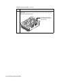
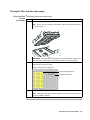
Placing the Plate onto the Autosampler
Placing the Plate To place the plate onto the autosampler:
onto the
Step
Action
Autosampler
1
Place the plate assembly on the autosampler as shown below.
GR2051
Note There is only one orientation for the plate, with the notched end of the plate
base away from you.
IMPORTANT Ensure the plate assembly fits flat in the autosampler. Failure to do
so may allow the capillary tips to lift the plate assembly off of the autosampler.
2
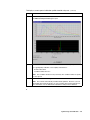
When the plate is correctly positioned, the plate position indicator on the Plate View
page changes from gray to yellow.
Check to ensure this has happened.
Plate placed in position A
No plate in position B
3
Close the instrument doors.
Note Closing the doors returns the autosampler to the home position, placing the
tips of the capillaries in buffer.
Performing a Fragment Analysis Run 2-17
Creating a Plate Record
About Plate Records Plate records are data tables in the instrument database that store information about
the plates and the samples they contain.
Note A plate record is similar to a sample sheet or an injection list that you may have used
with other ABI PRISM instruments.
Using the Plate Follow the two procedures below to create a plate record with the Plate Editor.
Editor to Create a
See the ABI PRISM 3100 Genetic Analyzer User’s Manual (P/N 4315834) for other
Plate Record ways to create plate records and for information about importing and exporting plate
records.
Entering Plate Note You cannot create a plate record while a run is in progress.
Record Information
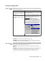
To enter plate record information:
Step
1
Action
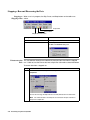
Click the Plate View tab on the 3100 Data Collection Software window to go to the
Plate View page.
Plate View tab
2
In the Plate View page, click New. Or, double-click the Plate Editor button on the
toolbar.
The Plate Editor dialog box opens.
2-18 Performing a Fragment Analysis Run
To enter plate record information:
Step
3
(continued)
Action
Use the Plate Editor dialog box to name your plate and to specify the application
and plate type. Entering comments is optional. In the Plate Editor dialog box:
a. Name your plate.
b. Specify the application.
c. Select the plate type.
d. Enter any comments (optional).
IMPORTANT When naming the plate, you can use letters, numbers, and the
following punctuation only: -_(){}#.+. Do not use spaces.
4
When done, click Finish.
The Plate Editor spreadsheet displays.
Entering Sample To enter sample information and save the plate record:
Information
Step
1
Action
In the Plate Editor spreadsheet, type the names of all the samples in the Sample
Name column. (Use Edit/Copy and Edit/Fill Down whenever a field is the same for all
samples in the plate record.)
Note In the default naming convention, the sample name you type is incorporated
into the sample file name. For example:
MySample_A01_01.fsa
Capillary position
Well position
Sample name you type
\
The sample file naming convention used can be changed in the Preferences dialog
box. See page 2-9 for details.
IMPORTANT When naming the samples, you can use letters, numbers, and the
following punctuation only: -_(){}#.+. Do not use spaces.
IMPORTANT Be sure that sample file names are not longer than 55 characters.
An underscore separates each preference selected, so be sure to count the
underscore in the number of characters. There is no automatic error checking for
sample names that exceed this limit. Sample files with long names cannot be
opened by the analysis software.
Performing a Fragment Analysis Run 2-19
To enter sample information and save the plate record:
Step
2
(continued)
Action
Optional
For each sample, enter Color Info and Color Comment text.
3
Enter a BioLIMS project.
IMPORTANT A BioLIMS project is required for every sample, even if a BioLIMS
database is not used.
a. Click in the BioLIMS Project cell for Well A1.
b. Select a project name from the drop-down list.
Note For more information about setting up a BioLIMS project, see the ABI PRISM
3100 Genetic Analyzer User’s Manual.
c. To assign the same project name to each sample in the plate record:
– Click the column header to select the whole column.
– Press CTRL+D or select Edit/Fill Down.
Note Press CTRL+D or select Edit/Fill Down whenever a field is the same for all
samples in the plate record.
4
For each sample, select the appropriate Dye Set from the drop-down list.
IMPORTANT Be sure to select the correct dye set for your run(s). Data collected
with the incorrect dye set selected cannot be saved, and the runs will have to be
repeated because multicomponenting is applied during collection. This is called a
chemometric process.
2-20 Performing a Fragment Analysis Run
To enter sample information and save the plate record:
Step
5
(continued)
Action
For each sample, select the appropriate Run Module from the drop-down list.
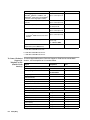
The table below shows the run module to select based on your run type.
Analysis Type
Run Module
GeneScan
GeneScan36_POP4DefaultModule
SNP
SNP36_POP4DefaultModule
Note
If you need to view or edit a run module file, see page 2-29.
Note If you select different modules for different samples, the samples will be
automatically grouped so that all samples with the same run module are run at the
same time.
IMPORTANT Runs are scheduled alphanumerically by run module name, not by
the order indicated in the plate record, nor by sample name.
Performing a Fragment Analysis Run 2-21
To enter sample information and save the plate record:
Step
6
(continued)
Action
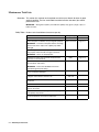
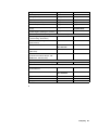
For each sample, select the appropriate Analysis Module from the drop-down list.
IMPORTANT The AutoAnalysis ON preference must be selected if analysis is to
take place automatically after the run (see page 2-9).
The table below shows which analysis module to select based on the number of
fragments in your size standard.
If using size standard...
Select this analysis module...
GS120
GS120Analysis.gsp
GS400HD
GS400HDAnalysis.gsp
GS350
GS350Analysis.gsp
GS500
GS500Analysis.gsp
GS500
GS400CubicAnalysis.gspa
GS400Ord2Analysis.gspa
a. These modules are for advanced users with specific sizing needs. See the ABI PRISM
GeneScan Analysis Software User Guide.
Note You can examine the settings for each of these files using GeneScan
Analysis software. The meanings of the settings are described in the ABI PRISM
GeneScan Analysis Software User Guide (P/N 4308923).
7
If you want to run the same sample again, select a second run module and a
second analysis module. You can run a sample in a linked plate up to five times.
Samples will be automatically grouped so that all samples with the same run
module are run sequentially.
2-22 Performing a Fragment Analysis Run
To enter sample information and save the plate record:
Step
8
(continued)
Action
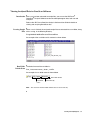
Make sure the plate record is correct, and then click OK.
Note It may take a moment for the new plate record to be saved to the database
and added to the Pending Plate Records table as shown below.
Note The plate record must be deleted from the database first, in order to use the
same name for another plate record.
Performing a Fragment Analysis Run 2-23
Linking and Unlinking a Plate
Introduction The procedure below describes how to link a plate on the autosampler to the plate
record you have created. This must be done before a plate can be run.
IMPORTANT A plate can be linked even if there are no run modules selected for its samples.
In this case, there is no error message and runs for samples in the plate will not be scheduled.
Linking a Plate to a To link a plate to a plate record:
Plate Record
Step
1
Action
Click the Plate View tab on the 3100 Data Collection Software window to go to the
Plate View page.
Plate View tab
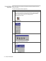
2
On the Plate View page:
a. In the Pending Plate Records table, click the plate record for the plate you are
linking.
b. Click the plate position indicator that corresponds to the plate you are linking.
Click the plate record
Click anywhere on the plate position indicator
2-24 Performing a Fragment Analysis Run
To link a plate to a plate record:
Step
3
(continued)
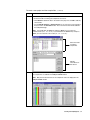
Action
Verify that the plate has been linked.
Once the plate has been linked, the:
The Run Instrument button on the toolbar is enabled, meaning that the
instrument is ready to run.
Plate position indicator for the linked plate becomes green.
Plate record moves from the Pending Plate Records table to the Linked Plate
Records table.
Run Instrument
button is enabled
Plate position
indicator is green
Plate record is in the Linked Plate Records table
4
Repeat steps 1–3 to link a second plate, if applicable.
Performing a Fragment Analysis Run 2-25
To link a plate to a plate record:
Step
5
(continued)
Action
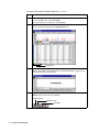
Click the Run View tab to view the run schedule.
Note Although individual runs can be deleted, the order in which the runs are
scheduled cannot be altered. Run scheduling depends upon a number of factors;
see the ABI PRISM 3100 Genetic Analyzer User’s Manual for information.
Unlinking a Plate To unlink a plate record:
Record
Step
Action
1
In the Linked Plate Records table of the Plate View page, select the plate record that
you want to unlink.
2
Click Unlink.
2-26 Performing a Fragment Analysis Run
If the plate record is...
Then the plate record will...
completed
go to the Processed Plate Records.
not completed
return to the Pending Plate Records table, and the
plate position indicator will return to yellow.
Starting and Monitoring the Run
Starting a Run To start a run:
Step
1
Action
Click the green Run Instrument button to begin the scheduled runs.
Run Instrument button
A run using GeneScan_POP4DefaultModule takes approximately 45 min.
Monitoring a Run To monitor a run:
Step
Action
1
Click the Status View tab to monitor the status of the instrument during the run.
2
During the run, you can view the data using the Array View and Capillary View
pages.
IMPORTANT Always exit from the Array View and the Capillary View windows. Do
not leave these windows open for extended periods during a run because
unrecoverable screen update problems will occur. Leave the Status View window
open.
For more information about the Array and Capillary views, see “Viewing Raw Data”
on page 3-2.
Performing a Fragment Analysis Run 2-27
Stopping a Run and Recovering the Data
Stopping or When a run is in progress, the Skip, Pause, and Stop buttons on the toolbar are
Skipping a Run visible.
Stop button
Pause button
Skip to Next Run button
To stop the current run and…
Click…
continue the other scheduled runs
the Skip button.
stop the other scheduled runs
a. the Stop button.
b. Now in the Question dialog box.
If Autoextraction The auto extractor should have automatically extracted your data from the stopped
Fails run. If it did not, use the Extract data into sample files commands as described below.
To recover data from a stopped run:
Step
1
Action
From the Instrument menu, point to Data Acquisition and select Extract data into
sample files.
Look for the message “Sample Files Successfully Extracted” in the Status bar.
Note The extracted data is unanalyzed. Use GeneScan Analysis software to
analyze the sample files.
2-28 Performing a Fragment Analysis Run
Viewing, Editing, or Creating a Run Module
Introduction The run module specifies information about how the sample is run (e.g., the duration
of the run, the run temperature, and the injection time).
Viewing a Run To view a run module:
Module
Step
1
Action
Click the Module Editor button on the toolbar.
The Module Editor dialog box opens.
2
In the Modules group box, click the GeneScan tab.
3
To view the parameters for a particular module, select the name of the module from
the list. All the parameters for the run module are displayed.
Performing a Fragment Analysis Run 2-29
Editing or Creating To edit an existing run module or to create a new run module:
a Run Module
Step
1
Action
Click the Module Editor button on the toolbar.
The Module Editor dialog box opens.
2
Select a run module to use as a template.
3
Edit the parameter values that you want to change.
IMPORTANT Only whole numbers are accepted.
IMPORTANT Be sure that all values are red. Values in black are not saved.
4
Click Save As to create a new run module.
Enter a unique descriptive name and click OK.
Note Save cannot be applied to default run modules. Modules are saved in the
database and are accessed through the module editor for viewing.
5
When you are finished, click the Close button (
2-30 Performing a Fragment Analysis Run
) to exit the Module Editor.
About Viewing and Editing Modules for GeneScan Analysis
Introduction The analysis module specifies how the raw data is autoanalyzed at the end of the run
(e.g., analysis range and size standard parameters).
Viewing and Editing To view or edit a GeneScan analysis module (.gsp file):
Modules for
Step
Action
GeneScan Analysis
1
Start the GeneScan Analysis software.
You may have a program icon for the GeneScan Analysis software on the Start
menu or a shortcut icon on your desktop. If not, you can find the application
(GeneScan.exe) in the following directory:
D:\appliedbio\GeneScan\Bin
2
From the File menu, select Open.
3
Select the Analysis Parameters icon.
4
Select the analysis module you want to view or edit. The analysis modules are
stored in the following directory:
D:\appliedbio\Shared\Analysis\Sizecaller\Params
5
Click Open.
This opens the analysis module.
Performing a Fragment Analysis Run 2-31
To view or edit a GeneScan analysis module (.gsp file):
Step
6
(continued)
Action
If you want, you can make changes to the analysis module. For more information
about the parameters, see the ABI PRISM GeneScan Analysis Software User
Guide.
7
If you have made changes to
the analysis module and you
want to...
save the changes as a new
analysis module
Then...
we recommend that you select Save As from
the File menu, assign a new name, and click OK.
Note The analysis modules must be stored
in the following folder:
D:\appliedbio\Shared\Analysis\
Sizecaller\Params
discard the changes
2-32 Performing a Fragment Analysis Run
click the Close button to close the window.
Viewing and Analyzing
Data
3
3
Overview
In This Chapter This chapter includes the following topics:
Topic
See Page
Viewing Raw Data from a Completed Run in the Data Collection Software
3-2
Viewing Analyzed Data in GeneScan Software
3-5
Analyzing or Reanalyzing Data in GeneScan Software
3-12
Note This chapter assumes that run data has been extracted into sample files. If you are
using the ABI PRISM ® 3100 Genetic Analyzer in conjunction with the BioLIMS® database
system, you may want to refer to the ABI PRISM GeneScan Analysis Software User Guide
(P/N 4308923) for information about accessing the database using the analysis program.
Viewing and Analyzing Data 3-1
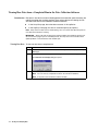
Viewing Raw Data from a Completed Run in the Data Collection Software
Introduction Raw data is data that has been multicomponented (corrected for spectral overlap) but
mobility correction has not been applied. There are two formats for viewing the raw
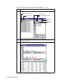
data within the ABI PRISM ® 3100 Data Collection Software.
In the Array View page, the review data accesses all 16 capillaries.
In the Capillary View page, the data is accessed capillary-by-capillary.
Note Only current run data can be viewed during a run. You cannot view data from previous
runs while the instrument is running.
IMPORTANT Always exit from the Array View and the Capillary View windows. During a run,
do not leave these pages open for extended periods. This may cause unrecoverable screen
update problems. Leave the Status View window open.
Viewing Raw Data To view raw data from a completed run:
Step
Action
1
In the 3100 Data Collection software, click the Array View tab to display the Array
View page.
2
From the Instrument menu, point to Data Acquisition, and choose Display Run Data.
The Select the run to display dialog box opens.
3
3-2 Viewing and Analyzing Data
From the drop-down list, select the run that you want to display and click OK.
Note
You can view any completed run data in the instrument database.
Note
It may take a few moments to retrieve the data.
To view raw data from a completed run:
Step
4
(continued)
Action
Use the scroll features on the Array View page to view the data.
IMPORTANT Always exit from the Array View and the Capillary View windows.
During a run, do not leave these pages open for extended periods. This may cause
unrecoverable screen update problems. Leave the Status View window open.
Capillary/Color
Data display
Selected capillary to be displayed
in the center plot
Raw electropherogram
display for selected
capillary
Use this scroll box to
view data
Viewing and Analyzing Data 3-3
To view raw data from a completed run:
Step
5
(continued)
Action
Alternatively, to view electropherogram data from several capillaries at once, click
the Capillary View tab to display the Capillary View page.
IMPORTANT Always exit from the Array View and the Capillary View windows.
During a run, do not leave these pages open for extended periods. This may cause
unrecoverable screen update problems. Leave the Status View window open.
Select check
boxes of the
capillaries to
be displayed
3-4 Viewing and Analyzing Data
Viewing Analyzed Data in GeneScan Software
Introduction After a run has been extracted to sample files, you can use the ABI PRISM ®
GeneScan® Analysis Software to view the electropherogram data, both raw and
analyzed.
Refer to the ABI PRISM GeneScan Analysis Software User Guide for details on
viewing and analyzing GeneScan data.
Locating Sample When a run is finished, the analyzed sample files are extracted into a run folder, along
Files with a run log, in the following directory:
D:\appliedbio\3100\DataExtractor\ExtractedRuns
An example of the run folder and its contents is shown below.
Run Folder The default name of the run folder is:
Default Name
Run_<Instrument name>_<date>_<runID>
An example of a run folder name is shown below.
Run Index number
Instrument
name
Note
Year-month-day
The counter for the Run Index number does not reset each day.
Viewing and Analyzing Data 3-5
Viewing Individual Note All the features of the software are described in the ABI PRISM GeneScan Analysis
Sample Files Software User Guide.
To create a new project and view sample files:
Step
1
Action
Start the GeneScan Analysis software.
You may have a program icon for the GeneScan Analysis software on the Start
menu or a shortcut icon on your desktop. If not, you can find the GeneScan
Analysis program (GeneScan.exe) in the following directory:
D:\appliedbio\Genescan\Bin
2
From the File menu, select New.
3
Click the Project icon to create a new project.
An untitled Analysis Control window opens.
4
3-6 Viewing and Analyzing Data
From the Project menu, select Add Sample Files to open the Add Sample Files
dialog box.
To create a new project and view sample files:
Step
5
(continued)
Action
In the Add Sample Files dialog box:
a. Select the folder containing the sample files of interest.
b. Click Add All to add all the files in the folder to the project list, or Add to add only
selected files.
c. Use the Add All, Remove, or Remove All buttons as necessary to list all the files
that you want in the File Name list box. These are the files that will be added to
the Sample Manager.
Note If you hold down the SHIFT key and press ENTER, you can select all
continuous files (i.e.,1, 2, 3, 4, etc.). If you hold down the CONTROL key and press
ENTER, you can select files out of order (i.e.,1, 3, 7, 12, etc.).
Select the folder
containing
sample files
Add the
selected files to
this list box
6
Click Finish to close the Add Sample Files dialog box.
The sample files are added to the Analysis Control window.
Note
Only the first 20 characters of the sample file name are displayed in the
Analysis Control window.
Viewing and Analyzing Data 3-7
To create a new project and view sample files:
Step
7
(continued)
Action
Save the project:
a. From the File menu, select Save Project.
b. Enter a file name for the project, and click Save.
8
Double-click the sample file name in the Analysis Control window to view a sample
file. This automatically displays the Sample Results view.
View buttons
9
10
If the window looks like the one below, the sample files have not been analyzed.
Refer to “Analyzing or Reanalyzing Data in GeneScan Software” on page 3-12 for
information on how to analyze data.
If your window does not look like either step 8 or step 9 of above, click the Sample
Results button in the corner of the window.
Sample Results
Sample File Info
Raw Data
3-8 Viewing and Analyzing Data
To create a new project and view sample files:
Step
11
(continued)
Action
Use the Magnifying tool to change the scale of the plot.
a. Click on the tool to select it. (
).
b. Click on the plot to zoom in or ALT-click to zoom out.
Alternatively, use the commands on the View menu to adjust the plot scale.
12
To identify a peak, click it.
That peak’s row in the GeneScan table is highlighted.
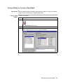
Viewing Multiple The procedure below introduces you to the Results Control window. A complete
Files description of the Results Control window is provided in the ABI PRISM GeneScan
Analysis Software User Guide.
To view multiple data sets using the Results Control window:
Step
Action
1
If not already open, start the GeneScan Analysis software.
2
Create a project as described in steps 2 to 6, beginning on page 3-6. Or open an
existing project by selecting Open from the File menu.
3
From the Windows menu, select Results Control.
4
From the # of Panels menu, select 8.
Viewing and Analyzing Data 3-9
To view multiple data sets using the Results Control window:
Step
5
(continued)
Action
Click on the project sample number to select all colors for that sample.
Project sample number
Dye color fields
Panel number
Electropherogram button
Table button
Number of
panels
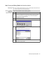
6
Configure the next panel by clicking the panel number button for panel 2 and
repeating step 5 above.
7
Click the display button to display the panels and table.
3-10 Viewing and Analyzing Data
To view multiple data sets using the Results Control window:
Step
(continued)
Action
8
To print the display, from the File menu, choose Print.
9
Use the Clear Panel or Clear All buttons on the Results Control window to clear
panels.
Viewing and Analyzing Data 3-11
Analyzing or Reanalyzing Data in GeneScan Software
Introduction Note For more information about analyzing data using GeneScan Analysis software, see the
ABI PRISM GeneScan Analysis Software User Guide.
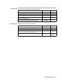
When to Analyze Data with GeneScan Analysis Software
The sample file will not contain analyzed data if you did not specify an analysis
module in the plate record.
If the sample file does not contain analyzed data, you need to analyze the file as
described in the procedure below.
When to Reanalyze Data with GeneScan Analysis Software
Reanalyze the sample files using GeneScan Analysis software when you:
Chose the wrong analysis module file in the plate record
Want to see the effect of changing analysis parameters on your data
Analyzing or To analyze or reanalyze sample files:
Reanalyzing
Step
Action
Sample Files
1
If not already open, start the GeneScan Analysis software.
2
Create a project as described in steps 2 to 6, beginning on page 3-6. Or open an
existing project by selecting Open from the File menu.
3
CTRL-click the dye color field to set the size standard color.
The diamond (lozenge) in the red color field indicates that the red size standard will
be used for the analysis.
4
3-12 Viewing and Analyzing Data
From the Size Standard pop-up list, select the correct size standard (.szs) file for the
sample files in the table.
To analyze or reanalyze sample files:
Step
(continued)
Action
5
From the Parameters pop-up list, select the correct analysis parameters (.gsp) file
for the sample files in the table.
6
To review or edit the analysis parameters, double-click the parameters file name.
The Analysis Parameters dialog box opens. Suggested values for parameters are
shown below. Refer to the ABI PRISM GeneScan Analysis Software User Guide for
more information about analysis parameters.
7
If you make changes to the analysis parameters:
a. Select Save As from the File menu.
b. Choose a new name for the analysis parameters (.gsp) file.
Viewing and Analyzing Data 3-13
To analyze or reanalyze sample files:
Step
8
(continued)
Action
Select all dye lanes by clicking in the upper-left corner of the dye color fields bar.
Click here to select all lanes and all colors
Before clicking
9
After clicking
Click the Analyze button.
The analyzed data is automatically saved to the sample files. If analyzed data
already existed in the sample file, it is overwritten.
As the lanes are analyzed, they are deselected in the dye color fields.
3-14 Viewing and Analyzing Data
Spatial and Spectral
Calibrations
4
4
Overview
In This Chapter This chapter includes the following topics:
Topic
See Page
Performing a Spatial Calibration
4-2
Performing a Spectral Calibration
4-6
Spatial and Spectral Calibrations 4-1
Performing a Spatial Calibration
When to Do a A spatial calibration must be performed each time after you:
Spatial Calibration Install or replace a capillary array
Temporarily remove the capillary array from the detection block
What a Spatial A spatial calibration provides information about the position of the fluorescence from
Calibration Tells each capillary on the CCD camera. It does not provide information about the
You performance of the capillaries.
Performing a Spatial To perform a spatial calibration:
Calibration
Step
1
Action
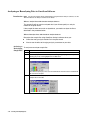
From the Tools menu, select Perform Spatial Calibration.
The Perform Spatial Calibration dialog box opens.
2
Select the Fill capillaries check box if the:
Capillaries have no polymer (i.e., a new capillary array), or
Polymer in the capillaries has been used in a run
Note You do not need to fill the capillaries each time you perform a spatial
calibration.
3
Click Start.
The calibration takes approximately:
2 min without filling the capillaries
6 min with filling the capillaries
4-2 Spatial and Spectral Calibrations
To perform a spatial calibration:
Step
4
(continued)
Action
If the calibration...
Then...
succeeded
the following dialog box opens:
a. Click Details to view the Spatial Calibration Profile
window.
b. Continue on to “Viewing Successful Results and
Saving the Data” below.
failed
an error message box opens, providing some
information about the reason for the failure.
a. Click Details to view the Spatial Calibration Profile
window.
b. Do one of the following:
– Click Cancel, and then click Start to repeat the
calibration.
– Take corrective action as outlined on page 4-5.
Spatial and Spectral Calibrations 4-3
Viewing Successful To view the spatial calibration results and save the data:
Results and Saving
Step
Action
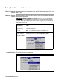
the Data
1
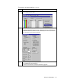
Evaluate the spatial calibration profile.
Note For information about evaluating the profile, see the ABI PRISM 3100
Genetic Analyzer User’s Manual (P/N 4315834).
When you are finished, click OK to close the Spatial Calibration Profile box.
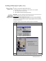
2
If the spatial calibration
profile is...
Then...
satisfactory
Continue on to step 3.
unsatisfactory
a. Click Cancel to close the Details box, and then
click Start to repeat the calibration, or
b. Reposition one or more of the red crosses. To
move a cross, change the value in the Capillary
Position box, and then click outside of that box.
c. Override the data with data from a previous run,
see the ABI PRISM 3100 Genetic Analyzer User’s
Manual.
If the calibration continues to provide unsatisfactory
results, see “If the Calibration Fails” on page 4-5.
3
Click OK to close the Perform Spatial Calibration window and to send the passing
calibration to the instrument.
The Question dialog box opens.
4-4 Spatial and Spectral Calibrations
To view the spatial calibration results and save the data:
Step
4
(continued)
Action
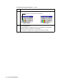
To...
Then...
save this calibration data to the
Data Collection software database
Click Yes.
delete this data and use data from a
previous run
a. Click No.
b. Override the current spatial calibration
map.
If the Calibration If the calibration failed, or if you do not like the appearance of the passed calibration
Fails profile, try one or more of the following corrective actions.
Repeat the calibration.
Fill the capillaries with polymer, and then repeat the calibration.
Clean the detection cell, and then repeat the calibration.
Reposition the array window in the detection cell, and then repeat the calibration.
Spatial and Spectral Calibrations 4-5
Performing a Spectral Calibration
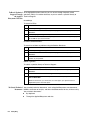
Introduction Performing a spectral calibration can be divided into three main tasks:
Setting up the standards
Starting the spectral calibration
Checking the spectral calibration
Note This section describes spectral calibration using the Matrix Standard Set DS-30 of Dye
Set D. For information about performing spectral calibration for another dye set, see the
ABI PRISM 3100 Genetic Analyzer User’s Manual .
A spectral calibration is performed to create a matrix to correct for the overlapping of
fluorescence emission spectra of the dyes. Application of this matrix to the raw data is
called multicomponenting. The multicomponenting occurs as the data is collected;
therefore it is important to make good quality matrices for each capillary and ensure
each is unique. For a more detailed explanation of spectral calibration, see the
ABI PRISM 3100 Genetic Analyzer User’s Manual.
When to Perform a A spectral calibration must be performed:
Spectral Calibration Whenever you use a new dye set on the instrument
After the laser or CCD camera has been realigned by a service engineer
If you begin to see a decrease in spectral separation (pull-up and/or pull-down
peaks)
Instructions for To prepare the Matrix Standards (Dye Set D Matrices as an example).
Preparing the
Action
Matrix Standards Step
1
Thaw and mix thoroughly the four DS-30 (P/N 4316100) matrix standard tubes.
2
Spin the tubes briefly in a microcentrifuge.
3
! WARNING CHEMICAL HAZARD. Formamide is harmful if absorbed through
the skin and may cause irritation to the eyes, skin, and respiratory tract. It may
cause damage to the central nervous system and the male and female
reproductive systems, and is a possible birth defect hazard. Please read the
MSDS, and follow the handling instructions. Wear appropriate protective eyewear,
clothing, and gloves.
Prepare the Matrix Standard Set DS-30 for Dye Set D by combining the following in
a labeled 1.5-mL microcentrifuge tube:
Reagent
6FAM
2.5
HEX
2.5
NED
2.5
ROX
2.5
Hi-DiTM Formamide (P/N 4311320)
190
Final Volume
200
4
Vortex thoroughly.
5
Spin the mixture briefly in a microcentrifuge.
4-6 Spatial and Spectral Calibrations
Volume (µL)
To prepare the Matrix Standards (Dye Set D Matrices as an example).
Step
(continued)
Action
6
Heat the standard tube at 95 °C for 5 min to denature the DNA.
7
Immediately place the tubes on ice for 2 min.
Loading the To load the standards:
Standards
Step
1
Action
Dispense 10 µL of the denatured matrix standard into a:
96-well plate, wells A1 through H2, as shown below
384-well plate, wells A1, A3, C1, C3, E1, E3, etc., as shown below
Spatial and Spectral Calibrations 4-7
To load the standards:
Step
2
(continued)
Action
Centrifuge the plate so that the each standard is positioned at the bottom of its well.
Your samples should:
Look like this...
Not look like this...
Not look like this...
The sample is
positioned correctly in
the bottom of the well.
The sample lies on the
side wall because the
plate was not
centrifuged.
An air bubble lies at the
bottom of the well
because the plate was
not:
Centrifuged with
enough force, or
Centrifuged for
enough time
Preparing the Plate Follow the instructions on pages 2-11 through 2-17 to:
and Instrument Assemble the plates
Check and refill the fluids on the instrument
Place the plate on the autosampler
4-8 Spatial and Spectral Calibrations
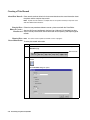
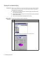
Creating a Plate To create a plate record for the denatured matrix standards:
Record
Step
1
Action
On the Plate View page of the Data Collection software, click New.
The Plate Editor dialog box opens.
2
In the Plate Editor dialog box:
a. Name the plate.
b. Select Spectral Calibration.
c. Make sure that the appropriate plate size is selected.
d. Click Finish.
The Plate Editor spreadsheet opens.
3
Complete the Plate Editor spreadsheet for the wells you have loaded:
a. Type a name for the samples.
b. Select Dye Set D.
c. Select the run module Spect36_POP4DefaultModule.
d. Select the spectral parameter MtxStd{GeneScan-SetD}.par.
e. Click OK.
IMPORTANT Make sure the correct spectral parameter file has been selected for
the type of dyes you are running. Selecting the incorrect parameter file will cause
the spectral calibration to fail.
This creates a plate record for the calibration run in the database. After a few
seconds, the entry for the plate record appears in the Pending Plate Records table
of the Plate Setup page.
Spatial and Spectral Calibrations 4-9
Linking the Plate To link the plate record to the plate:
Step
Action
1
In the Pending Plate Records table, select the plate record that you just created.
2
Click the plate graphic that corresponds to the plate on the autosampler.
Note
When a plate is linked, the:
– Plate graphic changes from yellow to green.
– Plate record moves from the Pending Plate Records table to the Linked Plate
Records table. (This may take up to 30 sec.)
– The Run Instrument button on the toolbar is enabled, meaning that the
instrument is ready to run.
Starting the To start the calibration:
Calibration
Step
Action
1
To review the run schedule before beginning the run, click the Run View tab.
2
Click the Run Instrument button on the toolbar to begin the run.
The spectral calibration run takes approximately 30 min.
Run Times The table below lists the spectral calibration run times.
Application
Capillary Array Length
(cm)
Approximate Run Time
(min)
Fragment analysis
36
30
DNA sequencing
36
40
50
65
4-10 Spatial and Spectral Calibrations
Spectral Calibration At the end of the run, while the data is being analyzed, the Spectral Calibration Result
Result Box dialog box opens to indicate which capillaries have passed and which have failed. The
example below for Dye Set D shows failed capillaries, which are represented by “x”
and passed capillaries which are represented by “.” dots.
Passed capillary (.)
Failed capillary (X)
To acknowledge the completed calibration run:
Step
1
Action
In the Spectral Calibration Result box, click OK.
IMPORTANT Review and evaluate the spectral calibration profile for each capillary, even if the
Spectral Calibration Results box indicated that they all passed. See the ABI PRISM 3100 Genetic
Analyzer User’s Manual.
When a Capillary If a capillary fails, it is automatically assigned the spectral profile of its nearest passing
Fails capillary to the left. If there are no passing capillaries to the left, it will be assigned the
profile of the nearest passing capillary to the right. These capillaries are marked
yellow instead of green in the Array View (e.g., page 3-3).
IMPORTANT For applications where pull-ups and pull-downs will cause critical errors, we
recommend that you repeat the spectral calibration and use a unique spectral for each capillary.
When the If the spectral calibration failed, or if you do not like the appearance of the passed
Calibration Fails calibration, try one or more of the following:
Verify that the correct parameter file and run module were selected. If not, correct,
and then repeat the run.
Verify the freshness of the reagents used.
Verify that all peaks were detected. A slow running system can result in the blue
peak being partially or totally cut off. Add time to the run, or change the reagents if
they are suspect, and then repeat the run.
Spatial and Spectral Calibrations 4-11
Examining a After completing a spectral calibration, it is good practice to check the quality of the
Spectral Calibration spectral data for each capillary.
Profile for Dye Set D
To display a current spectral calibration profile stored for a dye set:
Step
1
Action
From the Tools menu, select Display Spectral Calibration.
The Question dialog box opens.
2
Click Dye set.
The Select the source to display dialog box opens.
Drop-down list of
dye sets
4-12 Spatial and Spectral Calibrations
To display a current spectral calibration profile stored for a dye set:
Step
3
(continued)
Action
From the drop-down list, select Dye Set D and click OK.
The Matrices for dye set D dialog box opens.
4
Use the arrow buttons or the slider to review the data for each capillary.
For a good-quality calibration, each capillary should have a:
Q value above 0.95
Condition number from 4–7
Note This condition number is for dye set D only. The condition number is specific
for each dye set.
5
Click Cancel to close the dialog box.
Note The software automatically overrides failed capillaries. However, if you are
dissatisfied with a particular profile, you can override it with a preferred profile. For
more information, see the ABI PRISM 3100 Genetic Analyzer User’s Manual.
Spatial and Spectral Calibrations 4-13
Maintaining the
Instrument
5
5
Overview
In This Chapter This chapter contains information about the things you should do to maintain your
ABI PRISM ® 3100 Genetic Analyzer.
Topic
See Page
Maintenance Task Lists
5-2
Removing Air Bubbles from the Upper Polymer Block
5-4
Checking the Available Disk Space
5-6
Cleaning and Inspecting Syringes
5-8
Removing the Polymer Blocks
5-10
Cleaning the Polymer Blocks
5-11
Putting Fresh Polymer on the Instrument
5-12
Before Installing a Previously Used Capillary Array
5-14
Installing and Removing the Capillary Array
5-15
Storing a Capillary Array
5-16
Shutting Down the Instrument
5-17
Maintaining the Instrument 5-1
Maintenance Task Lists
Overview This section lists common tasks required to maintain your Genetic Analyzer in good
working condition. The lists are divided into tables based on how often you should
perform each task.
IMPORTANT Wear gloves anytime you handle the capillary array, glass syringes, septa, or
buffer reservoirs.
Daily Tasks Perform tasks listed below at least once per day.
Maintenance Task
Frequency
See...
Ensure the reservoir septa are firmly seated and flat.
Before each run
—
Ensure the plate assemblies were put together properly.
Before each run
page 2-11
Before each run
—
Replenish the water and 1X Genetic Analyzer buffer
reservoirs on the instrument.
Daily
page 2-13
Check for bubbles in the polymer block and polymer
block channels and remove.
Daily
page 5-4
Daily
—
Daily or before
each run
—
Check the polymer block to ensure it fits securely on the
instrument.
Daily
—
Clean the instrument surfaces.
Daily
—
Check for dried polymer around the polymer block and
clean as necessary.
Daily
—
Check for leaks inside the syringe around the plunger
and capillary array ferrule.
Daily
—
Check database space. Delete plate records from the
instrument database and archive sample files.
Daily
page 5-6
IMPORTANT The holes in the plate retainer must align
with the holes in the septa or the capillary tips will be
damaged.
Ensure the plate assemblies are positioned on the plate
deck properly. Plates should sit snugly on the deck.
IMPORTANT Never use warped plates.
IMPORTANT Ensure that all bubbles have been
pushed through the peek tubing.
Check the loading-end header to ensure the capillary tips
are not crushed or damaged.
Check the level of polymer in the polymer-reserve
syringe to ensure there is at least 1 mL.
5-2 Maintaining the Instrument
Weekly Tasks Perform tasks listed below at least once per week.
Maintenance Task
Frequency
See...
Clean the syringes.
Weekly
page 5-8
Clean the water and buffer reservoirs with warm water.
Weekly
—
Clean the upper and lower polymer blocks.
Weekly
page 5-11
Replace the polymer in the syringes, upper polymer
block, and capillary array.
Weekly
page 5-12
Check the storage conditions of the used arrays.
Weekly
—
Maintenance Task
Frequency
See...
Clean the drip trays.
As needed
—
Change the array.
As needed
page 5-15
Remove any dried polymer from the capillary tips. Use a
lint-free wipe moistened with deionized water.
As needed
—
Calibrate the autosampler.
Very rarely
User’s
Manual
As Needed Tasks Perform tasks listed below as needed.
Maintaining the Instrument 5-3
Removing Air Bubbles from the Upper Polymer Block
Removing Air Note For information about the Change Polymer wizard, see the ABI PRISM 3100 Genetic
Bubbles Analyzer User’s Manual (P/N 4315834).
To clear air bubbles from the upper polymer block use the Change Polymer Wizard in
the steps below:
Step
Action
1
Push down on the polymer-reserve syringe to move bubbles through to the lower
right of the block. Push slowly (or tap) to minimize the amount of polymer used.
2
Push down slowly on the array-fill syringe to move bubbles down the channel. The
bubbles will collect where the channels join.
Bubbles collect here
Polymer block tube
3
a. Hold down the anode buffer pin valve and simultaneously push down on the
array-fill syringe to build pressure in the channels.
b. Release the buffer pin valve (while still pressing down on the array-fill syringe) to
expel bubbles into the polymer block tube.
5-4 Maintaining the Instrument
To clear air bubbles from the upper polymer block use the Change Polymer Wizard in
the steps below: (continued)
Step
4
Action
Repeat step 3 as necessary.
IMPORTANT Make sure all air bubbles are pushed out of the tubing assembly into
the lower buffer reservoir before proceeding. There should be no bubbles in the
tubing or channel of the lower polymer block.
Maintaining the Instrument 5-5
Checking the Available Disk Space
Introduction Before a run or a batch of runs, check the available space to ensure there is sufficient
space to store the data you will create. Every week, delete records in the database.
The procedures that follow tell you:
How to check the available space on the hard drive (typically located on drive D)
for the extracted sample files
How to check the available space in the instrument database (typically located on
Drive E) for the raw data
Where to find the procedures for deleting database records
Checking Hard To check the hard drive for space for sample files:
Drive Space
Step
Action
1
Double-click the My Computer icon on the desktop to view the drives.
2
Right-click the D drive and select Properties.
The Properties dialog box opens displaying the used and free space.
5-6 Maintaining the Instrument
To check the hard drive for space for sample files:
Step
3
(continued)
Action
Estimate how much free space you need by using the information provided below.
File Type
Approximate Space
Required Per File (kB)a
Analyzed sample file for fragment analysis
500
Unanalyzed sample file
100
a. The values provided are estimates only. The actual file size depends on the run module
selected. For example, 400 runs x 16 samples equals approximately 6.4 MB.
4
If there is insufficient space:
a. Archive the sample files to another volume.
b. Delete the original files from the drive.
Checking Database Note The instrument database automatically expands from 2 to 9 GB, depending on the
Space amount of data that needs to be stored.
To check the database space:
Step
1
Action
Run the Diskspace utility.
For instructions, see the ABI PRISM 3100 Genetic Analyzer User’s Manual.
2
If the used space is more than 8 GB, purge the database of some or all data.
For instructions, see the ABI PRISM 3100 Genetic Analyzer User’s Manual.
Maintaining the Instrument 5-7
Cleaning and Inspecting Syringes
When to Clean Thoroughly clean the syringes:
Syringes Whenever they are removed from the instrument, or at least once per week
Each time the polymer is replaced, including when switching to a new type or lot
of polymer
Note For more information about cleaning syringes, see the ABI PRISM 3100 Genetic
Analyzer User’s Manual.
IMPORTANT Wear gloves while performing the following procedure and any other time you
handle the capillary array, glass syringes, septa, or buffer reservoirs.
s
Removing Syringes To remove the syringes from the instrument:
Step
Action
1
Remove the syringe guard.
2
Grasp the polymer-reserve syringe just above the fitting or at the base (not the
glass barrel) and rotate the syringe counterclockwise.
Do not loosen this fitting
while removing the syringe
IMPORTANT Be careful not to remove the fitting. There are several rings and
check valves that could come out if this fitting is removed.
3
Grasp the array-fill syringe and rotate the syringe counterclockwise.
4
Properly dispose of any remaining polymer.
5
Proceed to table below.
Cleaning Syringes IMPORTANT Wear gloves while performing the following procedure and any other time you
handle the capillary array, glass syringes, septa, or buffer reservoirs.
To clean a syringe:
Step
1
Action
Clean the syringe thoroughly by rinsing the inside and outside of the syringe barrel
and the syringe tip with warm water.
For more information about cleaning syringes, see the ABI PRISM 3100 Genetic
Analyzer User’s Manual.
! CAUTION Do not use hot water. Hot water can distort the Teflon in the syringe
tip.
IMPORTANT Be sure there is no dried polymer left in the syringes.
5-8 Maintaining the Instrument
To clean a syringe:
Step
(continued)
Action
2
Rinse the syringe barrel and tip with deionized water.
3
Blow dry with compressed air.
4
Reassemble the syringe and then inspect it as described below.
Inspecting a Syringe IMPORTANT After cleaning a syringe, always inspect it for missing O-rings to avoid leaks
during your run.
To inspect the syringe:
Step
1
Action
Inspect the syringe for two O-rings (P/N 221102): one behind the ferrule and one
around the ferrule.
O-rings
0.05
0.1
0.15 0.2
0.25
GR0413
2
Verify that the ferrule is firmly seated in the end of the syringe.
Maintaining the Instrument 5-9
Removing the Polymer Blocks
Removing the Upper To remove the upper polymer block:
Polymer Block
Step
Action
1
Remove the syringe guard.
2
Remove the syringes as described on page 5-8.
3
Disconnect the capillary array from the polymer block:
a. Press the Tray button.
b. Open the instrument, oven, and detection block doors.
c. Loosen the capillary array nut.
d. Pull out the polymer block part way.
e. Remove the detection cell from the detection block.
f. Remove the capillary array sleeve from the polymer block.
g. If the capillary array is to be reused, store it as described on page 5-16.
4
Disconnect the lower polymer block by unscrewing the polymer block tube fitting on
the upper polymer block’s under right side.
5
Grasp the upper polymer block with two hands and pull it straight out.
6
The upper polymer block rides on two steel shafts and slides out easily after a
spring moves past a check point.
Removing the Lower To remove the lower polymer block:
Polymer Block
Step
5-10 Maintaining the Instrument
Action
1
Remove the anode reservoir and properly dispose of the buffer.
2
Inspect the O-rings.
3
Grasp the lower polymer block and pull it straight out.
4
Disconnect the polymer block tube fitting.
Cleaning the Polymer Blocks
When to Clean the Clean the upper and lower polymer blocks once a week:
Polymer Blocks Before replacing the polymer on the instrument.
When the polymer has been on the instrument for longer than 1 week.
Note Polymer older than 1 week may cause a transient increase in current during
electrophoresis due to urea decomposition.
Cleaning the IMPORTANT Do not expose the polymer blocks to any organic solvents.
Polymer Blocks
To wash the upper and lower polymer blocks:
Step
Action
1
Remove the polymer blocks from the instrument as described on page 5-10.
2
Use running water or a squirt bottle to rinse the upper polymer block thoroughly with
hot water.
3
Visually inspect the channels for white residue (dried polymer). Continue washing
the channels until the residue is gone.
4
Rinse the block and its channels with deionized water.
5
Remove residual water from the polymer block and fittings to ensure that the
running polymer is not diluted. Force air through the channels, using canned
compressed air, until the channels are dry.
Note To purchase a 3100 Polymer Cleaning Kit (P/N 4322931), visit our web site at
http://www.appliedbiosystems.com and select Store.
Maintaining the Instrument 5-11
Putting Fresh Polymer on the Instrument
When to Change the We recommend that you change the polymer weekly. The polymer is good at 25 °C for
Polymer about 7 days.
Adding or Changing Determine whether to add or change the polymer on the instrument before proceeding
Polymer with instrument preparation.
! CAUTION CHEMICAL HAZARD. POP polymers may cause eye, skin, and respiratory
tract irritation. Please read the MSDS for the polymer you are using, and follow the handling
instructions. Wear appropriate protective eyewear, clothing, and gloves. Use for research and
development purposes only.
If polymer on the
instrument is...
Then...
less than 1 week old,
and sufficient in
quantity to complete
your runs
Ensure there are no air bubbles, and then proceed with
instrument preparation.
greater than 1 week
old, or insufficient in
quantity to complete
your runs
Fill the syringes and the upper polymer block with polymer by
following the instructions under Change Polymer Wizard.
Note For a procedure to remove any air bubbles, see
ABI PRISM 3100 Genetic Analyzer User’s Manual.
Changing Polymer To put fresh polymer on the instrument:
Step
1
Action
From the Tools menu, select Change Polymer Wizard.
A warning message displays.
5-12 Maintaining the Instrument
To put fresh polymer on the instrument:
Step
(continued)
Action
2
If the length of the array on the instrument is the same as the length given in the
warning message, click OK to begin the Change Polymer Wizard.
3
Follow the directions given in the wizard to put fresh polymer on the instrument.
Maintaining the Instrument 5-13
Before Installing a Previously Used Capillary Array
Introduction Before you reinstall a capillary array, it is recommended that you:
Clean the front of the detection cell
Check that the cathode bar is dry
Cleaning the This procedure is unnecessary for new arrays unless you have accidently touched the
Detection Cell detection cell.
To clean the detection cell:
Step
1
Action
Put one drop of methanol on the front surface of the detection cell.
! WARNING CHEMICAL HAZARD. Methanol is a flammable liquid and vapor.
Exposure may cause eye, skin, and respiratory tract irritation, and central nervous
system depression and blindness. Please read the MSDS, and follow the handling
instructions. Wear appropriate protective eyewear, clothing, and gloves.
Front surface of detection cell
2
Blow dry the cell using clean pressurized air.
Checking the When putting a used array back on the instrument, be sure that the cathode bar is dry.
Cathode Bar A wet bar could lead to arcing.
! WARNING ELECTRICAL SHOCK/FIRE HAZARD. Do not leave liquid in the cathode bar.
This can lead to electric shock or even fire if not properly maintained.
Ensure the
cathode bar is
dry — especially
in the center
5-14 Maintaining the Instrument
Installing and Removing the Capillary Array
When to Change a A capillary array should last approximately 100 runs.
Capillary Array
The following problems may indicate that a new capillary array is required:
Poor sizing precision or allele calling
Poor resolution and/or decreased signal intensity
Installing or IMPORTANT Wear gloves while performing the following procedure, and any other time you
Removing the handle the capillary array, glass syringes, septa, or buffer reservoirs.
Capillary Array ! CAUTION CHEMICAL HAZARD. POP polymers may cause eye, skin, and respiratory
Using the Wizard tract irritation. Please read the MSDS for the polymer you are using, and follow the handling
instructions. Wear appropriate protective eyewear, clothing, and gloves. Use for research and
development purposes only.
To replace a capillary array or to install a capillary array on an instrument:
Step
Action
1
Close the oven and instrument doors, and then press the Tray button.
2
From the Tools menu, select Install Capillary Array Wizard.
The Install/Replace Capillary Array Wizard opens.
3
Follow the directions given in the wizard to replace or install an array.
Maintaining the Instrument 5-15
Storing a Capillary Array
When to Store off Store the capillary array off of the instrument when the capillary array will be unused
the Instrument for longer than 1 week.
Before storing the capillary array for long periods, we recommend filling the capillaries
with fresh polymer.
Storing the Capillary IMPORTANT If you intend to reuse the capillary array, do not let the capillaries dry out. Store
Array off the the capillary array with both ends in 1X Genetic Analyzer buffer.
Instrument IMPORTANT Wear gloves while performing the following procedure, and any other time you
handle the capillary array, glass syringes, septa, or buffer reservoirs.
To store the capillary array off of the instrument:
Step
Action
1
Fill the capillary array with fresh polymer using the Change Polymer Wizard or
manual control commands.
2
Remove the syringe guard.
3
Remove both syringes from the upper polymer block and properly dispose of any
remaining polymer.
4
Wash the syringes.
5
Remove the capillary array from the instrument using the Install/Replace Capillary
Array Wizard.
For instructions see, “Installing and Removing the Capillary Array” on page 5-15.
6
Replace the cover over the detection cell.
7
a. Fill a buffer reservoir with fresh 1X Genetic Analyzer buffer and cover with a
septa strip.
b. Insert the capillary tips into the buffer.
8
a. Fill a storage cap from a new array or a 5 mL ABI 310 buffer vial (P/N 401955)
with septa and caps (P/N 401956) with 1X Genetic Analyzer buffer.
b. Insert the rod end of the capillary array into the cap/vial.
9
Wrap the tube with laboratory film (such as Parafilm) to prevent evaporation.
10
Store the capillary array upright.
11
Check the 1X Genetic Analyzer buffer level in the reservoir and tube weekly.
When to Store on the Store the capillary array on the instrument when the capillary array will be unused for
Instrument less than one month.
Storing a Capillary To store the capillary array on the instrument, follow the instructions to perform a
Array on the short-term shutdown.
Instrument
5-16 Maintaining the Instrument
Shutting Down the Instrument
When to Perform Perform the appropriate shut-down procedure as follows:
Each Shut-Down
Procedure If the instrument will be
unattended for...
Perform this shut-down procedure...
no more than 1 week with
a full buffer reservoir
Short-term
for more than 1 week
Long-term
IMPORTANT The key to a successful short-term shutdown is
keeping the capillary array tip in 1X Genetic Analyzer buffer.
This prevents the polymer from drying in the capillaries.
Performing a To perform a short-term shutdown:
Short-Term
Step
Action
Shutdown
1
Fill the capillaries with fresh polymer using manual control commands.
2
Push the Tray button to move the autosampler forward.
3
Fill the buffer reservoir with 1X Genetic Analyzer buffer to the black line of the
reservoir.
! CAUTION CHEMICAL HAZARD. Genetic Analyzer Buffer with EDTA may
cause eye, skin, and respiratory tract irritation. Please read the MSDS, and follow
the handling instructions. Wear appropriate protective eyewear, clothing, and
gloves.
4
Fill the other reservoirs with fresh deionized water.
5
Secure a septa onto each reservoir and place on the autosampler.
6
Close the instrument doors. The autosampler will move to position 1, leaving the
capillary tips in the buffer reservoir.
7
Shut down the computer and turn off the instrument.
Performing a To perform a long-term shutdown:
Long-Term
Step
Action
Shutdown
1
Follow the procedure on page 5-16 to remove and store the capillary array off of the
instrument.
2
Remove from the instrument:
Syringes from the upper polymer block. For instructions see page 5-8.
Upper polymer block. For instructions see page 5-10.
Lower polymer block. For instructions see page 5-10.
3
Remove from the autosampler:
Plate assemblies
Reservoirs
4
Wipe the autosampler and drip trays with lint-free tissue dampened with water.
5
Close the instrument doors.
6
Shut down the computer and turn off the instrument.
Maintaining the Instrument 5-17
To perform a long-term shutdown:
Step
7
(continued)
Action
Wash the syringes, polymer blocks, and reservoirs with warm water. Rinse with
deionized water.
IMPORTANT Make sure all parts of the array are completely dry before long-term
storage.
5-18 Maintaining the Instrument
A
Preparing Formamide A
Deionizing and Storing Formamide
About Formamide: Formamide is used to denature the DNA samples before placing them on the
Denaturation Agent ABI PRISM® 3100 Genetic Analyzer.
IMPORTANT High quality formamide is essential for reproducible data.
Problems with Formamide purchased from commercial suppliers is often contaminated with variable
Commercial amounts of water and undesirable organic and inorganic ions. In addition, formamide
Formamide is often supplied in glass bottles, which, when opened, exposes the formamide to the
air and allows it to absorb water.
Water reacts slowly with formamide to produce formic acid (methanoic acid) and
ammonia. The ionic products of this reaction cause two problems:
They compete significantly with the larger DNA ions for injection into the capillary,
resulting in weaker signals.
They react with the DNA, causing degradation of the sample.
The figure below shows the effect of the ionic products from formamide on
electrokinetic injection.
Samples prepared using highquality deionized formamide
Samples prepared using
commercial formamide
Deionized formamide containing an alkaline stabilizer prevents these problems.
Preparing Formamide A-1
Materials Required The following materials are recommended for this procedure:
Material
Description
Formamide
The raw (prior to deionization) formamide should be:
99.5% purity or greater, with low water content
Packed under an inert gas
Have a conductivity of approximately 100 µSiemens/cm or less
Note Siemens, formerly called mho, are the units of measurement
for specific conductance or conductivity.
Ion-exchange resin
Mixed-bed resin containing the following strong ion exchange
functional groups:
+
R-SO3- (as H form) (cation)
-
R-CH2N+(CH3)3, (as OH form) (anion)
– These groups are attached to a styrene divinylbenzene matrix
with 8% cross-linkage.
The minimum wet capacity is 1.5 meq/mL with 20–50 dry mesh
size (AG501 X8, molecular biology grade mixed-bed resin)
Available from Bio-Rad Laboratories (P/N 143-6424) or
equivalent
Conductivity meter
A commercial conductivity meter, or pH meter with an external
conductivity cell, is sufficient to measure the conductivity of
formamide if it has a cell constant of 1.0.
Na2EDTA
Dihydrate (Mr 372.2)
ACS reagent, 99% purity or greater
Available from Sigma (P/N E4884) or equivalent
Container for storing
formamide
Use a polypropylene screw-cap container
Note Glass containers are not recommended because of potential
contamination from minerals.
Ion-Exchange Resin The raw formamide is deionized with cationic and anionic mixed resins to remove
impurities such as ammonium and formate ions. Deionization occurs at a slow masstransfer rate in the equilibrium ion exchange kinetics due to:
Physical changes in the resin in the presence of formamide
Differences in molecular size and selectivity between the impurity ions and the
+
H and OH counterions
Therefore, the conductivity of formamide must be monitored over time to determine
the extent of deionization by the resin.
A-2 Preparing Formamide
Calibrating the A conductivity meter and cell are needed to measure the effectiveness of the
Conductivity Meter deionization process. The more deionized the formamide, the lower its conductivity.
Within the range or measurement, the conductivity meter should be routinely
calibrated (to 10 µSiemens/cm or less). Calibrate the meter using standard potassium
chloride solutions that are traceable to the National Institute of Standards and
Technology (NIST). Because temperature affects conductivity, samples must be
brought to room temperature before measuring the conductivity.
Preparing EDTA Alkaline EDTA (ethylenediaminetetraacetic acid) is added to the deionized formamide
to stabilize it and to facilitate the electrokinetic injection of DNA. To minimize the
amount of water added to the formamide, a concentrated (200-mM) stock solution of
the EDTA is added.
! CAUTION CHEMICAL HAZARD. EDTA may cause eye, skin, and respiratory tract
irritation. Please read the MSDS, and follow the handling instructions. Wear appropriate
protective eyewear, clothing, and gloves.
To prepare the 200-mM EDTA stock solution:
Step
Action
1
Add 7.44 g of Na2EDTA to 70 mL of deionized water and stir.
2
While stirring, slowly adjust to pH 8.0–8.8 by dropwise addition of a concentrated
solution of sodium hydroxide.
Note This helps the EDTA to dissolve over time, because the EDTA has a limited
solubility until the pH is increased.
3
Dilute to 100 mL with deionized water.
4
Store at 4 °C.
Preparing the ! WARNING CHEMICAL HAZARD. Formamide is harmful if absorbed through the skin and
Formamide may cause irritation to the eyes, skin, and respiratory tract. It may cause damage to the central
nervous system and the male and female reproductive systems, and is a possible birth defect
hazard. Please read the MSDS, and follow the handling instructions. Wear appropriate
protective eyewear, clothing, and gloves.
To begin purification and measure conductivity:
Step
Action
1
Calibrate the conductivity meter cell, and rinse the cell with distilled water.
2
In a polypropylene screw-cap container, wash 10 g of Bio-Rad AG501 X8
ion-exchange resin by swirling the sample with 10–20 mL of formamide for
1 minute.
3
Either decant off or filter through a course nylon or teflon filter, and discard the
formamide.
4
Repeat steps 2 and 3 twice.
5
Add 100 mL of formamide to the washed resin.
6
Cap the mixture, ensuring that it is well sealed.
7
Stir the mixture rapidly with a magnetic stirrer, or mix with an electric shaker,
ensuring that the resin is suspended for adequate mixing and ion exchange. Stir at
room temperature for approximately 2 hr.
Preparing Formamide A-3
To begin purification and measure conductivity:
Step
(continued)
Action
8
Remove a small aliquot of the mixture, and measure the conductivity at room
temperature.
9
Rinse the conductivity cell with distilled water.
10
If the conductivity is...
Then...
>5 µSiemens/cm
Return to step 7, and stir for an additional
30 min.
<5 µSiemens/cm
Continue with “To complete purification of
deionized formamide:” below.
Note If the conductivity is not <5 µSiemens/cm after about 4.5 hr of mixing,
repeat the entire procedure using a new lot of formamide and new resin.
Note Starting formamide with a higher purity and lower conductivity deionizes
more efficiently.
To complete purification of deionized formamide:
Step
Action
1
Vacuum-filter the deionized formamide using a 0.2- or 0.4-µm nylon or teflon filter.
2
Measure the final volume of deionized formamide.
3
Add the required volume of 200-mM EDTA to the deionized formamide to achieve a
final concentration of approximately 0.3-mM EDTA.
Note After adding the EDTA, the final conductivity of the formulation is increased
to approximately 30 µSiemens/cm. Use the equation below to calculate the volume
of EDTA to add.
VEDTA (µL) = 1.5V Form(mL)
Where,
VEDTA(µL) =
volume of EDTA to add in microliters
VFORM(mL)= measured volume of formamide in milliliters
Sample calculation with a final volume of 90-mL formamide:
VEDTA(µL) = 1.5 × 90 = 135 µL
4
Immediately aliquot the formamide into smaller polypropylene tubes and store at
–15 to –20 °C for up to about 6 mos.
Using the When ready for use, thaw and completely use one tube at a time before opening and
Formamide exposing another tube. Store the tubes at 4 °C during the day for intermittent use.
Otherwise, refreeze them.
A-4 Preparing Formamide
Getting Help
B
B
Technical Support
Contacting You can contact Applied Biosystems for technical support:
Technical Support By e-mail
By telephone or fax
Through the Applied Biosystems web site
You can order Applied Biosystems user documents, MSDSs, certificates of analysis,
and other related documents 24 hours a day. In addition, you can download
documents in PDF format from the Applied Biosystems web site. (Please see the
section “To Obtain Technical Documents” following the telephone information below)
To Contact Technical You can contact Applied Biosystems Technical Support by e-mail for help in the
Support by E-Mail following product areas:
Product/Product Area
E-mail address
Genetic Analysis (DNA Sequencing)
[email protected]
Sequence Detection Systems (Real-Time
PCR) and PCR
[email protected]
Protein Sequencing, Peptide, and DNA
Synthesis
[email protected]
Getting Help B-1
Product/Product Area
E-mail address
Biochromatography
[email protected]
(BioCAD®,
SPRINT™, VISION™, and INTEGRAL®
Workstations and POROS® Perfusion
Chromatography Products)
Expedite™ 8900 Nucleic Acid Synthesis
Systems
MassGenotyping Solution 1™ (MGS1)
Systems
PNA Custom and Synthesis
Pioneer™ Peptide Synthesizers
Proteomics Solution 1™ (PS1) Systems
ICAT™ Reagent
FMATä 8100 HTS Systems
Marinerä ESI-TOF Mass Spectrometry
Workstations
Voyagerä MALDI-TOF Biospectrometry
Workstations
CytoFluor® 4000 Fluorescence Plate
Reader
B-2 Getting Help
LC/MS
(Applied Biosystems/MDS Sciex)
[email protected]
Chemiluminescence (Tropix)
[email protected]
To Contact Technical
Support by
Telephone or Fax
(North America)
To contact Applied Biosystems Technical Support in North America, use the telephone
or fax numbers in the table below.
Note To schedule a service call for other support needs, or in case of an emergency, dial
1.800.831.6844, then press 1.
Product/Product Area
Telephone
Fax
1.800.831.6844,
then press 8a
1.650.638.5981
DNA Synthesis
1.800.831.6844,
press 2, then press 1a
1.650.638.5981
Fluorescent DNA Sequencing
1.800.831.6844,
press 2, then press 2a
1.650.638.5981
Fluorescent Fragment Analysis
(including GeneScan® applications)
1.800.831.6844,
press 2, then press 3a
1.650.638.5981
Integrated Thermal Cyclers (ABI PRISM®
877 and Catalyst 800 instruments)
1.800.831.6844,
press 2, then press 4a
1.650.638.5981
ABI PRISM® 3100 Genetic Analyzer
1.800.831.6844,
press 2, then press 6a
1.650.638.5981
Peptide Synthesis
(433 and 43x Systems)
1.800.831.6844,
press 3, then press 1a
1.650.638.5981
Protein Sequencing
(Procise® Protein Sequencing Systems)
1.800.831.6844,
press 3, then press 2a
1.650.638.5981
Sequence Detection Systems
(Real-Time PCR) and PCR
1.800.762.4001,
then press:
1.240.453.4613
ABI
PRISM ®
3700 DNA Analyzer
1 for PCRa
2 for TaqMan®
applications and
Sequence Detection
Systems including ABI
Prism‚ 7700, 7900,
and 5700a
6 for the 6700
Automated Sample
Prep Systema
or
1.800.831.6844, then
press 5a
Marinerä ESI-TOF Mass
Spectrometry Workstations
1.800.899.5858,
press 1, then press 3b
1.508.383.7855
Voyagerä MALDI-TOF
Biospectrometry Workstations
MassGenotyping Solution 1ä (MGS1)
Systems
Proteomics Solution 1ä (PS1)
Systems
ICATä Reagent
Getting Help B-3
Product/Product Area
Telephone
Fax
Biochromatography
(BioCAD®, SPRINT ä, VISIONä, and
INTEGRAL® Workstations and POROS®
Perfusion Chromatography Products)
1.800.899.5858,
press 1, then press 4b
1.508.383.7855
Expediteä 8900 Nucleic Acid Synthesis
Systems
1.800.899.5858,
press 1, then press 5b
1.508.383.7855
Pioneerä Peptide Synthesizers
1.800.899.5858, press
1, then press 5b
1.508.383.7855
PNA Custom and Synthesis
1.800.899.5858,
press 1, then press 5b
1.508.383.7855
FMATä 8100 HTS Systems
CytoFluor® 4000 Fluorescence Plate
1.800.899.5858,
press 1, then press 6b
1.508.383.7855
Chemiluminescence (Tropix)
1.800.542.2369
(U.S. only),
or 1.781.271.0045c
1.781.275.8581
LC/MS
(Applied Biosystems/MDS Sciex)
1.800.952.4716
1.508.383.7899
Reader
a. 5:30 AM to 5:00 PM Pacific time.
b. 8:00 AM to 6:00 PM Eastern time.
c. 9:00 AM to 5:00 PM Eastern time.
To Contact Technical To contact Applied Biosystems Technical Support or Field Service outside North
Support by America, use the telephone or fax numbers below.
Telephone or Fax
Telephone
Fax
(Outside North Region
Eastern Asia, China, Oceania
America)
Australia (Scoresby, Victoria)
61 3 9730 8600
61 3 9730 8799
China (Beijing)
86 10 64106608 or
86 800 8100497
86 10 64106617
Hong Kong
852 2756 6928
852 2756 6968
India (New Delhi)
91 11 653 3743/3744
91 11 653 3138
Korea (Seoul)
82 2 593 6470/6471
82 2 593 6472
Malaysia (Petaling Jaya)
60 3 79588268
60 3 79549043
Singapore
65 896 2168
65 896 2147
Taiwan (Taipei Hsien)
886 2 2358 2838
886 2 2358 2839
Thailand (Bangkok)
66 2 719 6405
66 2 319 9788
Europe
B-4 Getting Help
Austria (Wien)
43 (0)1 867 35 75 0
43 (0)1 867 35 75 11
Belgium
32 (0)2 532 4484
32 (0)2 582 1886
Denmark (Naerum)
45 45 58 60 00
45 45 58 60 01
Finland (Espoo)
358 (0)9 251 24 250
358 (0)9 251 24 243
France (Paris)
33 (0)1 69 59 85 85
33 (0)1 69 59 85 00
Germany (Weiterstadt)
49 (0)6150 101 0
49 (0)6150 101 101
Italy (Milano)
39 (0)39 83891
39 (0)39 838 9492
Region
Telephone
Fax
Norway (Oslo)
47 23 12 06 05
47 23 12 05 75
Portugal (Lisboa)
351.(0)22.605.33.14
351.(0)22.605.33.15
Spain (Tres Cantos)
34.(0)91.806.1210
34.(0)91.806.12.06
Sweden (Stockholm)
46 (0)8 619 4400
46 (0)8 619 4401
Switzerland (Rotkreuz)
41 (0)41 799 7777
41 (0)41 790 0676
The Netherlands (Nieuwerkerk a/d
IJssel)
31 (0)180 392400
31 (0)180 392409 or
31 (0)180 392499
United Kingdom (Warrington, Cheshire)
44 (0)1925 825650
44 (0)1925 282502
European Managed Territories (EMT)
Africa, English speaking
(Johannesburg, South Africa)
27 11 478 0411
27 11 478 0349
Africa, French speaking
(Paris, France)
33 1 69 59 85 11
33 1 69 59 85 00
India (New Delhi)
91 11 653 3743
91 11 653 3138
91 11 653 3744
Poland, Lithuania, Latvia, and Estonia
(Warszawa)
48 22 866 40 10
48 22 866 40 20
For all other EMT countries not listed
(Central and southeast Europe, CIS,
Middle East, and West Asia)
44 1925 282481
44 1925 282509
Japan
Japan (Hacchobori, Chuo-Ku, Tokyo)
81 3 5566 6230
81 3 5566 6507
Latin America
Caribbean countries, Mexico, and
Central America
52 55 35 3610
52 55 66 2308
Brazil
0 800 704 9004 or
55 11 5070 9654
55 11 5070 9694/95
Argentina
800 666 0096
55 11 5070 9694/95
Chile
1230 020 9102
55 11 5070 9694/95
Uruguay
0004 055 654
55 11 5070 9694/95
Getting Help B-5
To Reach Technical At the Applied Biosystems web site, you can search through frequently asked
Support Through questions (FAQs) or a solution database, or you can submit a question directly to
the Applied Technical Support.
Biosystems Web Site
Search FAQs
To search for FAQs:
Step
Action
1
Go to http://www.appliedbiosystems.com
2
Click SERVICES & SUPPORT at the top of the page, then click Frequently Asked
Questions.
3
Click you geographic region for the product area of interest.
4
Follow the instructions under the Frequently Asked Questions section (1) to display a
list of FAQs for your area of interest.
Search the Solution Database
To search for solutions to problems using the Solution Database:
Step
Action
1
Go to http://www.appliedbiosystems.com
2
Click SERVICES & SUPPORT at the top of the page, then click Frequently Asked
Questions.
3
Follow the instructions under the Search the Solution Database section (2) to find a
solution to your problem.
Submit a Question
To submit a question directly to Technical Support:
1
Go to http://www.appliedbiosystems.com
2
Click SERVICES & SUPPORT at the top of the page, then click Frequently Asked
Questions.
3
In the Personal Assistance – E-Mail Support section (3), click Ask Us RIGHT NOW.
4
In the displayed form, enter the requested information and your question, then click
Ask Us RIGHT NOW.
Within 24 to 48 hours, you will receive an e-mail reply to your question from an
Applied Biosystems technical expert.
To Obtain Technical You can obtain technical documents, such as Applied Biosystems user documents,
Documents MSDSs, certificates of analysis, and other related documents for free, 24 hours a day.
You can obtain documents:
B-6 Getting Help
By telephone
Through the Applied Biosystems web site
Ordering Documents by Telephone
To order documents by telephone:
1
From the U.S. or Canada, dial 1.800.487.6809, or from outside the U.S. and Canada,
dial 1.858.712.0317.
2
Follow the voice instructions to order documents (for delivery by fax).
Note
There is a limit of five documents per fax request.
Obtaining Documents Through the Web Site
To view, download, or order documents through the Applied Biosystems web site:
Step
Action
1
Go to http://www.appliedbiosystems.com
2
Click SERVICES & SUPPORT at the top of the page, then click Documents on
Demand.
3
In the search form, enter and select search criteria, then click Search at the bottom
of the page.
4
In the results screen, do any of the following:
Click the pdf icon to view a PDF version of the document.
Right-click the pdf icon, then select Save Target As to download a copy of the
PDF file.
Select the Fax check box, then click Deliver Selected Documents Now to have the
document faxed to you.
Select the Email check box, then click Deliver Selected Documents Now to have
the document (PDF format) e-mailed to you.
Note There is a limit of five documents per fax request, but no limit on the number
of documents per e-mail request.
To Obtain Customer To obtain Applied Biosystems training information:
Training
Step
Action
Information
1
Go to http://www.appliedbiosystems.com
2
Click SERVICES & SUPPORT at the top of the page, then click Training.
Getting Help B-7
Index
formamide
deionizing and storing A-1 to A-4
sample preparation 2-4
Numerics
1X running buffer, making for a single run
2-14
A
air bubbles, removing from upper polymer block
analysis module
viewing and editing 2-31
Analysis Parameters dialog box 3-13
Array View page 3-3
autoextration, failure 2-28
autosampler
placing plates 2-17
reservoir positions 2-15
5-4
2-20
C
capillary array, installing, removing, storing 5-14 to 5-16
chemical safety 1-3
cleaning syringes 5-8
computer
checking database space 5-7
checking hard drive space 5-6
creating projects in GeneScan Analysis software 3-6
customer support. See technical support B-1
I
L
laser warning 1-6
Linkage Mapping Sets, pooling ratios for 2-4
linking a plate 2-24
loading volumes. See sample volumes
M
maintenance, discussed 5-2 to 5-18
manuals, 3100 set 1-2
MSDS, how to order 1-4
D
data
analyzing or reanalyzing 3-12
extracting 2-28
viewing analyzed 3-5
viewing raw 3-2
Data Collection software, starting 2-6
denaturing samples 2-5
detection cell, cleaning 5-14
Display Run Data command 3-2
Documents on Demand B-6
dye set
selecting 2-20
supported 2-4
N
naming convention for sample files 2-19
O
OrbixWeb, starting 2-6
P
E
EDTA, preparing A-3
electrical shock warning 1-6
e-mail, address for technical support
H
hard drive space, checking 5-6
Hi-Di Formamide 2-4
instrument
operating 2-27
shutting down 5-17
Internet address
customer training information B-7
Documents on Demand B-6
B
BioLIMS Project field (in plate record)
buffer, making for a single run 2-14
G
GeneScan Analysis software 3-12 to 3-14
starting 2-31
B-1
F
Field Service in North America, contacting
Fill Down command 2-20
B-3
panels of data, displaying 3-10
part numbers
manuals 1-2
parts and consumables. See 3100 user’s manual
Pause button 2-28
peak identification (GeneScan Analysis software) 3-9
plate assembly, placing on autosampler 2-17
plate record
creating 2-18 to 2-23
creating for spectral calibration 4-9
linking a plate 2-24
Plate View tab 2-18, 2-24
polymer blocks
Index-1
cleaning 5-11
removing air bubbles 5-4
removing from instrument 5-10
polymer, adding and changing 5-12
pooling ratios 2-4
preferences 2-8
R
raw (color) data, viewing in Data Collection software 3-2 to
3-4
Raw Data button (GeneScan Analysis software) 3-8
reanalyzing data. See data analyzing and reanalyzing
reservoirs
filling 2-13 to 2-16
positions on autosampler 2-15
Results Control window (GeneScan Analysis
Software) 3-9 to 3-11
run
monitoring 2-27
skipping, pausing, stopping 2-28
starting 2-27
run module
selecting 2-21
viewing, editing, and creating 2-29
S
safety
discussed 1-3 to 1-7
manual 1-2
sample files
default naming convention 2-19
maximum length for 2-19
viewing 3-6
viewing in GeneScan Analysis software 3-9 to 3-11
Sample Info button (GeneScan Analysis software) 3-8
sample preparation 2-4
Sample Results button (GeneScan Analysis software) 3-8
sample volumes required for a run 2-4
“Select the run to display” dialog box 3-2
size standard (.szs) files, selecting 3-12
Skip to Next Run button 2-28
software
setup 2-8 to 2-26
software preferences 2-8
spatial calibration, discussed 4-2 to 4-5
spectral calibration, discussed 4-6 to 4-13
starting GeneScan Analysis software 3-6
syringes, discussed 5-8
T
technical support B-1 to B-7
e-mail address B-1
Internet address B-6
regional sales offices B-4 to B-5
telephone/fax (North America) B-3, B-4
training
obtaining information B-7
Index-2
U
upper polymer block, removing air bubbles
5-4
V
viewing
raw (color) data in Data Collection software 3-2 to 3-4
sample files in GeneScan Analysis software 3-9 to
3-11
volume of sample required for a run 2-4
W
waste safety 1-3
water and cathode buffer reservoirs, filling
Y
yellow capillary in Array View 4-11
2-13 to 2-16
Headquarters
850 Lincoln Centre Drive
Foster City, CA 94404 USA
Phone: +1 650.638.5800
Toll Free: +1 800.345.5224
Fax: +1 650.638.5884
Worldwide Sales Offices
Applied Biosystems vast distribution and
service network, composed of highly trained
support and applications personnel, reaches
into 150 countries on six continents. For sales
office locations and technical support, please
call our local office or refer to our web site at
www.appliedbiosystems.com or to the
Technical Support appendix in this document.
www.appliedbiosystems.com
Applera Corporation is committed to providing
the world’s leading technology and information
for life scientists. Applera Corporation consists of
the Applied Biosystems and Celera Genomics
businesses.
Printed in the USA, 07/2001
Part Number 4315832C
an Applera business