1
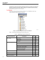
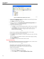
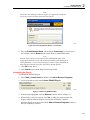
Ansur ESA620
Plug-In
Users Manual
September 2008, 9/09, Rev. 2
© 2008, 2009 Fluke Corporation. All rights reserved. Specifications are subject to change without notice.
All product names are trademarks of their respective companies.
Table of Contents
Chapter
1
Title
Introduction ......................................................................................... 1-1
About This Manual ............................................................................................
Ansur Software ..................................................................................................
Ansur Plug-Ins ...................................................................................................
ESA620 Plug-In.................................................................................................
Test Elements ................................................................................................
Additional References ...................................................................................
Software Updates...........................................................................................
Terms and Abbreviations ..............................................................................
2
1-3
1-3
1-3
1-3
1-4
1-6
1-6
1-7
Getting Started .................................................................................... 2-1
Introduction........................................................................................................
System Requirements ........................................................................................
Installing the ESA620 Plug-In ...........................................................................
Entering License Key ....................................................................................
UnInstalling the Plug-In ................................................................................
Configuring the Plug-In for AAMI Safety Tests ...............................................
Selecting AAMI Nomenclature .....................................................................
Selecting AAMI Terms .................................................................................
3
Page
2-3
2-3
2-3
2-4
2-5
2-6
2-6
2-7
ESA620 Tests....................................................................................... 3-1
Introduction........................................................................................................
Performing a Safety Test ...................................................................................
Load a Test Template ....................................................................................
Start the Template..........................................................................................
Define Patient Modules .................................................................................
Connect the ESA620 .....................................................................................
Perform the Electrical Safety Tests ...............................................................
Storing a Test Record or Template ....................................................................
Printing a Test Report ........................................................................................
Creating an ESA620 Safety Test Template .......................................................
Adding Limits to a Safety Test ..........................................................................
i
3-3
3-3
3-3
3-4
3-6
3-7
3-8
3-10
3-11
3-12
3-14
Ansur ESA620
Users Manual
4
Advanced Features ............................................................................. 4-1
Introduction........................................................................................................
Power Change Delay .........................................................................................
Power Change Pause..........................................................................................
Multiple Earth Resistance Tests.........................................................................
Testing Ultrasound Probes Example..................................................................
Create a Test Template ..................................................................................
Testing the Ultrasound Probes.......................................................................
Basic Test Reports .............................................................................................
5
4-3
4-3
4-4
4-5
4-6
4-6
4-7
4-8
Reference ............................................................................................. 5-1
Introduction........................................................................................................
Electrical Safety Test Elements .........................................................................
Custom Setup.................................................................................................
Expected Results ...........................................................................................
Test Groups........................................................................................................
Custom Setup.................................................................................................
Test Options ..............................................................................................
Test Each Module Separately....................................................................
Test Guide Settings ...................................................................................
Patient Lead Tests .....................................................................................
MAP Settings ............................................................................................
Patient Lead Configuration – Module Setup.............................................
Value Filter ...............................................................................................
Module Filter.............................................................................................
Expected Results ...........................................................................................
Auto Sequence ...................................................................................................
Custom Setup.................................................................................................
Test Options ..............................................................................................
Delay Times ..............................................................................................
Test Each Module Separately....................................................................
Test Guide Settings ...................................................................................
Value Filter ...............................................................................................
Module Filter.............................................................................................
Expected Results ...........................................................................................
Test Guide..........................................................................................................
Module Setup.................................................................................................
Module Groups..........................................................................................
Module Nomenclature...............................................................................
Lead Calibration ............................................................................................
Halt on Test Failure .......................................................................................
Plug-In Preferences............................................................................................
ii
5-3
5-3
5-3
5-3
5-3
5-4
5-4
5-4
5-4
5-5
5-5
5-5
5-5
5-5
5-6
5-6
5-6
5-6
5-7
5-7
5-7
5-7
5-7
5-7
5-7
5-8
5-9
5-10
5-10
5-10
5-11
List of Tables
Table
1-1.
1-2.
3-1.
5-1.
Title
ESA620 Plug-In Electrical Safety Tests ................................................................
Terms and Abbreviations .......................................................................................
ESA620 International Standards ............................................................................
Toolbar Buttons......................................................................................................
iii
Page
1-4
1-7
3-15
5-8
Ansur ESA620
Users Manual
iv
List of Figures
Figure
1-1.
2-1.
2-2.
2-3.
2-4.
2-5.
3-1.
3-2.
3-3.
3-4.
3-5.
3-6.
3-7.
3-8.
3-9.
3-10.
3-11.
3-12.
3-13.
3-14.
3-15.
3-16.
3-17.
3-18.
3-19.
3-20.
3-21.
4-1.
4-2.
4-3.
4-4.
4-5.
4-6.
4-7.
4-8.
Title
Electrical Safety Tests in Ansur's Test Explorer ....................................................
ESA620 Plug-In Installation File Location ............................................................
Ansur Registration Screen - License Key ..............................................................
Removing ESA620 Plug-In....................................................................................
Selecting AAMI Nomenclature..............................................................................
Selecting AAMI Terms ..........................................................................................
Open Dialog Box....................................................................................................
Browsing the Ansur Test Library...........................................................................
Selecting a Ready-Made Test Template.................................................................
Starting a Test Template ........................................................................................
Test Initialization Window.....................................................................................
IEC 60601-1 Test Guide ........................................................................................
Module Setup Window ..........................................................................................
Sample Module Setup Screen ................................................................................
Connecting Instructions for Applied Parts .............................................................
DUT Connected to the Analyzer............................................................................
Completed Safety Test Window ............................................................................
Test Summary Window..........................................................................................
ESA620 Test Record..............................................................................................
Save As Dialog Box ...............................................................................................
Print Report Window .............................................................................................
Print Preview of Test Report..................................................................................
Auto Sequence added to Template.........................................................................
Adding Electrical Safety Tests to the Auto Sequence............................................
Complete IEC 60601-1 Safety Test .......................................................................
Apply When Tab ....................................................................................................
Selecting Standards ................................................................................................
Custom Setup Tab ..................................................................................................
Editing Power On/Off Delay Times.......................................................................
Power On Delay Message ......................................................................................
Safety Test Performing a Power Off Delay (After Power Off)..............................
Stop for Power Configuration Change Message ....................................................
Multiple Protective Earth Resistance Message ......................................................
Configuring Module Testing..................................................................................
Creating Module Groups........................................................................................
v
Page
1-4
2-4
2-5
2-5
2-6
2-7
3-3
3-4
3-4
3-5
3-5
3-6
3-6
3-7
3-7
3-8
3-9
3-9
3-10
3-10
3-11
3-12
3-13
3-13
3-13
3-14
3-15
4-3
4-3
4-4
4-4
4-5
4-5
4-6
4-7
Ansur ESA620
Users Manual
4-9.
4-10.
4-11.
4-12.
4-13.
4-14.
4-15.
5-1.
5-2.
5-3.
5-4.
5-5.
5-6.
5-7.
5-8.
5-9.
5-10.
5-11.
5-12.
5-13.
5-14.
Module Group with Three Ultrasound Probes .......................................................
Connect Applied Parts Window.............................................................................
Add an Earth Leakage Current Test .......................................................................
Assign Maximum Value to a Test Group...............................................................
Remove Test from a Report ...................................................................................
Maximum Value Assigned to the Test Group........................................................
Test Record Showing Value Filtered Report .........................................................
Expected Results with No Applied Parts ...............................................................
Expected Results with Applied Parts .....................................................................
Test Group Custom Setup Window .......................................................................
Module Information ...............................................................................................
Auto Sequence Custom Setup Page .......................................................................
ESA620 Test Guide Window.................................................................................
Module Setup Window ..........................................................................................
Modules in a Module Setup Window.....................................................................
Applied Parts Connection Diagram........................................................................
Module Groups Window........................................................................................
Selecting Module Nomenclature............................................................................
Test Lead Calibration Window ..............................................................................
Halt on Test Failure Window .................................................................................
ESA620 Plug-In Preferences: Module Nomenclature............................................
vi
4-7
4-8
4-9
4-9
4-9
4-10
4-10
5-3
5-3
5-4
5-5
5-6
5-7
5-8
5-9
5-9
5-9
5-10
5-10
5-11
5-12
Chapter 1
Introduction
Title
About This Manual ..............................................................................................
Ansur Software ....................................................................................................
Ansur Plug-Ins .....................................................................................................
ESA620 Plug-In...................................................................................................
Test Elements ..................................................................................................
Additional References .....................................................................................
Software Updates.............................................................................................
Terms and Abbreviations ................................................................................
Page
1-3
1-3
1-3
1-3
1-4
1-6
1-6
1-7
1-1
Ansur ESA620
Users Manual
1-2
Introduction
About This Manual
1
About This Manual
This Users Manual is designed to assist the reader in using the Ansur ESA620 Plug-In
with Ansur software. The manual covers all features specific to the Plug-In. Familiarity
with both Ansur software and Microsoft Windows and their features will help in the
design and use of tests for the Ansur ESA620 Analyzer. The manual is divided into the
following chapters:
Chapter 1 “Introduction” provides information on Ansur software and the ESA620
Plug-In.
Chapter 2 “Getting Started” provides information on how to install and configure the
ESA620 Plug-In.
Chapter 3 “ESA620 Tests” provides step-by-step descriptions on how to perform the
basic tasks of the ESA620 Plug-In.
Chapter 4 “Advanced Features” contains information on creating highly efficient
safety test procedures using the ESA620 Plug-In features.
Chapter 5 “Reference” contains details about every ESA620 Plug-In feature.
Ansur Software
Ansur Test Automation software is the foundation for all Fluke Biomedical test systems.
Ansur manages test procedures by allowing both manual and visual automated test
sequences.
The software works hand-in-hand with Fluke Biomedical analyzers and simulators,
creating a seamless integration for:
•
Visual inspections
•
Preventive maintenance
•
Work procedures
•
Performance tests
•
Electrical safety tests
Ansur Plug-Ins
Ansur Test Executive software utilizes Plug-In modules that work with a wide array of
Fluke Biomedical instruments. The Plug-In module is a software interface that provides
test elements to the Ansur Test Executive program. This scheme allows the use of a
similar user interface for all analyzers and simulators supported by Ansur.
With the purchase of a new Fluke Biomedical analyzer or simulator, it is possible to
update existing Ansur software by installing a new Plug-In. Each Plug-In module allows
users to work with only the options and capabilities needed for the instrument under test.
ESA620 Plug-In
The Ansur ESA620 Plug-In provides remote access to the ESA620 Electrical Safety
Analyzer, referred to throughout this document as the “Analyzer.” In addition to the
general test plug-ins, specialized plug-ins address all test requirements for specific
instruments.
Note
The ESA620 Electrical Safety Analyzer Users Manual explains the
Analyzer’s capabilities and use.
1-3
Ansur ESA620
Users Manual
Create and use Ansur test procedures with Ansur ESA620 test elements to incorporate the
capabilities of an Analyzer into automated testing. Users can customize tests to analyze
specific performance requirements. There are unique test elements for each of the tests,
and simulations typically run on the Analyzer.
Test Elements
The ESA620 electrical safety tests shown in Figure 1-1 are installed to Ansur’s test
explorer during the ESA620 Plug-In installation.
gex01.bmp
Figure 1-1. Electrical Safety Tests in Ansur's Test Explorer
Table 1-1 lists all the ESA620 Plug-In electrical safety tests.
Table 1-1. ESA620 Plug-In Electrical Safety Tests
Unit
Applied
Parts
Live to Neutral
V
No
Neutral to Earth
V
No
Live to Earth
V
No
Normal Condition
V
No
Open Neutral
V
No
Open Earth
V
No
Normal Condition, Reversed Mains
V
No
Open Neutral, Reversed Mains
V
No
Open Earth, Reversed Mains
V
No
MΩ
No
Equipment Current
A
No
Point to Point Voltage
V
No
Point to Point Resistance
Ω
No
Electrical Safety Test
Mains Voltage
Accessible Voltage
Protective Earth Resistance
1-4
Configuration
Introduction
ESA620 Plug-In
1
Table 1-1. ESA620 Plug-In Electrical Safety Tests (cont.)
Unit
Applied
Parts
μA
No
Mains to Protective Earth
MΩ
No
Applied Parts to Protective Earth
MΩ
All
Mains to Applied Parts
MΩ
All
Mains to Non-Earth Accessible Conductive Part
MΩ
No
Applied Parts to Non-Earth Accessible Conductive
Part
MΩ
All
Normal Condition
μA
No
Open Neutral
μA
No
Normal Condition, Reversed Mains
μA
No
Open Neutral, Reversed Mains
μA
No
Normal Condition
μA
No
Open Neutral
μA
No
Open Earth
μA
No
Normal Condition, Reversed Mains
μA
No
Open Neutral, Reversed Mains
μA
No
Open Earth, Reversed Mains
μA
No
Normal Condition
μA
Yes
Open Neutral
μA
Yes
Open Earth
μA
Yes
Normal Condition, Reversed Mains
μA
Yes
Open Neutral, Reversed Mains
μA
Yes
Open Earth, Reversed Mains
μA
Yes
Single Fault Condition
μA
Yes
Single Fault Condition, Reversed Mains
μA
Yes
Normal Condition
μA
Yes
Open Neutral
μA
Yes
Open Earth
μA
Yes
Normal Condition, Reversed Mains
μA
Yes
Open Neutral, Reversed Mains
μA
Yes
Open Earth, Reversed Mains
μA
Yes
μA
No
μA
No
Electrical Safety Test
Configuration
Point to Point Leakage
Insulation Resistance
Earth Leakage Current
Enclosure Leakage Current
Patient Leakage Current
Mains on Applied Parts
Patient Auxiliary Current
Alternative Equipment Leakage Closed Earth
Open Earth
1-5
Ansur ESA620
Users Manual
Table 1-1. ESA620 Plug-In Electrical Safety Tests (cont.)
Unit
Applied
Parts
Normal Condition
μA
No
Open Earth
μA
No
Normal Condition, Reversed Mains
μA
No
Open Earth, Reversed Mains
μA
No
Normal Condition
μA
No
Open Earth
μA
No
Normal Condition, Reversed Mains
μA
No
Open Earth, Reversed Mains
μA
Yes
Normal Condition
μA
Yes
Normal Condition, Reversed Mains
μA
No
Normal Condition
μA
Yes
Open Neutral
μA
Yes
Open Earth
μA
Yes
Normal Condition, Reversed Mains
μA
Yes
Open Neutral, Reversed Mains
μA
Yes
Open Earth, Reversed Mains
μA
Yes
Normal Condition
μA
Yes
Electrical Safety Test
Differential Leakage
Direct Equipment Leakage
Direct Applied Part Leakage
Accessible Leakage
Alternative Applied Part
Leakage
Configuration
The ESA620 Plug-In provides three types of test elements: Auto Sequence, Test Groups,
and Electrical Safety Tests.
Auto Sequence is a test container containing any of the ESA620 test elements. An Auto
Sequence will execute all tests contained within it. An Auto Sequence also provides
additional test setup such as power on/off delay time and test optimization.
Test Groups are specialized Auto Sequences, one for each group of safety test (e.g. Earth
Leakage Current).
Electrical safety tests are indicated in the Test Explorer window with a light-blue icon.
Each safety test element corresponds to a measurement available in the ESA620 Safety
Analyzer.
Additional References
In addition to this manual, answers to questions using the Analyzer or PC may be found
in the following sources:
•
Fluke Biomedical ESA620 Users Manual
•
Fluke Biomedical Ansur Test Executive Users Manual
•
Microsoft Windows Help and Support Center
Software Updates
Updates for Ansur are published on the Fluke Biomedical website,
http://www.flukebiomedical.com.
1-6
Introduction
ESA620 Plug-In
1
Terms and Abbreviations
Table 1-2 lists terms and abbreviations used in this manual.
Table 1-2. Terms and Abbreviations
Term
Description
Ansur
Ansur is a software suite using plug-ins to perform test and inspection procedures in
conjunction with several Fluke Biomedical test instruments.
DUT
Device Under Test—the equipment subjected to a test using the Analyzer
DUT Info
Information used to identify one particular DUT. DUT info usually consists of a serial
number, manufacturer, device type and model. Ansur also adds a few extra data
fields such as location and status.
ESA620
Electrical Safety Analyzer from Fluke Biomedical
Field User
The person using Ansur to perform a test template on a DUT.
Module Setup
Module setup contains information about all patient leads that are to be connected
to the ESA620 when testing one specific DUT.
Plug-In
Add-on software program that extends Ansur so that it can interface with a specific
Fluke Biomedical test instrument to configure it for a specific test and to
automatically collect the measured data (if applicable)
Test Container
A test container is a test element that can contain other test elements. The ESA620
Auto Sequence is a test container
Test Element
An Ansur construct that encapsulates test configuration and results
A test template is built of several test elements.
Test Guide
A window displayed by Ansur or any of its plug-ins when a test element is being
performed
Test Record
An Ansur file containing the results of a performed test template
The test record can be printed as a test report.
Test Template
An Ansur file containing a set of test elements that define how a particular DUT is to
be tested
A test template can also contain instructions on how to perform service, preventive
maintenance, repair, and other tasks on a DUT.
1-7
Ansur ESA620
Users Manual
1-8
Chapter 2
Getting Started
Title
Introduction..........................................................................................................
System Requirements ..........................................................................................
Installing the ESA620 Plug-In .............................................................................
Entering License Key ......................................................................................
UnInstalling the Plug-In ..................................................................................
Configuring the Plug-In for AAMI Safety Tests .................................................
Selecting AAMI Nomenclature .......................................................................
Selecting AAMI Terms ...................................................................................
Page
2-3
2-3
2-3
2-4
2-5
2-6
2-6
2-7
2-1
Ansur ESA620
Users Manual
2-2
Getting Started
Introduction
2
Introduction
This chapter describes installation of the ESA620 Plug-In and its use together with the
Ansur Test Automation software and the Analyzer.
Note
An Analyzer is not necessary to create test templates and experiment with
the functionality available in Ansur and the ESA620 Plug-In. However,
actual tests cannot be performed unless the Analyzer is connected to the
computer.
System Requirements
The following are recommended minimum requirements for installation:
•
IBM PC/XT-compatible Pentium II 350 MHz or faster processor
•
128 MB of ram
•
Microsoft Windows 2000 or Windows XP or Vista operating system
•
Fluke Biomedical Ansur V2.8.2 or newer
•
50 MB of available hard drive for software
•
Hard drive space (from 100 k to several megabytes) for result and template files
Installing the ESA620 Plug-In
The ESA620 Plug-In must be installed on the computer before the features described in
this user manual can be implemented. For information on obtaining the Ansur software
and the ESA620 Plug-In, contact the local Fluke Biomedical representative or visit the
Fluke Biomedical website (http://www.flukebiomedical.com).
Note
Ansur version 2.8.2 or newer must be installed before the ESA620 Plug-In
can be installed and used.
Download the ESA620 Plug-In from the Fluke Biomedical website and follow the steps
below:
Note
When downloading the ESA620 Plug-In from the Fluke Biomedical
web site, it is possible to run the installation without first downloading.
Note
When installing Ansur or any of its components/plug-ins on computers
running Microsoft Vista, it is important to perform the installation as the
Administrator for that computer. Otherwise the registry will not be properly
updated and Ansur will not work properly. For installing on Windows
Vista, you must first download the file to your local computer, then locate
the installation file, right click and select “Run as Administrator.”
1. Open Windows Explorer and browse to the saved ESA620 Plug-In installation
program file, usually named Ansur ESA620 Plug-In Vn.n.n.exe, where n.n.n is
the Plug-In version number. See Figure 2-1.
2-3
Ansur ESA620
Users Manual
Figure 2-1. ESA620 Plug-In Installation File Location
gex02.bmp
2. Double-click the installation program. The installation extracts the Plug-In elements
and displays the Welcome dialog box.
3. Click Next to display the license agreement.
4. Select the checkbox for “I accept the terms in the license agreement,” and
click Next to display the default destination folder.
5. Choose one of the following options:
•
Click Next to accept the default destination folder in which Ansur was installed.
•
Click Change if Ansur has been installed in a different folder. In this case, the
destination folder for the Plug-In is changed so that it resides in the same
directory as the Ansur program.
Note
If Ansur has been installed in a different destination folder from the default,
be sure to use the same folder for the ESA620 Plug-In.
6. Click Install to begin the installation. A progress bar indicates the status of the PlugIn installation.
After a few minutes, the installation concludes, and the window displays the dialog
box and the Finish button.
7. Click Finish. The Plug-In will load when Ansur is started.
Entering License Key
When using the Plug-In for the first time, the user is prompted to enter a software license
key provided by Fluke Biomedical at the time of purchase.
Note
Test templates can be created without a license key by using the
demonstration mode. Demonstration mode allows many of the tasks
described in this user manual. However, a user may not save or print
without licensing the Plug-In.
1. Start Ansur by doing one of the following:
2-4
•
Double-click the Ansur icon on the desktop.
•
From the Start menu, select Start | Programs | Fluke | Ansur.
Getting Started
Installing the ESA620 Plug-In
2
Note
The license key dialog box shown in Figure 2-2 appears at startup if a
license key has not yet been entered for the Plug-In.
Figure 2-2. Ansur Registration Screen - License Key
gex03.bmp
2. Enter the Establishment Name and the Plug-In license key. If a license key is
not available, click the Demo button to start Ansur in demonstration mode.
Note
Because the license key is derived from the establishment name, both
strings must match the license information provided by Fluke Biomedical.
This information is case sensitive and space sensitive. If the establishment
name has been entered in the past, this field is already filled in
3. Click OK to start Ansur.
4. Click Cancel to prevent the Plug-In from being loaded.
UnInstalling the Plug-In
To uninstall the ESA620 Plug-In:
1. Select Start | Control Panel and double-click Add or Remove Programs.
2. Locate and select the entry named Ansur ESA620 Plug-in.
Figure 2-3. Removing ESA620 Plug-In
gex04.bmp
3. With the entry highlighted, click the Remove button as shown in Figure 2-3.
4. When asked to verify the removal, click Yes. A dialog box with a progress bar
displays while the ESA620 Plug-In is being removed from the computer.
When the Plug-In is no longer listed in the Add or Remove Programs window, it
has been completely removed.
2-5
Ansur ESA620
Users Manual
Configuring the Plug-In for AAMI Safety Tests
At installation, the ESA620 Plug-In is configured for IEC nomenclature patient lead
classification names. Configuring the Plug-In for AAMI testing requires changing two
settings: Module Nomenclature and User Interface Language.
Module nomenclature determines patient lead classification and how they are tested. IEC
uses protection classes Body, Body Float, and Cardiac Float for patient lead while AAMI
uses protection classes Non-Isolated and Isolated.
IEC terms are used for the English (default) user interface language. AAMI terms are
used for the English US language.
Note
This manual uses the IEC graphics and terms. Changing the configuration
to AAMI will cause some displays to appear on your PC that are different
than those in this manual.
Selecting AAMI Nomenclature
To change the Plug-In configuration to AAMI:
1. Start Ansur and click Tools | Options to display the preferences window.
2. Click ESA620 Safety Analyzer to display the ESA620 preferences.
3. Click on the Nomenclature tab to display the Module Nomenclature page.
Click AAMI Terms to highlight AMMI terms and the description. See Figure 2-4.
Figure 2-4. Selecting AAMI Nomenclature
4. Click on OK to close the preference window.
Now AAMI is the default nomenclature when defining patient leads.
Note
Changing module nomenclature will not be affect the limits applied to the
electrical safety tests.
2-6
gex05.bmp
Getting Started
Configuring the Plug-In for AAMI Safety Tests
2
Selecting AAMI Terms
To select AAMI terms for tests:
1. Start Ansur and click Tools | Options to display the preferences window.
2. Click Ansur Preferences and then click on the Language tab to display the User
Interface Language page.
3. Select English US from the list. See Figure 2-5.
Figure 2-5. Selecting AAMI Terms
gex06.bmp
4. Click on OK to close the preferences window.
Note
Ansur must be restarted for the language changes to take effect.
After restarting Ansur, the ESA620 Plug-In will be using AAMI terms for electrical
safety tests and all test related windows.
2-7
Ansur ESA620
Users Manual
2-8
Chapter 3
ESA620 Tests
Title
Introduction..........................................................................................................
Performing a Safety Test .....................................................................................
Load a Test Template ......................................................................................
Start the Template............................................................................................
Define Patient Modules ...................................................................................
Connect the ESA620 .......................................................................................
Perform the Electrical Safety Tests .................................................................
Storing a Test Record or Template ......................................................................
Printing a Test Report ..........................................................................................
Creating an ESA620 Safety Test Template .........................................................
Adding Limits to a Safety Test ............................................................................
Page
3-3
3-3
3-3
3-4
3-6
3-7
3-8
3-10
3-11
3-12
3-14
3-1
Ansur ESA620
Users Manual
3-2
ESA620 Tests
Introduction
3
Introduction
This chapter describes the operation of the Ansur ESA620 Plug-In program.
Performing a Safety Test
Several ready-to-use test templates are copied to the Ansur Test Library folder when the
Plug-In was installed. These templates contain complete electrical safety tests for the
most common ESA620 supported standards.
Note
The supplied test templates can be used as a starting point when creating
new customized test templates. Load a template, alter it by adding visual
inspections and editing the safety test for the specific need and then use
Save As to give it another name.
Load a Test Template
To load a test template:
1. Click File → Open on the menu bar or click on the Open Template toolbar button
( ) to open the dialog box shown in Figure 3-1.
Figure 3-1. Open Dialog Box
gbv09.bmp
2. Browse to the folder where Ansur was installed and double-click the Ansur Test
Library folder. See Figure 3-2. The normal location is C:\Program Files\Fluke but
may have a different name depending on the operating system language.
3-3
Ansur ESA620
Users Manual
Figure 3-2. Browsing the Ansur Test Library
gex10.jpg
3. Double-click the ESA620 folder to open a dialog box that lists the folder names of
the most common medical standards and regulator boards as shown in Figure 3-3.
Figure 3-3. Selecting a Ready-Made Test Template
gbv11.bmp
4. Double-click the folder containing the desired standard and safety test.
5. Click a file name and then click the Open button, or double-click the file name to
load the selected template and display its contents.
Start the Template
After loading the template, start a test by doing the following:
1. Click Test → Start Test or click the Start Test toolbar button (
test initialization window as shown in Figure 3-4.
3-4
) to display
ESA620 Tests
Performing a Safety Test
3
gbv13.bmp
Figure 3-4. Starting a Test Template
Note
When using Ansur version 2.3.2 or newer, the test initialization window will
not be displayed. Instead Ansur will automatically select the standards used
in the template and go directly to the first test guide window. Continue to
the Define Patient Modules section.
2. Select the standard from the list in the Test Initialization window shown in Figure 3-5
that corresponds with the selected test template. For example, if IEC 60601 test
template is opened, then select 60601 standard and deselect the Ansur User Defined
standard that is selected by default.
Figure 3-5. Test Initialization Window
gbv14.bmp
3. Click the Next toolbar button to go to the first Test Guide window shown in Figure 36.
3-5
Ansur ESA620
Users Manual
Figure 3-6. IEC 60601-1 Test Guide
gex37.bmp
Define Patient Modules
The ESA620 Safety Analyzer can test applied parts from different modules in the same
test run. A patient module can be ECG electrodes, SpO2 sensors, temperature sensors,
and others. To define a patient module:
1. Click the Module Setup tab on the left-hand side of the Test Guide to open the
Module Setup page as shown in Figure 3-7.
Figure 3-7. Module Setup Window
gex07.bmp
Note
If AAMI module nomenclature is selected, the module class options will be
different than those shown in Figure 3-7.
2. To define a new module, click the plus button ( ) next to the page title. A module
labeled New is added to the list of modules and a table with module information
fields is displayed in the right-hand frame.
3. Select the appropriate module class, the number of patient leads, and enter a module
code for each module tested. Figure 3-8 shows a sample module for a patient
3-6
ESA620 Tests
Performing a Safety Test
3
monitor.
Figure 3-8. Sample Module Setup Screen
gex08.bmp
Connect the ESA620
The ESA620 Plug-In gives instructions on how to connect the ESA620 to the DUT’s
applied parts. To see the connection instructions:
1. Click the Procedure tab on the left-hand side of the test guide to display the
connection procedure. An applied parts connection guide is shown in Figure 3-9.
Figure 3-9. Connecting Instructions for Applied Parts
gex09.bmp
2. Connect the DUT to the safety analyzer as shown in Figure 3-10. Ensure the
connections are made per the connection instructions.
3. Connect a USB printer cable between a USB port on your computer and the
computer port on the ESA620.
4. Power on the ESA620 Safety Analyzer and the DUT.
3-7
Ansur ESA620
Users Manual
To protective earth or enclosure
Figure 3-10. DUT Connected to the Analyzer
faw03.eps
Perform the Electrical Safety Tests
To run the safety test:
1. Click the Start Test button (
) on the toolbar of the Test Guide.
A progress bar will display in the lower-right corner of the Test Guide window while
the ESA620 Plug-In searches for the ESA620 Safety Analyzer. The safety test will
start when a connection is established. As each test is performed, it is highlighted in
the results frame. When the safety analyzer determines the test result, the results are
displayed next to the test.
Note
If the ESA620 is not connected to COM1 on the PC, Ansur displays an
Instrument Not Found window where the port the ESA620 is
connected to can be entered. The correct port number is displayed in
the Windows Device Manager. Look for the USB Serial Port entry
under “Ports.”
Once the PC locates which port the ESA620 is connected to, Ansur
remembers the port number and uses it as the default port for
electrical safety tests.
Depending on how the loaded template is configured, different instructions may be
displayed while the safety test is running. During a normal test run, instructions to
calibrate the test leads or change the applied part connections may appear. If a safety
test fails, a message appears asking how the failure is to be handled. See “Halt on
Test Failure” in Chapter 5 (Reference).
When the test is completed, the status bar in the lower-right corner of the Test Guide
is updated, the progress bar disappears, and the Start Test button is no longer
highlighted. Figure 3-11 is a sample of a completed safety test window.
3-8
ESA620 Tests
Performing a Safety Test
Figure 3-11. Completed Safety Test Window
2. Click the Next button (
12.
gex10.bmp
) to open the Test Summary window as shown in Figure 3-
Figure 3-12. Test Summary Window
3. Click the Next button (
ESA620 Test Record.
3
gex11.bmp
) to create a Test Record. Figure 3-13 is a sample of an
3-9
Ansur ESA620
Users Manual
gex12.bmp
Figure 3-13. ESA620 Test Record
Each Automatic Sequence may have its own Patient Lead configuration. The
configuration for the selected test element is displayed in the Plug-In Test Setup.
Storing a Test Record or Template
Each test record and test template created with the Plug-In can be saved to a file on the
PC. To save a test record or template:
1. Click File Save on the main menu or click the save toolbar button (
dialog box opens as shown in Figure 3-14.
Figure 3-14. Save As Dialog Box
). The Save As
gbv24.bmp
2. Browse to the correct location and enter a filename in the file name field and click
3-10
ESA620 Tests
Printing a Test Report
3
the Save button or press the Enter key. The file is saved and the Ansur title bar is
updated with the new name.
Printing a Test Report
Test reports can be printed in three different formats from the test record:
•
Summary – A report containing DUT information, module setup, and the overall
status of the safety test. This one-page report is good for a simple Pass or Fail
report.
•
Condensed – A report containing the summary report information as well as
each test element on a single line showing whether the test passed or failed.
•
Detailed – A report containing the summary and condensed information along
with all configuration data and test result data.
1. With the Test Report open, click File Print or click the toolbar Print button to open
the Print Report window shown in Figure 3-15.
Figure 3-15. Print Report Window
gbv26.bmp
2. Select the desired print type and click the Print button to display the report in the
preview window as shown in Figure 3-16.
3-11
Ansur ESA620
Users Manual
Figure 3-16. Print Preview of Test Report
3. Print the report by clicking on the Print button (
gex38.bmp
) in the left-hand window border.
Note
To skip the preview before printing, uncheck the Show Preview checkbox in
the print report window shown in Figure 3-15.
Creating an ESA620 Safety Test Template
A test template is an Ansur file containing a set of test elements that define how a
particular DUT is to be tested. Once created, the test template can be used to test other
DUTs of the same type. A test template can also contain instructions on how to perform
service, preventive maintenance, repair, and other tasks on a DUT.
To create a new test template:
1. Open a blank test template by clicking on File → New → Template or click the
New Template button ( ) on the main toolbar.
2. In the test explorer window, click on the plus button next to the ESA620 Safety
Analyzer entry to expand the electrical safety test entries for this analyzer.
To create a safety test made up of several measurements that are executed sequentially,
an auto sequence test element must be created to hold the tests.
3. Click and hold on the Auto Sequence entry in the test explorer window and drag and
3-12
ESA620 Tests
Creating an ESA620 Safety Test Template
3
release it in the template window. A copy of the Auto Sequence should appear in the
template window as shown in Figure 3-17. The Auto Sequence entry is a holder of
tests that are executed when called.
Figure 3-17. Auto Sequence added to Template
gex13.eps
4. To add tests to the Auto Sequence, click and hold on the desired test in the Test
Explorer window and drag it to directly over the Auto Sequence entry in the
Template Window and release it. The Mains Voltage test is added to the Auto
Sequence shown in Figure 3-18.
Figure 3-18. Adding Electrical Safety Tests to the Auto Sequence
gex14.bmp
Note
If a test is dragged and released UNDER the Auto Sequence entry and not
on it, the test will not be performed as a part of the Auto Sequence. It will
be performed when the Auto Sequence is completed displaying its own Test
Guide where the operator will have to click the Play button in order to
perform the test.
Repeat step 4 for each test that should be included in the Auto Sequence. A complete IEC
60601-1 safety test will look similar to the test template shown in Figure 3-19.
Figure 3-19. Complete IEC 60601-1 Safety Test
gex15.bmp
3-13
Ansur ESA620
Users Manual
Adding Limits to a Safety Test
The ESA620 Safety Analyzer performs electrical safety tests in accordance with several
major medical standards. A Test Template allows the selection of limits for the different
electrical safety tests. It is also possible to define your own test limits. For example,
check that a specific DUT maintains its factory specifications.
To select an appropriate standard for a test:
1. Select a safety test in the template window.
2. Click the Apply When tab below the list of test elements as shown in Figure 3-20.
Figure 3-20. Apply When Tab
gex16.bmp
3. Click on the standard(s) to which you want to add a limit value. The list of standards
shown in Figure 3-21 may be different depending on the currently installed Plug-In.
The International Standards that are used by the ESA620 Plug-In are listed in
Table 3-1.
Figure 3-21. Selecting Standards
Note
When a safety test is a part of a test container, for instance an Auto
Sequence, the standards listed on the safety test will include only
those selected on the parent test container.
3-14
gbv33.bmp
ESA620 Tests
Adding Limits to a Safety Test
3
Table 3-1. ESA620 International Standards
Standard
Use
AAMI/NFPA-99 (H)
Hospital
AAMI/NFPA-99 (M)
Manufacturer
AAMI ES60601-1
AS/NZS 3551
IEC 60601
IEC 62353 (CL1)
Class 1 equipment
IEC 62353 (CL2)
Class 2 equipment
MDA DB9801S1A
MDB DB9801S1B
VDE 751.1 (CL1)
Class 1 equipment
VDE 751.1 (CL2)
Class 2 equipment
When adding a test element to a test template, Ansur selects the Ansur User Defined
standard by default. If a test requires a particular resistance load, then only one
standard should be selected. The ESA620 will be configured to use the test load of
the first standard that was selected when creating the test template. Ansur filters the
tests on the standards. Therefore a test marked for IEC601.1 only, will not be
performed if you perform the test selecting AAMI/NFPA-99 as the only standard.
To select one standard for all tests within a test container, select the test container
entry and then select the standard in the apply when performing list. For example,
select the Auto Sequence entry in the template window and then select a standard.
All tests in the Auto Sequence will now have the same standard applied to each test.
4. Enter a limit value by clicking on the Expected Results tab.
5. Click the High or Low cell under the desired standard. The selected row is
highlighted and a cursor is displayed in the cell that was checked.
6. Enter the limit value for the selected safety test.
Note
If an international standard has statutory limits, then these limits are
always enforced. Statutory limits cannot be altered by the user and are
indicated with a padlock ( ).
3-15
Ansur ESA620
Users Manual
3-16
Chapter 4
Advanced Features
Title
Introduction..........................................................................................................
Power Change Delay ...........................................................................................
Power Change Pause............................................................................................
Multiple Earth Resistance Tests...........................................................................
Testing Ultrasound Probes Example....................................................................
Create a Test Template ....................................................................................
Testing the Ultrasound Probes.........................................................................
Basic Test Reports ...............................................................................................
Page
4-3
4-3
4-4
4-5
4-6
4-6
4-7
4-8
4-1
Ansur ESA620
Users Manual
4-2
Advanced Features
Introduction
4
Introduction
This chapter describes the advanced features of the ESA620 Plug-In. This chapter
assumes the reader is already familiar with the basic tasks described in chapter 3.
Power Change Delay
Some devices require time to stabilize after cycling power on or off. It is important to
delay running electrical safety tests until the device stabilizes. The Auto Sequence can be
delayed for a specified time to allow a device to stabilize after its power has been turned
off or on. To enter a time delay:
1. Select Auto Sequence in the template window and click the Custom setup tab
to open the custom setup window.
As shown in Figure 4-1, there are two delay settings under Delay Times in the
General Test Group Settings section of the custom setup window: Power Up and
Power Off delay times.
Figure 4-1. Custom Setup Tab
gex17.bmp
2. To set a delay in seconds after the DUT is turned on, click on Power on delay
time and enter a number between 0 and 9,999.
3. To set a delay in seconds after the DUT is turned off, click on Power off delay
time and enter a number between 0 and 9,999. Once a number is entered in this field,
you can select whether the delay is applied before or after power is turned off. After
power off is the default setting.
Using the example in Figure 4-2, a 20 second delay is inserted each time the outlet on the
ESA620 is powered on. A delay of 7 seconds is inserted each time the outlet is powered
off.
Figure 4-2. Editing Power On/Off Delay Times
gbv36.bmp
The dialog box shown in Figure 4-3 is displayed whenever a delay is executed.
4-3
Ansur ESA620
Users Manual
Figure 4-3. Power On Delay Message
gbv37.bmp
A delay is inserted each time the power is switched off for a period of time set in the
Delay Times dialog box for power off delay time (s) as shown in Figure 4-2. The dialog
box shown in Figure 4-4 is displayed to indicate progress while the Plug-In waits to
continue the safety test (Delay = After Power Off).
Figure 4-4. Safety Test Performing a Power Off Delay (After Power Off)
gex18.bmp
If the delay is set to Before Power Off, the dialog box in Figure 4-4 is displayed.
Power Change Pause
Some devices require more than a delay each time DUT power is turned on or off. One
example is a device that does not turn on after a power failure. In this case, personnel
must turn the device back on. To work with this device, the Auto Sequence can be
programmed to stop or pause whenever the power configuration changes on the ESA620
equipment outlet. There two pause options: Stop before and stop after new power
configuration.
Stop before new power configuration – Causes the Auto Sequence to display a message
before power on the ESA620 equipment outlet is changed.
Stop after new power configuration – Causes the Auto Sequence to display a message
after power on the ESA620 equipment outlet is changed.
1. Select Auto Sequence in the template window and click the Custom setup tab
to open the custom setup window.
As shown in Figure 4-1, there are several settings under Test Options in the General
Test Group Settings section of the custom setup window. Two settings are labeled
Stop before new power configuration and stop after new power configuration.
2. To pause the safety test before a new power configuration is applied to the equipment
outlet, click Stop before new power configuration.
4-4
Advanced Features
Multiple Earth Resistance Tests
4
3. To pause the safety test after a new power configuration is applied to the equipment
outlet, click Stop after new power configuration.
The dialog box shown in Figure 4-5 is displayed whenever a pause is executed.
Continue must be clicked to continue the safety test.
Figure 4-5. Stop for Power Configuration Change Message
gex19.jpg
Note
When a stop before or stop after new power configuration option is
enabled, the power on and power off delay times are ignored.
Multiple Earth Resistance Tests
To allow taking Protective Earth (PE) Resistance measurements at several test points on a
DUT during one safety test, the ESA620 Plug-In can be set to repeat the PE test. To set
up the plug-in for multiple PE tests:
1. Select Auto Sequence in the template window and click the Custom setup tab
to open the custom setup window.
As shown in Figure 4-1, there are several settings under Test Options in the General
Test Group Settings section of the custom setup window.
2. To perform multiple PE tests, click Perform multiple PE tests.
The dialog box shown in Figure 4-6 is displayed whenever multiple protective earth
resistance tests is enabled. Clicking the Repeat button repeats the test while clicking
Continue moves the Auto Sequence on to the next test. Checking the Save multiple
results checkbox will cause each PE test to be saved.
Figure 4-6. Multiple Protective Earth Resistance Message
gex20.bmp
Note
If the Save multiple results checkbox is not checked, only the last Protective
Earth Resistance test will be saved with the test results. Otherwise each
Protective Earth Resistance test result is saved with the test results.
4-5
Ansur ESA620
Users Manual
Testing Ultrasound Probes Example
Ultrasound machines may have more than one probe. Only one probe can be attached to
the ESA620 at any given time while a safety test is performed. However, the ESA620
Plug-In supports such situations by testing each probe separately through module groups.
Module groups allow the testing of several modules connected to the same patient lead
input.
Create a Test Template
To create a test template for ultrasound probes:
1. Create a test template with an Auto Sequence test containing a Patient Leakage
Current and a Patient Auxiliary current test group. See the “Creating an ESA620
Safety Test Template” section in Chapter 3 for more information.
2. Click the Auto Sequence in the template window and click Custom setup.
3. Click the Test Each Module Separately, Expand module groups, and Stop at new
module checkboxes in the General Test Group Settings area as shown in Figure 4-7.
Figure 4-7. Configuring Module Testing
gex21.bmp
4. Define the patient modules with ultrasound probes by starting the template and
proceed to the Test Guide for the Auto Sequence test.
5. Click the Module Setup tab and add a new module of type CF with one lead. There is
no need to enter module information at this point.
6. Click the Group checkbox.
The currently selected module is displayed as Group in the module list as shown in
Figure 4-8. A new module is inserted below the group, slightly indented and the Module
Type and No of Leads fields are disabled.
4-6
Advanced Features
Testing Ultrasound Probes Example
Figure 4-8. Creating Module Groups
4
gex22.bmp
7. Enter Abdominal as the Module code for the new module.
8. Click the plus button ( ) to add a new module within the group. Ensure the module
currently within the group is selected, otherwise the new module will be placed
outside the group.
9. Enter Endovaginal as Module code for the new module, and add another module
named Vascular.
As shown in Figure 4-9, the module setup now contains a group with three modules
inside it.
Figure 4-9. Module Group with Three Ultrasound Probes
gex23.bmp
Testing the Ultrasound Probes
Ultrasound probes normally don’t have an electrical connection. To perform a safety test
on them, fill a container with an electrical conducting liquid (e.g. a salt water solution) in
which the probe and test lead will be placed.
1. Connect one end of a test lead to the ESA620 as shown in the test guide. Put the other
end in the conducting liquid.
4-7
Ansur ESA620
Users Manual
Note
To determine where to connect the test lead, return to the procedure page
by clicking the Procedure tab in the Test Guide. The module group just
created will be displayed as Group in the patient lead setup. To see the
contents of the group, hover the mouse pointer above the group title and a
tool tip will pop up and display the Module code of every module inside the
group.
2. Click the Start Test button (
start the test.
) on the Test Guide’s toolbar. Alternately push F9 to
The safety test starts and a progress bar in the lower-left corner starts moving. If the test
does not start, see the “Connect the ESA620” section in Chapter 3. After a short while,
the Connect Applied Parts window shown in Figure 4-10 appears, instructing you to
connect the first probe to patient lead 1.
Figure 4-10. Connect Applied Parts Window
gex24.bmp
3. When instructed to connect the first probe (Abdominal), connect it to the ultrasound
machine and submerse it in the liquid with the test lead.
4. Click Continue to continue performing the electrical safety tests on the abdominal
probe.
5. When the Connect Applied Parts window reappears instructing you to connect the
next probe, disconnect the first probe and connect the second probe to the ESA620.
Submerse the probe in the liquid with the test lead.
6. Repeat steps 4 and 5 for the vascular probe.
Basic Test Reports
The amount of detail contained in a test report is adjustable with the value filter built into
the Auto Sequence and Test Groups. The example below shows the steps to get a report
with only the worst case value from a test.
1. Create a new test template and add an Earth Leakage Current test group as shown in
Figure 4-11.
4-8
Advanced Features
Basic Test Reports
Figure 4-11. Add an Earth Leakage Current Test
4
gex25.bmp
2. Click the test group in the template window and click the Custom setup tab to display
the options shown in Figure 4-12.
Figure 4-12. Assign Maximum Value to a Test Group
gbv49.bmp
3. Under Value Assigned to Test Group click Maximum value option.
4. Expand the test group and click the first safety test (Normal Condition), then click the
Apply When tab.
5. Uncheck Include in report which is found in the Report Level frame shown in
Figure 4-13.
Figure 4-13. Remove Test from a Report
gbv50.bmp
6. Repeat step 4 and 5 for every safety test inside the Earth Leakage Current test group.
7. Perform the safety test.
When the safety test is complete, the Earth Leakage Current test group (the row with
caption written in bold face font) is updated with the maximum value recorded by any of
the Earth Leakage Current tests. See Figure 4-14.
4-9
Ansur ESA620
Users Manual
Figure 4-14. Maximum Value Assigned to the Test Group
gex26.bmp
8. Continue to the test record window.
As shown in Figure 4-15 only the test group appears in the test record. When a test report
is printed it will also show only the test group with the maximum (worst case) value of all
the performed Earth Leakage Current tests.
Figure 4-15. Test Record Showing Value Filtered Report
4-10
gex27.bmp
Chapter 5
Reference
Title
Introduction..........................................................................................................
Electrical Safety Test Elements ...........................................................................
Custom Setup...................................................................................................
Expected Results .............................................................................................
Test Groups..........................................................................................................
Custom Setup...................................................................................................
Test Options ................................................................................................
Test Each Module Separately......................................................................
Test Guide Settings .....................................................................................
Patient Lead Tests .......................................................................................
MAP Settings ..............................................................................................
Patient Lead Configuration – Module Setup...............................................
Value Filter .................................................................................................
Module Filter...............................................................................................
Expected Results .............................................................................................
Auto Sequence .....................................................................................................
Custom Setup...................................................................................................
Test Options ................................................................................................
Delay Times ................................................................................................
Test Each Module Separately......................................................................
Test Guide Settings .....................................................................................
Value Filter .................................................................................................
Module Filter...............................................................................................
Expected Results .............................................................................................
Test Guide............................................................................................................
Module Setup...................................................................................................
Module Groups............................................................................................
Module Nomenclature.................................................................................
Lead Calibration ..............................................................................................
Halt on Test Failure .........................................................................................
Plug-In Preferences..............................................................................................
Page
5-3
5-3
5-3
5-3
5-3
5-4
5-4
5-4
5-4
5-5
5-5
5-5
5-5
5-5
5-6
5-6
5-6
5-6
5-7
5-7
5-7
5-7
5-7
5-7
5-7
5-8
5-9
5-10
5-10
5-10
5-11
5-1
Ansur ESA620
Users Manual
5-2
Reference
Introduction
5
Introduction
This chapter contains additional information on some of the ESA620 Plug-In features.
Electrical Safety Test Elements
Each electrical safety test corresponds to a unique measurement available on the ESA620
Safety Analyzer. When the electrical safety test element is executed within an Ansur test
template, the returned measurement is compared to defined limits. This comparison
determines if the test element passed or failed.
The most noticeable difference is between electrical safety tests measured on applied
parts and those measured on other parts on the DUT (e.g. its enclosure). Before
measurements are taken, the applied parts configuration for the DUT is grouped into a
number of modules. Electrical safety tests measured on applied parts will be run for each
module and so the measurements returned are displayed against the list of modules.
Custom Setup
There is no limitation placed on how the measurement is performed for a electrical safety
test element.
Expected Results
Electrical safety tests that are not performed on applied parts will contain only one limit
entry for each selected standard as shown in Figure 5-1.
Figure 5-1. Expected Results with No Applied Parts
gbv53.bmp
Electrical safety tests performed on applied parts will contain two or three limit entries
for each selected standard. This is because applied parts can be one of three IEC classes
(Body, Body Float, or Cardiac Float) or one of two AAMI classes (Non-Isolated or
Isolated). In Ansur, it is possible to define limits against any of these classes. Figure 5-2
shows the results window on an applied part using the IEC classes.
Figure 5-2. Expected Results with Applied Parts
gbv54.bmp
Test Groups
Test groups come with a number of predetermined child safety test elements. These child
elements are the same measurement but with varying power configurations. It is possible
to drop other tests into this container but it is ill advised.
5-3
Ansur ESA620
Users Manual
The test group is passed only if all of its child elements pass and the test group’s value
satisfy its expected results.
Custom Setup
The Test Group’s custom setup enables the operator to configure how the group will be
performed. Figure 5-3 shows the custom setup window.
Figure 5-3. Test Group Custom Setup Window
gex28.bmp
Test Options
When Halt on test failure is selected, the test will stop each time a safety test violates
its limits. The Plug-In will display the window described in the “Halt of Test Failure”
section later in this chapter.
Test Each Module Separately
Usually the software gets a measurement for each safety test element for each module in
turn before continuing to the next safety test element. However, it is possible to run all
safety test elements against a single module before running all the tests against the next
module. This is achieved by selecting the Test Each Module Separately option.
By selecting Expand module groups the electrical safety tests will be repeated
against all modules within each module group. If unselected, but a number of identical
applied parts do exist on the same lead positions, then the applied parts are measured in
parallel.
If Stop at new module option is selected, the test run is halted whenever a new
module is to be tested. The user must choose to continue to run the test.
If the Test Group is part of an Auto Sequence that has either Test Optimization or Test
Each Module Separately selected, the module options will have no effect and will not be
displayed.
Test Guide Settings
The Skip, NA, and Step button on the test guide (see Test Guide section below) can be
enabled or disabled through the checkboxes under Test Guide Settings in the General
Test Group Settings of the Test Group Setup window.
5-4
Reference
Test Groups
5
Note
If the test group is part of an Auto Sequence where the Step button has been
disabled, then Test Guide Settings will have no effect and will not be
displayed.
Patient Lead Tests
The two selections for Patient Lead Tests retrieves values per module. Worst Case
selection retrieved the worst case value, while All Lead selection retrieves a value for all
leads for each module.
MAP Settings
The selections under MAP Settings are used to change the polarity and voltage levels for
Mains on Applied Parts test only.
Patient Lead Configuration – Module Setup
Module setup is configured in the custom setup while the template is created. Selecting
Override Patient Lead Configuration allows the module setup data to be changed
by a field user through the test guide. The setup data is protected from changes when this
selection is not checked. See the Module Setup section later in this manual for details on
defining modules.
Value Filter
The option selections under the Value Assigned to Test Group determine if the final
value will be tested against the maximum measurement value, the minimum
measurement value, or no value at all.
Module Filter
The Module Filter restricts the test group to certain modules. This filter ensures the test is
performed only for modules that contain module info in accordance with the filter.
•
To create a module filter, click the plus button ( ) above the column headers.
•
Enter the name of a Module Info field in the column named Module’s. The default
Ansur installation provides the fields Module Code, Serial No. and Type. Ensure
that the name is typed correctly.
•
In the equals column, enter the value the filter should apply.
When defining modules and before running the test, ensure the values are entered in the
same way as the filter was created. Shown in Figure 5-4 is the module info for a module
that would be included in the filter indicated in Figure 5-3. See the Module Setup section
below for more details on how to define modules.
Figure 5-4. Module Information
gbv56.bmp
The Module Filter is only displayed on test groups containing tests designed for applied
parts. Some examples are Patient Leakage Current, Mains on Applied Parts, and Patient
Auxiliary Current. The Module Filter is also available on the Auto Sequence because it
may contain any of the first three tests.
If no module filter is defined, then all modules will be tested.
5-5
Ansur ESA620
Users Manual
Expected Results
The expected results are entered in an identical fashion as the individual safety test
elements.
Auto Sequence
The Auto Sequence enables a series of automatic tests to be executed within the same test
guide, i.e. with minimum user interaction. It is recommended that all the elements
defining an equipment’s test and inspection procedures be included into a single Auto
Sequence container.
The Auto Sequence is passed only if all of its child elements pass and the Auto
Sequence’s value satisfy its expected results.
Custom Setup
The Auto Sequence has the same configuration features as those found in the Test Group
described above. However, there are a number of additional test settings. Figure 5-5
shows the Auto Sequence custom setup page.
Figure 5-5. Auto Sequence Custom Setup Page
gex29.bmp
Test Options
The Test Optimization option affects the sequence in which the tests are run within the
container. Without this option, child tests would always be run sequentially as they
appear in the container. By selecting this option, the child tests are run so that the fewest
number of DUT power cycles are employed.
Halt on test failure sets the Plug-In to display the window shown in the Halt on Test
Failure section below whenever a test fails.
The Stop before / after new power configuration options are in support of the
optimization functionality. The operator performing the test will be notified whenever the
power changes. This allows the operator to perform required operations on the DUT
before continuing the safety test.
When Perform multiple PE tests is selected, the protective earth resistance test will
repeat as many times as desired.
5-6
Reference
Test Guide
5
Delay Times
Power on / off delay time defines the number of seconds the Plug-In waits before
continuing the safety test after toggling DUT power on or off.
Test Each Module Separately
See the Test Each Module Separately section under Custom Setup above.
Test Guide Settings
See the Test Guide Settings section under Custom Setup above.
Value Filter
See the Value Filter section under Custom Setup above.
Module Filter
See the Modular Filter section under Custom Setup above.
Expected Results
The expected results are entered in an identical fashion as the individual safety test
elements. The only exception is that limits are only available for a single test; no account
is made for module type.
Test Guide
The test guide is the user’s interface with the ESA620 while running a test template. The
most critical user interaction is immediately prior to running the tests. This is the time to
input the applied parts configuration that sets the Ansur ESA620 Plug-In for the right
tests. Figure 5-6 shows the Test Guide window.
Figure 5-6. ESA620 Test Guide Window
gex30.bmp
Table 5-1 lists the Test Window controls with their descriptions.
5-7
Ansur ESA620
Users Manual
Table 5-1. Toolbar Buttons
Button
Name
Description
Abort
Abort the test template.
Previous
Go to the previous dialog screen.
Next
Go to the next dialog screen.
Start
Perform the test.
Stepwise
Perform a step-wise safety test. i.e. one step at a time. This button
is available by clicking the drop down arrow next to the start button.
Stop
Stop the test.
Not applicable
Flag test as not applicable.
Skip
Skip the test and go to the next test.
Additional features
Allows access to test lead calibration window.
Module Setup
A module defines the configuration of the applied parts being tested within Ansur.
Running an applied parts test without this definition will result in no measurements taken.
See Appendix A for details of the applied parts tests.
The number of applied parts depends on the DUT configuration and can only be defined
at the time of testing. This definition is done through the Module Setup window within
the Test Guide. Click on the tab with the image of the ESA620 on it to open the Module
Setup window shown in Figure 5-7.
Figure 5-7. Module Setup Window
gex31.bmp
The list on the left displays the user-defined modules. A module can be of class B, BF or
5-8
Reference
Test Guide
5
CF and contain any number of leads up to a cumulative limit of ten. The toolbar at the top
enables the creation, deletion and sequencing of a module.
Figure 5-8 is an example of a module setup window.
Figure 5-8. Modules in a Module Setup Window
gex31.bmp
The data items listed below the class and lead settings are named Module Info. These
data items are important, as it is on these values that the module is filtered if Module
Filters are in use.
When returning to the test procedure the diagram in the top right shows how the Ansur
ESA620 plug in sees the applied parts configuration.
Figure 5-9 shows the applied parts connection diagram for the ESA620.
Figure 5-9. Applied Parts Connection Diagram
gex33.bmp
Notice how the leads are displayed sequentially from socket 1 through socket 6 as
defined in the module setup.
Module Groups
A module group allows multiple, identical sets of applied parts to be tested within the
same test. Figure 5-10 shows the module groups window.
Figure 5-10. Module Groups Window
gex34.bmp
5-9
Ansur ESA620
Users Manual
To create a module group, click on the checkbox named Group just to the right of the
number of leads.
Module Nomenclature
The module setup toolbar contains a button initially named IEC. Clicking this button
opens a popup menu containing the items IEC and AAMI. This option is used to change
the nomenclature used for the module classes.
When selecting AAMI from the popup menu shown in Figure 5-11, the module class
changes from B, BF and CF to Non-Isolated and Isolated. All existing B and BF modules
will be classified as Non-Isolated, while all CF modules will change to Isolated.
Figure 5-11. Selecting Module Nomenclature
gex35.bmp
Lead Calibration
Before performing a protective earth resistance test, the test lead should be calibrated to
remove the test lead resistance. If a calibration has not already been performed, the
ESA620 Plug-In will automatically display the calibration window shown in Figure 5-12
when an earth resistance test is run. Connect the test lead to the PE reference point and
click the Calibrate button.
Figure 5-12. Test Lead Calibration Window
gbv65.bmp
Note
If the test is stopped and the test lead is replaced, you should select
Calibrate Leads from the test guide’s toolbar before continuing.
Halt on Test Failure
If Halt on test failure is enabled on a test group, the ESA620 Plug-In will display the
dialog box shown in Figure 5-13 whenever a test fails according to any of the currently
selected standards.
5-10
Reference
Plug-In Preferences
Figure 5-13. Halt on Test Failure Window
5
gbv66.bmp
The dialog box will implement a timer counting down from 90 seconds. When the timer
reaches 0, the test will continue using the ‘save and continue’ option. If the user clicks
within the window the timer will stop.
Save test result and continue
When selected, the failed test will be saved and the sequence will continue.
Use on all subsequent tests
If selected, this window will not be displayed again and all subsequent tests that fail will
be saved.
Discard test result and continue
The failed test will be discarded and the sequence will continue.
Note
If the test’s Skip button is disabled, this option will not be displayed.
Repeat the failed test
The failed test will be performed again. If the test fails, the same dialog box will be
shown again.
Plug-In Preferences
The ESA620 Plug-In preferences contain default settings for the ESA620 Plug-In. The
preferences are available from Ansur’s Tools → Options menu.
The Plug-In preferences also contain a nomenclature setting that will be used as a default
setting when an electrical safety test is started. Figure 5-14 shows the Module
Nomenclature selection window.
5-11
Ansur ESA620
Users Manual
Figure 5-14. ESA620 Plug-In Preferences: Module Nomenclature
5-12
gex36.bmp