1
EXTREME LT
IT
USO E MANUTENZIONE
EN USE AND MAINTENANCE
DE GEBRAUCH UND WARTUNG
FR EMPLOI ET ENTRETIEN
ES EMPLEO Y MANTENIMIENTO
Cod. B0D6P0004
2012-01
*)
*) Valido per Paesi UE
*) Valid for EU member countries
*) Valable dans les Pays UE
*) Gilt für EU-Mitgliedsländer
*) Válido para Países UE
Round baler EXTREME
LT
SUMMARY
CHAPTER
CHAPTER
CHAPTER
CHAPTER
CHAPTER
CHAPTER
CHAPTER
CHAPTER
CHAPTER
CHAPTER
CHAPTER
CHAPTER
CHAPTER
CHAPTER
CHAPTER
1............................................................................................INTRODUCTION
2........................................................................................... CERTIFICATION
3....................................................................................... TECHNICAL DATA
4........................................................... GENERAL SAFETY REGULATIONS
5.................................................................... TRANSPORT AND HANDLING
6............................................................................ GENERAL DESCRIPTION
7.............................................................................. ISTRUCTIONS FOR USE
8..........................................................................OPERATION IN THE FIELD
9........................................................ MAINTENANCE AND ADJUSTMENTS
10.....................................................................“F_bus” CONTROL SYSTEM
10-QT * ...................................................................................QUICKTRONIC
10-ET *......................................................................................EASYTRONIC
11..........................................................................TABLES AND DIAGRAMS
12........................................................................ PROBLEMS AND CAUSES
13........................................................ACCESSORIES AND KITS (optional)
(*) Inside of the manual you will find the chapter with the instructions regarding the F_bus control
instrumentation system based on the model of the terminal that you have purchased.
Chapter 1 – p.1
Round baler EXTREME
LT
1_INTRODUCTION
Dear Client,
Congratulations on choosing a FERABOLI product.
The greatest safety, efficiency and working life will result from the complete observance of the instructions
contained in this "Operator's Manual”.
1.1_OPERATOR'S MANUAL
This manual is an integral part of the machine that you have bought. The suppliers of both new and used
machines are obliged to hand over this manual originally provided with the machine.
If this machine is sold again to a third party the manual must be handed over together with it.
If the operator's manual is damaged or lost, request an identical copy from our Spare Parts Service, specifying
the number of the manual or, if this is not available, the information stamped on the metal data plate affixed to
the machine.
Read the operator's manual carefully in its entirety and if you do not understand some points contact your
FERABOLI dealer or our Assistance Centre, the addresses of which are given on the last page of this manual.
Inform all possible operators of the contents of this manual since the machine is to be used only by trained
expert personnel who are aware of the possible dangers arising from the use and maintenance of the
machine.
The manufacturer therefore declines all and any liability for damage due to negligence or failure to
observe the contents of the present manual.
ALWAYS USE ORIGINAL SPARE PARTS.
Should the need arise for the supply of original spare parts, contact your FERABOLI dealer or our Spare Parts
Service.
1.2_GUARANTEE
Reference is made to the general guarantee conditions found enclosed with the purchase contract signed by
you.
1.3_USE
The round baler has been manufactured to collect and press into cylindrical bales: hay, semi-dry forage, grass
and straw. A single operator on the tractor is capable of carrying out all the various operations.
Any other use of the machine that is not covered by this manual releases FERABOLI S.p.A. from all
and any liability for damage to persons, animals or things.
Chapter 1 – p.2
Round baler EXTREME
LT
2_CERTIFICATION
2.1_“CE” CONFORMITY
The Extreme LT round baler is a machine with "CE" marking in compliance
with the standards of the European Union described in 2006/42/CE Directive
and 2004/108/CE Directive (Electromagnetic Compatibility), as shown in the
“CE Declaration of Conformity” provided with every machine.
FERABOLI S.p.A. declines all liability arising from use of the machine on products that do not
correspond to European standards.
If the machine should be sold to a third party, the declaration of conformity must be handed over together with
it.
2.2_IDENTIFICATION
The round baler is supplied with:
• Operator's Manual
• CE Declaration of conformity
• Instruction handbook for the cardan shaft
Every machine is also provided with an identification plate showing:
•
•
•
•
•
•
•
Name and address of the manufacturer
“TIPO” = model of the machine
“N°” = serial number
“Massa kg” = weight of the machine
Machine Designation
Year of manufacture
"CE" marking
The information shown on the identification plate of the machine must always be quoted in any request for
spare parts and/or assistance.
Copy the machine information into the plate reproduced on the back of the cover for ease of consultation.
Chapter 2 – p.1
Round baler EXTREME
Chapter 2 – p.2
LT
Round baler EXTREME
LT
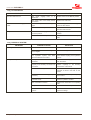
3_TECHNICAL DATA
The technical data contained in the following tables are informative therefore we reserve the right to
modify them without obligation to give prior notice.
•
•
•
All the measurements are expressed in millimetres (mm).
All the weights indicated are in kilograms (kg).
The symbol "-" indicates a value lying between a minimum and a maximum.
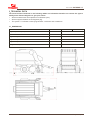
3.1_DIMENSIONS
LT
LTR
LTC
4180
4180
Width La
2520
2520
Height H with tyres: 400-15.5 or 15.0/55-17
2600
2700
Height H with tyres 11.5/80-15.3
2580
2680
Height H with tyres 19.0/45-17
2590
2690
* Length X with ejector
250
250
H
Length Lu (without ejector) *
Lu
La
X
Chapter 3 – p.1
Round baler EXTREME
LT
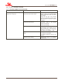
3.2_WEIGHTS
FEEDER
LT
Binding
Twine
Net
Twine/Net
Pick-up LT M
2410
2510
2550
Pick-up LT L
2440
2540
2580
ROTARY FEEDER
LTR
Binding
Twine
Net
Twine/Net
Pick-up LT M
2800
2900
3040
Pick-up LT L
2830
2930
3070
CUT 13
LTC
Binding
Twine
Net
Twine/Net
Pick-up LT M
2910
3010
3050
Pick-up LT L
3020
3040
3090
LTR
LTC
ADDITIONAL WEIGHTS
LT
Ejector
Cardan shaft 3600120
52
25
Cardan shaft 3600076
Cardan shaft 3600049
Chapter 3 – p.2
25
25
Round baler EXTREME
LT
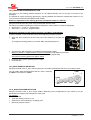
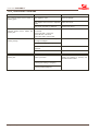
3.3_PICK-UP UNIT AND TRANSPORT ASSEMBLY
PICK-UP
M
L
Max. collection width
1725
2000
Width between tines
1593
1869
Pitch between tines
69
Roll-holder diameter
250
N°. bars for roll-holder
4
N°. tines for bar
24
28
N°. of overall tines
96
112
Support wheels
fixed
Dimensions of wheels /n° wrappers
16.650/10
Adjustment of working height
mechanical 13 positions
CONVEYING UNIT
FEEDER
N°. of tines
16
Pitch between tines
69
CUT 13
N°. of knives
13
Pitch between knives
77
Knives control
electric
Protection of knives
simple, spring-type
Feeding rotor
3-point star
3.4_BINDING
TWINE
Twine binder
Yarn count of twine
Twine skeins
NET
Double wire
500÷1000
n°.6
Reel diameter net
250÷300mm
Yarn count of net
12÷16 g/m
Plastic film
Command
Max n. of conveyable reels (with single binder)
Max n. of conveyable reels
FILM
--electronic
electronic
12
3
3
wire = 12
wire + net = 6+1
3
3
Chapter 3 – p.3
Round baler EXTREME
LT
3.5_BELTS
Belts for machine
5
Width
218
Length
10470
Fasteners
MATO U24BS n°.17
3.6_TYRES
Ply
Index radius
(mm)
Speed
(km/h)
Wheel capacity
(kg)
Pressure
(bar)
External
diameter (mm)
Series:
400/60-15.5
10-14 P.R.
380
40
2240÷2745
2,5÷3,5
875
Option:
15.0/55-17
12-14 P.R.
410
40
2083÷2300
3,1÷3,7
850
11.5/80-15.3
12-14 P.R.
410
40
1930÷2187
4,1÷4,75
845
19.0/45-17*
10-14 P.R.
390
40
2124÷2800
2,25÷4,0
850
3.7_CARDAN SHAFTS
LT
LTR
Series:
3600120
BYPY 654 (OC+FV42 1350Nm)
Option:
3600049
BYPY 656 (OC+SB6)
LTC
3600076
BYPY 656 (OC+SB6)
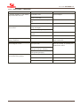
3.8_TRACTOR REQUIREMENTS *
LT
PTO speed
Required power minimum kw-cv
Hydraulic system
Necessary oil flow rate
Electric system
Speed transport by road max.
LTR
LTC
540 rpm
45÷60
58÷80
n°.1 double-acting distributor
+ n°.1 single-acting distributor
25 liter/1'
12V= / negative mass
40km/h
(*) With tractor having a cabin: if a tractor without the cabin is used, ask the FERABOLI company for the special "ZMP2015 - Hydraulic
Line Protection Extreme”.
3.9_CHARACTERISTICS OF THE BALE
Diameter
Width
500÷1650
1200
Weight of hay bale
300÷625
Weight of straw bale
280÷420
Weight of grass bale
600÷1235
Hourly production
Chapter 3 – p.4
25÷45
Round baler EXTREME
LT
3.10_FEATURES OF THE “F_bus” CONTROL SYSTEM
QuickTronic
EasyTronic
Power supply
11÷15 V Dc
11÷15 V Dc
Controls: membrane keyboard
23 keys
9 keys
Display
LED
Graphic LCD: 128x64 pixel
Back lighting
White LED
Microprocessor
16 bit 24Mhz
16bit 24Mhz
Memories
Flash + Static RAM + Eeprom
Flash + Static RAM + Eeprom
Buzzer
Buzzer
Internal Buzzer
Degree of protection
IP 54
IP 65
Operating temperature
0÷50
0÷50
Storage temperature
-10÷70
-10÷70
Relative humidity
100%
100%
Vibration test (x-y-z per 1hr)
20÷50Hz → 1.0G/51÷300Hz → 0.5G
20÷50Hz → 1.0G/51÷300Hz → 0.5G
Container
Aluminium + steel
ABS
Colour
Black
Black
Method of fastening
Bracket
Magnet
Overall size (max.)
165x 142x 48
190x 105x 90
Weight
750g
420g
Conforming to CE regulations
Yes
Yes
MODULES (sensors, motor controls, etc.)
Power supply
11÷15 V Dc
Degree of protection
IP 65
Operating temperature
-20÷70
Storage temperature
-30÷80
Relative humidity
100%
Vibration test (x-y-z for 1hr)
20÷50Hz → 1.0G/51÷300Hz → 0.5G
Conforming to CE regulations
Yes
Chapter 3 – p.5
Round baler EXTREME
Chapter 3 – p.6
LT
Round baler EXTREME
LT
4_GENERAL SAFETY REGULATIONS
In addition to the regulations contained in this operator's manual, observe the general regulations for safety
and accident prevention in force in your Country.
This machine has been designed and manufactured for the maximum safety at work. Maintenance of these
safety conditions is obligatory for the user.
Therefore, read this manual very carefully especially the safety regulations and with great attention to those
operations that are potentially very dangerous; if you do this while working it will be too late!
FERABOLI S.p.A. declines all and any liability for failure to observe the safety and accident prevention
regulations provided in this manual.
All and every liability for damage caused by the improper use of the round baler or modifications made
without authorisation is also declined.
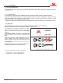
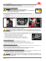
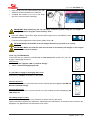
4.1_TERMINOLOGY ADOPTED
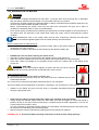
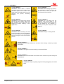
When you see one of the following symbols, read and memorise the message, and inform all the operators.
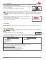
This is the ALERT symbol for personal safety; it indicates a possible situation of
danger.
In this manual all the ALERT personal safety points are shown by this symbol and
associated with a "signal word" which varies depending on the immediacy or potential of
the dangerous event:
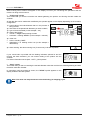
WARNING!:
The word WARNING indicates a potentially dangerous situation that may result in death or serious
injury if not avoided.
CAUTION!:
The word CAUTION indicates a potentially dangerous situation that may result in minor or moderate
injuries if not avoided.
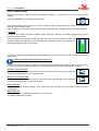
This is the ALERT symbol for protecting mechanical parts; it indicates a possible
situation of danger.
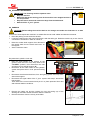
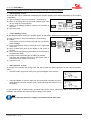
IMPORTANT!:
In association with the word IMPORTANT, warns that if the operations are not
carried out correctly serious damage to the machine may result.
This is a warning symbol for the operator; it reminds the operator to switch off the
tractor and remove the key from the dashboard.
Whenever this symbol is found in the operator's manual, you must switch off the tractor and
remove the key from the dashboard before carrying out the operations described in the
symbol.
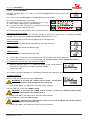
FERABOLI S.p.A. declines all liability for damage due to failure to observe these warnings.
This is a symbol denoting “Note:”
This symbol requires the operator to pay greater attention in reading and memorising the
information given!
Chapter 4 – p.1
Round baler EXTREME
LT
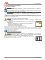
4.2_SAFETY WARNINGS
Before putting the machine into operation:
• Make sure that you have a perfect knowledge of the controls and their functions.
• Conduct a regular check of the perfect condition of the entire machine: all the safety and protection
devices.
• All the accident prevention protection guards must be mounted and fixed in accordance with the
manufacturer's instructions and must not be tampered with.
WARNING! It is absolutely forbidden for the round baler to be used by persons who have not
read and assimilated the contents of this manual.
4.2.1_WARNINGS TO THE INDIVIDUAL
Pay attention to the danger symbols shown in this manual and on the machine itself; the adhesive danger
signs must always be clearly visible.
• Make sure that they are always kept clean and replace them if they have deteriorated or are difficult to
read.
•
You will find the position and the list of all the danger signs in the paragraph “4.4_ Adhesive safety signs”.
WARNING!
CAUTION!
•
•
•
Never leave the machine unattended during work.
Never leave the tractor unattended with its engine running.
Do not allow the machine to be used by minors or persons who are not competent, or not in good
health or who do not have a valid driving license.
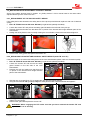
•
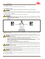
The radius of action of the machine is to be considered a dangerous area: before
putting the machine into operation make sure that there are no persons or animals
around the work area, otherwise stop the machine and clear the area.
The person using the round baler is liable towards third parties for any damage caused
by the machine inside the radius of action.
During operation of the machine it is absolutely forbidden to approach the mechanical parts, touch the
moving parts or interpose oneself between them.
Keep your face, hands and feet away from moving parts; stay at a safe distance.
•
Do not stand behind the machine, the tailgate may be open and the bale may be
ejected.
•
The area in front of the pick-up is very dangerous; when the machine is in operation, never introduce the
forage using the hands, feet or the help of any other object.
CAUTION! In the event of product accumulation in the feed zone:
• Stop the tractor, remove the keys from the dashboard and wait for all the
moving parts of the machine to stop completely.
• Switch off the “F_bus” system.
•
Follow the instructions shown in the paragraph “8.7_Unblockage of the product”.
Chapter 4 – p.2
Round baler EXTREME
•
•
•
•
•
•
LT
Load the twine or net wrap only with the tractor engine off, and after cutting off the current to the “F_bus”
control unit.
Do not use the controls, tubes and other protruding parts of the machine to hang things on.
Assemble, operate and detach the cardan shaft always respecting the information and safety rules for use
of the cardan shaft contained in the booklet provided by the manufacturer of the cardan shaft and
delivered together with it.
It is absolutely forbidden to transport persons or animals on the machine or tractor.
During maintenance and/or repair work it is obligatory to wear protective clothing, cut
resistant gloves, safety footwear and goggles.
Do not wear clothes that could get caught on the moving parts. If there is a risk of
objects being thrown out, wear a protective helmet fitted with a visor.
For further information consult the paragraph “4.6_Clothing”.
•
Take great care to maintain a minimum safety distance when operating in the vicinity of
electrical power lines; the machine is made mainly of metal and therefore if it comes into
contact with an electrical line or if there is a discharge between the line and the machine
the operator could be electrocuted with possible fatal consequences.
If it is necessary to operate in the vicinity of electrical transmission lines contact the
competent electricity company.
•
Unload the bales on flat ground or in a suitable position if the ground is sloping.
•
High pressure hydraulic oil can penetrate the skin and cause serious injury. Before
detaching any tubes or doing any checks the system should always be depressurised.
If any hydraulic oil under pressure should penetrate the skin go immediately to hospital
otherwise there is a serious risk of infection.
FERABOLI S.p.A. declines all liability resulting from failure to observe these safety warnings.
Chapter 4 – p.3
Round baler EXTREME
LT
4.2.2_WARNINGS FOR THE MACHINE
WARNING!
CAUTION!
•
The hydraulic couplings shall always be kept clean. To prevent them from becoming dirty or damaged,
after use always refit the protective plastic cover provided at the time of purchase.
Check and if necessary replace any damaged tubes or fittings; all flexible tubes should be replaced in any
case five years after the date stamped on the tube.
Before re-pressurising the system check that the tubes and connections are tight; use a piece of
cardboard or absorbent paper to check for possible leaks.
•
Each cardan shaft is provided with an operating and maintenance manual supplied by the manufacturer of
the cardan shaft. The protection of the cardan shaft, tubes and covers must be mounted and in perfect
condition.
Note: Maintenance work on the cardan shaft must be done scrupulously following the instructions
given in the booklet supplied together with the cardan shaft by the manufacturer.
Before inserting the PTO make sure that:
• the number of turns corresponds to the required number (refer to the decal located on
the steering bar of the machine).
• the direction of rotation is the same as that indicated by the adhesive safety sign.
•
•
•
•
NEVER insert the PTO before starting the tractor motor.
Stop the PTO during the turns at the end of the swathes and any other tight turns.
When the machine is detached from the tractor position the cardan shaft on the special support.
Never start a bale if the tailgate is not completely closed; check this condition also on the display of the
control unit.
WARNING!: FIRE RISK
Remove the accumulated product regularly to reduce the risk of fire and to prevent
material from winding around the mechanical parts of the machine.
If the bale should catch fire:
1) Immediately expel the bale and keep the tailgate open.
2) Move the tractor and machine away from the product still to be collected and any other
inflammable material.
3) Put the fire out using the extinguisher, advised as part of your equipment.
There must always be an extinguisher on the tractor, especially if you are working on a dry product.
•
Repairs to the wheels and tyres must be done by competent specialised personnel
having the appropriate tools.
•
Never drive on public or private roads with a bale in the chamber of the round baler.
Always empty the chamber before leaving the field. Make sure that the tailgate is closed and locked in
position. Driving on the open road must be done in compliance with the traffic regulations in force in the
Country where the machine is used.
It is very important to remember that the capacity for road holding, maintaining direction and braking may
be influenced considerably by the load being towed.
Before towing the machine withdraw the parking jack into the position for transport.
•
FERABOLI S.p.A. declines all liability resulting from failure to observe these safety warnings.
Chapter 4 – p.4
Round baler EXTREME
LT
4.3_MAINTENANCE IN SAFETY
WARNING!
IMPORTANT!
Before making any adjustments or doing any maintenance, service or repair work and before leaving
the machine unattended, take the following precautions:
1)
2)
3)
4)
5)
Stop the machine and detach the PTO.
Rest the pick-up on the ground.
Always turn off the tractor motor and remove the keys; apply the handbrake.
Ensure that all the moving parts of the machine have been stopped completely
Switch off the “F_bus” system
•
It is absolutely forbidden to remove or tamper with the safety devices because these have been designed
and installed for your protection and safeguard. If they should get damaged replace them before using the
round baler again.
Check frequently that the nuts, screws and bolts are correctly tightened.
Check frequently and regularly the state of wear of the bearings, rollers, chains and gears.
•
•
Do not carry out any maintenance or cleaning work if the tractor has not been turned off first and the keys
removed from the dashboard.
Remove any dirt that might have accumulated from all the moving parts of the machine.
•
Do not use high pressure jets for cleaning the machine; this may cause serious damage
to the mechanical parts.
•
•
Take careful note of the precautions to be taken for welding work.
Detach the machine from the tractor, remove any residual forage and make sure that
there are no plastic materials nearby in order to avoid fire risk.
•
It would be advisable to have a fire extinguisher at hand just in case.
•
Use the oils advised.
•
Carry out the maintenance scrupulously according to this manual and have worn or
damaged parts replaced by specialised personnel.
USE ORIGINAL SPARE PARTS ONLY.
•
•
Spare parts must correspond to the requirements established by the manufacturer.
Use only the cardan shafts indicated by the manufacturer of the machine.
The table below shows the maximum values on the towing eye depending on the machine model:
MAX VALUES ON TOWING EYE (kg)
LT
Load
LTR
460
LTC
490
WARNING! This operator manual with instructions for using the round baler must be read
memorised and kept for the entire life of the machine.
FERABOLI S.p.A. declines all liability deriving from failure to observe these warnings.
Chapter 4 – p.5
Round baler EXTREME
LT
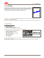
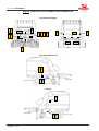
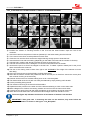
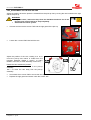
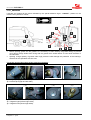
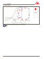
Diagram: LOCATION OF PICTOGRAMS ON THE ROUND BALER
* only with net wrapper
1
2
12*
16
5
15
4
7 8 9 11
7
13
3
* only mod.LTR and LTC
12* 6*
6 10
* internal
6*
6 10
Chapter 4 – p.6
14
4
Round baler EXTREME
LT
4.4_SAFETY SIGNS
Adhesive signs have been affixed to the machine containing important messages regarding personal safety.
Their purpose is to call the operators attention to the health and safety at work rules and warn against possible
dangerous situations during work and maintenance.
• The safety signs typically have black and red pictograms on a yellow background.
• They must always be kept clean and legible and must be replaced whenever damaged or peeling off.
• If the parts of the machine to which they are affixed are replaced or painted they must be replaced as
before.
For this purpose each adhesive sign bears a code number so that it may be ordered from the Spare Parts
Service. Ask the Spare Parts Service for these adhesive signs quoting the relative codes.
To obtain the complete series of adhesive safety signs for the Extreme round baler ask our spare Parts
Service quoting the relevant code number:
• 7Z00648 “CE Safety decal - Extreme mod.LT”
• 7Z00649 “CE Safety decal - Extreme mod.LTR and LTC”
All the adhesive safety signs present on the round baler are illustrated and described on the following pages
and represented in the diagram: “Location of pictograms on the round baler”.
Read carefully the meaning of the signs and inform your co-workers and whoever may approach the machine
during work and maintenance.
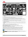
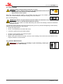
4.4.1_PICTOGRAMS
This is the description of the adhesive safety signs placed on the machine and represented in the diagram
“Location of the pictograms on the round baler”, shown on the previous page:
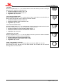
1) cod. 7500185-1
CAUTION! Before putting into service,
at the beginning of each season and
before doing any work on the machine,
read and bear in mind the instructions
for use and maintenance given in this
operator manual.
2) cod. 7500186-1
CAUTION! Before doing any repair or
maintenance work on the machine,
turn off the tractor motor, remove the
keys from the dashboard and read the
operator manual.
3) cod. 7500187-1
CAUTION! Machine suitable for
tractors with power take-off at 540 rpm
and one direction of rotation.
4) cod. 7500198-1
WARNING! Do not pass by or stand
under the tailgate when it is raised to
avoid being crushed if the special
safety locks have not been applied.
5) cod. 7500199-1
WARNING! Do not enter the
manoeuvring space between the
machine and the tractor when the
motor is running. This area is
particularly dangerous.
6) cod. 7500203-1
WARNING! Before doing any work
wait until all the parts of the machine
are
completely
still
and
use
appropriate methods to block any
undesired movements.
Chapter 4 – p.7
Round baler EXTREME
LT
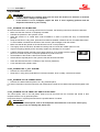
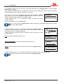
7) cod. 7500207-1
WARNING! Never feed or remove
material by hand in front of the pick-up
unit when parts are in motion. This
could result in the upper limbs, or more
seriously the person, becoming
trapped.
8) cod. 7500208-1
WARNING! Before doing any work on
the hydraulic system consult the
operator manual. Oil under pressure
can cause serious infections.
9) cod. 7500210-1
WARNING! Do not remove the guards
and do not touch parts, which may
also suddenly move under their own
weight and cause crushing of the
upper limbs.
10) cod. 7500221-1
WARNING! Do not stand near the
machine. This could result in the
crushing or cutting of lower limbs due
to the weight of the machine or
lowering of its parts. Keep at a safe
distance.
11) cod. 7500724
WARNING! Before entering the bale
forming chamber to do any operations
or for other reasons, lock the hydraulic
jacks by turning the valve to the closed
position.
12) cod. 7500726
WARNING! Danger of cutting hands.
13) cod. 7500197-1
WARNING! Do not stand behind the machine. Risk of being crushed by sudden
movements.
14) cod. 7500201-1
WARNING! Take great care when working near electrical lines.
15) cod. 7500212-1
WARNING! Do not stand behind the machine when the bale is ejected. Keep at a
safe distance.
16) cod. 7500781
WARNING! Danger of getting caught and being dragged by the cardan
shaft.
Chapter 4 – p.8
Round baler EXTREME
LT
4.4.2_REFLECTORS
Two types of reflex reflectors are located on the
round baler so that it can be seen more clearly
during road transport:
R) Round reflectors (front).
T) Triangular reflectors (rear).
R
R T
front
T
rear
4.4.3_CARDAN SHAFT DECAL
An adhesive sign is affixed to the cardan shaft to draw the operator's attention and remind
him/her of the safety rules for using the cardan shaft.
Chapter 4 – p.9
Round baler EXTREME
LT
4.5_SAFETY DEVICES
The machine is provided with safety devices in order to ensure a more correct use without risks in normal
working conditions.
WARNING! Before starting work make sure that all the safety devices are intact and in place.
4.5.1_PROTECTION GUARDS
The machine is provided with protection guards to protect the operator from moving mechanical parts and to
protect the parts from accidental entry of foreign bodies:
4
6
9
3
3
5
10
7
7
2
11
1)
2)
3)
4)
5)
6)
7)
8)
9)
10)
11)
8
1
2
Protection guard of the deviation box.
Protection guard of the shafts.
Pick-up protection guard (right and left).
Pick-up safety protection guard (mod.LT)
Protection guard of the pick-up unit (left side).
Protection guard of the large roller.
Side covers.
Tailgate rear protection guards to protect the belts.
Protection guard (mod.LTR and LTC)
Front protection guard to protect the belts.
Protective covers of the cardan shaft /transmission box.
The lateral gull-wing door protection guards are provided with a safety lock that ensures perfect closing of the
protection guard with the machine and thus prevents accidental opening during work or transport.
• To open the protection guards a 13mm spanner is required.
WARNING! Before removing any of the protection guards:
• Stop the machine.
• Turn off the tractor and remove the keys from the tractor dashboard.
Chapter 4 – p.10
Round baler EXTREME
LT
4.5.2_CARDAN SHAFT SAFETY
Each cardan shaft is provided with a safety system to protect the mechanical parts from high pickup voltage
torques and maximum twisting moments:
•
•
•
“FV” = with clutch torque limiter.
“SB” = with shear bolt.
“LR” = with automatic torque limiter.
FV
SB
LR
4.5.3_PICK-UP TRANSMISSION SAFETY
The pick-up transmission is provided with a shear
bolt torque limiter against overloads and foreign
bodies.
4.5.4_MECHANICAL TRANSMISSION SAFETY DEVICE (mod.LTR and LTC)
The drive transmission to the cutter is provided with
a shear bolt torque limiter against overloads and
foreign bodies.
4.5.5_AUTOMATIC TRANSMISSION SAFETY DEVICE "AFC" (optional - mod.LTR and LTC)
On machines provided with a cutting system it is
possible to install an automatic overload control
system called "AFC" on the shaft coming out of the
transmission box towards the feed rotor.
This device interrupts power transmission when there is an overload in order to prevent damage to the
machine, the cardan shaft and the tractor.
The "AFC" automatic limiter does the same job as the safety bolt with the advantage that it does not require
the replacement of the sheared bolt and allows the power to be re-engaged automatically.
4.5.6_BLADES (mod.LTC)
As protection against the entry of foreign bodies into the machine (stones, sticks,
etc.) that may cause the blades to break, each blade is mounted on a retractable
spring system that allows the blade to lower automatically and then to return
automatically to the work position.
Chapter 4 – p.11
Round baler EXTREME
LT
4.5.7_BLADE SECURING SAFETY DEVICE (mod.LTC)
The handle “M” secures the blades of the cutting
system during operation to prevent them from
accidentally entering the bale forming chamber.
• Position "1" = blades secured.
• Position "2" = blades free.
(1)
M
(2)
M
4.5.8_CARDAN SHAFT SUPPORT
A) This is for the cardan shaft to rest on when it is not connected to the tractor
and thus to protect it from damage.
4.5.9_CARDAN SHAFT SAFETY CHAIN
B) This prevents the rotation of the cardan shaft protection guards during work.
Attach it to the steering bar.
4.5.10_SUPPORTS AND CONDUIT GUIDES
These support hydraulic tubes, electrical cables and wiring.
4.5.11_PARKING CHOCKS
These are place under the tyres to block the
machine and prevent any accidental movements
when not in use and whenever it is necessary to
immobilise the machine for repairs, maintenance or
cleaning.
Chapter 4 – p.12
A
B
Round baler EXTREME
LT
4.5.12_TAILGATE SAFETY LOCK DEVICE
There is a safety device to lock the tailgate in the
open position thus avoiding accidental closing when
the operator is inside the machine for maintenance
or repair work.
• With the door open, turn lever "L" towards the
red arrow, to the stopped position (lock closed),
as shown in the figure
L
IMPORTANT! Remember to disengage the tailgate safety device by turning the lever to its
original position before closing the tailgate.
4.6_CLOTHING
•
•
During work wear suitable clothing
never wear baggy clothes that flap as these could get caught in the mechanisms and
moving parts of the machine.
•
Long hair must be gathered.
During maintenance and repairs it is obligatory to use protection gear such as:
• cut resistant gloves,
• safety footwear,
• goggles.
Dust or substances harmful to the respiration may be produced during work or maintenance.
It is advisable to use suitable personal protection equipment
4.7_SOUND LEVELS
CAUTION! Observe the regulations in force in your Country regarding the
acoustic protection to be used.
In some circumstances the noise level produced may exceed 85dbA÷90dbA. In these cases
it is advisable to use suitable personal protection equipment.
85dbA÷90dbA
4.8_ECOLOGY AND POLLUTION
CAUTION! Respect the laws in force in your Country regarding the use and disposal of
products used in the operation, maintenance and cleaning of the machine.
•
•
Whenever you drain oil from the various mechanical parts and hydraulic system and any other substance
toxic and/or dangerous to the environment try to avoid leaks.
Keep these substances in a safe place until they can be disposed of correctly according to the regulations
in force and availability of special disposal facilities.
Dispose of any residual packing materials of the machine in the special containers for separate rubbish. If
the machine is scrapped observe the anti-pollution laws of your Country.
Chapter 4 – p.13
Round baler EXTREME
Chapter 4 – p.14
LT
Round baler EXTREME
LT
5_TRANSPORT AND HANDLING
WARNING!:
• Never use the machine as a means of transport for things and/or people.
• It is strictly forbidden to tow the round baler with bales on board.
• Do not operate the round baler when it is being towed
The machine must be towed as follows:
• Machine unloaded.
• All components in position for transport.
• All safety devices engaged.
•
•
•
The round baler can be towed on the roads by a tractor at a speed not exceeding 40Km/h.
The machine is hooked onto the rear hook of the tractor using the towing eye attached to the front steering
bar of the round baler with the special towing rod and safety pin “7.2_Hook up to the tractor for towing”.
Connect the electrical system and check that all the indicator, parking and stop lights are working
correctly.
Before towing:
• Raise the pick-up to the transport position (all the way up) and close the valve (closed position,
“7.4.3_Connection of the hydraulic system”).
• Raise the rest foot to the transport position, “7.2_Hook up to the tractor for towing”.
• Do not connect the quick release couplings of the round baler to the tractor.
• During transport the cardan shaft is disconnected from the tractor and must be secured to the steering
bar.
• If it is necessary to tow the machine over a long distance it may be loaded on a lorry or railway cars.
Chapter 5 – p.1
Round baler EXTREME
LT
5.1_LOADING BY RAMP
It is forbidden to use ramps for loading and unloading the machine.
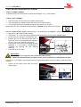
5.2_LOADING BY CRANE
WARNING! Before raising the machine make sure that it does not contain any bales.
To raise the machine from the ground to the loading level, if there are no loading ramps available, use a crane
of sufficient capacity; make sure that you have a crane and a load equalising arm of suitable capacity for
raising the machine “3.2_Weights”.
Use of all four points of attachment for correct safe loading is compulsory.
IMPORTANT!
• The four attachment points for raising the machine are clearly visible and marked with
special adhesives code 7500216.
• Attach the machine only at the four points indicated by the adhesive signs to avoid
damage.
n°.4
FERABOLI S.p.A. declines all liability arising from damage to the round baler caused by incorrect
attachment for lifting.
Raise the machine with extreme care and move it slowly, without jerking, onto the lorry or railway car.
WARNING! Raising and transporting the machine can be very dangerous if not done with the
greatest of care, therefore:
• Make sure that the means available are in good working order and suitable for the load.
• Clear and cordon off the area in which transferral is to take place.
• Make sure that the area in which you are working has been cleared and there is an escape
route, i.e. sufficient space to move out of the way quickly should the load fall.
• Keep onlookers at a distance.
• Do not touch suspended loads and remain at a safe distance.
• During transport the loads must not be raised more than 20 centimetres above the ground.
CAUTION! The level on which it is intended to load the machine must be perfectly flat to avoid
possible shifting of the load.
Once the machine has been loaded on the lorry or railway car it is necessary to secure it to the surface on
which it stands with cables or chains using the same attachment points and anchoring points located on the
same surface and to block the wheels with the chocks.
CAUTION! Make sure that there are no parts of the machine protruding beyond the maximum
overall dimensions permitted by the transport.
After transport and before detaching the machine from all its attachments, make sure that its state and position
do not constitute a danger.
Then remove the packing and proceed with unloading using the same equipment, methods, attention and care
as in the loading operations.
Chapter 5 – p.2
Round baler EXTREME
LT
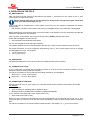
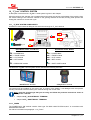
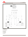
6_GENERAL DESCRIPTION
The round baler carries out the following operations:
• Gathering of forage already cut in swathes
• Pressing into a cylindrical shape (bale)
• Bale binding
• Ejection of the bale onto the ground
The machine consists of a structure mounted on a frame, including all the working parts, supported on an axle
with wheels for movement and has a steering bar with a hook up to the tractor.
The electrical system controls the control unit and lighting system for road transport.
The hydraulic system is driven by coupling the connection tubes of the round baler to the single and double
action connection fittings on the tractor.
A cardan shaft connected to the tractor and the transmission box on the machine transmits movement to all
the moving parts.
f
f
d
f
9
7
5
4
f
6
8
b
f
c
3
f
f
c
13
a
1
10
e
2
11
12
6.1_MAIN COMPONENTS OF THE ROUND BALER
1)
2)
3)
4)
5)
6)
7)
8)
9)
10)
11)
12)
•
•
•
13)
Steering bar
Parking jack
Cardan shaft
Deviation box
Net wrapper
Twine binder
Belts
Primary belt stretcher
Terminal of “F_bus” control system
Tailgate
Pick-up
Transport unit
Feeder (mod.LT)
Rotary feeder (mod.LTR)
CUT 13 (mod.LTC)
Ejector
a)
b)
c)
d)
e)
f)
Large roller
Motor smooth roller
Wing rollers
Rubberized roller
Tailgate idler roller
Idler rollers
Chapter 6 – p.1
Round baler EXTREME
LT
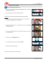
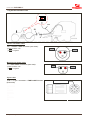
6.2_DESCRIPTION OF THE WORK PROCESS
The pick-up gathers the forage ready for collection in
the swathes and, with the help of the side aprons
and the two screw feeders on the sides, the forage is
gathered into a band of width corresponding to that
of the gathering chamber.
An oscillating comb (round baler mod.LT), or a rotor
(round baler mod.LTR), or a cutting unit with rotor
and blades (round baler mod.LTC) transport the
product in the compressing chamber.
Here, by means of belts and rollers, the core of the
bale is formed.
When the desired size is reached, adjustable to a
minimum of 0.51m up to a maximum of 1.65m, the
automatic binding/wrapping system comes into
action tying the bale with double twine or wrapping it
with net and is controlled by the “F_bus” system.
The bale is ejected by hydraulic command from the
tractor without disengaging the power take-off.
An ejector makes sure that the bale is moved out of
the radius of the tailgate's closing movement.
The round baler has various possibilities for adjustment of the diameter and density of the core of the bale,
which are determined on the basis of the type of forage and your process needs.
It is possible to start the bale with a harder or softer bale core by means of electronic selection.
Chapter 6 – p.2
Round baler EXTREME
LT
7_INSTRUCTIONS FOR USE
7.1_BEFORE USE
Note: All operations are to be carried out by a single operator who must have read and
understood all the parts of this manual, especially the section on safety.
Before starting work, make sure that the machine is in order, that the lubricants are at the right level and that
all the parts subject to wear and deterioration are working perfectly.
WARNING! Adjustments and preparations for work must be done with:
•
•
•
The tractor switched off and the keys removed from the dashboard.
The machine switched off and blocked.
Switch off the “F_bus” system.
(unless there are specific instructions to the contrary in this operator manual).
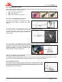
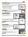
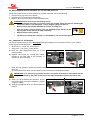
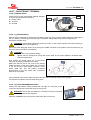
7.2_HOOK UP TO THE TRACTOR FOR TOWING
CAUTION! Hooking up to the tractor can be dangerous therefore take great care in this
operation.
Use a tractor that is suitable for towing the machine in use “3.8_Tractor requirements”.
Make sure that there are no objects resting on the machine and that there are no persons and/or animals in
the immediate vicinity.
The steering bar of the round baler is provided with a pivoting towing eye.
•
•
•
•
•
•
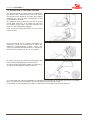
Hook up the round baler to the rear hook of the
tractor making sure that the machine is in a
stable horizontal position and that the towing eye
is at the same height as the towing device of the
tractor.
Rotate the handle "M" of the parking jack to
lower or raise the towing eye until it is correctly
aligned with the tractor's towing device.
Insert the pin in the towing eye and secure it with
the safety pin; then raise the parking jack "P", by
turning again the handle “M”.
M
P
Then remove any chocks from under the wheels.
Insert the feeder plug of the lighting system for road transport of the round baler into the socket of the
tractor and check that all the indicator, parking and stop lights are working correctly.
Make sure that the tailgate and the protection guards are closed properly and secured.
•
Retract the parking jack "P" into the towing
position and secure it with the special spring.
•
Make sure that the pick-up is in a high position.
Chapter 7 – p.1
Round baler EXTREME
LT
7.3_HOOK UP TO THE TRACTOR FOR WORK
Before connecting any of the various components of the baler to the tractor, make sure that the tractor meets
the requirements for the correct working of the round baler “3.8_Tractor requirements”.
The steering bar of the round baler can be adapted to the tractors towing device which may be of the
“standard” or “high” type.
In any case the towing eye must always be parallel with the ground.
WARNING! Adaptation of the drawbar to the attachment of the tractor must always be done
with:
•
•
•
•
•
The tractor switched off and the keys removed from the dashboard.
Machine taken off the tractor.
Servo drawbar placed on the soil.
Machine locked on stable soil, in order to prevent any possible accidental
shifts of the machine.
Switch off the “F_bus” system
Keep in mind all the basic safety rules contained in the chapter “4_General safety regulations”.
7.3.1_”STANDARD” HOOK UP
160÷290
max. 300
450
The machines leave FERABOLI S.p.A. with the
hook up for the tractor in the “standard”
configuration.
If necessary it is permissible to use an extension
"P" for hooking up to your tractor within the limits
shown in the figure.
P
Chapter 7 – p.2
Round baler EXTREME
LT
7.3.2_HIGH HOOK UP
It is also possible to connect the round baler to tractors having a "high" towing device, within the limits
allowed, as shown in the figure.
In order to do this it is necessary to adapt the steering bar of the round baler to the hook up of the tractor:
V1
max. 200
•
•
•
•
•
F
800÷1050
min. 200
F
V2
Remove the two plugs "F" located at the end of the steering bar and unscrew the screws "V1" that fix the
towing eye and the two screws "V2" that fix the wings of the steering bar to the cross-bar of the machine.
Rotate the steering bar to the position for the 'high' hook up of the tractor and, at the same time, keep the
towing eye parallel with the ground in the same way.
Once the right adjustment is obtained, check the correct coupling of the toothed fifth wheels
before tightening the screws.
Then tighten the screws "V1" and "V2" taking great care to keep to the torque value of 700Nm.
Re-close the end of the steering bar with the two plugs “F”.
IMPORTANT! It is permitted to use the high hook up with a measurement of 800÷1050mm
Chapter 7 – p.3
Round baler EXTREME
LT
7.4_CONNECTION OF VARIOUS DEVICES OF THE ROUND BALER
After completing the hooking up of the round baler to the towing device of the tractor “7.2_Hook up to the
tractor for towing”, retract the parking jack to the rest position.
Then continue with the connection of the various devices of the round baler:
• Connection of the “F_bus” system
• Connection of the lighting system
• Connection of the hydraulic system.
• Attachment of the cardan shaft.
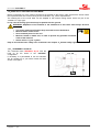
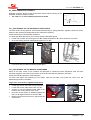
7.4.1_CONNECTION OF THE "F_bus" CONTROL SYSTEM
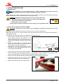
When you connect the machine to the tractor for the first time you must first connect the power cable "A" to
the battery "b" 12V= of the tractor.
IMPORTANT! Be careful not to invert the polarity:
• RED cable "+" pole (positive)
• BLACK cable "-" pole (negative)
•
This must be done with the tractor off.
The electrical circuit of the round baler requires a supply current with negative earth 12V=
The plug "S1" of the battery feed cable must be positioned behind the tractor.
Install the terminal in the tractor cabin so that it is clearly visible and within the reach of the operator
• Position the terminal "T" correctly in the tractor cabin.
• Connect the current cable "C", outside the machine.
• Connect the signal cable "CS", in the tractor cabin”.
Check that the terminal has come on by pressing the appropriate key; if the cables have been connected
correctly, the system will come on.
T
S1
S1
A
b
C
7.4.2_CONNECTION OF THE LIGHTING SYSTEM
Connect the lighting system and check that all the indicator, parking and stop lights are working correctly.
Do not insert unsuitable fuses, do not modify the cables and do not replace plugs and sockets that are not in
conformity with the originals.
For any maintenance and/or repair work contact our Assistance Centre
FERABOLI S.p.A. declines all liability resulting from failure to observe these warnings.
Chapter 7 – p.4
Round baler EXTREME
LT
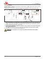
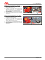
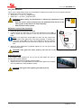
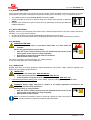
7.4.3_CONNECTION OF THE HYDRAULIC SYSTEM
Connect the hydraulic tubes:
• The small tube is connected to a single-acting
distributor.
• The two large tubes are connected to a doubleacting distributor.
• The small tube for hydraulic raising of the pickup is provided with a stop valve.
Before lifting the pick-up:
• Position the stop valve lever in the "OPEN"
position and then lift it (transport position).
• Finally turn the lever of the valve to the
"CLOSED" position to block it.
CLOSED
OPEN
IMPORTANT! Do not reverse with the small pivoting wheels of the pick up resting on the
ground.
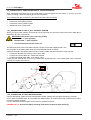
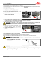
7.4.4_ATTACHMENT OF THE CARDAN SHAFT
The cardan shaft is a transmission device (machine), having "CE" certification.
Each cardan shaft is provided with a user manual; follow and respect all the information and safety rules for
using the cardan shaft contained in this manual scrupulously.
Mount the cardan shaft, provided with the machine,
between the power take-off of the tractor and the
transmission box of the machine; the connection of
the cardan shaft on the tractor side is indicated on
the cardan shaft itself.
Make sure that the length never exceeds the
minimum distance between the machine and the
tractor (cambering hazard), while at the greatest
distance the two tubes must insert one into the other
by at least 1/3 of their length.
1/3
1/3
1/3
1/3
•
•
•
Check that the safety buttons or screws are inserted well into the grooves of the power take-off and
check that the guard rotates freely; if this is not the case apply grease.
Fix the chain to prevent self-rotation of itself and the guard.
For further information on the use and maintenance of the cardan shaft read the special instruction booklet
provided with it.
WARNING! After all maintenance work on the cardan shaft replace the protective covers on the
cardan shaft.
Chapter 7 – p.5
Round baler EXTREME
LT
7.5_OPERATING TESTS
CAUTION! The round baler is always attached to the tractor before any operation, whether
empty or containing a bale.
After making the various connections described above:
• Check that the belts are not stuck to the paint of the rollers.
• Start up the tractor without engaging the PTO and check that the various functional movements of the
round baler are working correctly.
• Check that the hydraulic system is working; that the tailgate opens and closes; raise and lower the pick-up
(remember to move the lever of the stop valve to the "OPEN" position in order to be able to raise the pickup).
• Check that the electrical connection to the terminal is working: switch the “F_bus” system on using the
appropriate key.
• Check that the electrical system, indicator, parking and stop lights are working.
• Close the tailgate and operate the PTO.
CAUTION! Before operating the PTO, make sure that there are no persons in the vicinity;
operate carefully the first time making sure that all the mechanical parts and transmission are
working correctly.
Chapter 7 – p.6
Round baler EXTREME
LT
7.6_SETTING THE MACHINE UP FOR WORK
Before starting work make all the necessary adjustments to prepare the machine for your specific work
requirements.
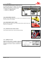
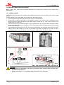
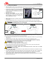
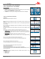
7.6.1_TWINE LOADING
For the twine binder to work well we advise using propylene twine with a yarn count from 500 to 750 or 1000
(m/kg).
The twine binder of your round baler can also work with other types of twine.
• Open the right side guard and place the spools of twine in the special box.
• Connect the six coils to one another in two groups of three (1+2+3 and 4+5+6), by passing the wire
through the slots of the separators (in the BASIC model connect the four coils to one another in two
groups of two (1+2 and 3+4).
• Pass the ends of the two twines through the twine braking device "F1" and pass them completely around
the two rollers "R" (as shown in the figure), which turning during binding, will signal that the twine is being
wound around the bale.
• Then thread the twine through the eyes "O", and then through the two bushings "B" and the two twine
braking devices "F2" located on the arm of the binder; then pass it through the two tubes so that it
protrudes from the other end by about 20cm, as shown in the figure (use one twine per path).
BASIC model
1
2
3
4
1
5
3
6
2
4
R
F1
O
B
F2
B
F2
L
20cm
CAUTION!
• The loading and threading of the twine for binding must be done with the motor and
electronic control unit off.
• Beware of the blade "L" of the binder when doing work in its proximity.
Chapter 7 – p.7
Round baler EXTREME
LT
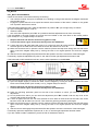
Adjust the tension of the twine on the bale by
loosening or tightening the nuts "d" of the twine
braking device "F1" and "F2":
• Tightening the spring makes the twine tighter.
• Loosening the spring makes the twine looser.
F1
d
F2
d
Your round baler may also be provided with a supplementary twine box which is only for keeping spare twine
so that you do not run out during work in the field.
7.6.2_NET LOADING
•
•
•
The round baler can use spools from 2000 to 3000 metres.
The hole inside the cardboard tube of the roll of net must be 75÷78mm..
For good performance of the binder we advise using a net of 14÷16 (g/m).
WARNING! Switch on the “F_bus” system and, depending on the type of terminal you are
using, follow the instructions for loading the net shown in paragraph:
• QuickTronic = “10-QT.3.3_Net loading”.
• EasyTronic = “10-ET.6.2_Net loading”.
IMPORTANT!
• Take great care to push the net roll onto the tube correctly so that it rotates in the right
direction as shown on the decal
• After positioning the net and before commencing work, bring the net wrapper to its original
position.
• Make sure that the cutter has finished its movement (net wrapper in the original position at
the end of its stroke)
CAUTION! Beware of the blade of the net wrapper when doing any work in its vicinity
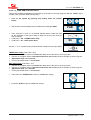
7.6.3_ADJUSTMENT OF THE PICK-UP WHEELS
It is possible to adjust the working height of the pickup:
Raise or lower the height of the pick-up change the
position of the pin "S", located on the support wheel
arm, by inserting it into one of the holes located on
the side of the pick-up to give the working height
required.
S
OPEN
To raise or lower the pick-up:
Use the lever of the tractor switch remembering to
open the stop valve located near the quick release
fitting (position "OPEN").
IMPORTANT!
• The tines of the pick-up must never touch the ground; therefore adjust the working height
of the pick-up so that the tines remain at least 2-3cm above the ground.
• Insert the pin "S" in the same position on both left and right sides of the pick-up.
• Before reversing, the pivoting wheels must be raised from the ground by raising the pickup in order not to damage them.
Chapter 7 – p.8
Round baler EXTREME
LT
7.6.4_RAKE (mod.LT)
Depending on the type of swathe to be collected the rake can be moved to a number of positions:
• Low: for swathes of low volume
• Medium: for voluminous swathes
• High: for very voluminous swathes
With the machine still and the tractor motor off:
• Remove the rake loosening the spring retainers
“Fm”.
• Loosen the screws "V1" of the support brackets.
• Fix the support brackets "S" in the desired
position required for work and screw back the
screws.
V1
Fm
V2
S
IMPORTANT! Position the support brackets "S" in the same position on both left and right
sides of the rake.
• Then remount the rake.
It is also possible to adjust the inclination of the tines by turning the six screws "V2" (3 on each side):
• Loosen and rotate the crosspiece of the rake to the desired position; screw back the six screws “V2”.
IMPORTANT! Check the height of the
inclination "X" of the rake, which must
not exceed 70mm (measurement made
from the feeder grid).
X = max. 70mm
X
7.6.5_FEEDER PLATE (mod.LTR and LTC)
In the machines with a rotor, a feeder plate optimises the collection and channelling of the product into the
baler.
The distance of the plate from the tines of the pick-up can be adjusted by moving the blocks “T”.
With the machine still and the tractor motor off:
• Remove the plate.
• Loosen the screw "V" that secures the block
"T", and position it in one of the holes located on
the side of the pick-up to suit the work to be
done; then screw back the screws “V”.
T
V
IMPORTANT! Position the block "T" in the same position on both the left and right sides of the
pick-up.
• Remount the plate.
For short products and/or swathes of low volume the plate should be close to the pick-up while for tall products
and/or voluminous swathes the plate should be further from the tines of the pick-up.
Chapter 7 – p.9
Round baler EXTREME
LT
7.6.6_CUTTER SYSTEM (mod.LTC)
If your machine is provided with a cutter system, you will have the option of cutting the product while picking
up the swathes.
Using the control terminal, the knives must be engaged in the chamber in order to be able to cut.
WARNING! Switch on the “F_bus” system and, depending on the type of terminal you are
using, follow the instructions for engaging or disengaging the knives as shown in paragraph:
• QuickTronic = “10-QT.3.4_Cutter device”.
• EasyTronic = “10-ET.6.3_Cutter device”.
The cutting length is 77mm
If you wish to cut a longer product it is necessary to remove some of the knives.
Further information regarding the adjustment, replacement and maintenance of the knives can be found in the
paragraph “9.9_Maintenance and adjustment of the cutter”.
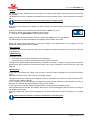
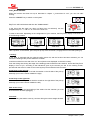
7.6.7_CHOICE OF THE TYPE OF BALE CORE
The choice of the core type varies depending on the machine model your have purchased:
Roundbaler model LT-LTR-LTC:
The “F_bus” system enables you to set the diameter and density of the bale core depending on the forage
type and your working requirements.
• If on the terminal appears “OFF” (off), the machine will work with “hard core”.
• If you set a diameter core value, the machine will work with “soft core”.
Roundbaler model BASIC:
The “F_bus” system allows you to set the max. diameter of the soft core that will be pressed only by the
tension springs.
• If on the terminal appears “OFF” (off), the machine will work with “hard core”.
• The set value is the initial diameter of the pressure.
Chapter 7 – p.10
Round baler EXTREME
LT
7.6.8_OPERATING PRESSURE SELECTION
The choice of the working pressure depends on the desired density and on the type of product to be
packaged.
It is possible to modify the working pressure by choosing between the electronic model (baler model LT-LTRLTC) and the mechanical model (BASIC baler model).
Electronic adjustment of the working pressure (roundbaler model LT-LTR-LTC):
Using the terminal select the value of the pressure with which to work.
For further information regarding the electronic adjustment of the pressure, consult the paragraph:
• QuickTronic = “10-QT.3.1_Programming”.
• EasyTronic = “10-ET.5.1_Program menu”.
Mechanical adjustment of the working pressure (roundbaler model BASIC):
A valve is situated on the round baler which allows adjusting the bale pressure:
•
Open the door located on the front left part of the machine to access the
valve.
To change the working pressure, turn knob “M”, first loosening the nut:
•
Turn the knob “M” clockwise to increase the pressure (heavy bale).
Maximum pressure, of approximately 210 bar, is obtained by fully tightening the knob.
Turn the knob “M” anti-clockwise to decrease the pressure (lighter bale).
The minimum working pressure is approx. 60bar.
•
•
Lock knob "M" in place, tightening the nut again.
Close the door.
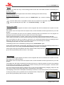
7.6.9_BALE DIAMETER SELECTION
Using the terminal of the “F_bus” control system you can select the diameter with which you intend to work.
You can obtain bales with diameters that vary from a minimum
of 0.50m to a maximum of 1,65m.
1,65m
0,50m
min.
max.
7.6.10_WORK PROGRAM SELECTION
Using the terminal of the “F_bus” control system, depending on the configuration of your machine, you can
personalise the program that manages the work cycle.
For example:
• Bale diameter
• Type and quantity of twine or net
• Automatic or manual binding or wrapping cycle
• Electronic pressure values.
Chapter 7 – p.11
Round baler EXTREME
LT
7.7_FIELD PREPARATION
To ensure the maximum efficiency during collection and baling of the various products we advise operating as
described below:
7.7.1_CONDITIONING
It is important for the forage to be conditioned to ensure uniform humidity content in stems and leaves.
Long stem crops, which are difficult to work with, elastic and tough, must be conditioned in order to break the
stems and reduce their resistance to rolling when the bale is being formed and also because of their
undesirable tendency to get caught between the belts.
To bale maize stalks it is advisable to defibrate for better bale formation and density; do not defibrate too fine!
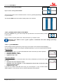
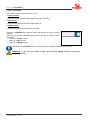
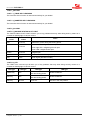
7.7.2_SWATHES
The preparation of the swathes is very important for obtaining a good formation of the bales.
When the forage has been cut and dried the swathes must be formed.
The swathes can be single or double and of width
equal to the width of the pick-up on your machine in
order to make the best use of the round baler's
capacity.
When double swathes are made it is important that
they be left beside each other and not piled into one
heap.
Single swathes can be 0.50÷0.60m wide, but in this
case a “zigzag” guide must be followed in order to
feed the press in a way that takes advantage of the
entire collecting width of the baler and forms a bale
of the right size.
Using the terminal, the “F_bus” system enables you
to follow the instructions to zig-zag correctly”.
=
For further information consult the paragraph:
• QuickTronic = “10-QT.4_Work phase”.
• EasyTronic = “10-ET.4_Work phase”.
Chapter 7 – p.12
=
Round baler EXTREME
LT
8_OPERATION IN THE FIELD
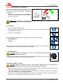
8.1_SWITCHING ON
After you have set up the machine as described in the chapter “7_Instructions for use”, switch on the “F_bus”
control system in order to start work.
Before starting work you can use the terminal to review and/or change the program values with
which your machine has been set up:
If the round baler is provided with a cutter system (mod.LTC), you can activate or deactivate the product
cutting knives:
• then check the position of the knives to see if they are engaged (knives in the chamber) or disengaged.
Before starting work check that the arms of the twine binder or net wrapper are in the rest position and that the
respective cutting devices are unloaded.
Take a position on the swathe; open the pick-up stop valve ("OPEN" position) and lower it.
Check that the tailgate is closed correctly:
• the manometer should indicate about 30bar,
You can now engage the PTO and begin collection.
The rotation speed of the PTO must be between 450÷540 rpm, and must not exceed this range of values.
For further information on how to change the programming of the “F_bus” control system and how to engage
and disengage the knives, see chapters:
• “10-QT_QuickTronic”.
• “10-ET_EasyTronic”.
8.2_FEED SPEED
The feed speed depends on the type of product to be baled and the ground contours.
8.3_LOADING (optional kit)
If your round baler is provided with the loading indicator kit, and the function has been activated, you can
monitor the product loading inside the chamber.
For further information on how to load with the loading indicator kit, see paragraph:
• QuickTronic = “10-QT.4_Work phase”.
• EasyTronic = “10-ET.4_Work phase”.
8.4_FORMATION OF THE BALE
Using the terminal of the “F_bus” system, you can follow all the various phases in the formation of the bale.
For example:
• Bale diameter.
• Type of binding (or wrapping) active (TWINE or NET).
• Binding method (AUTOMATICALLY MODE or OPERATOR MODE).
If your machine is provided with a cutter system (mod.LTC):
• state of the knives (ON or OFF).
When you have reached the bale diameter value set and depending on the terminal type in use, the “F_bus”
system will warn you that you must stop the tractor immediately in order to allow the bale binder to bind the
bale.
For further information on the various phases of bale formation, see chapter “10_ F_bus control system”.
Chapter 8 – p.1
Round baler EXTREME
LT
8.5_BINDING
The “F_bus” control system can start and carry out the binding process at the end of each bale formation
AUTOMATICALLY MODE or in OPERATOR MODE.
For further information on the various binding phases, see paragraph:
• QuickTronic = “10-QT.4_Work phase”.
• EasyTronic = “10-ET.4_Work phase”.
8.6_BALE EJECTION
After binding, depending on the terminal type in use, the “F_bus” system will tell you on the terminal to open
the tailgate in order to eject the bale on the ground.
WARNING! Before opening the tailgate:
• Make sure that you are on flat ground or in a suitable position if the ground is sloping.
• Keep any persons away from the machine and especially from behind the tailgate.
Operate the lever of the hydraulic switch located on the tractor to open the tailgate.
Wait for the bale to be ejected then re-close the tailgate.
At this point the “F_bus” system, depending on the terminal type in use, will tell you that your machine is ready
to start a new work cycle.
If the tailgate should not re-close normally, the “F_bus” system, depending on the terminal type in use, will
warn you of the problem.
IMPORTANT! Never begin collection with the tailgate open or even just one hook open.
If your round baler is provided with an electronically controlled bale ejector device and this function has been
activated, the “F_bus” system will allow you to monitor directly on the display all the steps of:
• ejecting the bale,
• possible blockage of the bale.
Note: the “F_bus” control system may work with different types of terminal.
All the information regarding the various operations described above will therefore be different and
displayed depending on the terminal type in use.
All the more detailed information regarding the specific use of each terminal is given in chapter
“10_“F_bus” control system.
Chapter 8 – p.2
Round baler EXTREME
LT
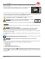
8.7_UNBLOCKAGE OF THE PRODUCT
WARNING! If the round baler should block up with product while working, do not try to remove
the product from the machine while it is in operation.
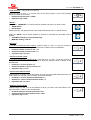
8.7.1_CLEARING THE PICK-UP (mod.LT)
The product is blocked between the rake and the tines of the pick-up.
WARNING! Before attempting to clear away the product
• Switch off the tractor, remove the keys from the dashboard and wait for all
the moving parts to stop completely.
• Switch off the “F_bus” system.
•
•
Shift and rotate the bracket "S" (on both the left and right sides) so as to free
the rake and then remove it.
Put on the cut resistant gloves and with the help of suitable equipment clear
the area where the product has blocked up.
CAUTION! Take care when releasing the brackets "S", the product
between the pick-up and the rake could cause the rake to spring up.
S
•
When you have completely cleared the area of the blockage remount the rake and secure it again with the
brackets “S”.
• After completing the operations described above re-engage the PTO.
If the pick-up fails to turn the transmission safety bolt of the pick-up could have sheared.
To replace it consult the paragraph “9.2.1_Replacement of the pick-up safety device”.
8.7.2_CLEARING THE PICK-UP CUT (mod.LTR and LTC))
The product is jammed between the collection channel plate and the tines of the pick-up.
WARNING! Before attempting to clear away the product:
• Stop and switch off the tractor, remove the keys from the dashboard and
wait for all the moving parts to stop completely.
• Switch off the “F_bus” system.
•
•
•
Release and remove the safety pin "S" (on both
left and right sides), and raise the securing hook
"G".
Remove the collection channel plate.
Put on protective gloves and clear the area of
the
blocked
product
using
appropriate
equipment.
G
S
•
When you have cleared the blockage completely, replace the collection channel plate and secure it again
with the hook "G" and the pin “S”.
• After completing the operations described above re-engage the PTO.
If the pick-up fails to turn, the bolt of the transmission safety system could have sheared. To replace it consult
the paragraph “9.2.1_Replacement of the pick-up safety device”.
Chapter 8 – p.3
Round baler EXTREME
LT
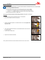
8.7.3_CLEARING THE ROTOR (mod.LTR and LTC)
An excessive volume of the product is blocked between the rotor and the collection channel.
Manual clearing of the cutter assembly:
WARNING! Before attempting to clear away the product:
• Stop and switch off the tractor, remove the keys from the dashboard and
wait for all the moving parts to stop completely.
• Switch off the “F_bus” system.
A) Raise the right guard and pull out the crank handle for unblocking from its seat.
B) Move the rotor engagement lever "L" to the neutral position and insert the crank handle on the shaft of the
distribution box.
C) Using the handle rotate the rotor anticlockwise for about 1/2÷3/4 of a turn to free it from the product
accumulated.
(B)
(A)
(C)
L
If it should be necessary to remove a foreign body manually (stone, stick, etc.) before doing this remember to
put on the cut resistant gloves and use appropriate equipment.
CAUTION! If your machine is equipped with a cutting system (mod.LTC), take great care in
performing these operations as the area of the rotor is very dangerous due to the presence of
cutting knives.
If necessary to remove the collection channel plate, consult the paragraph “8.7.2_Clearing the pick-up”.
•
•
•
•
When you have cleared the area concerned completely remove the crank
handle and put it back in its housing; close the guard.
Move the engage lever "L" back to the run position.
Replace the collection channel plate if it was removed previously.
After completing the operations described above re-engage the PTO.
L
If the rotor should fail to rotate:
• Ensure that you have moved the engage lever "L" correctly.
• The bolt of the mechanical transmission safety system could have sheared.
To replace it consult the paragraph “9.2.2_Replacing the rotor’s mechanical safety device”.
Automatic clearing "AFC" of the rotor:
If your round baler is provided with "AFC" safety devices, reduce the number of rpm of the tractor to a
minimum and wait for the product to be cleared.
This device is engaged and disengaged automatically until the blockage has been cleared.
If the tractor engine should stall, start it up again and keep it at a minimum.
If your machine is equipped with a cutting system (mod.LTC):
• If you are working with the knives inserted, it is a good idea to stop the machine and disengage the knives
before clearing the product “7.6.6_Cutter system”, then proceed as described.
• Engage the knives again on completion of this operation.
WARNING! During this entire operation do not approach or allow anyone else to approach the
machine. The "AFC" device could clear the blockage at any moment and the rotor could
resume its normal rotation.
Chapter 8 – p.4
Round baler EXTREME
LT
8.8_STOPPING THE MACHINE
IMPORTANT! On finishing work the operator must:
• Stop the machine.
• Make sure that all the moving parts of the machine have stopped and are in
the rest position.
• Stop the tractor motor and remove the keys from the dashboard.
• Switch off the “F_bus” system.
8.9_PARKING
CAUTION! Before taking the machine back to its storage area make sure that there is no bale
still loaded.
At the end of work deposit the machine in a suitable flat area to avoid sudden accidental movements.
• Place the parking chocks under the wheels.
• Lower the parking jack to the ground and block it with the safety pin. Raise the machine by 2÷3cm from its
connection to the tractor in order to unhook it.
•
•
Raise the cardan shaft support, then disconnect
the cardan shaft from the tractor and rest it on
the support.
Secure it with the chain.
De-pressurise hydraulic circuit and:
•
•
•
•
•
•
Rest the small wheels of the pick-up on the
ground; move the lever of the stop valve to the
"CLOSED" position; then disconnect the tube
and place it in its special housing “A”.
Disconnect all the other tubes of the hydraulic
system and place them in their special housing
“B”.
B
A
Disconnect the electrical feed lines, from the lighting system and wrap them
around the support.
Disconnect the signal cable of the “F_bus” system and wrap it around the
tube support.
Then remove the control terminal and put it in a place protected from dust
and adverse weather conditions.
Remove the safety pin and the locking pin from the towing eye of the
steering bar and then unhook the tractor from the machine.
Remove the tractor from the vicinity of the baler.
Chapter 8 – p.5
Round baler EXTREME
Chapter 8 – p.6
LT
Round baler EXTREME
LT
9_MAINTENANCE AND ADJUSTMENT
9.1_ROUTINE MAINTENANCE
IMPORTANT! Regular careful maintenance lengthens the life of your machine and guarantees
your personal safety.
All the screwed/bolted assemblies must be tightened according to the values contained in the table
“11.4_Torque wrench settings”, unless stated otherwise.
FOR THIS MACHINE THE VALUE "8.8" REPRESENTS THE STANDARD AND THE MINIMUM
QUALITY USED.
Diameter and torque wrench settings for the quality of the materials according to DIN ISO 898.
The lubrication of any machine with rotating and rubbing parts is of great importance for the duration and
working order of the machine. Lubrication should therefore be done regularly and systematically “11.4_Torque
wrench settings”, unless stated otherwise.
WARNING! Before doing any maintenance on the machine:
• Keep in mind all the basic safety rules contained in the chapter “4_General safety
regulations”.
Do maintenance work only with the machine off and all the moving parts
completely still:
• Always turn off the tractor and remove the keys from the dashboard.
• Always switch off the “F_bus” system.
• Never raise the machine from the ground.
Prearrange maintenance work for which the due dates are known.
This manual is of a purely informative nature. The periods between maintenance operations are for normal
working conditions of the round baler therefore if the round baler is used in more sever conditions it is logical
to increase the frequency of maintenance.
Replace any damaged parts:
ALWAYS USE ORIGINAL SPARE PARTS.
WARNING!: If it is necessary to do maintenance with the tailgate open, or inside the bale
formation chamber itself, lock the tailgate in position using the tailgate safety lock following
the instructions shown in paragraph “4.5.12_Tailgate safety lock device”.
Do the maintenance work exactly as indicated in this manual and have any worn or
damaged parts replaced by specialised personnel.
Chapter 9 – p.1
Round baler EXTREME
LT
9.2_MAINTENANCE AND ADJUSTMENT OF SAFETY DEVICES
Some of the safety devices listed in chapter “4.5_Safety devices” of this manual need to be reset and/or
adjusted after they have come into action.
9.2.1_REPLACEMENT OF THE PICK-UP SAFETY DEVICE
If the safety device bolt located in the safety device of the pick-up should break, replace it with one of identical
quality:
• Bolt “B” TE M8X 45-10.9 UNI 5738 - DIN 960 (not galvanised; partially threaded).
•
•
•
Loosen the screws "V" and pull out the safety guard located on the left side of the pick-up.
Remove the bolt and make sure that there are no pieces of the sheared bolt caught between parts of the
transmission.
Realign the safety device holes, manually rotating the screw feeder; reinsert the new bolt and tighten it.
mod.LT
•
mod.LTR and LTC
B
Remount the safety guard and replace the screws “V”.
9.2.2_REPLACING THE ROTOR’S MECHANICAL SAFETY DEVICE (mod.LTR and LTC)
If the bolt located on the mechanical safety device of the rotor should break replace it with one of identical quality:
• Bolt “B” TE M14X 60-8.8 UNI 5738 - DIN 960 (not galvanised; partially threaded).
•
•
•
•
Loosen the screws "V" and remove the safety
guard located on the left side of the rotor
transmission.
Remove the bolt and make sure that there are
no pieces of the sheared bolt caught between
parts of the transmission.
•
B
Shift the rotor to neutral (lever "L" to engage the rotor into the neutral position).
Using the crank handle "M" (provided) realign the safety device holes; insert the new bolt and tighten it.
L
•
V
M
L
Re-engage the rotor (lever "L" to engage the rotor into the engaged position), remove the handle "M" and
replace it in its housing.
Remount the guard and replace the screws “V”.
WARNING! Before engaging the PTO make sure that you have removed the handle "M" and
repositioned it in its housing.
Chapter 9 – p.2
Round baler EXTREME
LT
9.3_CHAIN TENSION ADJUSTMENT
Regularly check the tension of the transmission chains and the working of the
automatic stretchers where provided.
• The value "F" of chain stretching must be 5÷10mm.
F
9.3.1_ADJUSTMENT OF THE AUTOMATIC STRETCHERS
The roller chains of the machine are stretched automatically by spring stretchers; regularly check the correct
tension of the chains and readjust the tension whenever necessary.
Check the working of the automatic stretchers.
To check and adjust the tension of the chains raise the left lateral guard:
• Loosen the nut "d1" and, turning the nut "d2", adjust the distance "X", which should be 10÷15mm.
• Once this setting has been made tighten again the nut "d1".
d1
X
d2
d1
d2
•
Lower and close the lateral protection guard again.
9.3.2_ADJUSTMENT OF THE MANUAL STRETCHERS
Some of the roller chains of the machine are stretched by stretchers whose adjustment must be done
manually. Regularly check the correct tension in the chains and adjust it whenever necessary.
Check the manual adjustment of the stretchers.
To check and adjust the tensioning of the chains, open the left side cover (close the cover once the
adjustment(s) made is complete).
Large roller chain tension adjustment (mod.LT):
•
•
•
•
•
Loosen the screws "V1" and remove the guard.
Loosen the screws "V2" and the lock nut "d".
Screw in or out the adjusting screw "VR" so as
to obtain the correct tension in the chain.
Once the correct tension is obtained, tighten the
lock nut "d" again and then the screws "V2".
Replace the guard and screw it in place with the
screws “V1”.
V2
V1
d
VR
Chapter 9 – p.3
Round baler EXTREME
LT
Large roller chain tension adjustment (mod.LTR and LTC):
•
•
•
•
Loosen the screws "V1" and remove the guard.
Loosen the 3 screws "V2" and using a hammer,
adjust the tension of the chain by shifting the
stretcher upwards with light hammer strokes.
Once the correct tension is obtained screw back
the 3 screws "V2".
Replace the guard and screw it in place with the
screws “V”.
V2
V1
Collection assembly transmission chain tension adjustment (mod.LT):
•
•
•
•
•
Loosen the screws "V1" and remove the
protection guard.
Loosen the screws "V2" and the lock nut "d".
Screw or unscrew the adjustment screws "VR"
in order to obtain the correct tension of the chain.
Once the adjustment has been made, tighten the
lock nut "d" again and then the screws "V2".
Replace the protection guard and secure in
place by tightening the screws “V1”.
V1
V2
d
VR
Collection assembly transmission chain tension adjustment (mod.LTR and LTC):
•
•
•
•
Loosen the screws "V1" and remove the guard.
Loosen the 3 screws "V2" and using a hammer,
adjust the tension of the chain by shifting the
stretcher downwards with light hammer strokes.
Once the correct tension is obtained screw back
the 3 screws "V2".
Replace the guard and screw it in place with the
screws “V1”.
V1
V2
Rotor chain tension adjustment (mod.LTR and LTC):
To check and adjust the tension of the rotor chain raise the right lateral gull-wing protection guard:
•
•
•
Loosen the screws "V1" and remove the guard.
From inside the side of the machine, loosen the
2 screws "V2".
Loosen the lock nut "d" and, screw in or out the
adjusting screw "VR" so as to obtain the correct
tension in the chain.
VR
V1
d
V2
•
•
•
Once the correct tension is obtained screw back the lock nut "d" and from the inside of the side of the
machine screw back the 2 screws "V2".
Replace the guard and screw it in place with the screws "V1".
Lower and close the right lateral gull-wing protection guard “V1”.
Chapter 9 – p.4
Round baler EXTREME
LT
Pick-up chain tension adjustment (left side):
•
•
•
•
Unscrew and remove the screws "V1" and the
lateral guard of the pick-up.
Loosen the 2 screws "V2" and using a hammer,
adjust the tension of the chain by shifting the
stretcher upwards with light hammer strokes.
Once the correct tension is obtained screw back
the 2 screws "V2".
Replace the guard and screw it in place with the
screws “V1”.
V1
V2
Pick-up chain tension adjustment (right sides):
•
•
•
•
Unscrew and remove the screws "V1" and the
left lateral guard of the pick-up.
Loosen the 2 screws "V2" and using a hammer,
adjust the tension of the chain by shifting the
stretcher with light hammer strokes
Once the correct tension is obtained screw back
the 2 screws "V2".
Replace the guard and screw it in place with the
screws “V1”.
V1
V2
Chapter 9 – p.5
Round baler EXTREME
LT
9.4_ADJUSTMENT OF THE SCRAPERS
IMPORTANT! Both areas of the scrapers present on the round
baler must always be kept adjusted correctly and clean.
The scrapers on the round baler are:
1) engine roller scraper,
2) lower roller scraper.
1
2
WARNING! Before doing any kind of maintenance work and/or adjustments to
the scrapers:
• Stop the machine and wait for all the moving parts to stop.
• Turn off the tractor engine and remove the keys from the dashboard.
IMPORTANT! When you adjust the distance “D” between the blade and the roller, the scraper
blade must never touch the roller.
Chapter 9 – p.6
Round baler EXTREME
LT
9.4.1_LOWER ROLLER SCRAPER
•
Open the tailgate so that you can proceed with the work and lock it in place by moving the lever located on
the valve block to the stop position (lock closed) “4.5.12_Tailgate safety lock device”.
•
Loosen the 4 screws "V" (2 on each side) and
using a hammer adjust (by lightly hammering the
scraper) the distance "D" between the roller and
the scraper blade:
Distance "D" = 0÷0.5mm.
Once the correct distance has been obtained
screw back the 4 screws "V" and check again
that the distance "D" has not changed as a
result of tightening the screws.
•
•
•
•
V
D
V2
Make sure that there are no persons near the machine (if there are they must be kept away) and start the
tractor again.
Unlock the tailgate safety lock by moving the lever back to its original position and re-close the tailgate.
IMPORTANT! The manufacturer always mounts the door’s roller and the scraper using the hole
and the slots indicated by position “A” in the diagram.
position “A”
position “B”
Ru
Ra
If the round baler is to be used upon rocky terrain, we recommend using the following procedure to moving the door’s
roller and the relative scraper to position “B”, as shown in the diagram.
•
•
•
Open the door and use the lever on the valve block to lock it in place (lock closed) “4.5.12_door blocking
safety device”.
In order to move the scraper “Sc” to position “B”, loosen and remove its fastening screws.
Fasten the scraper in its new position using the same screws, without tightening them completely.
ATTENTION! Use extreme caution when manoeuvring the scraper:
• The scraper’s blade is extremely sharp
• The scraper’s weight represents a crushing hazard
•
•
Next, loosen and remove the screws which fasten the roller “Ro” in order to move it to position “B”.
Fasten the roller in its new position using the same screws.
ATTENTION! Use extreme caution when manoeuvring the door’s lower roller: its weight
represents a crushing hazard.
•
•
•
•
Next, set the proper distance “D” between the scraper’s blade and the roller itself, as described in section
“9.4.2_Lower roller scraper”.
Once this adjustment has be performed, tighten the screws which fasten the scraper “Sc” completely and
double check the distance “D” to make sure that it has not be altered by the tightening of the screws.
If anyone else is present, make sure that they stay at a safe distance from the machine.
Turn the tractor back on, release the door blocking safety device by moving the lever back to its original
position and close the door.
Chapter 9 – p.7
Round baler EXTREME
LT
9.5_BELTS
9.5.1_BELT ADJUSTMENTS
Check the movement of the belts while they are working:
• The machine must be set up for a hard bale core, standing on flat ground and with the tailgate closed well
with the side hooks.
• Engage the power take-off at low speed and watch the movement of the belts in relation to the guides
from a position behind the machine.
If the belts shift towards the right, make the adjustment to position "R1" (on the right side), as follows:
1) Open the tailgate slightly in order to:
• loosen the belts
• then move the adjustment point "R1" to a position that allows adjustment to be done more easily.
Lock the tailgate in the open position by moving the lever located on the valve block to the locked position
(lock closed) “4.5.12_Tailgate safety lock device”.
•
•
Stop the machine and wait for all the moving parts to stop.
Turn off the tractor engine and remove the keys from the dashboard.
2) Loosen the screw "A" (right side) and screw in or out the lock nuts "d" of the stretcher so as to lower the
extreme right of the roller; then screw back the screw "A" and the lock nuts "d".
3) Make sure that there are no persons near the machine (if there are keep them away) and start the tractor
again; unlock the tailgate safety lock by moving the lever to its original position and close the tailgate
again.
4) Start the tractor and engage the power take-off at idle speed to check the movement of the belts again.
If necessary. repeat the adjustment at points 1, 2, 3 and 4 until the right adjustment has been made.
If the belts tend to shift towards the left carry out the same operations on the left side.
R2
d
R1
R1
A
If the belts should also shift at the front you will have to repeat the adjustment at point “R2”:
a) Open the tailgate slightly to loosen the belts; lock the tailgate by moving the lever located on the valve
block to the locked position (lock closed) “4.5.12_Tailgate safety lock device”.
•
•
Stop the machine and wait for all the moving parts to stop.
Turn off the tractor engine and remove the keys from the dashboard.
b) Raise the gull-wing protection guard on the side of the machine on which you intend to make the
adjustment.
c) Find a position from which you can reach the adjustment point "R2" located under the top cover of the
machine and loosen the screw "A".
d) Loosen or tighten the lock nuts "d" of the stretcher so as to lower or raise the end of the roller; then screw
back the screw "A" and the lock nuts "d". Then close the gull-wing protection guard again.
e) Make sure that there are no persons near the machine (if there are keep them away) and start the tractor
again; unlock the tailgate safety lock by moving the lever to its original position and close the tailgate
again.
f) Start the tractor and engage the power take-off at idle speed to check the movement of the belts again.
If necessary repeat the adjustment at points a, b, c, d, e, f, until the right adjustment has been made.
If you are unable to obtain a satisfactory result consult our Assistance Service.
Chapter 9 – p.8
Round baler EXTREME
LT
9.5.2_BELT MAINTENANCE (REPLACING AND RECONDITIONING)
To replace or recondition the belts proceed as follows:
•
fully open the tailgate;
•
insert the safety pin “S” in the hole;
•
when the tailgate is lowered the rocker arm rests on the “S” pin
and the belts slacken.
IMPORTANT!:
• do not hydraulically insist in closing the tailgate once
the rocker arm is rested on the “S” pin,
• do not lower the tailgate too much so as not to risk not
being able to enter the machine.
S
Block the tailgate with the safety device to prevent the tailgate accidentally closing “4.5.12_ Tailgate stop
safety device”.
Now, and only now, carry out belt replacement and reconditioning.
After completing belt replacement and reconditioning:
release the tailgate safety device and reopen it completely;
remove the “S” pin and return it to its housing;
•
close the tailgate again.
IMPORTANT!
The “S” pin must only ever be used for the operation described above. Any other use could
cause serious damage to the machine.
IMPORTANT! La variazione massima consentita tra la cinghia più lunga e quella più corta deve
essere tra 2,5÷3cm
It is possible to add one or more sections to the belt
provided that they are of the same type.
“D” min.
Note: Between the two clinches, you must leave a minimum distance "D" of 50cm; you must also
adhere to the direction of movement indicated by the arrows.
Chapter 9 – p.9
Round baler EXTREME
LT
9.5.3_CLINCHING OF THE BELTS WITH A "PROFI 5" CLINCHING MACHINE
(1)
(2)
(3)
(4)
(5)
(6)
(7)
(8)
(9)
(10)
(11)
(12)
(13)
(14)
(15)
(16)
(17)
(18)
(19)
(20)
1) Cut the ends of the belt at perfect right angles.
2) Position the "PROFI 5" clinching machine in the vice with the holes forward. Open the vice to the
maximum.
3) Insert the rivets from the packet of clinches (fasteners) in the holes starting from the left side.
4) Two rivets of each clinch must be positioned in each hole.
5) Close the vice until the clinch touches the stopper leaving enough space to insert the belt.
6) Insert the belt in line with the marking (depending on the width of the belt and the number of clinches).
7) Hold the belt in position and strongly squeeze the rivets by closing the vice.
8) The belt must touch the rivets, closing the vice until it touches the surface of the belt.
9) Introduce the punch as far as the stopper in the left hole. To obtain a perfect riveted joint hit the punch
three more times with a hammer.
10) The rest of the riveting must be done from right to left. WARNING! The weight of the hammer must be
500÷800g.
11) Open the vice and remove the belt folding it slightly backwards.
12) Insert the successive clinches and position the belt on the first pin on the left to ensure the correct pitch
and continue clinching in the same way.
13) Hammer all the rivets on a flat base making sure not to crush the eyelets.
14) The desired width of the clinch pack can easily be obtained by simply twisting until it breaks.
15) Cut the protruding linking thread.
16) The method of clinching is the same for all belt widths.
17) Repeat the entire process on the other end of the belt remembering to clinch on the same side.
18) Make a diagonal cut of about 2cm leaving a border of 5mm from the clinches on both sides.
19) Connect the two ends of the belt and insert the little bar in the eyelets to ensure an exact joint.
20) When the two ends have been connected the external edges of the belt should be in line.
The arrow (figure 20) indicates the direction of movement of the belt in the machine
IMPORTANT! Take great care in mounting the belts on the machine; they must follow the
direction of rotation as shown in the figure “11.6_Belt paths”.
Chapter 9 – p.10
Round baler EXTREME
LT
9.5.4_CLINCHING OF THE BELTS WITH A "PROFI 19" CLINCHING MACHINE
(1)
(2)
(3)
(4)
(5)
(6)
(7)
(8)
(9)
(10)
(11)
(12)
(13)
(14)
(15)
(16)
(17)
(18)
(19)
(20)
1) Cut the ends of the belt at perfect right angles.
2) Position the "PROFI 19" clinching machine in the vice with the holes forward. Open the vice to the
maximum.
3) Insert the rivets from the packet of clinches (fasteners) in the holes starting from the left side.
4) Two rivets of each clinch must be positioned in each hole.
5) Close the vice until the clinch touches the stopper leaving enough space to insert the belt.
6) Insert the belt in line with the marking (depending on the width of the belt and the number of clinches).
7) Hold the belt in position and strongly squeeze the rivets by closing the vice. Pay attention to the markings
for the different lengths.
8) The belt must touch the rivets, closing the vice until it touches the surface of the belt.
9) Introduce the punch as far as the stop in the left hole. To obtain a perfect riveted joint hit the punch three
more times with a hammer.
10) The rest of the riveting must be done from right to left. Warning! The weight of the hammer must be
500÷800g.
11) Instead of a hammer it is easier and faster to use a special compressed air pistol (compressed air at max.
6bar).
12) Open the vice and remove the belt folding it slightly backwards.
13) Hammer all the rivets on a flat base making sure not to crush the eyelets.
14) The desired width of the clinch pack can easily be obtained by simply twisting until it breaks.
15) Cut the protruding linking thread.
16) The method of clinching is the same for all belt widths.
17) Repeat the entire process on the other end of the belt remembering to clinch on the same side.
18) Make a diagonal cut of about 2 cm leaving a border of 5mm from the clinches on both sides.
19) Connect the two ends of the belt and insert the little bar in the eyelets to ensure an exact joint.
20) When the two ends have been connected the external edges of the belt should be in line.
The arrow (figure 20) indicates the direction of movement of the belt in the machine
IMPORTANT! Take great care in mounting the belts on the machine; they must follow the
direction of rotation as shown in the figure “11.6_Belt paths”.
Chapter 9 – p.11
Round baler EXTREME
LT
9.6_ADJUSTMENT OF THE BINDERS
9.6.1_DOUBLE TWINE BINDER
The “F_bus” control system allows you to control the parameters with which to
set the double twine tying, independently of the value of the bale diameter:
“A” = distance of the twine from the head of the bale.
“B” = number of turns of twine around the head.
“C” = number of turns of twine around the centre.
To modify the values consult the paragraph:
• QuickTronic = “10-QT.3.1_Programming”.
• EasyTronic = “10-ET.5.1_Program Menu”.
C
B
B
A
WARNING! Before doing any maintenance or making any adjustments to the
double twine binder:
• Stop the tractor, remove the keys from the dashboard and wait for all the
moving parts of the machine to stop completely.
• Switch off the control system.
Twine braking device adjustment:
There are some twine braking devices on the round
baler:
• “F1” located on the twine spool box,
• “F2” located on the arm of the binder,
to adjust the tension of the twine.
( F2 )
( F1 )
Adjust the tension of the twine on the bale by turning the nuts "d" and screws
"V" of the twine braking device, to compress or release the springs "M":
• Tightening the spring "M", the twine will be more taught.
• Loosening the spring "M", the twine will be slacker.
V
CAUTION! Take great care when working near the twine braking
devices located on the arm of the binder, and the blade of the
binder.
M
d
Twine cutter blade extension:
If it is necessary to tie a great deal inside the edge of
the bale (twine cutter side) it may be necessary to
adjust the blade arm by extending the small blade:
• loosen the four nuts "d" and slide the two parts
to the right position.
• then tighten again the four nuts "d".
+
d
Replacing the blade:
If the blade of the double twine binder does not cut the twine any more, you can:
• replace it (if broken)
• turn it round (if worn).
Unscrew the 2 screws "V" and replace it with one that is the same or turn it
round; screw it back in place with the 2 screws “V”.
CAUTION! Take great care around the blade of the binder.
Chapter 9 – p.12
V
Round baler EXTREME
LT
9.6.2_NET WRAPPER
The “F_bus” control system gives you the possibility of setting the number of turns for wrapping the bale.
To change this value consult paragraph:
• QuickTronic = “10-QT.3.1_Programming”.
• EasyTronic = “10-ET.5.1_Program menu”.
WARNING! Before doing any maintenance or making any adjustments on the
net wrapper:
• Stop the tractor, remove the keys from the dashboard and wait for all the
moving parts of the machine to stop completely.
• Switch off the control system.
Adjustment of the net arm movement:
•
•
Raise the right gull-wing protection guard.
Loosen the nut "d" and screw or unscrew the adjustment screw "VR", in
order to obtain the right distance of the net arm from the intermediate
roller.
Note: if you tighten the screw "VR" too much, the arm could move
forward and crash against the roller during binding. If instead, you
loosen the screw "VR" too much, the movement or the arm could be
insufficient and then the net would not be picked up and the bale not
tied.
•
VR
d
When the right adjustment is obtained, tighten the nut "d" and re-close
the protection guard.
CAUTION! Take great care when working near the arm of the wrapper and especially the
blades.
Replacing the blade:
If the wrapper blade sections do not cut the net (the blades are worn or
broken) they must be replaced:
• Remove the rivets that originally fixed the blades.
• Replace the worn or broken blades and secure them again to the wrapper
arm using M6X 20 screws (instead of rivets).
CAUTION! Take great care regarding the blade sections.
Chapter 9 – p.13
Round baler EXTREME
LT
9.7_ELECTRICAL AND ELECTRONIC COMPONENTS
•
•
Check that the cables of the electrical system and the control unit have not been crushed or damaged.
Check that all the sockets, plugs, cables and sensors are always cleaned of any deposits of earth or the
product.
• Check and if necessary replace broken bulbs in the lighting system.
Further information regarding the maintenance of the control unit can be found in the chapter “10_F_bus
control system”.
IMPORTANT! After the first 200 bales produced check the machine in regard to the points
described above.
9.7.1_SENSORS
A series of “proximity switches” (sensors) have been placed on the round
baler. These regulate and monitor the various working phases of the machine
through the “F_bus” system.
Adjust the distance "X" between the sensor "S" and its abutment "R", as
shown in the figure (the example is only indicative):
• “X” = 1÷3mm
•
•
•
R
X
S
LED
With the “F_bus” control system switched on, turn the nuts that fix the sensor to its support in order to
move it closer to or further from its abutment.
When the "LED" light located on the sensor comes on this means that you have obtained the right
distance "X".
Then secure the nuts and check that the "LED" of the sensor still comes on as the sensor may have been
moved again when the nuts were tightened.
IMPORTANT! Adjust the sensors so that they never touch or collide with their abutments when
working.
CAUTION! Make all the adjustments on all the sensors located on the machine observing the
safety regulations and taking great care at the points where there could be particular danger.
If it should be necessary, in order to gain access to the sensors, to open or remove the guards, remember
always to close them and reposition them after finishing the adjustments.
Chapter 9 – p.14
Round baler EXTREME
LT
9.8_ADJUSTMENT OF THE PICK-UP
9.8.1_ADJUSTMENT OF THE WORKING HEIGHT OF THE PICK-UP
The working height of the pick-up is adjusted by moving the small wheels to one of the predetermined
positions in the same way on each side of the pick-up.
IMPORTANT! The pick-up tines must never touch the ground; therefore adjust the working
height of the pick-up so that the pick-up tines remain above the ground by a minimum of
2÷3cm.
For further information consult the paragraph “7.6.3_ Adjustment of the pick-up wheels”.
9.8.2_HYDRAULIC RAISING OF THE PICK-UP
You can raise and lower the pick-up easily using two lateral hydraulic jacks, by
moving the lever of the hydraulic distributor on the tractor, first opening the
stop valve (valve lever in the "OPEN" position).
OPEN
For further information consult the paragraph “7.4.3_ Connection of the hydraulic system”.
9.8.3_REPLACEMENT OF THE PICK-UP TINES
WARNING! If the pick-up tines mounted on the roll-holder of the pick-up have
to be replaced:
• Stop the tractor, remove the keys from the dashboard and wait for all the
moving parts of the machine to stop completely.
• Switch off the control system.
Loosen the 4 screws "V" (2 above and 2 below) which fix the band
"F" corresponding to the tine to be replaced and then pull out the
band, passing the head of the screws "V" through the hole of the slot
located on the band.
V
F
V
Unscrew the bolt "B", remove the tine "D" and the related block "T".
Replace the pick-up tine "D" with a new one of the same type. Screw
back the block "T" and the bolt “B”.
B
D
T
Replace the band "F" inserting it over the screws "V" and then push
it all the way against the screw.
Finally screw back the 4 screws "V" with a tightening value of
15Nm
V
F
V
Chapter 9 – p.15
Round baler EXTREME
LT
9.8.4_ADJUSTMENT OF THE PICK-UP CAM
Adjust the position where the product is released from the pick-up tine by moving the cam located on the right
side of the pick-up.
WARNING!
• Stop the tractor, remove the keys from the dashboard and wait for all the
moving parts of the machine to stop completely.
• Switch off the control system.
•
Unscrew and remove the screws "V1" and the right guard of the pick-up.
V1
•
Loosen the 4 screws "V2" that hold the cam.
V2
Adjust the position of the cam, rotating it so as to
move the pick-up tine nearer or further from the
transport assembly (feeder if mod.LT; or rotary
feeder if mod.LTR, or cutter assembly if mod.LTC).
A
Rotate the cam towards the position:
“A” = to move the tine nearer to the pick-up
assembly.
“B” = to move the cam away from the pick-up
assembly.
•
•
Screw back the 4 screws "V2" to secure the cam again.
Replace the right guard and secure it with the screws “V1”.
Chapter 9 – p.16
B
A
B
Round baler EXTREME
LT
9.9_MAINTENANCE AND ADJUSTMENT OF THE CUTTER (mod.LTC)
The knives or false knives must be removed or put back whenever you do the following:
• Remove all or only some of the knives.
• Remove some of the knives for sharpening.
• Replace all or only some of the knives with false knives.
WARNING! Before removing or assembling knives:
• Open the tailgate and lock it in position using the Tailgate safety lock device, following the
instructions given in the paragraph “4.5.12_Tailgate safety lock device”.
• Before closing the tailgate remember to release its safety lock.
•
•
Stop the tractor, remove the keys from the dashboard and wait for all the
moving parts of the machine to stop completely.
Switch off the control system.
•
The knives are sharp and cut easily, it is advisable to use cut resistant gloves!
9.9.1_REMOVAL OF THE KNIVES
To remove the knives they must be disengaged, doing this directly from the terminal of the “F_bus” system.
In this regard consult paragraph:
• QuickTronic = “10-QT.3.4_Cutter device”.
• EasyTronic = “10-ET.6.3_Cutter device”.
a) Move the rotor engagement lever "L" to the
neutral position.
b) Release the knives by moving the handle,
located on the right side of the machine, to
position "2" (lever lowered).
(a)
(b)
L
2
•
Enter the bale formation chamber and take hold of the knives to be removed at the tip then lift and pull
them out.
To extract them more easily you can rotate the rotor manually proceeding with caution.
IMPORTANT! It is necessary to put false knives in the place of the knives removed so that the
product does block up the seats of the knives and make it difficult to replace the knives later.
a) When you have finished this operation, anchor
the knives again moving the handle to position
"1" (lever raised).
b) Shift the engagement lever "L" back to the drive
position.
(a)
1
(b)
L
Chapter 9 – p.17
Round baler EXTREME
LT
9.9.2_ASSEMBLY OF THE KNIVES OR FALSE KNIVES
To mount the knives or the false knives, the knives must be disengaged doing this directly from the terminal
of the “F_bus” system.
In this regard consult paragraph:
• QuickTronic = “10-QT.3.4_Cutter device”.
• EasyTronic = “10-ET.6.3_Cutter device”.
a) Move the rotor engagement lever "L" to the
neutral position.
b) Release the knives by moving the handle,
located on the right side of the machine, to
position "2" (lever lowered).
(a)
(b)
L
2
•
•
Enter the bale formation chamber and insert the knives or false knives in the slots.
To make this easier you can rotate the rotor manually proceeding with caution.
Make sure that they are correctly inserted on the pin.
IMPORTANT! If the knives or false knives are not correctly anchored there is the danger that
they will enter the bale formation chamber together with the product to be baled.
a) When you have finished this operation anchor
the knives again by moving the handle to
position "1" (lever raised).
b) b) Move the engage lever "L" back to the run
position.
(a)
(b)
L
1
9.9.3_SHARPENING OF THE CUTTER KNIVES
The knives should be sharpened with suitable equipment whenever necessary.
Bear in mind that knives sharpened well reduce the power requirement and give a better quality cut.
IMPORTANT! When sharpening, be careful not to cause the knives to heat up as this can
compromise their resistance to wear.
•
Only one SIDE of the knife should
be sharpened.
SIDE
WARNING!
• Always work with care bearing in mind the safety regulations.
• The knives are sharp and cut easily; handle them with great care and always use adequate
gloves and/or protective gear.
Chapter 9 – p.18
Round baler EXTREME
LT
9.10_WHEELS AND TYRES
Tyres of various dimensions can be fitted on the round baler. Check the inflation pressure regularly for the type
of tyre fitted to you machine referring to the pressure values given in the table “11.5_Tyre pressure values”.
•
•
•
The inflation pressure of the pick-up wheels should be: 2,5bar.
Check the torque of the nuts on the stud bolts of the wheel hubs regularly. It should be
250Nm.
Repairs to the wheels and tyres must be done by specialised personnel provided with
suitable equipment.
9.11_BOLT TIGHTENING
Regularly check the securing bolts and screws and if necessary adjust them to the torque values advised in
the table “11.4_Torque wrench settings”.
• Check if all the bolts are correctly tightened after the first three hours of work.
• Check if all the screws and bolts are correctly tightened after the first 10 bales formed by the machine.
9.12_WELDING
WARNING! FIRE RISK!
• Never do welding work on your baler when there is a bale inside the
chamber.
Before doing welding work on your baler:
• Stop the tractor, remove the keys from the dashboard and wait for all the
moving parts of the machine to stop completely.
• Disconnect all the electrical and electronic functions
• Switch off the control system.
For further information consult the chapter “4.2_Safety warnings”.
In any case take great care in these operations.
9.13_LUBRICATION
Regular lubrication is the best guarantee against breakdowns and repairs. Apply lubricants regularly and
always use good quality greases and oils.
IMPORTANT!
• In general use grease type: AGIP GR MU EP0
• In the transmission box use oil type: AGIP BLASIA EP 150
• In the automatic oil system tank for the chains use oil type: AGIP OSO 100
•
Lubricate and grease all rotating parts: crown wheels, supports, bearings, chains, pins and shafts
WARNING! Always apply lubricants in respect of the safety regulations contained in the
chapter “4_General safety regulations”.
Before greasing or oiling you baler:
• Stop the tractor, remove the keys from the dashboard and wait for all the
moving parts of the machine to stop completely.
• Switch off the control system.
Note: if it should be necessary to open or remove any guards in order to access the various lubrication
points, always remember to close and reposition them afterwards.
Chapter 9 – p.19
Round baler EXTREME
LT
9.13.1_GREASING
Lubricate and grease all the points indicated by the special adhesive signs: “7500214”, present on the
machine every 30 hours of work.
4
6
8
9
1
12
2
15
5
3
14
7
10
•
•
11
13
Before injecting grease into the greasers it is necessary to clean carefully the greaser fittings to prevent
mud, dust or foreign bodies from mixing with the grease which would reduce or even annul the effect of
the lubrication.
Injecting a large quantity of grease under high pressure could damage the protection of the bearings;
therefore do this operation with due care.
List of the various lubrication points present on the baler:
(1)
(2)
1) Tailgate jack (right and left sides).
2) Pressure jack (right and left sides).
(3)
3) Automatic chain stretchers (left side).
4) Tailgate hinges (left and right sides).
5) Tailgate hooks (left and right sides).
Chapter 9 – p.20
(4)
(5)
Round baler EXTREME
(6)
6)
7)
8)
9)
(7)
(9)
( 12 )
( 13 )
Main belt stretcher arm (right and left sides).
Parking jack.
Net counter roller (right and left sides).
Net release (right side).
( 10 )
10)
11)
12)
13)
(8)
LT
( 11 )
Twine binder arm.
Pick-up transmission safety device (left side).
PTO shaft.
Feeder connector rod (left side - mod.LT).
( 14 )
14) Rotor support (left side - mod.LTR and LTC).
( 15 )
15) Cardan shaft: lubricate and grease according to the instructions contained in the user and maintenance
booklet provided together with the cardan shaft.
Chapter 9 – p.21
Round baler EXTREME
LT
9.14_HYDRAULIC OIL
The hydraulic controls are high precision components and require clean filtered oil:
• Regularly check the level and state of contamination.
• Check the seal and locking of the hydraulic tubes and for any oil leaks.
• Check and top up the oil in the transmission box and the automatic oil tank.
IMPORTANT! Use the oils advised by FERABOLI S.p.A. in chapter “9.13_Lubrication”; another
type of oil could create pumping problems.
9.14.1_AUTOMATIC OILING OF THE CHAINS
The round baler is provided with an automatic oiling system for the chains.
This system works every time the tailgate closes by means of the movement of a small pump.
The flow of oil can be regulated by adjusting the travel of the piston "P" located on the small pump.
If the flow of oil coming out is too low or too high, adjust the distance "D" so as to increase or decrease the
travel of the piston of the small pump:
•
•
Open the left lateral protection guard and move
to a position where you can reach the small
automatic oiling pump located directly under the
hinge of the guard.
Loosen the two hexagonal bolts "V" and slide
the pump along the slots in order to increase or
decrease the distance "D":
P
V
D
THE GREATER the distance "D" the greater is the flow of oil pumped and put into circulation by the
automatic lubrication system of the chains.
THE SMALLER the distance "D" the smaller is the flow of oil pumped and put into circulation by the
automatic lubrication system of the chains.
•
•
Screw back the two hexagonal bolts.
The maximum travel allowed is at least.
After making the adjustment, re-close the left lateral guard.
9.14.2_TANK
Check and top up the oil tank of the automatic oiling system of the chains:
• Open the left lateral protection guard.
• Unscrew the plug "T", fill up the oil tank and screw back the plug “T”.
The oil capacity of the tank is 1.5 litres.
• After filling the tank re-close the left lateral guard.
T
9.14.3_FILTER
Regularly check the condition of the filter of the automatic chain oiling system;
if you have to replace it:
• Open the left lateral protection guard.
• Loosen the clamps "F" and replace the filter with a new one of the same
type.
• Screw back the 2 clamps "F".
• Re-close the left lateral protection guard.
Chapter 9 – p.22
F
F
Round baler EXTREME
LT
9.14.4_MANUAL OILING OF THE CHAINS
WARNING! Never do this maintenance work with the baler working:
• Stop the tractor, remove the keys from the dashboard and wait for all the
moving parts of the machine to stop completely.
• Switch off the control system.
All the chains that are not oiled by the automatic oiling system must be lubricated manually using a mixture of
oil and grease.
Regularly check and lubricate these chains with special care for the transmission chains of the pick-up,
9.14.5_DEVIATION BOX
WARNING! Never do this maintenance work with the baler working:
• Stop the tractor, remove the keys from the dashboard and wait for all the
moving parts of the machine to stop completely.
• Switch off the control system.
Regularly check the oil level in the transmission box.
•
•
•
Unscrew and remove the screws "V" and
remove the transmission box protective guard.
Unscrew and remove the screw plug "VT" so as
to be able to check the oil level inside the box. If
the oil comes out of the box or is at the same
level as the hole of the screw plug "VT", then the
oil level is correct.
V
VT
Replace the guard and screw it into position with the screws “V”.
IMPORTANT!
• Regularly check the oil level in the transmission box every 1000 bales and every 50 working
hours.
• Use the oils advised by FERABOLI S.p.A. in chapter “9.13_Lubrication”.
If the quantity of oil contained in the transmission box is insufficient then it must be topped up:
•
•
Unscrew and remove the screws "V" and
remove the protective guard of the box.
Unscrew and remove the screw plug "VT"
located on the top part of the box, which can be
reached through the hole in the front protective
guard, and top up the oil in the box.
V
VT
The quantities of oil needed are:
• 0,9 litres for the box on model LT
• 1,2 litres for the box on model LTR and LTC
Then check that the oil level in the transmission box is correct following the instructions above.
•
•
When finished re-close with the screw plug "VT".
Replace the guard and screw it back in place with the screw “V”.
Chapter 9 – p.23
Round baler EXTREME
LT
To drain oil from the transmission box:
•
•
•
•
First obtain a container to collect the oil to be discharged.
From a position under the machine unscrew and remove the screw plug
"VT" located at the bottom of the box which can be reached through the
hole located on the crosspiece on the machine frame.
Drain the oil from the box into the container you obtained previously.
The screw back the plug “VT”.
VT
IMPORTANT! Observe the laws in force in your country regarding the use and disposal of oils
and lubricants.
9.15_CLEANING
WARNING! Before doing any cleaning operations:
• Stop the tractor, remove the keys from the dashboard and wait for all the
moving parts of the machine to stop completely.
• Switch off the control system.
IMPORTANT!
• Do not use abrasive products, solvents or alcohol.
• Do not use high pressure water jets, especially on the cables.
•
•
•
•
Keep the engine transmission clean in regard to twine, net or the product on order not to damage bearings
and seals; all the gears and chains must also be kept clean.
Never allow corrosive chemical agents to come into contact with the cylinders to avoid altering the surface
of the piston.
Check that deposits of earth or the product are cleaned off all the sockets, plugs, cables and sensors
located on the round baler; wipe them with a damp cloth.
Clean the terminal display with a damp cloth and a delicate detergent to avoid erasing the silk-screen
printing on the panel.
9.16_AFTER THE FIRST 30 HOURS OF WORK
WARNING! Before carrying out any inspections or checks:
• Stop the tractor, remove the keys from the dashboard and wait for all the
moving parts of the machine to stop completely.
• Switch off the control system.
IMPORTANT! Every new machine must be inspected after the first 30 hours of work, with
checks on the following:
• Correct tightening of all the bolts and screws.
• All the transmission chain tension values.
• The absence of oil leaks from all the components of the hydraulic system.
• The inflation pressure of the tyres.
• The correct lubrication of the transmission parts.
•
•
Keep to the lubricants advised.
Spare parts must meet the requirements as defined by FERABOLI S.p.A.
USE ONLY ORIGINAL SPARE PARTS.
Chapter 9 – p.24
Round baler EXTREME
LT
9.17_DAILY CHECKS
WARNING! Before doing any daily inspections or check
• Stop the tractor, remove the keys from the dashboard and wait for all the
moving parts of the machine to stop completely.
• Switch off the control system.
Every day check the general condition of the machine: the wear of the crown wheels, supports, bearings,
chains, pins, shafts and all the moving and rotating parts of the machine.
Do a complete greasing.
IMPORTANT! Before using the machine each time make sure that there are no oil spots on the
ground. If there are oil spots DO NOT START the machine.
Find out where the oil leak is and after determining the extent of the damage contact the authorised
assistance service.
The following checks should be done with regular frequency (and in any case at the beginning of each season)
following the instructions given in this manual:
• Check and change the oil.
• Check correct tightening of the bolts and screws.
•
Lubricate or grease every point where needed.
•
•
•
Check the correct working of the electrical system.
Check the tyre inflation pressure.
Before moving the machine to the field, check the correct working of the machine and the absence of any
irregular vibrations or unusual noises.
9.18_SPECIAL MAINTENANCE
IMPORTANT! In the event of any breakage or poor functioning, contact your
FERABOLI S.p.A. dealer directly.
Chapter 9 – p.25
Round baler EXTREME
LT
9.19_STORAGE
IMPORTANT!
• If these operations are carefully done you will have the benefit of a machine in excellent
condition that is ready to resume work.
• If the machine is to be scrapped, respect the laws in force regarding pollution and the
disposal of lubricants in your country.
9.19.1_STORAGE OF THE MACHINE
At the end of the season, or if a long period of rest is foreseen, the following instructions should be followed:
• Make sure that the machine is completely unloaded.
• Release the pressure in the hydraulic circuit.
• Store the machine in a closed area under surveillance in order to prevent the entry of unauthorised
persons.
• Keep the machine in a dry place, protected from adverse weather conditions and on a suitable flat surface.
To avoid sudden unwanted movements of the machine, place wedges under the wheels.
• Make sure that all the guards on the machine are in their correct positions.
• Thoroughly clean the machine, dirt attracts humidity and as a result the metallic parts can rust.
• Inspect everything carefully and if necessary replace any damaged or worn parts.
•
•
•
Carefully lubricate all the required points, apply antirust or oil or grease to all the metallic
parts not covered with paint or with paint peeled off to protect from rust.
Oil the blades of the binders, clean and oil all the chains.
Grease all the exposed parts of the cylinder rods and electrical actuators.
•
•
Clean the belts and check the condition of the clinches (fasteners).
Cover the baler with a plastic sheet.
9.19.2_STORING THE “F_bus” SYSTEM
•
•
Remove the control terminal.
Keep them in a dry place protected from inclement weather, dust, humidity, insects and rodents.
9.19.3_STORAGE OF THE CARDAN SHAFT
• Remove the cardan shaft and place it in a dry protected place.
For further information read the instruction and maintenance booklet of the cardan shaft provided together with
it.
9.19.4_STORAGE OF THE TWINE, NET AND PLASTIC SHEET
The twine spools, rolls of net and plastic sheet must be removed from the machine and stored in their
respective boxes in a dry protected place.
Keep these boxes in a place protected from the possible attack of rodents.
IMPORTANT!
• Handle the twine spools, rolls of net and plastic sheet with care so as not to cause injury.
• The sun's rays can damage the plastic film.
Chapter 9 – p.26
Round baler EXTREME
LT
9.20_BEFORE RESUMING WORK IN THE FIELD
Before resuming work check the condition of your machine thoroughly and do all the necessary maintenance
as described in this manual “9_Maintenance and adjustment”.
• Reread this operator manual.
• Always observe the safety regulations contained in this manual “4_General safety regulations”.
9.21_SPARE PARTS
USE ONLY ORIGINAL SPARE PARTS.
All the parts of the baler can be requested from the FERABOLI Spare Parts Service by specifying:
• Model of the machine.
• Serial number of the machine.
• Year of manufacture.
• Code number of the part desired (found in the spare parts catalogue), description and quantity.
Finally, please remember that FERABOLI S.p.A. is available for any need for assistance or spare parts; you
will find the list of telephone and fax numbers on the last page of this manual.
Chapter 9 – p.27
Round baler EXTREME
Chapter 9 – p.28
LT
Round baler EXTREME
LT
10_ “F_bus” CONTROL SYSTEM
A description of the electronic “F_bus” control system is given in this chapter
Using the terminal, the operator can set parameters and monitor the various work phases of the machine from
the correct loading of the collection chamber to the growing diameter of the bale, binding, bale ejection and
closing the machine for a new work cycle.
10.1_ “F_BUS” SYSTEM COMPONENTS
Consists of control units that dialogue with each other through an “F_bus” terminal.
MR
B
A
MC
PB
B
MF
Roundbaler model LT-LTR-LTC
Roundbaler model BASIC
A) :
“PB” = POWER BOX
“MF” = TWINE module
“MC” = CUT module
“MR” = NET module
A) :
“PB” = POWER BOX
“MF” = TWINE module
“MC” = CUT module
“MR” = NET module
B) :
“PE” = PRESSURE module
B) :
“GV” = SOFT CORE module
The electronic “F_bus” control system can be used with the following terminals:
“QuickTronic” terminal
“EasyTronic” terminal
The terminal will be installed on the tractor and, by means of the display, it will dialogue with the operator
sending commands to be executed by the machine through the control units.
Note: check the terminal type that you are using and follow the pertinent instructions shown in
this operator’s manual:
•
chapter 10-QT_“QUICKTRONIC” TERMINAL
•
chapter 10-ET_“EASYTRONIC” TERMINAL
10.1.1_FUSES
The POWER BOX “PB” module contains fuses type “RL MINI LAMA FASTON 2,8mm” in accordance with
standard DIN 72581/3F.
For further information see paragraph “11.9_Fuses”.
Chapter 10 – p.1
Round baler EXTREME
LT
10.2_PARTS
10.2.1_BALE DIMENSION SENSOR (right side)
This is a rotary potentiometer which, connected by
some levers to the main belt stretcher, transmits the
instantaneous value of the bale diameter
10.2.2_TAILGATE CLOSURE SENSORS (both sides)
Two active sensors, one on each side of the
machine, monitor the closure of the tailgate before
and during each work cycle.
10.2.3_PTO SENSOR
A active sensor measures the number of rpm of the
PTO to be used by the control the binding.
10.2.4_TWINE BINDER ACTUATOR
The twine binder is controlled by a linear electrical
actuator provided with a potentiometer that controls
its position.
10.2.5_TWINE FEED SENSORS (right side)
Two proximity switches, one per pulley, monitor the
feed of the twine during the binding process and
signal any problems.
10.2.6_NET WRAPPER ACTUATOR (right side)
A linear electrical actuator regulates the movement
of the net arm when the net is introduced and in the
successive cutting phase.
Chapter 10 – p.2
Round baler EXTREME
LT
10.2.7_NET ARM REST SENSOR (right side)
The travel of the net wrapper actuator is stopped by
a proximity switch (1) in order to allow the bale to
complete the selected number of turns required for
wrapping.
2
10.2.8_NET COUNTER SENSOR (right side)
1
A proximity switch (2) counts the number of turns of
the net feed roller. The control system transforms
this value into metres of net set in the programme
giving the actuator permission for the successive
phase of cutting the net.
10.2.9_MAXIMUM CHAMBERS SENSOR
An active sensor indicates the maximum possible
loading of the bale chamber.
10.2.10_KNIVES ACTUATOR (mod.LTC – right side)
A linear electrical actuator (a) controls the engaging
and disengaging of the knives for cutting the product.
10.2.11_KNIVES ENGAGED SENSOR (mod.LTC –
right side)
a
p
A proximity switch (p) indicates that the knife bar has
arrived at the engaged position.
10.2.12_CHAMBER LOADING SENSORS (both sides)
Two active sensors are connected to two arms that
following the movement of the belts, indicate the
direction for a homogenous loading of the chamber.
10.2.13_BALE EJECTION DISTANCE SENSOR (optional - right side)
A active sensor switch signals the ejection of the
bale to a distance outside the radius of closure of the
tailgate.
Chapter 10 – p.3
Round baler EXTREME
Chapter 10 – p.4
LT
Round baler EXTREME
LT
10-QT_“QUICKTRONIC” TERMINAL
10-QT.1_INSTALLATION
Check that you have the following material available
in the box provided with the machine:
1) Feeder cable
2) Terminal
3) Dovetail
2
3
1
10-QT.1.1_FEEDER CABLE
With the tractor switched off, disconnect the battery earth wire, then connect feeder cable to the terminals of
the 12 V battery, connecting the red wire (+) to the positive and the black wire (-) to the negative pole.
Reconnect the earth wire
WARNING!: some feeder cables may be brown or blue. In this case the brown wire is the positive (+)
and the blue wire is the negative (-).
Secure the cable along the tractor so as to bring the COBO connector to the position most convenient for you
but at the rear of the tractor nevertheless.
CAUTION!:
• Make sure not to invert the polarity.
• Tighten well the clamps that secure the power cable to the tractor batteries; otherwise there
could be malfunctions.
Now connect the power cable “C” to the power
cable “A” previously installed on the tractor.
Make sure that the tab of the cover of the female
COBO connector of the power cable “C” is inserted
in the slit of the of male COBO connector of the
power cable “A”. This will prevent accidental
disconnection of the two cables with consequent
blackout of the system.
A
C
Fix the dovetail in the tractor cabin so that the terminal can be reached easily by the operator.
The terminal is inserted on the dovetail during work.
10-QT.1.2_DATA TRANSMISSION CABLE
Connect the transmission cable provided with an eight pin connector to the
control-box and secure it using the clamp of the ring nut.
WARNING!: check that the cables do not obstruct driving movements
and are not near the moving parts.
Press the "ON-OFF" key on the terminal and check that it comes on!
Chapter 10-QT – p.1
Round baler EXTREME
LT
10-QT.2_FUNCTIONS OF THE “QUICKTRONIC”
10-QT.2.1_DESCRIPTION OF THE TERMINAL
The terminal has:
• LED and PILOT lights that call for attention,
• KEYS for setting the various functions and activating the various devices,
plus the relative DISPLAYS for displaying data,
• a DISPLAY for showing the counting of the bales and error messages.
10-QT.2.2_FUNCTION OF THE KEYS
“ON-OFF”
Key for switching the system on and off.
Key for setting and changing the value of the number of turns of twine on the
edges.
The relative display shows the number of turns on the edges programmed in
twine binding.
Key for setting and changing the value of the distance of the twine from the
edges of the bale.
The relative display will show the distance of the twine from the edges in twine
binding.
Depending on the type of binder active (binder selected), this key can:
• TWINE binder: change the value of the number of central turns of twine.
In this case the display shows the number of central turns programmed in
the twine binding.
•
NET wrapper: change the value of the number of turns of net.
In this case the display shows the number of turns of net programmed for
wrapping.
Key to set and modify the binding diameter programmed.
The relative display will show the value of the diameter programmed.
Key for setting the dimension of the soft core
The relative display will show the value of the soft core set.
Key for setting and modifying the value of the pressure.
(only model LT-LTR-LTC).
The relative display shows the value of the pressure of the bale.
If the soft core has been set, the pressure will be metered starting from the
end of the soft core.
TWINE-NET” key for selecting the type of binder (twine binder or net
wrapper) to be used:
• TWINE binder
• NET wrapper
Chapter 10-QT – p.2
Round baler EXTREME
LT
“TWINE” key for manual movement of the twine binder.
The green LED on indicates that the twine binder is active and will be used in
the binding cycle.
• IN = moves the binder arm into the chamber
• OUT = moves the binder arm back to the rest position
The LED becomes red in the manual mode when the twine binder has reached
the end stop.
“NET” key for manual movement of the net wrapper.
The green LED on indicates that the net wrapper is active and will be used in
the wrapping cycle.
• IN = moves the wrapper arm into the chamber
• OUT = moves the wrapper arm back to the rest position
The LED becomes red in the manual mode when the net wrapper has reached
the end stop.
The LED becomes orange when the arm is in the rest position.
“CUT” key for manual movement of the cutter device CUT.
• IN = knives engaged (orange LED on)
• OUT = knives disengaged (LED off)
“START-STOP”
With this key it is possible to do the following:
• Start a binding cycle,
• Stop a binding cycle in progress,
• Return to the automatic mode if the motors are in manual mode,
• Confirm seeing an alarm code shown on the counter display.
“AUTO” key to activate or deactivate the automatic start of the binding cycle.
• LED on = binding in AUTOMATIC mode
• LED off = binding in MANUAL mode
“COUNTER” key to select the type of counter to be shown on the relative
display.
This key is also useful for manual advance in the ejection phase when the bale
is blocked.
This display also shows auxiliary information, such as alarm codes.
The machine status PILOT LIGHT will advise you of the various work
operations and/or problems arising by flashing or remaining constantly on in
different colours.
For further information see paragraph “10-QT.8_Alarms”.
Chapter 10-QT – p.3
Round baler EXTREME
LT
Left chamber loading PILOT LIGHT.
Right chamber loading PILOT LIGHT.
These two pilot lights can be switched on/off or come on gradually depending on the type of sensors installed
on your machine.
The diameter BAR shows the product loading state in the chamber.
10-QT.3_NORMAL SWITCHING ON FOR WORK
Press the “ON-OFF” key (you have to keep the key held down for a few seconds) to switch
on the system.
Now you have to set the system to the values with which you intend to work.
Whenever you switch on the “F_bus” system it memorises the work settings previously
programmed.
10-QT.3.1_PROGRAMMING
All the settings of the program that you are using can be seen on the various terminal displays.
You can change the values of the program settings depending on your work requirements as follows:
“Bale diameter”
Press the keys “+” and “-” to set the final diameter value of the bale you wish to produce:
• minimum diameter = 50cm
• maximum diameter = 165cm
• regulation step = 1cm
“Soft core diameter”
Press the keys “+” and “-” to set the value of the soft core diameter you wish to form inside
your bale:
• minimum soft core diameter = 56cm
• maximum soft core diameter = 70% compared to the Ø final of the bale (max
diameter allowed 110cm)
• regulation step = 1cm
If you wish to produce bales with hard cores, you must keep the “-” key until the wording
“OFF” appears. In this case the soft core will be deactivated automatically.
Chapter 10-QT – p.4
Round baler EXTREME
LT
“Final pressure” (only model LT-LTR-LTC)
Press the keys “+” and “-” to set the value of the final pressure of your bale (working
pressure outside the soft core):
• maximum final pressure = 210bar
• regulation step = 5bar
“Binder”
Use the key “TWINE-NET” to choose the type of binder with which you wish to work:
• TWINE binder
• NET wrapper
Pressing the key, the respective led of the binder selected will come on (binder active).
Press the “AUTO” key to choose whether to activate or deactivate the automatic start of
binding:
• AUTOMATIC binding = led on and flashing,
• MANUAL binding = led off.
“Net turns”
If you have activated the NET wrapper, press the keys “+” and “-” to set the number of
turns with which you wish to bind your bale with net in relation to the final diameter:
• minimum number of turns of net = 1,6
• maximum number of turns of net = 5
• regulation step = 0,2 turn
“Turns around the centre”
If you have activated the TWINE binder, press the keys “+” and “-”to set the number of
turns around the centre with which you wish to bind your bale with twine in relation to the
final diameter:
• minimum n. of turns of twine = 4
• maximum number of turns of twine = 20
• regulation step = 1 turn
“Turns around the bale head”
Press the keys “+” and “-” to set the number of turns around the bale heads with which you
wish to bind your bale with twine in relation to the final diameter:
• minimum n. of turns around the bale heads = 1
• maximum n. of turns around the bale heads = 5
• regulation step = 0,5 turn
“Distance from the head”
Press the keys “+” and “-”to set the distance at which you wish to bind the heads of your
bale with twine in relation to the final diameter:
• minimum distance from the bale head = 8cm
• maximum distance from the bale head = 18cm
• regulation step = 1cm
Chapter 10-QT – p.5
Round baler EXTREME
LT
10-QT.3.2_TWINE LOADING
To load the twine correctly in the binder, see paragraph “7.6.1_Twine loading”.
10-QT.3.3_NET LOADING
•
•
•
The round baler can use spools from 2000 to 3000 metres.
The hole inside the cardboard tube of the roll of net must be 75÷78mm
For good performance of the binder we advise using a net of 14÷16 (g/m).
Before doing the operations given below, press the “ON-OFF” key to switch on the system.
Use the “IN” key, move the net arm inwardly (towards the belts), as far as the end stop, the
LED will become constantly red.
•
•
•
•
Lift the cover "C" and rest it on the support "S".
remove the pin "A" that secures the tube on
which the roll of net is supported and make the
tube "T" come out in order to insert the roll.
Push the roll of net onto the roll-holding tube and
reposition it in its housing, remembering to
reposition the securing pin "A" removed
previously.
Lower the cover "C" again.
C
T
S
A
IMPORTANT!
• Take great care to push the net roll onto the tube correctly.
• Make sure that the direction of rotation of the net roll is the same as indicated by the decal.
Use the key “OUT” to bring the net wrapper arm to an intermediate position so as to be able to insert the net
into the grip.
•
Unlatch the two safety hooks "G" and lift the
entire net box.
G
Chapter 10-QT – p.6
Round baler EXTREME
•
•
LT
Pass the net over the rollers following the path
shown by the decal located on the machine.
Complete the insertion of the net in the lower
part of the route and leave it dangling.
IMPORTANT! After positioning the net and before commencing work, bring the net wrapper to
its original position using the control unit key “OUT”.
•
Press the “AUTO” key to return again with the NET wrapper set in AUTOMATIC mode,
the LED should be on.
•
Lower the net box again and re-latch the two safety hooks “G”.
CAUTION! Beware of the blade of the net wrapper when doing any work in its vicinity.
IMPORTANT! Make sure that the cutter has finished its movement (net wrapper in the original
position at the end of its stroke).
10-QT.3.4_CUTTER DEVICE
In the event that your machine is provided with a cutter device CUT (model LTC), you can
engage or disengage the knives.
Press the key:
• “IN” = knives engaged, (LED on coloured orange)
• “OUT” = knives disengaged (LED off)
It is possible to engage or disengage the knives:
Press the key “ON-OFF” and switch on the system.
move the knives in
Hold down the “IN” key to move the knives into the chamber (knives engaged), the LED will
become constantly orange.
move the knives out
Hold down the “OUT” key to move the knives out of the chamber (knives disengaged), the
LED will be off.
The cutting length is 77mm.
If you wish to cut a longer product it is necessary to remove some of the knives.
Further information regarding the adjustment, replacement and maintenance of the knives can be found in the
paragraph “9.9_Maintenance and adjustment of the cutter”.
Chapter 10-QT – p.7
Round baler EXTREME
LT
10-QT.4_WORK PHASES
When the machine has been set up as described in chapter “7_ Instructions for use”, you can now start
working.
Press the “ON-OFF” key and switch on the system.
The machine status PILOT LIGHT is on and constantly green, and QuickTronic is ready to work with the
settings you have programmed.
Take a position on the swathe; open the pick-up stop valve and lower it. Engage the PTO and start picking up.
“Loading”
Throughout the loading and bale formation phase inside the chamber, the machine status PILOT LIGHT
remains constantly green.
During this phase the diameter BAR will show the state of product loading inside the
chamber, lighting up progressively until the chamber is completely full which corresponds to
the final bale diameter set in the program.
If your round baler is provided with the loading indicator kit, you can monitor the loading of the product inside
the chamber
Load the machine from the side of the arrow “on”.
From the driving seat, during the stage of the loading product inside the bale chamber, look at the terminal in
front of you and proceed with the tractor in order to load correctly the product inside the bale chamber:
Arrow on, on the left side:
this means that you must load the swan on the left side of the picking-up group (with the
tractor you must therefore move on the right side).
Arrow on, on the right side:
this means that you must load the swan on the right side of the picking-up group (with the
tractor you must therefore move on the left side).
Both arrows on:
this means that for a better loading of the swath inside the chamber you must advance with the tractor
“zigzagging”.
Both arrows off:
this means that you are loading the machine in a correct way!
Go straight ahead with the tractor.
Chapter 10-QT – p.8
Round baler EXTREME
LT
“Binding”
On reaching the bale diameter set in the program, the machine stops picking up and forming the bale inside
the chamber.
The diameter bar will be completely illuminated and the machine status PILOT LIGHT will become constantly
red.
You must now stop the tractor to do the binding (or wrapping) cycle.
Depending on the binding cycle settings you have entered in the work program, start binding the bale in the
chamber.
When the binding is set to manual mode, the LED of the “AUTO” key is off.
QuickTronic will ask you to start the binding cycle manually.
• Push the key “START-STOP” to start binding the bale.
When the binding is set to automatic mode, the LED of the “AUTO” key is on and flashes.
The bale binding step starts automatically immediately after formation of the bale.
During the binding phase, depending on the type of binder in use (twine binder or net wrapper), you can
display the following information in real time:
“NET wrapping”
The display will show the number of turns of the net wrapping in progress (starting from zero up to a value set
in the program).
“TWINE binding”
The display shows:
• the number of turns of twine distributed on the bale head,
• the number of turns of twine being produced at the centre of the bale.
Throughout the bale binding phase (regardless of whether the binder or wrapper is being used) the machine
status PILOT LIGHT will remain constantly red, while in the event of problems or errors during the cycle it will
flash red.
“Bale ejection”
At the end of the binding and cutting cycle, the step in which the bale is ejected from the machine chamber
starts.
The machine status PILOT LIGHT becomes constantly orange.
Throughout the phase of waiting for the tailgate to open and the bale to be ejected, the machine status PILOT
LIGHT remains constantly orange.
If your machine has an electronically controlled bale ejector device, QuickTronic detects when the bale is
blocked in the chamber and when the bale is resting on the ejector
In this case only the machine status pilot light will warn you of problems by flashing orange.
After the bale has been ejected, the machine status PILOT LIGHT flashes green and will remain so as long as
the tailgate remains open.
When the tailgate has been closed completely, the machine status PILOT LIGHT will return to a constant
green.
At this point the machine is ready to recommence a new work cycle.
Chapter 10-QT – p.9
Round baler EXTREME
LT
10-QT.5_COUNTER
QuickTronic has three types of counter in use:
“TOTAL counter”
counts the number of bales independently of the type of binding.
“NET counter”
counts only the bales formed and wrapped with net.
“TWINE counter”
counts only the bales formed and tied with twine
Press the “COUNTER” key briefly to select and activate the type of counter
desired.
Every time you press the key the display will show the type of counter in use in
sequence:
• no letter = TOTAL counter
• letter “n” = NET counter
• letter “t” = TWINE counter
Hold down the “COUNTER” key for a few seconds to completely zero the counter in use.
WARNING!: if you zero the TOTAL counter, the NET and TWINE counters will also be
completely zeroed.
Chapter 10-QT – p.10
Round baler EXTREME
LT
10-QT.6_MOTOR MANUAL
Using the “manual motors”, QuickTronic allows the operator to control manually the travel of the actuators
installed on the machine.
By pressing any of the keys “TWINE”, “NET” or “CUT”, the system deactivates the AUTOMATIC
work mode and switches over to MANUAL mode.
Press the key “START-STOP” to return to automatic work mode.
“TWINE actuator”
Keeping pressed the key “IN” move the twine binder arm into the chamber.
Use the key “OUT” to move the arm back to the rest position.
In the manual mode, the LED becomes constantly red when the arm of the twine binder has
reached the end stop.
“NET actuator”
Keeping pressed the key “IN” move the net wrapper arm into the chamber.
Use the key “OUT” to move the arm back to the rest position.
In the manual mode, the LED becomes constantly red when the arm of the net wrapper has
reached the end stop.
“CUT actuator”
This function allows you to modify the status of the knives of the cutter system:
• Keeping pressed the key “IN” move the knives into the chamber (cut system CUT =
activated).
• Use the key “OUT” to move the knives out of the chamber to the rest position (cutter
system CUT deactivated).
The LED comes on constantly orange when the CUT device is active.
Chapter 10-QT – p.11
Round baler EXTREME
LT
10-QT.7_SETTINGS
10-QT.7.1_VOLUME BUZZER
This is the buzzer sound volume and it has two types.
• ALARM Volume = this is the volume of the buzzer sound for the main functions.
• AUXILIARY Volume = this is the volume of the buzzer sound for the auxiliary functions.
•
Turn on the system by pressing and holding down the “+” button on
the counter button.
•
Wait until the counter display screen visualises the message “PAR”
•
Then, using the “-” and “+” on the bale diameter button, select the code
for the parameter of the type of volume that you wish to adjust:
Code PAR = “98” = ALARM Volume
Code PAR = “99” = AUXILIARY Volume
•
•
Use the symbols “-” e “+” on the pressure button to adjust the buzzer volume
value:
ALARM Volume (code PAR = “98”):
• Value = 5 = minimum volume
• Value = 10 = maximum volume
AUXILIARY Volume (code PAR = “99”):
• Value = 0 = volume excluded
• Value = 10 = maximum volume
•
Then press the “START-STOP” button to confirm the change.
•
Press the “AUTO” button to cancel the change.
Chapter 10-QT – p.12
PAR
98
Round baler EXTREME
LT
10-QT.7.2_DIAMETER SELF-LEARNING
For execution of this function, close the machine hatch and activate the PTO for a few seconds
so as to bring the belts into tension.
•
Turn on the system by pressing and holding down the “+” button on
the bale diameter button.
•
The counter display will show the message “SL B”
SL B
At this point you should execute the diameter self-learning procedure:
Procedure:
•
•
Unscrew and remove the V1 bolt located high with a 13 mm spanner,
Then loosen the V2 bolt shown in the spanner.
•
Rotate the adjustment plate in a clockwise direction until it stops against
the adjustment bolt.
•
Then rotate the adjustment plate in a anticlockwise direction until it returns
to its original position.
•
Confirm with the “START-STOP” button.
•
The counter display will show the message “DONE”
•
Tighten down the V2 and V1 bolts.
V2
V1
DONE
At the end of the procedure, turn off the system.
Chapter 10-QT – p.13
Round baler EXTREME
LT
10-QT.7.3_TWINE SELF-LEARNING
To execute this function the tractor must be running.
•
Turn on the system by pressing and holding down the “+” button on
the twine edge distance button.
•
The counter display will show the message “SL T”
•
Then press the “START-STOP” button.
The system will execute the twine self-learning procedure:
At the end of the procedure, turn off the system.
Chapter 10-QT – p.14
SL T
Round baler EXTREME
LT
10-QT.7.4_TYING ARM START-UP DELAY
This function enables the adjustment of the start up of the twine or net wrap tying arm after the “STOP” signal
for bale made. (STEADY RED warning lamp)
•
Turn on the system by pressing and holding down the counter
button.
•
Wait until the counter display screen visualises the message “PAR”
•
Then, using the “-” and “+” on the bale diameter button, select the code
for the parameter of the type of start up delay for the tying arm that you
wish to change:
Code PAR = “96” = TWINE status delay
Code PAR = “97” = NET status delay
•
•
PAR
96
Use the “-” e “+” symbols on the pressure button to adjust the tying arm delay:
TWINE status delay (code PAR = “96”):
• Use the“+” navigation button to increase the delay time for the start up of the tying arm.
• Use the“+” navigation button to decrease and/or zero out the delay time for the start up of the tying arm.
• Adjustment steps = 0>1 seconds
• Factory set default value = “0.1 seconds”
NET status delay (code PAR = “97”):
• Use the“+” navigation button to increase the delay time for the start up of the tying arm.
• Use the“+” navigation button to decrease and/or zero out the delay time for the start up of the tying arm.
• Adjustment steps = 0.1 seconds
• Factory set default value = “0.1 seconds”
•
Then press the “START-STOP” button to confirm the change.
•
Press the “AUTO” button to cancel the change.
Chapter 10-QT – p.15
Round baler EXTREME
LT
10-QT.7_SETTING
10-QT.7.1_TWINE SELF-LEARNING
The execution of this function is reserved exclusively for your dealer!
10-QT.7.2_DIAMETER SELF-LEARNING
The execution of this function is reserved exclusively for your dealer!
10-QT.8_ALLARM
10-QT.8.1_MACHINE STATUS PILOT LIGHT
The machine status PILOT LIGHT will warn you of any problems that may arise during work by means of a
constant or flashing light of various colours:
PILOT LIGHT
colour
PILOT LIGHT
status
RED
FLASHING
Problems or errors during the binding phase.
RED
LOWER LED
FLASHING
Lower left LED = tailgate left hook open.
cause
Lower right LED = tailgate right hook open.
Lower LED = tailgate hooks open.
GREEN
FLASHING
Tailgate open.
ORANGE
FLASHING
Bale blocked or stationary on the ejector.
RED
FIXED
STOP signal (the bale is made).
10-QT.8.2_LED
The LEDs of the various keys will warn you of any problems that may arise during work by means of a
constant or flashing light of various colours:
LED type
LED type
LED type
LED type
TWINE key
RED
FLASHING
after the binding phase
Binder breakdown.
NET key
RED
FLASHING
after the binding phase
Binder breakdown.
NET key
ORANGE
CONSTANT
Net arm in the rest position.
Chapter 10-QT – p.16
Round baler EXTREME
LT
10-ET_“EASYTRONIC” TERMINAL
10-ET.1_INSTALLATION
Check that you have the following material available
in the box provided with the machine:
1) Feeder cable.
2) Terminal.
2
1
10-ET.1.1_FEEDER CABLE
With the tractor switched off, disconnect the battery earth wire, then connect feeder cable to the terminals of
the 12 V battery, connecting the red wire (+) to the positive and the black wire (-) to the negative pole.
Reconnect the earth wire
WARNING!: some feeder cables may be brown or blue. In this case the brown wire is the positive (+)
and the blue wire is the negative (-).
Secure the cable along the tractor so as to bring the COBO connector to the position most convenient for you
but at the rear of the tractor nevertheless.
CAUTION!:
• Make sure not to invert the polarity.
• Tighten well the clamps that secure the power cable to the tractor batteries; otherwise there
could be malfunctions.
Now connect the power cable “C” to the power
cable “A” previously installed on the tractor.
Make sure that the tab of the cover of the female
COBO connector of the power cable “C” is inserted
in the slit of the of male COBO connector of the
power cable “A”. This will prevent accidental
disconnection of the two cables with consequent
blackout of the system.
A
C
Position the terminal in the tractor cabin so that it can be reached easily by the operator.
10-ET.1.2_DATA TRANSMISSION CABLE
Connect the transmission cable provided with an eight pin connector to the
control-box and secure it using the clamp of the ring nut.
WARNING!: check that the cables do not obstruct driving movements
and are not near the moving parts.
Press the "ON-OFF" key on the terminal and check that it comes on!
Chapter 10-ET – p.1
Round baler EXTREME
LT
10-ET.2_FUNCTIONS OF THE “EASYTRONIC”
10-ET.2.1_DESCRIPTION OF THE TERMINAL
The terminal has:
1) DISPLAY on which the work steps, information and messages for the
various functions of the machine are displayed.
2) KEYS to set and select the various functions.
1
2
10-ET.2.2_FUNCTION OF THE KEYS
“ON-OFF”
Switches the system on and off.
“CANC”
Whenever the key is pressed, depending on the situation in which the program is found, can
perform the following options:
• delete the data entered,
• annul the function requested,
• return "up" one level above the display being used.
“START-STOP”
• Starts or stops the binding process.
The red pilot light is:
• off if the binding is in operator mode
• flashes if the binding is in automatic mode
• constantly on during binding.
Function/contextual keys:
Function “F1” and “F2”
These carry out the functions described in the 1st line displayed (at bottom right "F2" or left
"F1") in positions corresponding to the keys themselves.
Chapter 10-ET – p.2
Round baler EXTREME
LT
Navigation keys:
These are for moving the cursor within the screens and selecting the various icons and/or items in the menus:
“OK”
Whenever the key is pressed, depending on the situation in which the program is found, may
perform the following options:
• confirm the data entered,
• confirm the selection (icon or menu items) selected on the display,
• confirm the variations made by the operator,
• access a menu.
UP “+”
• increases the numerical value of the data,
• moves the cursor upward
DOWN “-”
• decreases the numerical value of the data,
• moves the cursor downward.
RIGHT “R”
• scrolls the pages of a menu toward the right,
• moves the cursor to the right.
LEFT “L”
• scrolls the pages of a menu toward the left,
• moves the cursor to the left.
Chapter 10-ET – p.3
Round baler EXTREME
LT
10-ET.3_SWITCHING ON FOR THE FIRST TIME
After connecting the machine to the tractor and connecting all the cables you can
switch on for the first time.
• Press the “ON-OFF” key ed and wait for the data to load.
Only the first time the EasyTronic is switched on will it request selection of the working language.
• select the language desired using the navigation keys “+” “-” “R” “L” and confirm the choice by pressing
the “OK”.
From now on EasyTronic will communicate with you in the language chosen and when switched on
successively.
When data loading is completed the "initial screen" will be displayed and the
cursor will be positioned on the "work" icon.
If the work icon does not flash (icon not selected), use the navigation keys “+” “” “R” “L” to move to the work icon.
initial screen
10-ET.4_MENÙ
In this paragraph the various menus that comprise the EasyTronic program and the operations of the various
keys are described.
10-ET.4.1_PROGRAM MENÙ
WARNING! The items of the program menu are different and depend on which devices are
installed on the machine.
Select the "program" icon and confirm with the “OK” key.
EasyTronic consists of a program with preset default values that can be changed by the operator.
In this menu it is possible to select the items below for display and/or modification (depending on the
configuration of your machine):
Roundbaler model LT-LTR-LTC
Roundbaler model BASIC
•
•
•
•
•
bale diameter,
soft core diameter,
soft core pressure,
final pressure,
bark.
•
•
type of binder (only if both binders are installed: twine binder and net wrapper),
number of turns of the net (if it is mounted the net wrapping),
•
•
if it is mounted the twine wrapping:
• number of turns of the twine around the bale centre,
• number of turns of twine around the heads of the bale,
• distance of the twine from the head of the bale
Chapter 10-ET – p.4
bale diameter,
soft core diameter,
Round baler EXTREME
LT
10-ET.4.2_WORK MENÙ
Select the “work” icon and confirm with the “OK” key.
In this menu EasyTronic communicates the various functions that the machine is currently performing during
gathering of the product and manages the steps of gathering, binding and ejection of the bale.
10-ET.4.3_COUNTER MENÙ
Select the “counter” icon and confirm with the “OK” key.
In this menu it is possible to keep count of the bales produced by the machine.
• EasyTronic independently counts both the bales bound with net and those bound with twine.
• EasyTronic can also handle nine counters independently and an overall counter that produces the sum of
all the other counters.
11B.4.4_MACHINE STATUS MENÙ
Select the "machine status" icon and confirm with the “OK” key.
Using this menu it is possible only to select and display information on the status of the machine.
This menu consists in turn of four other submenus:
• information
• alarms
• test machine
• check settings
10-ET.4.5_MOTOR MANUAL MENÙ
Select the "manual motor" icon and confirm with the “OK” key.
Using the navigation keys “+” “-” EasyTronic allows the operator to control the travel of the actuators installed
on the machine.
10-ET.4.6_SETTINGS MENÙ
Select the "settings" icon and confirm with the “OK” key.
Using this menu it is possible to select the main machine settings for display and/or modification:
• general
• handset
• machine
• various
IMPORTANT! access to some of the settings of the "settings menu" requires a password to be
entered.
Chapter 10-ET – p.5
Round baler EXTREME
LT
10-ET.5_SETTINGS OF THE MENÙS
10-ET.5.1_PROGRAM MENÙ
From the "initial screen" use the navigation keys “+” “-” “R” “L” to select the “program
menu” icon and confirm with the “OK” key.
All the data that can be read and/or modified by the operator appear on the display depending on the machine
configuration:
1)
2)
3)
4)
description of the icon,
icon,
value of the icon,
arrows for indication/shifting the menu icons.
These arrows indicate whether the menu consists of more
icons not displayed because they are off the screen.
1
4
2
3
Use the navigation keys “+” “-” “R” “L” to move forward or back to display all the icons of the menu.
Using the navigation keys “R” “L” select the desired icon (the icon flashes) to see the value:
“bale diameter”
Use the navigation keys “+” “-” to set the final diameter value of the bale you wish to
produce:
• minimum diameter = 50cm
• maximum diameter = 165cm
• regulation step = 1cm
“soft core diameter”
Use the navigation keys “+” “-” to set the value of the soft core diameter you wish to form
inside your bale:
• minimum soft core diameter = 56cm
• maximum soft core diameter = 70% compared to the Ø final of the bale (max.
diameter allowed 110cm)
• regulation step = 1cm
If you wish to produce bales with hard cores, you must keep the “-” key down until the wording “OFF”
appears.
In this case the soft core will be deactivated automatically.
“soft core pressure” (only model LT-LTR-LTC)
Use the navigation keys “+” “-” to set the value of the pressure inside the pre-chamber of
your bale:
• minimum soft core pressure = 30bar
• maximum soft core pressure = 150bar
• regulation step = 5bar
“final pressure” (only model LT-LTR-LTC)
Use the navigation keys “+” “-” to set the value of the final pressure of your bale (working
pressure outside the soft core):
• final pressure = 210bar
• regulation step = 5bar
“binder”
Use the navigation keys “+” “-” to choose the type of binder with which you wish to work:
• TWINE
• NET
The binder activated is shown on the display.
Chapter 10-ET – p.6
Round baler EXTREME
LT
“net turns”
Use the navigation keys “+” “-”to set the number of turns with which you wish to bind your
bale with net in relation to the final diameter:
• minimum number of turns of net = 1,6
• maximum number of turns of net = 5
• regulation step = 0,2 turn
“turns around the bale head”
Use the navigation keys “+” “-” to set the number of turns around the centre with which you
wish to bind your bale with twine in relation to the final diameter:
• minimum number of turns of twine = 4
• maximum number. of turns of twine = 20
• regulation step = 1 turn
“turns around the bale head”
Use the navigation keys “+” “-” to set the number of turns around the bale heads with which
you wish to bind your bale with twine in relation to the final diameter:
• minimum number of turns around the bale heads = 1
• maximum number of turns around the bale heads = 5
• regulation step = 0,5 turn
“distance from the head”
Use the navigation keys “+” “-” to set the distance at which you wish to bind the heads of
your bale with twine in relation to the final diameter:
• minimum distance from the bale head = 8cm
• maximum distance from the bale head = 18cm
• regulation step = 1cm
“bark” (only model LT-LTR-LTC)
Use the navigation keys “+” “-” to activate “ON” or deactivate “OFF” this function.
If the function is active, the last cm of the bale diameter will be baled with the maximum
working pressure of the machine.
Chapter 10-ET – p.7
Round baler EXTREME
LT
It is possible to modify all or even just one of the values described in the "program menu", or also to display
them simply for reading.
After making any modification it is not necessary to confirm with the "OK" key each time but it is possible to
navigate inside the menu using the navigation “L” “R” keys.
Only when you exit from the "program menu" (pressing the "OK" or "CANC"
key), and only if you have made some modifications will EasyTronic asks you
whether to save the data changed using "YES" or "NO".
Use the navigation keys “+” “-” to activate the option you desire and confirm
with the “OK” key.
EasyTronic will return to the "initial screen”.
Note: If you exit from the "program menu" without making any modifications EasyTronic will return
directly to the "initial screen”.
It is also possible to save the modified data inside the "program menu" by
pressing the "F2" function key. In this case a new window opens in which you
must choose one of the following operations
In this case a new window will open in which you have to choose one of the
following options:
Save: save the modifications made by you.
Cancel modifications: cancels the modifications made by you.
Default: resets the data initially set the first time inside the "program menu”.
Use the navigation keys “+” “-” to activate the option you desire and confirm with the “OK” key.
Note: with this procedure you do not exit from the "program menu”.
Chapter 10-ET – p.8
Round baler EXTREME
LT
10-ET.5.2_WORK MENÙ
From the "initial screen" use the navigation keys “+” “-” “R” “L” to select the icon "work
menu" and confirm with the "OK" key.
The screen of the "work menu" is divided basically into three sectors:
1) description of the work step currently being done by the
machine
2) graphic display of the work step in progress (with or
without data)
3) function key area, with which it is possible to interact using
the two function keys "F1" and "F2”.
1
2
3
With the pick-up chamber empty, selecting the icon “work menu” EasyTronic will display the screen in which
it will inform you that the machine is ready to start work.
For the 1st screen there are possibilities depending on the configuration of the machine's program:
•
"Ready" screen
•
"Soft core" screen
•
"Hard core" screen
IMPORTANT! In both cases the machine is ready to start work.
Chapter 10-ET – p.9
Round baler EXTREME
LT
While working other screens will appear on the display to inform you concerning the operations that the
machine is doing at that moment:
• "Picking-up" screen
This screen tells you that the machine has started gathering the product and forming the bale inside the
chamber.
All the data that can be read and/or modified by the operator appear on the display depending on the machine
configuration:
1) actual value of the bale diameter that is in the process of
being formed,
2) final value of the preset bale diameter you wish to obtain,
3) type of binder activated (in this example = net),
4) state of the binding:
• manual = "finger" icon pushing a button
• automatic = wording "AUTO" (in this example = manual).
1
6
5
3
2
4
5) cutter unit:
• active = wording "CUT"
• deactivated = no wording and/or icon (in this example =
deactivated).
6) alarm warning: the alarm warning icon (if comes out), indicates a problem.
If your round baler is provided with the loading indicators optional kit and the
function has been activated, you can monitor loading of the product into the
chamber.
For further information see chapter “10-ET.7_Work phases”.
• “Stop” screen
This screen tells you that on reaching the set bale diameter value the machine has finished gathering and bale
formation inside the chamber.
In comparison with the picking-up screen, the "STOP" symbol appears on the
display instead of the bale symbol.
Note: You must now stop the tractor to do the binding (or wrapping) cycle.
Chapter 10-ET – p.10
Round baler EXTREME
LT
• "Binding" screen
Depending on the binding cycle settings you have entered in the work program, start binding the bale in the
chamber.
IMPORTANT! Whenever you switch on EasyTronic, the default binding mode is always
"manual" (hand icon).
To change the binding mode from manual to automatic:
1st procedure:
From the "initial screen" use the navigation keys “+” “-” “R” “L” to select the "machine
status menu" icon and confirm with the "OK" key.
Using the “R” key scroll over to select the “machine” icon (in this case the
"Start binding" function is already selected), and confirm with the "OK" key.
•
•
Using the “-” key select the function “Auto” and confirm with the "OK" key.
Press the “CANC” key to exit from the menu.
2nd procedure:
from the "work menu" press the "F2" key to access the submenu "other" (in
this case the "Automatic binding" is already selected).
Confirm with the "OK" key.
When the binding is set to manual mode, the "manual" icon can be seen on the display
and EasyTronic will ask you to start the binding cycle manually.
•
Press the "START" key to start binding the bale.
When the binding is set to automatic mode, the wording "AUTO" can be seen on the display
and the bale binding step starts automatically immediately after formation of the bale.
rapid change of the binding mode from manual to automatic:
Work Screen --->> "F2" --->> "Automatic binding" --->> "OK"
Chapter 10-ET – p.11
Round baler EXTREME
LT
There are two possible binding screens (according to the type of wrapping installed):
•
"Net wrapping" screen
All the data that can be read and/or modified by the operator appear on the display depending on the machine
configuration:
1) type of binding in use (in this example = net wrapping),
2) turns of net being done by the binder (starting from zero
up to a value set in the program),
3) metres of net binding the bale in relation to the number of
turns set,
4) rpm of the PTO.
•
1
2
4
3
"Twine binding" screen
All the data that can be read by the operator appear on the display depending on the machine configuration:
1) type of binding in use (in this example = twine binding),
2) pulleys.
If the pulleys do not turn, EasyTronic will warn you with an
alarm message,
3) turns of twine being done by the binder on the right head
of the bale,
4) turns of twine being done by the binder on the centre of
the bale,
5) turns of twine being done by the binder on the left head of
the bale (cutter side),
6) position of the twine binder arm in relation to the bale.
The black bar increases, from left to right (cutter side) in
response to the movement of the arm,
7) rpm of the PTO.
•
1
3
2
4
7
5
6
"Bale ejection" screens
At the end of the binding and cutting cycle, the step in which the bale is ejected from the machine chamber
starts:
•
with this screen, EasyTronic asks you to open the tailgate of the machine.
•
open the tailgate to eject the bale from the round baler chamber and then,
when the bale has been ejected, close it again following the instructions on
the display.
If your machine has an electronically controlled bale ejector device, EasyTronic detects when the bale is
blocked in the chamber and when the bale is resting on the ejector.
Note:
At this point the machine is ready to recommence a new work cycle.
Chapter 10-ET – p.12
Round baler EXTREME
LT
In almost all the screens of the various steps of the work cycle it is possible to open the submenu using the
two function keys:
“F1” = INFO
The submenu "info" displays the entire status of the machine.
Use the “R” key to scroll the pages forward and the "CANC" key to go back.
In some pages of the "info menu" the "F2" key allows you to modify the status or data of the function
selected.
To exit from the info menu use the "OK" or "CANC" keys.
If you have made some modifications EasyTronic will ask you whether to save the data you have changed with
"YES" or not with "NO".
Use the navigation keys “+” “-” to activate the option desired and confirm with the "OK" key.
“F2” = OTHER
The "other" submenu allows you to modify the status of some machine functions
directly.
Use the navigation keys “+” “-” to select the function desired and modify its
status (activated or deactivated) and confirm with the "OK" key.
IMPORTANT! In this case EasyTronic accepts the modification without asking for confirmation.
Note: if you are displaying only the settings and not making any modifications EasyTronic will exit
automatically from the "info" and "other" menus after a certain default time.
Your machine may be provided with some optional supplementary functions.
In this case EasyTronic, during the various work steps, will also show information about these functions on the
display.
Chapter 10-ET – p.13
Round baler EXTREME
LT
10-ET.5.3_COUNTER MENÙ
Using the navigation keys “+” “-” “R” “L” select the “counter menu” icon and confirm with
the "OK" key.
The screen of the "counter menu" is divided basically into four sectors:
1)
2)
3)
4)
an icon that identifies the counter type,
a description of the counter in use (general or from 1 to 9),
total number of bales for the counter selected,
a function key area with which it is possible to zero the
counters using the "F2" function key.
1
2
3
4
The "F2" function key may however also have other functions.
EasyTronic has nine counters:
the first counter of the list, the one normally selected on entering the counter menu is called the "overall
counter", the following are "numbered counters" with figures from 1 to 9
Each counter has sub-counters of three different types enclosed inside:
TOTAL counter:
counts the number of bales formed independently of the type of binding.
TWINE counter:
counts only the bales formed and tied with twine.
TWINE counter:
counts only the bales formed and tied with twine.
•
•
Use the “R” “L” arrow keys to scroll between the sub-counters of the counter selected.
Use the navigation keys “+” “-“ to scroll between the "overall counter" and the "numbered counters”.
To activate the count with one of the numbered counters:
•
using the navigation keys “+” “-“ select the number of the counter desired
and using the "F2" function key select the option “Utilise”
•
Confirm with “OK”
The counter used will be displayed on a dark background and at the side the wording "in use" will appear.
To zero the counters:
Press the "F2" key and select the option "Set to zero”:
WARNING!: if you zero the "TOTAL overall counter", all the twine
and net sub-counters in the programme are also zeroed.
•
Confirm with "OK" if you really wish to zero the counter selected.
Press the "F2" key to zero the "TWINE counter”:
WARNING!: if you zero the "TWINE overall counter", all the nine numbered sub-counters
present in the programme will also be zeroed.
•
Confirm with "OK" if you really wish to zero the counter selected.
Press the "F2" key to zero the "NET counter”:
WARNING!: if you zero the "NET overall counter", all the nine numbered sub-counters present
in the programme will also be zeroed.
•
Confirm with "OK" if you really wish to zero the counter selected.
Chapter 10-ET – p.14
Round baler EXTREME
LT
10-ET.5.4_MACHINE STATUS MENÙ
From the "initial screen" use the navigation keys “+” “-” “R” “L” to select the "machine
status menu" icon and confirm with the "OK" key.
The screen of the "machine status menu" is divided basically into three sectors:
1) an icon,
2) a description of the icon,
3) the data that can be displayed.
Using the navigation keys “R” “L” select the icon and then, with the navigation keys “+” “-” select the item
desired and confirm with “OK”.
It is possible to display different screens and to read the data described in the various lists:
• “information”
Work data: shows the total number of bales produced by your machine and the
total hours of work of the machine.
Power supplies: shows the value of the working voltage of the devices installed
on your machine.
To exit from the list press the "CANC" or "F2" key ("exit" function).
•
“Alarm”
Latest: displays the list of the latest alarm signalled and memorised by the
machine (type of alarm, date and time the alarm occurred).
Use the navigation key “+” “-” to scroll down the various alarm messages
present in the list (a number will indicate the total of the messages present in the
list; ex. 03/15: third message of a total of fifteen messages.
All: displays the entire list complete with the alarms managed by Easytronic.
On every page of this list the type of alarm and the number of times it has
occurred, if any, are displayed.
From this screen it is possible to zero the number of times the alarm has occurred:
• press the "F2" function key and using the navigation keys “+” “-” select the option desired:
Set to zero = zeroes only the number of the alarm displayed.
Zero all = zeroes all the alarms in the "All" list.
Always confirm with "OK" if you really intend to zero the item selected.
To exit from the list press the "CANC" or "F1" key ("exit" function).
•
“Test machine”
This function checks the working order of the sensors, proximity switches and
potentiometers installed on your machine.
To exit from the list press the "CANC" or "F2" key ("exit" function).
•
“Check settings”
This function checks the settings of your machine set in the factory.
The items present in the list may vary depending on the configuration of your
machine.
Use the navigation keys “+” “-” to select one of the items included in the list and
then confirm with “OK”.
To exit from the list press the "CANC" or "F1" key ("exit" function).
Chapter 10-ET – p.15
Round baler EXTREME
LT
10-ET.5.5_MOTOR MANUAL MENÙ
From the "initial screen" use the navigation keys “+” “-” “R” “L” to select the “motor
manual menu” icon and confirm with the "OK" key.
Using the “motor manual menu”, EasyTronic allows the operator to control
manually the travel of the actuators installed on the machine (The icons that you
see depend from the installed accessories).
Using the navigation keys “R” “L” select the icon of the actuator desired:
• “Twine”
Keeping pressed the navigation key “+” move the twine binder arm into the
chamber.
Use the navigation key “-” to move the arm back to the rest position.
EasyTronic also allows you to simulate the binding cycle:
•
•
press the "START-STOP" key.
Using the navigation keys “+” “-” select the "YES" option and confirm with
the "OK" key to start the simulation of the twine binding cycle.
•
“Net”
•
keeping pressed the navigation key “+” move the net wrapper arm into the
chamber,
use the navigation key “-” to move the arm back to the rest position.
•
EasyTronic also allows you to simulate the wrapping cycle:
• press the "START-STOP" key.
• Using the navigation keys “+” “-” select the "YES" option and confirm with the "OK" key to start the
simulation of the net wrapping cycle.
• “Knives”
This function allows you to modify the status of the knives of the cutter system:
•
•
keeping pressed the navigation key “+” move the knives into the chamber
(cut system CUT = activated),
use the navigation key “-” to move the knives out of the chamber to the rest
position (cutter system CUT deactivated).
EasyTronic also allows you to simulate the work cycle with the cutter system CUT = active:
• press the "START-STOP" key.
• Using the navigation keys “+” “-” select the "YES" option and confirm with the "OK" key to start the
simulation of the work cycle with the cutter system CUT active.
Chapter 10-ET – p.16
Round baler EXTREME
LT
10-ET.5.6_SETTINGS MENÙ
From the "initial screen" use the navigation keys “+” “-” “R” “L” to select the “motor
manual menu” icon and confirm with the "OK" key.
All the data that can be read and/or modified by the operator appear on the display depending on the machine
configuration:
1) an icon,
2) a description of the icon,
3) data that can be displayed and/or modified.
1
2
3
Using the navigation keys “R” “L” select the icon and then, using the navigation keys “+” “-”, select the item
desired and confirm with “OK”.
It is possible to display different screens and read the data described in the various lists:
• “General information”
Date and time: use the navigation keys “R” “L” to select the parameter to be
modified (hour/minutes/seconds - day/month/year) and then, using the navigation
keys “+” “-” make the modifications desired.
Confirm with the "OK" or "F1" key ("ok" function).
Legal time: use the navigation keys “+” “-” to select the option desired ("YES"
or "NO").
Confirm your choice with the "OK" or "F1" key ("ok" function).
To exit without making any modifications from any of the items contained in the "General information" list,
press the "CANC" or "F2" key ("exit" function).
Chapter 10-ET – p.17
Round baler EXTREME
•
LT
“Handset”
Language: use the navigation keys “R” “L” to select the language desired and
confirm with the “OK” or “F1” key (“ok” function).
Contrast: use the navigation keys “+” “-” to increase or decrease the contrast
of the display and confirm your choice with the “OK” or “F1” key (“ok” function).
Tone keys: use the navigation keys “+” “-” to activate or remove the tones from
the EasyTronic keys.
Confirm your choice with “OK” or “F1” key (“ok” function).
Alarm Volume
This is the buzzer sound volume for all of the principal functions.
Use the “+” “-” navigation buttons to adjust the buzzer volume value:
• Value = 5 = minimum volume
• Value = 10 = maximum volume
Confirm your choice by pushing one of the buttons, “C”, “OK”, “F1” (“ok”
function) or “F2” (“Exit” function).
Auxiliary Volume
This is the buzzer sound volume for all of the auxiliary functions.
Use the “+” “-” navigation buttons to adjust the buzzer volume value:
• Value = 0 = volume excluded
• Value = 10 = maximum volume
Confirm your choice by pushing one of the buttons, “C”, “OK”, “F1” (“ok”
function) or “F2” (“Exit” function).
To exit without making any modifications from any of the items contained in the "Handset" list, press the
"CANC" key.
Chapter 10-ET – p.18
Round baler EXTREME
•
LT
“Machine”
Start binding: use the navigation keys “+” “-” to select and change the binding
mode from manual (wording "Key") to automatic (wording "Auto"), or vice versa.
Confirm your choice with “OK” or “F1” key (“ok” function).
Siren time: use the navigation keys “+” “-” to increase or decrease the time
(expressed in seconds) of the acoustic signal of EasyTronic.
Confirm your choice with “OK” or “F1” key (“ok” function).
PTO simulation: if for any reason the cable or the sensor that measures the rpm of the PTO should break, it is
possible to simulate this measurement temporarily:
• Use the navigation keys “+” “-” to activate "YES" or deactivate "NO" this option.
Confirm your choice with “OK” or “F1” key (“ok” function).
Note: The simulation will be activated at 540rpm.
IMPORTANT!: the function automatically deactivates whenever the EasyTronic is switched off.
Exclude hooks: also the two tailgate closure sensors, in the event of breakage, can be simulated by excluding
their control:
• Use the navigation keys “+” “-” to activate "YES" or deactivate "NO" this option.
Confirm your choice with “OK” or “F1” key (“ok” function).
Note: When the hooks are excluded some functions are partially inhibited.
IMPORTANT!: the function automatically deactivates whenever the EasyTronic is switched off.
Activate ejector: this function allows activation of the ejector control during the bale ejection step:
• Use the navigation keys “+” “-” to activate "YES" or deactivate "NO" this option.
Confirm your choice with “OK” or “F1” key (“ok” function).
IMPORTANT!: If you remove the ejector from your machine (for example for working on hills),
you must deactivate this function.
Deactivate diameter: when the DI potentiometer of bale max. diameter fails, you must disable it in order to be
able to go on working.
• use the navigation keys “+” “-” to deactivate the DI potentiometer (select “YES”).
• use the navigation key “+” “-” to activate the DI potentiometer (select “NO”).
Always confirm your selection with "OK".
Chapter 10-ET – p.19
Round baler EXTREME
LT
Diameter self-learning:
For execution of this function, close the machine hatch and activate the PTO for a few seconds
so as to bring the belts into tension.
To execute this function the entry of the following password is required: 00001
• Use the “R” “L” navigation buttons to move and select one of the numbers.
• Use the “+” “-” navigation buttons to change the value of the number selected:
Confirm the password with the “OK” button.
The message “Execute diameter self-learning procedure” will appear on the display.
Procedure:
•
•
Unscrew and remove the upper V1 bolt with a 13 mm spanner,
then loosen the V2 bolt shown in the spanner.
•
Rotate the adjustment plate in a clockwise direction until it stops against the
adjustment bolt.
•
•
Then rotate the adjustment plate in a anticlockwise direction until it returns to
its original position.
Confirm with the “OK” button.
•
Tighten down the V2 and V1 bolts.
Then, push the “C” button to exit the function and return to the “home screen”.
Chapter 10-ET – p.20
Round baler EXTREME
LT
Diameter regulation: this function allows you to calibrate the final bale diameter you have set in the
programme, with the real diameter of the bale produced during the formation process.
IMPORTANT!: o be able to carry out this operation you must
produce at least one bale, otherwise EasyTronic will warn you with a
message.
Note: We suggest you to make some bales with a diameter of 150mm, and to measure later the real
dimension of the obtained bale.
Use the navigation keys “+” “-” to decrease or increase the regulation value of the bale diameter.
example:
• final bale diameter set in the programme = 150mm
• bale diameter actually produced = 158mm
• therefore set the bale diameter regulation value to 158mm
Confirm with “OK” or “F1” key (“ok” function).
In this way EasyTronic will do the final bale diameter calibration automatically.
Spools: if the twine or one of the two sensors that control the twine should break, it is possible to simulate this
detection temporarily:
• use the navigation keys “+” “-” to activate "YES" or deactivate "NO" this option.
Confirm with “OK” or “F1” key (“ok” function).
Twine self-learning:
To execute this function the tractor must be running.
To execute this function the entry of the following password is required: 00001
• Use the “R” “L” navigation buttons to move and select one of the numbers.
• Use the “+” “-” navigation buttons to change the value of the number selected:
Confirm the password with the “OK” button.
The message “Begin” will appear on the display.
• Use the “+” “-” navigation buttons to select “YES” and confirm with the “OK” button.
Wait for the end of the twine self-learning cycle.
Then, push the “C” button to exit the function and return to the “home screen”.
Twine regulation: this function allows you to regulate the shift of the twine on the bale heads.
•
Using the navigation keys “R” “L” select the side of the bale where the
correction is needed (the right cut side is indicated by an icon of scissors).
Then use the navigation keys:
• “-” = key to move the twine binder arm towards the sides (towards the outside of the bale),
• “+” = key to move the twine binder arm towards the centre of the bale,
• default value “0" to set/leave the factory-set twine setting.
Confirm your choice with “OK” or “F1” key (“ok” function).
Regulation step = about 1cm
Pressure calibration (only model LT-LTR-LTC):
this function allows you to calibrate the final pressure of the bale (working pressure external to the prechamber) that you have set in the program with the actual final pressure of the bale produced during the
formation process.
• Use the navigation keys “+” “-” to decrease or increase the calibration value of the bale pressure.
Chapter 10-ET – p.21
Round baler EXTREME
LT
Install devices: depending on the configuration of your machine, this function allows you to check which
devices are installed and correctly connected to the bus:
• press the function key "F2" ("Scan" function) to carry out the check.
When the scanning is over EasyTronic will display the devices detected on your
machine.
IMPORTANT!: The installation of new devices "F1" ("New" function) is reserved exclusively for
your dealer by means of the password!
Twine delay status: this function allows you to regulate the start of the twine binding arm after the bale
completed “STOP” signal.
• Use the “+” navigation key to increase the delay time of the start of the binding arm.
• Use the “-” navigation key to lower and/or reset the delay time of the start of the binding arm.
• regulation step = 0.1 seconds
• factory-set default value = “0.1 seconds”
Net delay status: this function allows you to regulate the start of the net wrapping arm after the bale
completed “STOP” signal.
• Use the “+” navigation key to increase the delay time of the start of the binding arm.
• Use the “-” navigation key to lower and/or reset the delay time of the start of the binding arm.
• regulation step = 0.1 seconds
• factory-set default value = “0.1 seconds”
To exit without making any modifications from any of the items contained in the "Machine" list, press the
"CANC" key.
In some cases it is also possible to exit from the items contained in the "Machine" list (without making
modifications) using the "F2" function key.
Chapter 10-ET – p.22
Round baler EXTREME
•
LT
“Various”
Forward: this function acts directly on the settings of your machine.
IMPORTANT!: access to this function is allowed only by entering the password!
Restricted area to your dealer and to the FERABOLI Assistance Centre.
IMPORTANT!:
• All the successive operations for resolving problems and
modifying the machine's settings must be done in strict
collaboration with our FERABOLI Assistance Service.
• Never carry out these operations alone.
The company FERABOLI S.p.A. declines all responsibility for damage due to failure to observe these
warnings.
Chapter 10-ET – p.23
Round baler EXTREME
LT
10-ET.6_SETTING THE MACHINE UP FOR WORK
10-ET.6.1_TWINE LOADING
To load the twine in the twine binder correctly see paragraph “7.6.1_Twine loading”.
10-ET.6.2_NET LOADING
•
•
•
The round baler can use spools from 2000 to 3000 metres.
The hole inside the cardboard tube of the roll of net must be 75÷78mm.
For good performance of the binder we advise using a net of 14÷16 (g/m).
Before doing any of the operations below press the “ON-OFF” key to switch on the system.
When the "Initial screen" appears, press the key “-” and select the icon "motors”; confirm with “OK”.
• With the key “R” select the NET wrapper.
• Use the key “+”, to move the net arm inwards (towards the belts), until you get a "STOP" signal.
•
•
•
•
Lift the cover "C" and rest it on the support "S".
Remove the pin "A" that secures the tube on
which the roll of net is supported and make the
tube "T" come out in order to insert the roll.
Push the roll of net onto the roll-holding tube and
reposition it in its housing, remembering to
reposition the securing pin "A" removed
previously.
Lower the cover "C" again.
C
T
S
A
IMPORTANT!
• Take great care to push the net roll onto the tube correctly.
• Make sure that the direction of rotation of the net roll is the same as indicated by the decal.
Use the key “-” to bring the net wrapper arm to an intermediate position so as to be able to insert the net into
the grip.
•
Unlatch the two safety hooks "G" and lift the
entire net box.
G
Chapter 10-ET – p.24
Round baler EXTREME
•
•
LT
Pass the net over the rollers following the path
shown by the decal located on the machine.
Complete the insertion of the net in the lower
part of the route and leave it dangling.
IMPORTANT! After positioning the net and before commencing work, bring the net wrapper to
its original position using the control unit key “-”.
•
•
Press the key “CANC” again to exit from the program.
Lower the net box again and re-latch the two safety hooks “G”.
CAUTION! Beware of the blade of the net wrapper when doing any work in its vicinity.
IMPORTANT! Make sure that the cutter has finished its movement (net wrapper in the original
position at the end of its stroke).
10-ET.6.3_CUTTER DEVICE
If your machine is provided with the cutter device CUT (mod.LTC), you can engage or disengage the knives.
It is possible to engage or disengage the knives following two different procedures:
Press the key “ON-OFF” and wait for the data to load
When the "initial screen" appears the "work" icon flashes.
IMPORTANT!: In the event that the work icon does not flash (icon
not selected), use the navigation keys “+” “-” “R” “L” to move to
the work icon.
1st method:
“move the knives in”
•
•
•
Press the “OK” and “F2” keys to select the "other" menu and using the “-” key scroll down to select the
item "activate CUT"; confirm with “OK”.
Then wait for the knives to be moved in; the wording “CUT” will appear on the display.
Visually check that the knives have been moved in (activated).
“move the knives out”
•
•
Press the “OK” and “F2” to select the "other" menu and using the “-” key scroll down to select the item
"deactivate CUT"; confirm with “OK”.
The knives will be moved out (deactivated) and the wording "CUT" will disappear from the display.
Chapter 10-ET – p.25
Round baler EXTREME
LT
2nd method:
“move the knives in/out”
•
•
•
•
Press the “OK” and “F1” keys to select the “info”, menu and using the key “R” open the window that
shows the status of the knives (activated or deactivated).
Using the “F2” key change the status of the knives and confirm with “OK”.
If the knives are moved in (activated) the wording “CUT” will appear on the display (however, check that
the knives are moved in visually).
If the knives are moved out (deactivated) the wording "CUT" will disappear.
If something should not work correctly the wording “CUT CYCLE ERROR”; will appear. In this case consult the
paragraph “12_Problems and causes”.
The cutting length is 7mm
If you wish to cut a longer product it is necessary to remove some of the knives.
Further information regarding the adjustment, replacement and maintenance of the knives can be found in the
paragraph “9.9_Maintenance and adjustment of the cutter”.
Chapter 10-ET – p.26
Round baler EXTREME
LT
10A.7_WORK PHASES
When the machine has been set up as described in chapter “7_Instructions for use”, you can now start
working.
Press the “ON-OFF” key to switch on the system.
EasyTronic will load the data and then the "initial screen”.
In the event that the work icon does not flash (icon not selected), use the
navigation keys “+” “-” “R” “L” to move to the work icon.
In order to start work, depending on the configuration of your machine, the EasyTronic display must show one
of the following screens:
“initial screen”
“ready”
“soft core”
“hard core”
Take a position on the swathe; open the pick-up stop valve and lower it, engage the PTO and start picking up.
“Loading”
If your baler is equipped with the optional loading sensor kit, and the function has been activated, you can
monitor the loading of the product inside the chamber.
Load the machine from the side of the "on" arrow (black arrow displayed on the work screen).
From the driving seat, during the stage of the loading product inside the bale chamber, look at the EasyTronic
display in front of you, according to the indications given by the arrows you see on the working screen,
proceed with the tractor in order to load correctly the product inside the bale chamber.
arrow lit up on the left side:
this arrow indicates that you must load the swathe on the left side of the pick-up
assembly (so move the tractor towards the right).
arrow lit up on the right side:
this arrow indicates that you must load the swathe on the right side of the pick-up
assembly (so move the tractor towards the left).
both arrows lit up:
this indicates that for the best loading of the swathe into the chamber you must
drive the tractor forward zigzagging.
no arrows:
You are loading the swathe correctly, continue driving the tractor straight forward.
Chapter 10-ET – p.27
Round baler EXTREME
LT
“Formation of the bale”
Using the EasyTronic you can follow all the various phases in the formation of the bale.
When the main rocker arm starts to move, the "work screen" of EasyTronic shows you the value of the
diameter increase of the bale corresponding to the real value of the diameter obtained.
On the "work screen" you can also monitor:
• diameter that you have set (actual diameter of the bale desired)
• type of binding (or wrapping) active,
• the binding method.
For further information on the bale formation display screens see chapter “10-ET.5.2_Work menu”.
If your machine is provided with a cutter system (mod.LTC):
• state of the knives (on or off).
During work, there are other screens appearing on the display that inform you concerning the operations the
machine is carrying out at that moment.
EasyTronic will warn you, by an intermittent acoustic signal (which cannot be deactivated), that the bale is
almost finished and that you are therefore approaching the diameter value that you set previously.
When the desired diameter is reached the "STOP" signal will appear on the display accompanied by a
continuous acoustic signal (which cannot be deactivated).
This signal indicates that you must immediately stop the tractor so that the binder can tie the bale.
Chapter 10-ET – p.28
Round baler EXTREME
LT
“Binding”
EasyTronic can start and carry out the binding process at the end of each bale formation automatically or in
operator mode:
Automatic binding:
When the "STOP" signal appears the binder starts the binding process autonomously.
Binding in manual mode:
When the "STOP" signal is produced, press the "START-STOP" key to start the binding
cycle.
From the work screen it is possible to switch from the manual to the automatic mode, and vice versa,
simply by pressing the keys "F2" --->> "Automatic binding” --->> “OK”
“Binding with TWINE”
When the "STOP" signal appears the tractor must be stopped and the PTO maintained at a speed of no less
than 350rpm.
If the speed of the PTO drops below the required value, a fast intermittent acoustic signal will warn you of the
problem.
The arm of the binder will move into the chamber positioning itself at the distance set in the program for
binding the right end of the bale with the number of turns set in the program.
It then reverses the direction of motion, returns to the rest position binding the central part of the bale.
Then it stops to tie the left end of the bale and returning to the rest position activates the twine cutting system.
If for some reason the twine is not taken by the bale or if it should get blocked during the binding process,
EasyTronic will warn you by means of an acoustic signal and a visual warning on the display.
The binding process will in any case continue to the end.
The binding process can be restarted by pressing the key “START-STOP” again.
If both twines should break or get blocked, the binding process will be interrupted automatically and the arm of
the binder will stop. The wording "Incorrect bale binding" will appear on the display.
If during the product pick-up operation the twine should be taken, EasyTronic will
give a warning with flashing alarm screens on the display.
“NET wrapping”
When the "STOP" signal appears the tractor must be stopped and the PTO maintained at a speed of no less
than 350rpm but not above 500rpm.
If the speed of the PTO drops below the required value, a fast intermittent acoustic signal will warn you of the
problem.
The wrapper arm will advance towards the chamber and return to a stand-by position to wait for the unwinding
of the metres of net necessary for completing the number of binding turns set in the program. It will then return
to the rest position after activating the net cutting.
If for some reason the bale should not take the net or if the net should break during wrapping, EasyTronic will
warn you by means of an acoustic signal and a visual warning on the display.
The wrapping process will be interrupted automatically and the arm of the binder will return to the rest position.
If during the product pick-up operation the net should be taken, EasyTronic will
give a warning with flashing alarm screens on the display.
Chapter 10-ET – p.29
Round baler EXTREME
LT
EasyTronic will allow you to monitor the all the phases of both processes (twine binding or net wrapping)
directly on the display.
If during the product pick-up operation the twine or net should be taken,
EasyTronic will give a warning with flashing alarm screens on the display.
For further information on the binding screens, consult chapter “10-ET.5.2_Work menu”.
You can restart the binding process pressing the key “START-STOP”; a new binding cycle will begin with the
same type of material (twine or net) and the same settings as those used before.
It is possible to change the binder, without modifying the program using the keys:
"work screen" --->> "F2" --->> "select binder” --->> “OK”
IMPORTANT! whenever you switch off and switch on EasyTronic, the default
binding mode will always be set to "manual" (icon of the hand).
With any diameter and whenever you wish, it is possible to tie the bale by pressing the “START-STOP” key.
“Bale ejection”
After binding, EasyTronic will tell you on the display to open the tailgate in order to eject the bale on the
ground.
WARNING! Before opening the tailgate:
• Make sure that you are on flat ground or in a suitable position if the ground is sloping.
• Keep any persons away from the machine and especially from behind the tailgate.
Operate the lever of the hydraulic switch located on the tractor to open the tailgate; wait for the bale to be
ejected then re-close the tailgate.
The "initial screen" will reappear on the display; this means that the machine is ready to perform another
work cycle.
If the tailgate should not shut normally, EasyTronic will warn you of the problem by means of a visual
signal on the display indicating the side or sides that are open.
IMPORTANT! Never begin collection with the tailgate open or even just one hook open.
If your round baler is provided with an electronically controlled bale ejector device and this function has been
activated, EasyTronic will allow you to monitor directly on the display all the steps of:
• opening the tailgate
• ejecting the bale
• closing the tailgate
• the bale could be locked in the chamber
• the bale could be locked and still on the ejector
If on the other hand your round baler is not provided with an electronically controlled bale ejector device, or the
function has not been activated, the open time of the tailgate is determined autonomously by the EasyTronic;
once the bale has been ejected, EasyTronic will leave the tailgate open and wait for you to close the tailgate
hydraulically.
Chapter 10-ET – p.30
Round baler EXTREME
LT
10-ET.8_ABBREVIATIONS
Depending on the devices installed on your machine, some of the screens produced by EasyTronic contain
the following abbreviations:
Roundbaler model LT-LTR-LTC
“CD”
“CS”
“DI”
“ES”
“GV”
“MC”
“MF”
“MR”
“PB”
“PD”
“PE”
“PS”
“PT”
“DM”
=
=
=
=
=
=
=
=
=
=
=
=
=
=
load right
load left
diameter potentiometer
ejector unit
variable geometry module
CUT module
TWINE module
NET module
POWER BOX
right tailgate closure hook
pressure module
left tailgate closure hook
PTO module
maximum chamber
Roundbaler model BASIC
“CD”
“CS”
“DI”
“ES”
“GV”
“MC”
“MF”
“MR”
“PB”
“PD”
“PS”
“PT”
“DM”
=
=
=
=
=
=
=
=
=
=
=
=
=
load right
load left
diameter potentiometer
ejector unit
soft core module
CUT module
TWINE module
NET module
POWER BOX
right tailgate closure hook
left tailgate closure hook
PTO module
maximum chamber
Chapter 10-ET – p.31
Round baler EXTREME
LT
A WORKING CYCLE
1) READY AND WORKING START
soft core
2) DURING THE CYCLE
3) STOP
4) WRAPPING IN OPERATION
Twine
5) BALE RADY FOR EJECTION
6) CLOSE
Chapter 10-ET – p.32
Net
hard core
Round baler EXTREME
LT
11_TABLES AND DIAGRAMS
11.1_TYPES OF OIL AND GREASE
USE
PTO deviation box
TYPE
AGIP BLASIA EP 150
Greasing points
AGIP GR MU EP0
Tank for chain automatic oiling
Manual lubrication of chains
AGIP OSO 100
Mixture of oil and grease
11.2_LUBRICATION
All the operations described below must be done at the beginning and end of each season.
When lubricating always respect the regulations contained in the chapter “9_Maintenance and adjustment”.
OPERATIONS TO BE DONE
DAYS
Grease all points provided for by decal 7500214.
10
Grease hinges of tailgate.
2
Grease pins of jacks.
2
Grease belt-tightening arm.
2
Grease connecting rod of the feeder (mod.LT).
2
Grease the rotor support, on right side (mod.LTR and LTC).
2
1
Grease track of cams of pick-up unit.
Grease cardan shaft.
*
12
12
Replace oil of deviation box.
Manually lubricate transmission chains of pick-up unit.
MONTHS
1
(*) For further information on the maintenance of the cardan shaft consult the instructions contained in the
booklet provided together with the cardan shaft.
Chapter 11 – p.1
Round baler EXTREME
LT
11.3_MAINTENANCE WORK
All the operations described below must be done at the beginning and end of each season.
When doing maintenance work always respect the regulations contained in the chapter “9_Maintenance and
adjustment”.
OPERATIONS TO BE DONE
DAYS
Check the condition of the supports, bearings, pins and shafts.
7
Check the tension of the chains.
3
Check the bearings of the roll-holder and the bushings of the spring
bearing bar of the reel-holder.
7
7
Check the belts and the belt clinching.
1
Check the pressure of the tyres.
1
Check that the jacks, hydraulic tubes and fittings do not have any oil
leaks.
7
Check the oil level in the deviation box.
1
Check the oil filter of the automatic oiling system.
12
1
Check the cables and sensors.
6
Check if bolts and screws are correctly tightened.
1
Check the welds.
12
Check the condition of the adhesive safety signs (pictograms).
1
Check the condition of all the protection guards and safety measures.
1
•
•
1000
300
Check and sharpen the knives (mod.LTC)
Check that the electrical light system works for road transport.
BALE
1
Check the cams and the collection tines of the pick-up.
Check the securing screws of the rollers of the belt stretcher arm.
MONTHS
Grease and lubricate in accordance with the times described in the table “11.2_Maintenance and
adjustment”.
At the beginning and end of each season always give your round baler a complete and thorough cleaning.
Chapter 11 – p.2
Round baler EXTREME
LT
11.4_TORQUE SETTINGS
R = 8.8
R=10.9
R=12.9
Nm
ft-lb
Nm
ft-lb
Nm
ft-lb
mm
inch
M3
1,3
(11,5)-*
1,8
(16)*
2,1
(18,6)*
6
1/4
M4
2,9
(25,5)*
4,1
(36,5)*
4,9
(43,5)*
8
5/16
M5
5,7
(50,5)*
8,1
(71,5)*
9,7
(86)*
9
23/24
M6
9,9
7,3
14
10,3
17
12,5
10
13/22
M8
24
17,7
34
25
41
30,3
13
9/16
M10
48
35,4
68
50,2
81
59,8
17
11/16
M12
85
62,7
120
88,6
145
107
19
3/4
M14
135
99,6
190
140
225
166
22
7/8
M16
210
155
290
214
350
258
24
121/128
M18
290
214
400
295
480
354
27
1.9/128
M20
400
295
570
421
680
502
30
1.3/16
M22
550
406
770
568
920
679
32
1.17/64
N.B. Values in brackets are expressed: in-lb
11.5_TYRE PRESSURE VALUES
TYRE
bar
400/60-15.5
3,15
15.0/55-17
3,7
11.5/80-15.3
3,4
19.0/45-17
4
Chapter 11 – p.3
Round baler EXTREME
LT
11.6_BELTS PATHS
Note: the arrows indicate the direction of rotation of the belts.
Chapter 11 – p.4
Round baler EXTREME
LT
11.7_DRIVING LIGHTS ELECTRICAL SYSTEM
1
2
4
12V 5W
12V 5W
12V 21W
12V 21W
12V 21W
12V 21W
12V 5W
3
1)
2)
3)
4)
7 pole plug
Right rear lamp
Number plate light
Rear left lamp
“G” = YELLOW
“B” = WHITE
“V” = GREEN
“M” = BROWN
“R” = RED
Chapter 11 – p.5
Round baler EXTREME
LT
11.8_MATING CONNECTORS
CS
S1
C
Tractor side feeder cable
“S1” = Female COBO connector (rear view):
+) Red: positive 12V
-) Black: negative
+
-
Machine side feeder cable
“C” = Male COBO connector (rear view):
+) Red: positive 12V
-) Black: negative
-
+
Signal cable
“CS” = 8 pin connector LTWBD-08BFFA-L180
(front side)
1) Marrone
2)
3) Giallo
4) Verde
5) Bianco
6)
7) Grigio
8)
Chapter 11 – p.6
PIN 1 reference
Round baler EXTREME
LT
11.9_FUSES
The fuses are of the type “RL MINI LAMA FASTON 2,8mm” in accordance with the standard DIN 72581/3F.
Fuses of the POWER BOX “PB”:
• FUSE 1: colour yellow 20 AMPERE Fuse for twine motor (MF)
• FUSE 2: colour white 25 AMPERE Fuse for CUT motor (MC)
• FUSE 3: colour green 30 AMPERE Fuse for net motor (MR)
• FUSE 4: colour red 10 AMPERE Fuse for accessories, solenoid valves and lights (GV, PE, ...)
The wording "FUSE 1", "FUSE 2", ...can be seen under the fuses, on the card.
Chapter 11 – p.7
Round baler EXTREME
Chapter 11 – p.8
LT
Round baler EXTREME
LT
12_PROBLEMS AND CAUSES
These tables summarise the most probable and recurring problems that you may encounter while working.
However, if the solutions suggested do not resolve the problem please contact your Dealer or our
Assistance Service directly. They will be able to provide you with the technical advice necessary for
resolving the problem.
12.1_CARDAN SHAFT
PROBLEM
Clutch slipping.
POSSIBLE CAUSE
SOLUTION
Bale too heavy or too big diameter.
Reduce bale weight or diameter.
Clutch disks worn out.
Replace disks ( Follow the instructions
provided on cardan shaft manual).
Safety bolt breaks down.
Bale too heavy or too big diameter.
Reduce bale weight or diameter.
Cam safety device continuously trips.
Bale too heavy or too big diameter.
Reduce bale weight or diameter.
12.2_POWER FEED
PROBLEM
Tines of the pick-up throw up the
forage.
POSSIBLE CAUSE
Pick-up speed too high compared to
the work speed.
SOLUTION
Increase the work speed.
Reduce the rpm of the tractor PTO.
The tines of the pick-up overtake the
forage arriving.
Pick-up speed too slow compared to
the work speed.
Reduce the work speed.
Increase the rpm of the tractor PTO.
The pick-up does not collect over the
entire swathe.
The swathe is too wide.
Reform the swathe by making it
narrower.
The pick-up does not collect on flat
swathes.
The pick-up is too high.
Lower the pick-up using the selector
of the tractor.
Adjust the position of the pick-up
support wheels.
The pick-up slips and stops.
The safety bolt is broken.
Reduce the volume of the swathe by
half.
Raise the pick-up by adjusting the
position of the support wheels.
Remove the blockage and replace the
safety bolt.
Insufficient gathering of the product.
Tines of the pick-up ruined or missing.
Replace the tines.
The loading arrows do not signal the
correct information.
Moving the indicator sensor on the
tailgate.
Regulate the sensitivity of the sensor.
Chapter 12 – p.1
Round baler EXTREME
LT
12.3_START AND FORMATION OF THE BALE
PROBLEM
POSSIBLE CAUSE
Insufficient bale density.
Bale in the form of a barrel or
truncated cone.
The bale stops turning.
SOLUTION
Low pressure.
Increase the working pressure.
Irregular pick-up feed.
Feed the chamber uniformly on both
sides.
Poor hold of the seals on the bale
pressure jacks.
Replace the seals of the jacks and
tighten the hydraulic fittings.
Belts of different lengths.
Dismantle the belts and check that
they are of identical length.
Feed speed too high.
Reduce the feed speed.
The forage is collected and brought
only to the centre.
For single swathes load the right and
left following the indications on the
terminal.
Swathe too narrow.
Reform the swathe making it wider,
fuller and more square.
The torque limiter of the cardan shaft
intervenes.
The maximum bale diameter has been
exceeded.
Reset the torque limiter of the cardan
shaft (follow the instructions described
in the cardan shaft manual).
Belt stretcher arm rollers blocked.
Check the bearings of the rollers.
Excessive loss of leaves.
Shredding or fragmentation of very dry
forage.
Increase the work speed and reduce
the PTO speed while baling.
The forage wraps around the drive
rollers.
Humidity of the forage too high.
The forage must be conditioned, bale
when the humidity is quite low.
The scraper of the roller is not
adjusted well or is worn.
Adjust or replace the scraper.
Presence of foreign bodies in the
forage.
Check and if necessary replace or
repair the belts.
The belts are not aligned correctly.
Adjust the belt guiders and/or rollers
of the tailgate.
The bale has exceeded the maximum
diameter allowed.
Check the adjustment end of strokes
of the bale diameter.
The belts forming the bale break and
the clinches give way.
Check that the electrical system,
cables of the machine, connection
cables to the tractor, indicators and
acoustic signal are working.
The chains jump over the teeth of the
gears.
The bale diameter does
correspond to the value set.
Chapter 12 – p.2
not
The stretchers are loose.
Stretch the chains by adjusting the
stretchers.
The gears or chains are worn.
Replace the gears or the chains.
The potentiometer
synchronisation.
has
lost
its
Contact your dealer for re-phasing of
the potentiometer.
Round baler EXTREME
LT
12.4_BINDING
PROBLEM
POSSIBLE CAUSE
SOLUTION
The number of turns is insufficient at
the ends of the bale,
Do at least two complete turns on
each side of the bale.
The position of the twine guiding tubes
on the sides is not correct, too far out.
Adjust the lateral limits by moving the
end of stroke of the binder.
Binding of the central part insufficient.
The twine guiding arm moves too
quickly.
Reduce the speed of the binder's
electrical actuator movement by
changing the value set on the control
unit.
The twine is not drawn by the bale.
The ends of the twine that protrude
from the tubes of the twine guiding
arm are not long enough.
Make the twine dangle by a length of
at least 20cm.
The twine does not pass freely.
Adjust the tension of the springs of the
twine braking device and check the
path of the twine.
The points of passage of the twine are
blocked with dirt or forage.
Check and clean all the points of
passage of the twine.
The twine is not cut correctly.
Replace the blade or adjust the blade
support.
The blade is worn.
Turn the blade of the twine cutter
around or replace it.
The twine does not pass the twine
cutter blade.
Adjust the stopping screw of the blade
support.
The twine is knotted in a tangle.
Unravel the tangle.
The twine is not wrapped around the
pulley.
Wrap the twine around the pulley.
The twine running sensor is badly
adjusted.
Adjust the sensor.
The sensor is broken or defective.
Replace the sensor.
The end of the net does not protrude
enough.
Make the net dangle at least 20cm.
The adjusting retainers of the net arm
are not adjusted correctly.
Adjust the retainers so as to allow the
net arm to approach the roller.
The cutting edges of the blade
sections are worn away.
Sharpen the blade sections.
The net roll has insufficient braking.
Increase the braking by adjusting or
shimming the lateral spring tie-rods.
The sensor of the net arm is badly
adjusted.
Adjust the sensor.
The sensor is broken or defective.
Replace the sensor.
The net counter sensor is badly
adjusted.
Adjust the sensor.
The sensor is broken or defective.
Replace the sensor.
The turns become loose at the ends
of the bale.
The twine is not cut.
The twine does not run over the
pulleys.
The net does not start to wrap the
bale.
The net is not cut correctly.
The net arm does not stop to release
the required metres of net.
The metres of net do not come down.
Chapter 12 – p.3
Round baler EXTREME
LT
12.5_CUTTER DEVICE
PROBLEM
The rotor does not turn.
The knives do not engage in the
cutter.
The product is not cut.
POSSIBLE CAUSE
The cutter
NEUTRAL.
engage
lever
SOLUTION
is
in
Move the lever to the DRIVE position.
The shear bolts of the safety device
are broken.
Replace the shear bolt.
Presence of product obstructing the
gaps.
Clean the gaps before installing the
knives or false knives.
Defective electrical system.
Check the electrical system: cables,
actuators and terminal.
The knives are disengaged and not in
the work position.
Engage the knives
position.
The knives are not sharp.
Remove the knives and sharpen
them.
in the work
12.6_HYDRAULIC SYSTEM
PROBLEM
The tailgate does not close.
The hydraulic system does not work.
POSSIBLE CAUSE
The valve is closed.
Open the valve.
Some forage is left in the closing area
of the tailgate.
Remove the forage.
The return quick-release coupling of
the hydraulic system has been
disconnected from the tractor.
Check and correctly insert the return
quick-release coupling of the hydraulic
system.
The hydraulic outlets have not been
activated.
Activate the auxiliary hydraulic outlets
from the tractor.
The hydraulic tubes are not connected
properly to the auxiliary connections of
the tractor.
Check and correctly insert the quickrelease couplings in the auxiliary
connections of the tractor.
Insufficient flow of hydraulic oil.
Check and if necessary top up the
hydraulic oil level in the tank on the
tractor.
Pump worn
pressure).
or
damaged
Dirt has accumulated
hydraulic circuit.
Chapter 12 – p.4
SOLUTION
inside
(low
Repair or replace the hydraulic pump
of the tractor.
the
Flush the system and if necessary
clean the hydraulic oil filters.
The manometer is broken.
Replace the manometer or its capillary
tube.
The jacks leak oil.
Replace the seals of the jacks.
There are oil leaks in the hydraulic
system.
Check the tubes and if necessary
tighten the fittings.
Round baler EXTREME
LT
12.7_ “F_bus” CONTROL SYSTEM
12.7.1_SYSTEM CONNECTION PROBLEMS
PROBLEM
After pressing the on/off Key the
display does not light up.
POSSIBLE CAUSE
SOLUTION
Feeder cable from the battery not
connected to the machine cable.
Connect the male COBO plug of the
machine cable to the female COBO
socket of the feeder cable connected
to the battery.
Check that the clip of the female
connector is inserted in the slot of the
male connector to ensure a secure
connection.
Data
transmission
cable
connected to the terminal.
Insert the connector of the data
transmission cable in the female
socket of the terminal.
Secure it by screwing.
not
Inverted polarity.
Oxidised
battery.
contacts
Invert the cable connections on the
terminal blocks of the battery: the red
cable provided with a fuse should be
attached to the positive "+" clip, the
black cable to the negative "-" clip.
on
Fuse burnt out or missing.
the tractor
Carefully clean the clips. And check
the condition of the battery.
The voltage produced must be 12V
minimum.
Check that the fuses in the POWER
BOX are intact.
Chapter 12 – p.5
Round baler EXTREME
LT
12.7.2_“QUICKTRONIC” PROBLEMS
PROBLEM
The machine status PILOT LIGHT is
flashing green
POSSIBLE CAUSE
SOLUTION
The tailgate is open.
Close the tailgate
The tailgate closure sensor is adjusted
badly.
Adjust the sensor.
The sensor is broken or defective.
Replace the sensor.
One or both of the lower LEDs of the
machine status PILOT LIGHT are
flashing red.
One or both of the tailgate hooks are
not closed:
lower right LED = right hook,
lower left LED = left hook,
both lower LEDs = both hooks.
Close the tailgate
The machine status PILOT LIGHT is
flashing orange.
The bale has not been
through the tailgate.
Remove the bale.
ejected
The bale is occupying the ejector.
The machine status PILOT LIGHT is
flashing red.
The bale ejector sensor is badly
adjusted.
Adjust the sensor.
The sensor is broken or defective.
Replace the sensor.
The twine or the net have not been
taken by the bale.
Find and eliminate the cause, then
restart the binding by pressing the
"START-STOP" button.
The twine or net breaks before
finishing the binding or wrapping.
The twine or net have run out before
finishing binding/wrapping.
Chapter 12 – p.6
Round baler EXTREME
LT
12.7.3_“EASYTRONIC” PROBLEMS
PROBLEM
A message appears on the display
"Right hook and/or left hook".
POSSIBLE CAUSE
SOLUTION
The tailgate is open.
Close the tailgate
A hook is not closed.
A message appears on the display
"Bale blocked".
The tailgate closure sensor is adjusted
badly.
Adjust the sensor.
The sensor is broken or defective.
Replace the sensor.
The bale has not been
through the tailgate.
Remove the bale.
ejected
The bale is occupying the ejector.
The bale ejector sensor is badly
adjusted.
Adjust the sensor.
The sensor is broken or defective.
Replace the sensor.
A message appears on the display
"Battery insufficient".
Low voltage.
Check the battery or the recharging
system of the tractor.
A message appears on the display
"Bale binding not correct".
The twine or the net have not been
taken by the bale.
Find and eliminate the cause, then
restart the binding by pressing the
"START-STOP" button.
The twine or net breaks before
finishing the binding or wrapping.
The twine or net have run out before
finishing binding/wrapping.
A message appears on the display
"PTO blocked during binding".
The PTO of the tractor is not moving.
Engage the PTO.
The PTO sensor is badly adjusted.
Adjust the sensor.
The sensor is broken or defective.
Replace the sensor.
Chapter 12 – p.7
Round baler EXTREME
Chapter 12 – p.8
LT
Round baler EXTREME
LT
13_ACCESSORIES AND KITS (optional)
To improve performance and increase operation of round baler, it is possible to use a set of accessories and
kits which can applied to the machine upon request.
Contact your Dealer or our Spare Parts Service to check the accessories and/or the kits which are available
and most suitable for the round baler model you purchased.
13.1_ACCESSORIES
These optional accessories, if ordered at the time the round baler is purchased, are fitted directly onto the
machine by the Manufacturer:
• Net wrapper.
• Plastic sheet binder.
• Automatic transmission safety device "AFC".
• Loading indicator.
• Brackets to house an additional net roll-holder.
• Housing for additional twine reels, on left side.
• Tyres.
13.1_KIT
These optional kits can be purchased and assembled by the operator on a later stage.
These kits are supplied together with all the necessary instructions for assembling and dismantling them each
time work needs so require:
• Move the bale away.
• Electronically controlled bale ejector
• 2nd additional net roll-holder housing, on right side.
• Pair of restricting cups.
• False knives.
• Cardan shafts.
Chapter 14 – p.1
Round baler EXTREME
Chapter 10 – p.2
LT
Round baler EXTREME
LT
\\TABLE OF CONTENTS
CHAPTER
p.
1_INTRODUCTION................................................................................................................................................................................2
1.1_OPERATOR'S MANUAL.....................................................................................................................................................................2
1.2_GUARANTEE......................................................................................................................................................................................2
1.3_USE.....................................................................................................................................................................................................2
CHAPTER
p.
2_CERTIFICATION ...............................................................................................................................................................................1
2.1_OPERATOR'S MANUAL.....................................................................................................................................................................1
2.2_IDENTIFICATION................................................................................................................................................................................1
CHAPTER
p.
3_TECHNICAL DATA ...........................................................................................................................................................................1
3.1_DIMENSIONS .....................................................................................................................................................................................1
3.2_WEIGHTS ...........................................................................................................................................................................................2
3.3_PICK-UP UNIT AND TRANSPORT ASSEMBLY................................................................................................................................3
3.4_BINDING .............................................................................................................................................................................................3
3.5_BELTS.................................................................................................................................................................................................4
3.6_TYRES ................................................................................................................................................................................................4
3.7_CARDAN SHAFTS..............................................................................................................................................................................4
3.8_TRACTOR REQUIREMENTS* ...........................................................................................................................................................4
3.9_CHARACTERISTICS OF THE BALE..................................................................................................................................................4
3.10_FEATURES OF THE “F_bus” CONTROL SYSTEM.........................................................................................................................5
CHAPTER
p.
4_GENERAL SAFETY REGULATIONS ...........................................................................................................................................1
4.1_TERMINOLOGY ADOPTED ...............................................................................................................................................................1
4.2_SAFETY WARNINGS .........................................................................................................................................................................2
4.2.1_WARNINGS TO THE INDIVIDUAL ..................................................................................................................................................2
4.2.2_WARNINGS FOR THE MACHINE ...................................................................................................................................................4
4.3_MAINTENANCE IN SAFETY ..............................................................................................................................................................5
4.4_SAFETY SIGNS ..................................................................................................................................................................................7
4.4.1_PICTOGRAMS .................................................................................................................................................................................7
4.4.2_REFLECTORS .................................................................................................................................................................................9
4.4.3_CARDAN SHAFT DECAL ................................................................................................................................................................9
4.5_SAFETY DEVICES ...........................................................................................................................................................................10
4.5.1_PROTECTION GUARDS ...............................................................................................................................................................10
4.5.2_CARDAN SHAFT SAFETY ............................................................................................................................................................11
4.5.3_PICK-UP TRANSMISSION SAFETY .............................................................................................................................................11
4.5.4_MECHANICAL TRANSMISSION SAFETY DEVICE (mod.LTR and LTC).....................................................................................11
4.5.5_AUTOMATIC TRANSMISSION SAFETY DEVICE "AFC" (optional - mod.LTR and LTC) ............................................................11
4.5.6_BLADES (mod.LTC).......................................................................................................................................................................11
4.5.7_BLADE SECURING SAFETY DEVICE (mod.LTC)........................................................................................................................12
4.5.8_CARDAN SHAFT SUPPORT.........................................................................................................................................................12
4.5.9_CARDAN SHAFT SAFETY CHAIN ................................................................................................................................................12
4.5.10_SUPPORTS AND CONDUIT GUIDES ........................................................................................................................................12
4.5.11_PARKING CHOCKS.....................................................................................................................................................................12
4.5.12_TAILGATE SAFETY LOCK DEVICE ...........................................................................................................................................13
4.6_CLOTHING........................................................................................................................................................................................13
4.7_SOUND LEVELS...............................................................................................................................................................................13
4.8_ECOLOGY AND POLLUTION ..........................................................................................................................................................13
CHAPTER
p.
5_TRANSPORT AND HANDLING .....................................................................................................................................................1
5.1_LOADING BY RAMP...........................................................................................................................................................................2
5.2_LOADING BY CRANE ........................................................................................................................................................................2
Round baler EXTREME
CHAPTER
LT
p.
6_GENERAL DESCRIPTION.............................................................................................................................................................. 1
6.1_MAIN COMPONENTS OF THE ROUND BALER............................................................................................................................... 1
6.2_DESCRIPTION OF THE WORK PROCESS ...................................................................................................................................... 2
CHAPTER
p.
7_INSTRUCTIONS FOR USE ............................................................................................................................................................. 1
7.1_BEFORE USE..................................................................................................................................................................................... 1
7.2_HOOK UP TO THE TRACTOR FOR TOWING .................................................................................................................................. 1
7.3_HOOK UP TO THE TRACTOR FOR WORK...................................................................................................................................... 2
7.3.1_”STANDARD” HOOK UP ................................................................................................................................................................. 2
7.3.2_HIGH HOOK UP .............................................................................................................................................................................. 3
7.4_CONNECTION OF VARIOUS DEVICES OF THE ROUND BALER .................................................................................................. 4
7.4.1_CONNECTION OF THE "F_bus" CONTROL SYSTEM .................................................................................................................. 4
7.4.2_CONNECTION OF THE LIGHTING SYSTEM ................................................................................................................................ 4
7.4.3_CONNECTION OF THE HYDRAULIC SYSTEM............................................................................................................................. 5
7.4.4_ATTACHMENT OF THE CARDAN SHAFT ..................................................................................................................................... 5
7.5_OPERATING TESTS .......................................................................................................................................................................... 6
7.6_SETTING THE MACHINE UP FOR WORK........................................................................................................................................ 7
7.6.1_TWINE LOADING ............................................................................................................................................................................ 7
7.6.2_NET LOADING ................................................................................................................................................................................ 8
7.6.3_ADJUSTMENT OF THE PICK-UP WHEELS .................................................................................................................................. 8
7.6.4_RAKE (mod.LT) ............................................................................................................................................................................... 9
7.6.5_FEEDER PLATE (mod.LTR and LTC)............................................................................................................................................. 9
7.6.6_CUTTER SYSTEM (mod.LTC) ...................................................................................................................................................... 10
7.6.7_CHOICE OF THE TYPE OF BALE CORE .................................................................................................................................... 10
7.6.8_OPERATING PRESSURE SELECTION ....................................................................................................................................... 11
7.6.9_BALE DIAMETER SELECTION..................................................................................................................................................... 11
7.6.10_WORK PROGRAM SELECTION ................................................................................................................................................ 11
7.7_FIELD PREPARATION..................................................................................................................................................................... 12
7.7.1_CONDITIONING ............................................................................................................................................................................ 12
7.7.2_SWATHES ..................................................................................................................................................................................... 12
CHAPTER
p.
8_OPERATION IN THE FIELD ........................................................................................................................................................... 1
8.1_SWITCHING ON................................................................................................................................................................................. 1
8.2_FEED SPEED ..................................................................................................................................................................................... 1
8.3_LOADING (OPTIONAL KIT) ............................................................................................................................................................... 1
8.4_FORMATION OF THE BALE.............................................................................................................................................................. 1
8.5_BINDING............................................................................................................................................................................................. 2
8.6_BALE EJECTION................................................................................................................................................................................ 2
8.7_UNBLOCKAGE OF THE PRODUCT.................................................................................................................................................. 3
8.7.1_CLEARING THE PICK-UP (mod.LT) ............................................................................................................................................... 3
8.7.2_CLEARING THE PICK-UP (mod.LTR and LTC) ............................................................................................................................. 3
8.7.3_CLEARING THE ROTOR (mod.LTR and LTC) ............................................................................................................................... 4
8.8_STOPPING THE MACHINE ............................................................................................................................................................... 5
8.9_PARKING............................................................................................................................................................................................ 5
CHAPTER
p.
9_MAINTENANCE AND ADJUSTMENT.......................................................................................................................................... 1
9.1_ROUTINE MAINTENANCE ................................................................................................................................................................ 1
9.2_MAINTENANCE AND ADJUSTMENT OF SAFETY DEVICES .......................................................................................................... 2
9.2.1_REPLACEMENT OF THE PICK-UP SAFETY DEVICE .................................................................................................................. 2
9.2.2_REPLACING THE ROTOR’S MECHANICAL SAFETY DEVICE (mod.LTR and LTC) ................................................................... 2
9.3_CHAIN TENSION ADJUSTMENT ...................................................................................................................................................... 3
9.3.1_ADJUSTMENT OF THE AUTOMATIC STRETCHERS................................................................................................................... 3
9.3.2_ADJUSTMENT OF THE MANUAL STRETCHERS ......................................................................................................................... 3
9.4_ADJUSTMENT OF THE SCRAPERS................................................................................................................................................. 5
9.4.1_LOWER ROLLER SCRAPER.......................................................................................................................................................... 6
9.5_BELTS ................................................................................................................................................................................................ 8
9.5.1_BELT ADJUSTMENTS .................................................................................................................................................................... 8
9.5.2_MAINTENANCE OF THE BELTS .................................................................................................................................................... 9
9.5.3_CLINCHING OF THE BELTS WITH A "PROFI 5" CLINCHING MACHINE................................................................................... 10
9.5.4_CLINCHING OF THE BELTS WITH A "PROFI 19" CLINCHING MACHINE................................................................................. 11
Round baler EXTREME
LT
9.6_ADJUSTMENT OF THE BINDERS...................................................................................................................................................12
9.6.1_DOUBLE TWINE BINDER .............................................................................................................................................................12
9.6.2_NET WRAPPER.............................................................................................................................................................................13
9.7_ELECTRICAL AND ELECTRONIC COMPONENTS ........................................................................................................................14
9.7.1_SENSORS......................................................................................................................................................................................14
9.8_ADJUSTMENT OF THE PICK-UP ....................................................................................................................................................15
9.8.1_ADJUSTMENT OF THE WORKING HEIGHT OF THE PICK-UP..................................................................................................15
9.8.2_HYDRAULIC RAISING OF THE PICK-UP.....................................................................................................................................15
9.8.3_REPLACEMENT OF THE PICK-UP TINES...................................................................................................................................15
9.8.4_ADJUSTMENT OF THE PICK-UP CAM ........................................................................................................................................16
9.9_MAINTENANCE AND ADJUSTMENT OF THE CUTTER (mod.LTC) ..............................................................................................17
9.9.1_REMOVAL OF THE KNIVES .........................................................................................................................................................17
9.9.2_ASSEMBLY OF THE KNIVES OR FALSE KNIVES ......................................................................................................................18
9.9.3_SHARPENING OF THE CUTTER KNIVES ...................................................................................................................................18
9.10_WHEELS AND TYRES ...................................................................................................................................................................19
9.11_BOLT TIGHTENING........................................................................................................................................................................19
9.12_WELDING .......................................................................................................................................................................................19
9.13_LUBRICATION ................................................................................................................................................................................19
9.13.1_GREASING ..................................................................................................................................................................................20
9.14_HYDRAULIC OIL.............................................................................................................................................................................22
9.14.1_AUTOMATIC OILING OF THE CHAINS ......................................................................................................................................22
9.14.2_TANK............................................................................................................................................................................................22
9.14.3_FILTER.........................................................................................................................................................................................22
9.14.4_MANUAL OILING OF THE CHAINS ............................................................................................................................................23
9.14.5_DEVIATION BOX .........................................................................................................................................................................23
9.15_CLEANING......................................................................................................................................................................................24
9.16_AFTER THE FIRST 30 HOURS OF WORK....................................................................................................................................24
9.17_DAILY CHECKS..............................................................................................................................................................................25
9.18_SPECIAL MAINTENANCE..............................................................................................................................................................25
9.19_STORAGE.......................................................................................................................................................................................26
9.19.1_STORAGE OF THE MACHINE....................................................................................................................................................26
9.19.2_STORING THE “F_bus” SYSTEM ...............................................................................................................................................26
9.19.3_STORAGE OF THE CARDAN SHAFT ........................................................................................................................................26
9.19.4_STORAGE OF THE TWINE, NET AND PLASTIC SHEET ..........................................................................................................26
9.20_BEFORE RESUMING WORK IN THE FIELD.................................................................................................................................27
9.21_SPARE PARTS ...............................................................................................................................................................................27
CHAPTER
p.
10_ “F_bus” CONTROL SYSTEM ....................................................................................................................................................1
10.1_ “F_bus” SYSTEM COMPONENTS ..................................................................................................................................................1
10.1.1_FUSES ...........................................................................................................................................................................................1
10.2_PARTS ..............................................................................................................................................................................................2
10.2.1_BALE DIMENSION SENSOR ........................................................................................................................................................2
10.2.2_TAILGATE CLOSURE SENSORS.................................................................................................................................................2
10.2.3_PTO SENSOR................................................................................................................................................................................2
10.2.4_TWINE BINDER ACTUATOR ........................................................................................................................................................2
10.2.5_TWINE FEED SENSORS ..............................................................................................................................................................2
10.2.6_NET WRAPPER ACTUATOR ........................................................................................................................................................2
10.2.7_NET ARM REST SENSOR ............................................................................................................................................................3
10.2.8_NET COUNTER SENSOR .............................................................................................................................................................3
10.2.9_MAXIMUM CHAMBERS SENSOR ................................................................................................................................................3
10.2.10_KNIVES ACTUATOR (mod.LTC) .................................................................................................................................................3
10.2.11_KNIVES ENGAGED SENSOR (mod.LTC) ..................................................................................................................................3
10.2.12_CHAMBER LOADING SENSORS ...............................................................................................................................................3
10.2.13_BALE EJECTION DISTANCE SENSOR (optional)......................................................................................................................3
CHAPTER
p.
10-QT_QUICKTRONIC .........................................................................................................................................................................1
10-QT.1_INSTALLATION ..........................................................................................................................................................................1
10-QT.1.1_FEEDER CABLE .....................................................................................................................................................................1
10-QT.1.2_DATA TRANSMISSION CABLE ..............................................................................................................................................1
10-QT.2_FUNCTIONS OF THE “QUICKTRONIC” ....................................................................................................................................2
10-QT.2.1_DESCRIPTION OF THE TERMINAL .......................................................................................................................................2
10-QT.2.2_FUNCTION OF THE KEYS .....................................................................................................................................................2
10-QT.3_NORMAL SWITCHING ON FOR WORK....................................................................................................................................4
10-QT.3.1_PROGRAMMING .....................................................................................................................................................................4
10-QT.3.2_TWINE LOADING ....................................................................................................................................................................6
Round baler EXTREME
LT
10-QT.3.3_NET LOADING ........................................................................................................................................................................ 6
10-QT.3.4_CUTTER DEVICE.................................................................................................................................................................... 7
10-QT.4_WORK PHASES......................................................................................................................................................................... 8
10-QT.5_COUNTER................................................................................................................................................................................ 10
10-QT.6_MOTOR MANUAL .................................................................................................................................................................... 11
10-QT.7_SETTING .................................................................................................................................................................................. 12
10-QT.7.1_VOLUME BUZZER ................................................................................................................................................................ 12
10-QT.7.2_DIAMETER SELF-LEARNING .............................................................................................................................................. 13
10-QT.7.3_TWINE SELF-LEARNING ..................................................................................................................................................... 14
10-QT.7.4_TYING ARM START-UP DELAY........................................................................................................................................... 15
10-QT.8_ALLARM ................................................................................................................................................................................... 16
10-QT.8.1_MACHINE STATUS PILOT LIGHT........................................................................................................................................ 16
10-QT.8.2_LED........................................................................................................................................................................................ 16
CHAPTER
p.
10-ET_EASYTRONIC ........................................................................................................................................................................... 1
10-ET.1_INSTALLATION .......................................................................................................................................................................... 1
10-ET.1.1_FEEDER CABLE...................................................................................................................................................................... 1
10-ET.1.2_DATA TRANSMISSION CABLE .............................................................................................................................................. 1
10-ET.2_FUNCTIONS OF THE “EASYTRONIC””..................................................................................................................................... 2
10-ET.2.1_DESCRIPTION OF THE TERMINAL ....................................................................................................................................... 2
10-ET.2.2_FUNCTION OF THE KEYS ..................................................................................................................................................... 2
10-ET.3_SWITCHING ON FOR THE FIRST TIME ................................................................................................................................... 4
10-ET.4_MENÙ ......................................................................................................................................................................................... 4
10-FT.4.1_PROGRAM MENÙ ................................................................................................................................................................... 4
10-ET.4.2_WORK MENÙ .......................................................................................................................................................................... 5
10-ET.4.3_COUNTER MENÙ.................................................................................................................................................................... 5
10-ET.4.4_MACHINE STATUS MENÙ ..................................................................................................................................................... 5
10-ET.4.5_MOTOR MANUAL MENÙ ........................................................................................................................................................ 5
10-ET.4.6_SETTINGS MENÙ ................................................................................................................................................................... 5
10-ET.5_SETTINGS OF THE MENÙS...................................................................................................................................................... 6
10-ET.5.1_PROGRAM MENÙ................................................................................................................................................................... 6
10-ET.5.2_WORK MENÙ .......................................................................................................................................................................... 9
10-ET.5.3_COUNTER MENÙ.................................................................................................................................................................. 14
10-ET.5.4_MACHINE STATUS MENÙ ................................................................................................................................................... 15
10-ET.5.5_MOTOR MANUAL MENÙ ...................................................................................................................................................... 16
10-ET.5.6_SETTINGS MENÙ ................................................................................................................................................................. 17
10-ET.6_SETTING THE MACHINE UP FOR WORK.............................................................................................................................. 24
10-ET.6.1_TWINE LOADING .................................................................................................................................................................. 24
10-ET.6.2_NET LOADING....................................................................................................................................................................... 24
10-ET.6.3_CUTTER DEVICE .................................................................................................................................................................. 25
10-ET.7_WORK PHASES ....................................................................................................................................................................... 27
10-ET.8_ABBREVIATIONS ..................................................................................................................................................................... 31
_A WORKING CYCLE ................................................................................................................................................................... 32
CHAPTER
p.
11_TABLES AND DIAGRAMS ........................................................................................................................................................... 1
11.1_TYPES OF OIL AND GREASE......................................................................................................................................................... 1
11.2_LUBRICATION.................................................................................................................................................................................. 1
11.3_MAINTENANCE WORK ................................................................................................................................................................... 2
11.4_TORQUE SETTINGS ....................................................................................................................................................................... 3
11.5_TYRE PRESSURE VALUES ............................................................................................................................................................ 3
11.6_BELTS PATHS ................................................................................................................................................................................. 4
11.7_DRIVING LIGHTS ELECTRICAL SYSTEM...................................................................................................................................... 5
11.8_MATING CONNECTORS ................................................................................................................................................................. 6
11.9_FUSES.............................................................................................................................................................................................. 7
Round baler EXTREME
CHAPTER
LT
p.
12_PROBLEMS AND CAUSES..........................................................................................................................................................1
12.1_CARDAN SHAFT ..............................................................................................................................................................................1
12.2_POWER FEED ..................................................................................................................................................................................1
12.3_START AND FORMATION OF THE BALE.......................................................................................................................................2
12.4_BINDING ...........................................................................................................................................................................................3
12.5_CUTTER DEVICE .............................................................................................................................................................................4
12.6_HYDRAULIC SYSTEM .....................................................................................................................................................................4
12.7_ “F_bus” CONTROL SYSTEM ..........................................................................................................................................................5
12.7.1_SYSTEM CONNECTION PROBLEMS ..........................................................................................................................................5
12.7.2_“QUICKTRONIC” PROBLEMS ......................................................................................................................................................6
12.7.3_“EASYTRONIC” PROBLEMS ........................................................................................................................................................7
CHAPTER
p.
13_ACCESSORIES AND KITS (optional) .......................................................................................................................................1
13.1_ACCESSORIES ................................................................................................................................................................................1
13.2_KIT.....................................................................................................................................................................................................1
Round baler EXTREME
Note:
LT
USATE SEMPRE RICAMBI ORIGINALI
ALWAYS USE ORIGINAL SPARE PARTS
IMMER DIE ORIGINAL-ERSATZTEILE VERWENDEN
EMPLOYEZ TOUJOURS LES PIECES DE RECHANGE ORIGINALES
UTILIZAR SIEMPRE REPUESTOS ORIGINALES
Servizio Assistenza Tecnica - After Sales Service
+39 0372 564650
Servizio Ricambi - Spare Parts Service
+39 0372 564690
DEALER:
B0D6P0004
Off. Mecc. Ing. A. FERABOLI S.p.A.
Via Bredina, 6 - 26100
Cremona - Italy
Tel. +39 0372 564610
Fax +39 0372 564625
[email protected]
www.feraboli.com
FERABOLI CIS Moscow Office
Ostapovsky proezd 5 of 104/107
109316 Moscow City
Russian Federation
Tel. +7 495 7818634
Fax +7 495 7812460
[email protected]
MASCHIO GASPARDO
Poland sp z.o.o.
Ul. Wapienna 6/8 - 87 – 100 Torun
Poland
Tel. +48 56 6506051
Fax +48 56 6506053
www.gaspardo.pl
MASCHIO FRANCE Sarl
1, Rue de Mérignan ZA
F - 45240 La Ferte St. Aubin
France
Tel. +33 (0) 2.38.64.12.12
Fax +33 (0) 2.38.64.66.79
[email protected]
MASCHIO-GASPARDO
ROMANIA S.R.L.
Strada Înfrátirii, F.N.
315100 Chisineu-Cris (Arad) - România
Tel. +40 257 307030
Fax +40 257 307040
[email protected]
MASCHIO GASPARDO
NORTH AMERICA, Inc.
112 3rd Avenue East
Dewitt IA 52742 - USA
Tel. +1 563 6596400
Fax +1 563 6596405
[email protected]
MASCHIO IBERICA S.L.
MASCHIO DEUTSCHLAND GMBH
MASCHIO-GASPARDO UCRAINA
GASPARDO-MASCHIO TURCHIA
MASCHIO-GASPARDO CINA
MASCHIO-GASPARDO INDIA
Research & Development FERABOLI S.p.A.