1
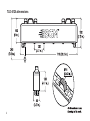
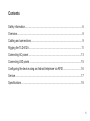
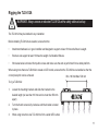
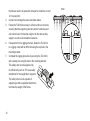
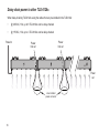
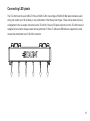
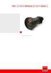
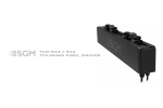
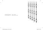
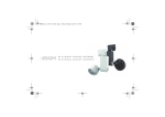
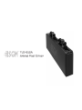
TLD-612A
Artnet Pixel Driver
TLD-612A dimensions
2
TLD-612A
USER MANUAL REV. 2
© 2014 SGMTM. Information subject to change without notice. SGM and all affiliated companies disclaim liability for any injury, damage, direct or indirect loss, consequential or
economic loss or any other loss occasioned by the use of, inability to use or reliance on
the information contained in this manual. The SGM logo, the SGM name and all other
trademarks in this document pertaining to services or products by SGM or its affiliates and
subsidiaries are trademarks owned or licensed by SGM or its affiliates or subsidiaries.
English edition
3
4
Contents
Safety information.................................................................................................... 6
Overview.................................................................................................................. 8
Cabling and connections.......................................................................................... 9
Rigging the TLD-612A.............................................................................................11
Connecting AC power............................................................................................. 13
Connecting LED pixels........................................................................................... 15
Configuring the device using an Android telephone via RFID................................ 16
Service................................................................................................................... 17
Specifications......................................................................................................... 18
5
Safety information
WARNING! Read the safety precautions in this section before
installing, powering or operating this product.
The TLD-612A is intended for professional use only. It is not suitable for household use.
Review the following safety precautions carefully before installing or operating the device.
Preventing electric shock
DANGER! Risk of electric shock. Do not open the device.
•
•
•
•
•
•
Do not open the device; there are no user-serviceable parts inside.
Ensure that power is cut off when wiring the device to the AC mains supply.
Ensure that the device is electrically connected to earth (ground).
Do not apply power if the device is in any way damaged.
Do not immerse the fixture in water or liquid.
Use only a source of AC power that complies with local building and electrical codes and has both overload and
earth leakage protection.
Never attempt to bypass the fuse. Always have defective fuses replaced with ones of the specified type and rating.
Verify that the power feed cable is rated for the total current draw of all daisy-chained products.
•
•
6
WARNING! Take measures to prevent personal injury.
•
•
•
•
•
Install only in a well-ventilated space.
Do not paint, cover, or modify the device.
Take precautions to prevent injury due to falls when working at height.
Ensure that the device is always securely fastened with suitable hardware.
For elevated installations, always comply with relevant load dimensioning and safety standards and
requirements.
7
Overview
The TLD-612A is an Artnet pixel driver that can be used to drive six SGM LT-100s, six SGM LT-200 or six strings of SGM
LED Ball pixel luminaries (each string can contain up to 56 led balls), or any combination of the three product types. Up
to five TLD-612As can be configured and controlled when daisy-chained together and connected to a computer using
an Ethernet cable, and up to five TLD-612A’s per port can be daisy-chained when one or more Ethernet switches are
used. TLD-612As can be configured using the SGM Artnet Configurator (available from http://www.sgmlight.com) and
controlled using a lighting controller or computer-based Artnet controller.
Unpack the device and inspect it to ensure that it has not been damaged in transport. The fixture is IP-65 rated. This
means that it is protected from ingress of dust and lower pressure jets of water from any direction.
A.
Mounting bracket left
B.
Mounting bracket right
C.
Cabinet
D.
Connections
E.
LED pixel outputs from 1 to 6 rows
(Illustrated by LED Balls)
8
Cabling and connections
9
The following connectors are used on the TLD-612A:
•
•
•
10
IP67-rated RJ45 Ethernet connectors, for artnet input and output.
3 lead power cable for power input and output with CEE cord caps.
6 x RJ765 output connectors supply 12V DC power and data to the LED products.
Rigging the TLD-612A
WARNING! Always secure an elevated TLD-612A with a safety cable as backup
The TLD-612A may be installed in any orientation.
Before installing TLD-612As at elevation, ensure that the:
•
Attachment hardware is in good condition and designed to support at least 10 times the fixture’s weight.
•
Structure can support at least 10 times the weight of all installed fixtures.
•
Work area below is blocked from public access and make sure the work is performed from a stable platform.
When using more than one TLD-612A to create an LED curtain, ensure that the TLD-612As are installed so that the
correct pixel pitch can be achieved.
Min. 160 mm/Max. 500 mm
To rig a TLD-612A:
1.
2.
3.
Loosen the mounting brackets and slide the brackets to the
desired length (no less than 160 mm and no more than 500 mm
apart)
Turn the thumb screws fully clockwise until the bracket is locked
in place.
When using more than one TLD-612A to form a wider LED curtain,
11
4.
5.
6.
7.
12
the fixtures need to be spaced 6 mm apart to obtain the correct
12 cm pixel pitch.
Connect and arrange the power and data cables.
Fasten the TLD-612A securely to a fixed surface or structure,
ensuring that the supporting structure and/or hardware used
can hold at least 10 times the weight of all the devices they
support, as well as all installed accessories.
If suspended from a rigging structure, fasten the TLD-612A
to a rigging clamp with an M10 bolt using the top hole in the
mounting bracket.
Complete the rigging procedure by securing the TLD-612A
with a safety wire using the hole in the mounting bracket.
This safety wire must be approved by
an official body such as TÜV as a safety
attachment for the weight that it supports.
The safety wire must be capable of
supporting a static suspended load that is
ten times the weight of the fixture.
6mm
Connecting AC power
The TLD-612A can operate on any 100–240 V, 50/60 Hz AC mains power supply.
Pre-mounted CEE connectors are for protection only and should be replaced with a connector that meets local
standards. For temporary installations, install a grounding-type (earthed) industrial 3-pronged type B plug that
complies with IEC 60309 or a comparable national standard and is rated 16 A minimum, and use corresponding power
outlet sockets. Follow the connector manufacturer’s instructions and all locally applicable laws and electrical safety
codes. For permanent installations, have a qualified electrician hard-wire the TLD-612A to the AC mains supply
The device must be grounded/earthed and be able to be isolated from AC power. The AC power supply must
incorporate a fuse or circuit breaker for fault protection.
13
Daisy-chain power to other TLD-612As
When daisy-chaining TLD-612As using the cables that are pre-installed in the TLD-612A:
•
@ 230VAC, 13A, up to 8 TLD-612As can be daisy-chained.
•
@ 115VAC, 13A, up to 4 TLD-612As can be daisy-chained.
Power in
Power
link out
Power
link out
Power
out
User installed
power connector
14
Connecting LED pixels
The TLD-612A can drive six SGM LT-100s, six SGM LT-200 or six strings of SGM LED Ball pixel luminaries (each
string can contain up to 56 led balls), or any combination of the three product types. These can be attached in any
arrangement to the six output connectors on the TLD-612A. The six LED pixel connectors on the TLD-612A are not
designed to bear loads. Always ensure that any attached LT-100s, LT-200s and LED Balls are supported by other
means than attachment to an TLD-612A connector.
15
Configuring the device using an Android telephone via RFID
As an alternative to connecting the device to power and using the SGM Artnet Configurator, one or more TLD612A devices can also be configured wirelessly, via RFID, using the SGM Tool app (available from the Google
Play Store) installed on an Android smart phone that has NFC support (ISO 15693 and ISO 18000-3 mode 1
compatible, operating on 13.56 MHz ±7k Hz carrier frequency).
16
Service
There are no user-serviceable components inside the device. Do not open the TLD-612A, as doing so is likely to
damage its ingress protection. Consult your SGM dealer if the device operates abnormally, is defective or otherwise
in need of service or repair.
Upgrading the firmware
We recommend that you to keep your device’s firmware current. Visit http://www.sgmlight.com to obtain the most upto-date firmware. To perform firmware updates, you need an SGM USB uploader cable (P/N 83062011), a Windowsbased personal computer and the SGM Artnet Configurator (available from http://www.sgmlight.com).
17
Specifications
PHYSICAL
Length x width x height .................................................................................. 715 x 80 x 182 mm (28.2 x 3.2 x 7.2 in.)
Weight........................................................................................................................................................4 kg (8.8 lbs)
CONSTRUCTION
Housing ......................................................................................................................................................... Aluminum
Finish ....................................................................................................................... Black electrostatic powder coating
INSTALLATION
Orientation................................................................................................................................................................ Any
Minimum distance to combustible materials.............................................................................................. 50 mm (2 in.)
Distance between adjacent TLD-612As (if pitch is to be maintained)....................................................................6 mm
AMBIENT OPERATING CONDITIONS
Maximum ambient temperature (Ta)....................................................................................................... 40° C (104° F)
Minimum ambient temperature (Ta)......................................................................................................... -10° C (14° F)
Operating humidity ............................................................................................................................................... 100%
IP rating ................................................................................................................................................................. IP 65
18
PROGRAMMING AND CONTROL
Configuration...................................................................................................via PC running SGM Artnet Configurator
Control of attached LED pixels........................................................ via Artnet with three DMX channels per LED pixel
Software upgrade .......................................................................................... via PC running SGM Artnet Configurator
Wireless interface............................. via RFID using an Android telephone that has NFC support and SGM Tools app
Firmware updates...................................................................................via SGM USB uploader cable (P/N 83062011)
CONNECTIONS
Artnet data input/output .......... 2 x IP67-rated Avnet Abacus RJ-45 female sockets (P/N: BENRJS-5EPFFJ-SC7002)
Pixel luminaire connections..................... 6 x RJ765 connectors, compatible with SGM LT-100, LT-200 and LED Balls
ELECTRICAL
AC power ..................................................................................................................................... 100–240 V, 50/60 Hz
Maximum total power consumption (full load)..................................................................................................... 320 W
Standby power ( with all outputs off)...................................................................................................................... 55 W
Maximum standby power (with no load)................................................................................................................... 5 W
FUSES
Main fuses (not user-replaceable).................................................................................................................... 2 x T12A
Power supply fuses (not user-replaceable)................................................................................................... 2 x T3.15A
19
TYPICAL POWER AND CURRENT
230 V, 50 Hz...............................................................................................................................310 W, 1.36 A, 0.99 PF
240 V, 50 Hz...............................................................................................................................310 W, 1.30 A, 0.99 PF
APPROVALS
Safety.......................................................................................................................................................... EN 60950-1
EMC....................................................................................................................................... EN 55103-1 , EN 55103-2
Specifications subject to change without notice
20
USER’S NOTES
21
22
23