1
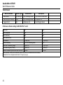
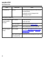
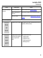
1, 2, 3, 4, and 5 Gas Detector
50105442-036
English
©BW Technologies 2013. All rights reserved.
Quick Reference Guide
GasAlertMicro 5/PID/IR
Table of Contents
Limited Warranty and Limitation Liability .............. 0
Contacting BW Technologies by Honeywell ......... 0
Introduction .............................................................. 1
Safety Information - Read First ............................... 1
Sensor Poisons and Contaminants ........................ 4
Parts of the GasAlertMicro 5/PID/IR ....................... 5
Display Elements ..................................................... 6
Pushbutton ............................................................... 7
Connecting the Gas Cylinder to the Detector ....... 7
Single Gas Calibration Cap ..........................................8
Removing the Cap .................................................... 8
Pump ......................................................................... 9
Identifying the Pump .....................................................9
Generation 1: 116885-L3 (yellow) and 118933-L3
(black) ....................................................................... 9
Generation 2: 130916-L3* (yellow) and 130917-L3
(black) ....................................................................... 9
Pump Features ...........................................................10
Pump Alarm ................................................................10
Confined Space Sampling ..........................................10
Maximum Hose Length when Confined Space
Sampling ................................................................. 11
Alarms ..................................................................... 15
User Options Menu ................................................ 18
Maintenance ........................................................... 19
Replacing Battery Cells and Packs ...................... 20
Replacing Alkaline Batteries .......................................21
Replacing Lithium Battery Packs ................................22
WEEE Directive and Battery Directive ........................22
Removal and Disposal of the Battery Pack............. 22
Removal and Disposal of the Coin Cell................... 23
Replacing a Sensor or Sensor Filter ...........................25
Replacing the Pump Filter (Generation 2 Pump
only) ............................................................................26
Replacing the Pump Nozzle (Generation 2 Pump
only) ............................................................................26
Specifications ......................................................... 27
Information Required for European Regulations
Compliance ............................................................. 30
Tested Sensors ....................................................... 32
Performance Data According to EN 45544 Part 1
and 2 ....................................................................... 32
Troubleshooting ..................................................... 33
Replacement Parts and Accessories ................... 39
Bump Test ............................................................... 12
Performing a Bump Test .............................................12
Calibration .............................................................. 13
i
Limited Warranty and Limitation Liability
BW Technologies LP (BW) warrants the product to be free from defects in material and workmanship under normal use and service for a period of
two years, beginning on the date of shipment to the buyer. This warranty extends only to the sale of new and unused products to the original buyer.
BW’s warranty obligation is limited, at BW’s option, to refund of the purchase price, repair or replacement of a defective product that is returned to
a BW authorized service center within the warranty period. In no event shall BW’s liability hereunder exceed the purchase price actually paid by the
buyer for the Product.
This warranty does not include:
a) fuses, disposable batteries or the routine replacement of parts due to the normal wear and tear of the product arising from use;
b) any product which in BW’s opinion, has been misused, altered, neglected or damaged, by accident or abnormal conditions of operation,
handling or use;
c) any damage or defects attributable to repair of the product by any person other than an authorized dealer, or the installation of unapproved
parts on the product; or
The obligations set forth in this warranty are conditional on:
a) proper storage, installation, calibration, use, maintenance and compliance with the product manual instructions and any other applicable
recommendations of BW;
b) the buyer promptly notifying BW of any defect and, if required, promptly making the product available for correction. No goods shall be
returned to BW until receipt by the buyer of shipping instructions from BW; and
c) the right of BW to require that the buyer provide proof of purchase such as the original invoice, bill of sale or packing slip to establish that the
product is within the warranty period.
THE BUYER AGREES THAT THIS WARRANTY IS THE BUYER ’S SOLE AND EXCLUSIVE REMEDY AND IS IN LIEU OF ALL OTHER WARRANTIES, EXPRESS OR IMPLIED,
INCLUDING BUT NOT LIMITED TO ANY IMPLIED WARRANTY OF MERCHANTABILITY OR FITNESS FOR A PARTICULAR PURPOSE. BW SHALL NOT BE LIABLE FOR ANY
SPECIAL, INDIRECT, INCIDENTAL OR CONSEQUENTIAL DAMAGES OR LOSSES, INCLUDING LOSS OF DATA, WHETHER ARISING FROM BREACH OF WARRANTY OR
BASED ON CONTRACT, TORT OR RELIANCE OR ANY OTHER THEORY.
Since some countries or states do not allow limitation of the term of an implied warranty, or exclusion or limitation of incidental or consequential
damages, the limitations and exclusions of this warranty may not apply to every buyer. If any provision of this warranty is held invalid or
unenforceable by a court of competent jurisdiction, such holding will not affect the validity or enforceability of any other provision.
Contacting BW Technologies by Honeywell
USA: 1-888-749-8878
Europe: +44(0) 1295 700300
Canada: 1-800-663-4164
Other countries: +1-403-248-9226
Email us at: [email protected]
Visit BW Technologies by Honeywell’s website at: www.gasmonitors.com
GasAlertMicro 5/PID/IR
Introduction
GasAlertMicro 5/PID/IR
Introduction
Safety Information - Read First
The quick reference guide provides basic information to operate
the GasAlertMicro 5, GasAlertMicro 5 PID, and GasAlertMicro 5
IR gas detectors. For complete operating instructions, refer to
the GasAlertMicro 5/PID/IR User Manual provided on the
CD-ROM.
Use the detector only as specified in this quick reference guide
and the user manual, otherwise the protection provided by the
detector may be impaired.
The GasAlertMicro 5, GasAlertMicro 5 PID, and
GasAlertMicro 5 IR detectors (“the detector”) are designed to
warn of hazardous gas levels above user-defined alarm
setpoints.
Read the following Cautions before using the detector.
Note
Unless reference is made to a specific detector
model, the GasAlertMicro 5, GasAlertMicro 5 PID,
and GasAlertMicro 5 IR detectors are referred to as
GasAlertMicro 5/PID/IR.
The detector is shipped with English as the default
displayed language. Additional languages provided
are French, German, Spanish, and Portuguese. The
screens for the additional languages are displayed on
the detector and in the corresponding quick reference
guide.
The detector is a personal safety device. It is your responsibility
to respond properly to the alarm.
a Cautions
• Warning: Substitution of components may impair
Intrinsic Safety.
• Caution: For safety reasons, this equipment must be
operated and serviced by qualified personnel only. Read
and understand the user manual completely before
operating or servicing.
• Charge the detector before first-time use. BW
recommends the detector be charged after every
workday.
• Charge the battery pack immediately when a low battery
alarm occurs.
• Read and adhere to the battery cautions provided in
Replacing Battery Cells and Packs on page 20.
1
GasAlertMicro 5/PID/IR
Quick Reference Guide
• BW recommends that the combustible sensor be
checked with a known concentration of calibration gas
after any exposure to contaminants/poisons such as
sulfur compounds, silicon vapors, halogenated
compounds, etc.
• BW recommends to bump test the sensors before each
day’s use to confirm their ability to respond to gas by
exposing the detector to a gas concentration that
exceeds the alarm setpoints. Manually verify that the
audible and visual alarms are activated. Calibrate if the
readings are not within the specified limits.
• For an additional bump test caution relating to the
European Regulations, refer to page 12.
• Calibrate the detector before first-time use and then on
a regular schedule, depending on use and sensor
exposure to poisons and contaminants. The sensors
must be calibrated regularly and at least once every
180 days (6 months).
• Calibrate only in a safe area that is free of hazardous
gas in an atmosphere of 20.9% oxygen.
• Only the combustible gas detection portion of this
instrument has been assessed for performance by CSA
International.
• The combustible sensor is factory calibrated to 50%
LEL methane. If monitoring a different combustible gas
in the % LEL range, calibrate the sensor using the
appropriate gas.
• Caution: High off-scale LEL readings may indicate an
explosive concentration.
2
• Protect the combustible sensor from exposure to lead
compounds, silicones, and chlorinated hydrocarbons.
Although certain organic vapors (such as leaded
gasoline and halogenated hydrocarbons) may
temporarily inhibit sensor performance, in most cases,
the sensor will recover after calibration.
• For use only in potentially explosive atmospheres
where oxygen concentrations do not exceed 20.9%
(v/v). Oxygen deficient atmospheres (<10% v/v) may
suppress some sensor outputs.
• Any rapid up scaling reading followed by a declining or
erratic reading may indicate a gas concentration
beyond the upper scale limit, which can be hazardous.
• Extended exposure of the GasAlertMicro 5,
GasAlertMicro 5 PID, or GasAlertMicro 5 IR to certain
concentrations of combustible gases and air may stress
the detector element that can seriously affect its
performance. If an alarm occurs due to a high
concentration of combustible gases, recalibration
should be performed or, if needed, the sensor replaced.
• The BW pump module (M5-PUMP) is certified for use
with the GasAlertMicro 5, GasAlertMicro 5 PID, and
GasAlertMicro 5 IR models only.
• Protect the PID sensor from exposure to silicone
vapors.
• When calibrating O3 and ClO2 sensors that are located
in the Toxic 2 position of the detector, a single gas
calibration cap must be used to ensure accurate
calibration.
GasAlertMicro 5/PID/IR
Safety Information - Read First
• Replace the sensors only in a safe and non-hazardous
area that is free of hazardous gas in an atmosphere of
20.9% oxygen.
• Warning: The battery pack (M5-BAT08) is equipped with
a lithium battery that may present a risk of fire or
chemical burn hazard if misused. Do not disassemble,
heat above 212ºF (100ºC), or incinerate.
• Warning: Do not use any other lithium batteries that are
not designed for use with the GasAlertMicro 5,
GasAlertMicro5 PID, or GasAlertMicro5 IR detectors.
Use of any other cell can cause fire and/or explosion. To
order and replace the M5-BAT07 or the M5IR-BAT08
lithium battery pack, contact BW Technologies by
Honeywell.
• Warning: Lithium polymer cells exposed to heat at
266°F (130°C) for 10 minutes can cause fire and/or
explosion.
• Dispose of used lithium cells immediately. Do not
disassemble and do not dispose of in fire. Do not mix
with the solid waste stream. Spent batteries must be
disposed of by a qualified recycler or hazardous
materials handler.
• Keep lithium cells away from children.
• Before using common products around sensors, refer
to Sensor Poisons and Contaminants on page 4.
• High concentrations of certain toxic gases, for example
H2S, may have an adverse effect on the LEL sensor.
This effect, known as inhibition, is usually temporary
but in extreme circumstances can impair the sensitivity
of the LEL sensor.
After any gas exposure that causes an alarm in the toxic
gas sensors, the LEL sensor should be verified with a
bump test, and recalibrated if necessary.
The detector contains either alkaline batteries or a lithium
polymer battery. Refer to the following warnings.
ce Warning
This instrument contains alkaline batteries. Do not mix
with the solid waste stream. Spent batteries must be
disposed of by a qualified recycler or hazardous materials
handler.
ce Warning
This instrument contains a lithium polymer battery.
Dispose of lithium cells immediately. Do not disassemble
and do not dispose of in fire. Do not mix with the solid
waste stream. Spent batteries should be disposed of by a
qualified recycler or hazardous materials handler.
3
GasAlertMicro 5/PID/IR
Quick Reference Guide
Sensor Poisons and Contaminants
Several cleaners, solvents, and lubricants can contaminate and
cause permanent damage to sensors. Before using cleaners,
solvents, and lubricants in close proximity to the detector
sensors, read and adhere to the following caution and table.
a Caution
Use only the following BW Technologies by Honeywell
recommended products and procedures:
• Use water based cleaners.
• Use non-alcohol based cleaners.
• Clean the exterior with a soft, damp cloth.
• Do not use soaps, polishes, or solvents.
4
The following table lists common products to avoid using
around sensors.
Cleaners and
Lubricants
• Brake cleaners
• Lubricants
• Rust inhibitors
• Window and glass
cleaners
• Dishsoaps
• Citrus based
cleaners
• Alcohol based
cleaners
• Hand sanitizers
• Anionic detergents
• Methanol (fuels and
antifreezes)
Silicones
Aerosols
• Silicone based
adhesives, sealants, and
gels
• Hand/body and
medicinal creams
containing silicone
• Tissues containing
silicone
• Mold releasing agents
• Polishes
• Bug
repellents
and sprays
• Lubricants
• Rust
inhibitors
• Window and
glass
cleaners
GasAlertMicro 5/PID/IR
Parts of the GasAlertMicro 5/PID/IR
Parts of the GasAlertMicro 5/PID/IR
Item
Description
1
Liquid crystal display (LCD)
2
Pushbuttons
3
Audible alarms
4
Toxic 2 sensor
5
Toxic 1/PID sensor (GasAlertMicro 5 PID), or
Toxic 1/IR (CO2) sensor (GasAlertMicro 5 IR)
6
Visual alarm indicators (LEDs)
7
LEL sensor
8
Oxygen sensor
9
Pushbuttons
10
Battery pack
11
Alligator clip
5
GasAlertMicro 5/PID/IR
Quick Reference Guide
Display Elements
Item
6
Description
1
Alarm condition
2
Automatically span sensor
3
Gas cylinder
4
Gas identifier bars
5
Battery life indicator
6
Passcode lock
7
Data transmission
8
Clock
9
Stealth mode
10
Optional pump indicator
11
Datalog card indicator (optional)
12
Alarm condition (low, high, TWA, STEL, or
multi) or view TWA, STEL and peak (MAX)
gas exposures
13
Automatically zero sensor
GasAlertMicro 5/PID/IR
Pushbutton
Pushbutton
Pushbutton
Connecting the Gas Cylinder to the Detector
Description
A
• To activate the detector, press A.
• To deactivate the detector, press and hold
A until the countdown is complete.
G
• To increment the displayed value or scroll
up, press G.
• To enter the user option menu, press G
and H simultaneously and hold until the
countdown is complete.
• To clear the TWA, STEL, and peak (MAX)
gas exposure readings, press C and G
simultaneously and hold until the
countdown is complete.
• To view the date and time, alarm setpoints
(TWA, STEL, low, and high) of all sensors,
and the LEL correction factor (if
applicable), press G.
H
• To decrement the displayed value or scroll
down, press H.
• To initiate calibration and setting alarm
setpoints, press C and H simultaneously
and hold until the countdown is complete.
C
• To view the TWA, STEL, and peak (MAX)
readings, press C.
• To acknowledge latched alarms, press C.
7
GasAlertMicro 5/PID/IR
Quick Reference Guide
Single Gas Calibration Cap
a Caution
2.
Connect the calibration hose to the gas cylinder and
to the intake inlet on the cap.
If an O3 or ClO2 sensor is located in the Toxic 2 sensor
position, a single gas calibration cap must be used to
ensure accurate calibration.
Only use the single gas calibration cap during the
calibration process.
To calibrate O3 and ClO2 sensors using the single gas
calibration cap, refer to the following procedures and
illustrations.
1. Insert the cap into the Toxic 2 sensor position on the
detector. Press firmly until the release tabs click.
Note
The arrow on the cap indicates the direction of gas
flow from intake to outtake.
Removing the Cap
Using your thumb, push forward against both the inlet and
outlet simultaneously to remove the cap from the detector.
8
GasAlertMicro 5/PID/IR
Pump
Pump
Identifying the Pump
When using the pump module, attach it and the pump
accessories prior to activating the detector.
There are two generations of pump. The best way to
differentiate the Generation 2 pump from the Generation 1
pump is the inline filter that is visible on the Generation 2 pump
on the left-hand side.
For more information on the pump, refer to the
GasAlertMicro 5/PID/IR User Manual.
a Warning
If the pump module is installed on the detector, the
following three things must occur during start-up. If any
one of the conditions below does not occur, discontinue
use of the detector and contact BW Technologies by
Honeywell immediately.
• The detector prompts for a pump test during start-up
• The pump module passes the pump test at start-up
when the pump inlet or sample chain inlet is blocked
• The J icon displays on the LCD
To ensure accurate gas detection, the sensors must be
calibrated immediately when the pump module is
replaced by the diffusion cap and vice versa.
When using the sample probe at -10°C to +0°C (14°F to
32°F), keep the sample probe in your hand.
Each model of pump has different operating specifications.
Refer to Maximum Hose Length when Confined Space
Sampling on page 11.
Generation 1: 116885-L3
Generation 2: 130916-L3*
(yellow) and 118933-L3
(yellow) and 130917-L3
(black)
(black)
a Caution
A demand flow regulator must be used to manually
calibrate the GasAlertMicro 5/PID/IR detector when the
pump module is installed.
The calibration cap is designed for use with the diffusion
cap only. It cannot be used with the pump module.
*Note
Performance approved conditions
9
GasAlertMicro 5/PID/IR
Quick Reference Guide
Pump Features
To replace the pump filter and pump nozzle for the Generation 2
pump, refer to Replacing the Pump Filter (Generation 2 Pump
only) on page 26 and Replacing the Pump Nozzle (Generation
2 Pump only) on page 26.
To replace the pump filter for the Generation 1 pump, refer to
the GasAlertMicro 5/PID/IR User Manual. The pump nozzle
cannot be replaced.
If the pump test is successful, the detector returns to normal
operation, otherwise the pump alarm continues. If the pump
alarm persists, refer to the Pump Operation Troubleshooting in
the guide or in the Pump Operation section in Troubleshooting
in the GasAlertMicro 5/PID/IR User Manual.
Confined Space Sampling
To measure hazardous gas in a confined space, refer to the
following illustration and steps 1-5.
Pump Alarm
The external pump draws air over the sensors continually. If the
pump stops operating or becomes blocked, the detector
activates the pump alarm and the pump alarm latches. The
following screens display.
a Caution
Ensure the blockage is cleared before pressing C to
acknowledge the latched pump alarm.
When C is pressed, the detector automatically launches a
pump test to reset the pump module.
10
The detector and pump module can also be used with a
sintered filter.
GasAlertMicro 5/PID/IR
Pump
a Warning
To measure hazardous gas in a confined space, the
sample probe must be used with the pump module.
a Caution
To prevent the teflon lining inside the Tygon tubing from
causing a blockage when connecting it to the sample
probe, the end of the tubing must be flared. Refer to
steps 2 and 3.
1. Attach the pump connector end of the teflon-lined
Tygon tubing to the pump module.
2. Gently insert needle nose pliers into the other end of
the teflon-lined Tygon tubing. Using a circular motion,
flare the end of the tubing.
3. Connect the flared end of the tubing to the sample
probe. Ensure the teflon-lining does not separate
from the Tygon tubing, as it will block the tube and
generate a pump alarm.
4. Activate the detector. Ensure all connections are
secure before sampling.
5. Insert the sample probe into the confined space.
a Warning
Depending upon the length of the tubing and the type of
gas in the confined space, allow a minimum of 3 seconds
per foot of tubing to ensure the readings stabilize before
entering the area.
Example: 10 ft. = 30 seconds
Maximum Hose Length when Confined Space Sampling
Maximum sample hose length is dependent on pump model,
operating temperature, and sampling accessory. Refer to the
tables below.
a Caution
Maximum sample hose length is dependent on an inner
1/16” hose diameter.
Table 1. Generation 1 Pump
-10°C to +0°C
(14°F to 32°F)
0°C to 50°C
(32°F to 122°F)
Sintered filter
3 m (10 ft.)
9.1 m (30 ft.)
Sample Probe
3 m (10 ft.)
3 m (10 ft.)
a Warning
When using the sample probe at -10°C to +0°C (14°F to
32°F), keep the sample probe in your hand.
Table 2. Generation 2 Pump
-20°C to 50°C(-4°F to 122°F)
Sintered filter
20 m (66 ft.)
Sample Probe
3 m (10 ft.)
Note
The Sample Probe/Generation 2 Pump combination
was tested by BAM.
11
GasAlertMicro 5/PID/IR
Quick Reference Guide
Bump Test
Note
A bump test is the process of applying a small amount of test
gas to force the detector into alarm. A bump test should be
performed regularly to confirm the sensors are responding
correctly to gas, and that the audible, visual, and vibrator
alarms activate during an alarm condition. Calibrate if the
readings are not within specified limits.
Performing a Bump Test
a Caution
BW recommends to bump test the sensors before each
day’s use to confirm their ability to respond to gas by
exposing the sensors to a gas concentration that exceeds
the alarm setpoints.
Should the user wish to comply with European
Regulations, a bump test must be completed before each
day’s use. Refer to EN 60079-29-2.
To perform a manual bump test refer to Connecting the Gas
Cylinder to the Detector on page 7 and the following steps 1-6.
Follow this procedure when Bump Daily is enabled.
Note
If performing a bump test on a pump unit, connect the
calibration hose directly to the pump module.
1. Connect the calibration hose to the 0.5l/min regulator
on the gas cylinder.
12
Only use the calibration cap for bump tests and
calibrations.
2. Connect the calibration hose to the intake inlet on the
calibration cap. Arrows on the calibration cap indicate
the direction of gas flow.
3. Attach the calibration cap and tighten the knob.
Refer to Connecting the Gas Cylinder to the Detector
on page 7.
Note
Ensure the knob is securely fastened before applying
gas. Do not overtighten the calibration cap. Ensure
strong air currents are kept away from the exhaust
side of the calibration cap, as this can affect the bump
test accuracy.
4. Apply gas. Verify the visual, audible, and vibrator
alarms activate.
5. Close the regulator and remove the calibration cap
from the detector. The detector will temporarily
remain in alarm until the gas clears from the sensors.
6. Disconnect the calibration hose from the cap and
regulator.
GasAlertMicro 5/PID/IR
Calibration
Calibration
Calibrate only in a safe area in an
atmosphere of 20.9% oxygen.
1. Activate the detector. To enter calibration,
press and hold C and H
simultaneously. The detector beeps and
flashes to the corresponding countdown.
The LCD then displays Starting
calibration.
2.
flashes while the detector
zeros all of the sensors (except CO2) and
calibrates the oxygen sensor. If a sensor
fails to auto zero, that sensor will bypass
the span.
If calibrating a GasAlertMicro 5 or
GasAlertMicro 5 PID, proceed to step #4.
Step #3 for Micro 5 IR Only
3. The Zero-CO2? screen displays. Press
C to zero the CO2 sensor, or press A to
bypass.
If C is pressed to zero the CO2 sensor,
the following screens display:
- Apply CO2 zero gas now (nitrogen
must be used to zero the CO2 sensor).
5. The following three screens display:
- Apply span gas now to calibrate
- or press C to select sensor(s)
- or press A to skip calibration
If none of the buttons are pressed,
proceed to step #6.
If C is pressed, proceed to step #5.
If A is pressed, proceed to the end of
step #7.
6. Select which sensor to span. Press G
or H to scroll to the required sensor
and then press C to select. Sensors
must be spanned in the following order:
- Exotics (NH3, ClO2, O3, and CO2)
- Single gases
- Quad gases (H2S, CO, O2 and LEL).
7. Attach the calibration cap and apply gas
at a flow rate of 500 ml/min.
K flashes while the detector determines
which gas is being applied.
After 30 seconds,
flashes and
a countdown displays while the detector
completes the span.
4. - The Auto-Zero CO2 screen displays,
and
flashes.
13
GasAlertMicro 5/PID/IR
Quick Reference Guide
8. When the span is complete, the following
three screens display:
- Calibration successful
- Press G to apply a new cal gas
- Press H to end span
Repeat steps #4-7 to calibrate the
remaining sensors.
The LCD displays the following options:
- Press C to set the calibration due
dates or press A to bypass.
9. Press G or H to change the calibration
due date. Press C to accept the value
and proceed to the next due date. If a
sensor fails or does not span, the
calibration due date cannot be changed
for that sensor.
The LCD displays the following options:
- Press C to change the calibration due
dates or press A to bypass.
10.Press G or H to change the alarm
setpoint. Press C to save the value and
proceed to the next setpoint.
Define the remaining setpoints. The
detector beeps twice when all of the
alarm setpoints have been defined or
bypassed.
14
11.When calibration is complete, Saving
calibration displays.
Note
Only use the calibration cap and single
gas calibration cap during calibration and
bump tests.
For additional information about performing calibrations and
bump tests, refer to the GasAlertMicro 5/PID/IR User Manual.
GasAlertMicro 5/PID/IR
Alarms
Alarms
Refer to the following table for information about alarms and corresponding screens. During an alarm condition, the backlight
activates and the LCD displays the ambient gas readings.
Alarm
Screen
Alarm
Low Alarm
TWA Alarm
•
•
•
•
•
•
•
•
Fast beep
Slow flash
L and target gas bar flash
Vibrator alarm activates
Fast beep
Slow flash
L and target gas bar flash
Vibrator alarm activates
High Alarm
STEL Alarm
•
•
•
•
•
•
•
•
Constant beep
Fast flash
L and target gas bar flash
Vibrator alarm activates
Screen
Constant beep
Fast flash
L and target gas bar flash
Vibrator alarm activates
15
GasAlertMicro 5/PID/IR
Quick Reference Guide
Alarm
Screen
Alarm
Multi Alarm
Over Limit (OL) Alarm
• Alternating low and high alarm beep
and flash
• L and target gas bars flash
• Vibrator alarm activates
• Fast beep and flash
• L and target gas bar flash
• Vibrator alarm activates
Sensor Alarm
Automatic Deactivation Alarm
• One beep every 15 seconds
• Eight beeps and flashes
• FAIL flashes above the failed sensor
•
displays
• Vibrator alarm temporarily activates
• Battery depleted screen displays and
the detector deactivates
Low Battery Alarm
Normal Deactivation
• One beep and two flashes every
25 seconds
• Three beeps and flashes
•
flashes
a Caution
Charge the battery immediately when
a low battery alarm occurs.
16
Screen
GasAlertMicro 5/PID/IR
Alarms
Alarm
Screen
Alarm
Confidence Beep
Pump Alarm
• One beep, one flash, and one
vibration every 10 seconds
• Screen flashes:
- Pump flow change detected
- Check for blocked inlet
Note
The Confidence Beep option is
automatically disabled during a
low battery alarm.
Screen
- or press C to run a pump test
• Two fast beeps and alternating flashes
• Vibrator alarm activates
• L and J flash
MMC Fail Alarm
• One beep every 5 seconds
•
flashes
Note
If enabled, during an alarm condition the Latch (latching alarms) option causes the low and high gas alarms (audible, visual, and
vibrator) to persist until the alarm is acknowledged by pressing C and the gas concentration is below the low alarm setpoint.
The peak concentrations display continually until the alarm condition no longer exists. Local regulations may require the Latch
option be enabled.
To comply with European Regulations, the Latch option must be enabled.
17
GasAlertMicro 5/PID/IR
Quick Reference Guide
User Options Menu
To access the user options, press and hold G and H
simultaneously until the detector completes the countdown. To
scroll through the options press G or H. Press C to select the
option. The following options are available.
Exit: Exits the user options menu.
User Options:
• Backlght (backlight): Enables/disables the automatic
backlight in low-light conditions.
• Confibeep (confidence beep): If enabled, the confidence
beep provides continuous confirmation that the detector is
operating correctly (audible beep every 10 seconds).
• Due-lock (calibration user lockout): If enabled, upon
startup a passcode is required to operate a detector that is
overdue for calibration.
• Latch (latched alarm): Enable to ensure an alarm persists
until it is acknowledged (press C to acknowledge).
• Passcode (passcode protection): Enable to prevent
unauthorized personnel from accessing the user options
menu, calibration function, and alarm setpoint adjust
function.
• Safe (safe mode): If enabled, Safe displays continuously
on the LCD unless an alarm condition occurs.
• Language: Displays the LCD screens in English, Français
(French), Deutsch (German), Español (Spanish), or
Português (Portuguese).
Note
The detector is shipped displaying English as the
default language.
18
Sensors:
• Sens on (sensor enabled): Enables/disables a sensor (the
detector continues to operate if a sensor is disabled).
a Warning
Use extreme caution when disabling a sensor. The
disabled sensor cannot detect and alarm against the
applicable gas.
• Span gas: Define the span gas concentration for each
sensor (must match the gas concentration on the gas
cylinder).
• Stel period (Short Term Exposure Limit): The short term
exposure limit (STEL) provides protection for workers from
over exposure to high concentrations of gas, and is based
on user-defined 5-15 minute intervals.
When the maximum STEL is reached, the detector alarms
to notify the worker. Set the STEL period from
5-15 minutes (applicable to toxic sensors only).
• TWA method (Time Weighted Average): This option is a
safety measure that calculates the accumulated averages
of gases to warn the worker when the maximum average
has accumulated. Select one of the following options:
- OSHA Method: 8 hour moving average—oldest value
(first hour) is replaced by the newest value (ninth hour).
- ACGIH Method: Infinite accumulated average to 8 hours
- total accumulation, whether it is 2 hours or 8 hours.
• Resolution: Defines the resolution of the gas
measurement as either regular or extra (if applicable).
GasAlertMicro 5/PID/IR
Maintenance
• %vol CO2: Enable to display the carbon dioxide (CO2)
reading as %vol.
• %vol CH4: Enable to display the LEL readings as %vol
assuming a methane environment.
Note
If changing the measurement unit from % LEL to %
Vol. or from % Vol. to % LEL, a calibration must be
completed and the alarm setpoints changed. For
calibration information refer to Calibration on page 13
and for alarm setpoint information refer to Alarm
Setpoints in Calibration Procedure in the
GasAlertMicro 5/PID/IR User Manual.
• Correction Factor (%): Enter a compensation factor for
hydrocarbons other than methane. The factor can only be
applied if the LEL sensor has been calibrated with
methane (LEL only). Detector operation using LEL
correction factors has not been tested by BAM.
• Autocal (automatic oxygen calibration): Enable/disable the
detector to automatically calibrate the oxygen sensor
during startup.
Maintenance
To maintain the detector in good operating condition, perform
the following basic maintenance as required.
• Calibrate, bump test, and inspect the detector on a regular
schedule.
• Maintain an operations log of all maintenance, bump tests,
calibrations, and alarm events.
• Clean the exterior with a soft damp cloth. Do not use
solvents, soaps, or polishes. Refer to Sensor Poisons and
Contaminants on page 4.
• Do not immerse the detector in liquids.
Logger (Datalogging): Define how often the detector records a
datalog sample (once every 1 to 127 seconds).
Clock: Define the date and time for the detector.
19
GasAlertMicro 5/PID/IR
Quick Reference Guide
Replacing Battery Cells and Packs
a Warning
To avoid personal injury and/or property damage, adhere
to the following battery cautions:
• Replace the alkaline cells or rechargeable battery pack
immediately when the detector emits a low battery
alarm.
• Use only batteries that are recommended by
BW Technologies by Honeywell.
• Use only approved alkaline batteries that are properly
installed in the battery pack. Refer to Specifications.
• To order lithium battery packs (M5-BAT08/M5-BAT07),
contact BW Technologies by Honeywell.
• Charge the batteries and battery packs using only a
recommended BW charger. Failure to adhere to this
caution can lead to fire and/or explosion.
• The detector must be deactivated to charge the battery
pack.
• Do not calibrate the detector immediately after charging is
complete.
• Both the lithium battery pack and the alkaline battery pack
are user-changeable in hazardous locations, but the
alkaline battery cells inside the pack can only be replaced
in a safe area that is free of hazardous gas.
• Warning: The M5-BAT08 and M5-BAT07 battery packs are
equipped with lithium batteries that can present a risk of
20
•
•
•
•
fire or chemical burn hazard if misused. Do not recharge,
disassemble, heat above 212°F (100°C), or incinerate.
Warning: Do not use any other lithium batteries with the
GasAlertMicro 5, GasAlertMicro 5 PID, and
GasAlertMicro 5 IR detectors. Use of any other cell can
cause fire and/or explosion.
Warning: Lithium polymer cells exposed to heat at 266°F
(130°C) for 10 minutes can cause fire and/or explosion.
Dispose of used lithium cells immediately. Do not
disassemble and do not dispose of in fire. Do not mix with
the solid waste stream. Spent batteries must be disposed
of by a qualifies recycler or hazardous materials handler.
Keep lithium cells away from children.
GasAlertMicro 5/PID/IR
Replacing Battery Cells and Packs
Replacing Alkaline Batteries
a Warning
Always deactivate the detector before removing the
battery pack. The battery packs are user-changeable in
hazardous locations, but the alkaline battery cells inside
the pack must be changed in a safe area that is free of
hazardous gas.
To charge the rechargeable battery pack, refer to the
GasAlertMicro 5/PID/IR Battery Charger User Manual.
To replace the alkaline batteries, refer to the following
procedures and illustration.
1. Press and hold C to deactivate the detector.
2. Open the latch on the bottom of the detector.
3. Remove the battery pack by lifting the bottom of the
pack upward from the detector.
4. On the battery pack, unscrew the two captive screws
and open.
5. Replace the three alkaline battery cells.
6. Replace the cover and reinsert the two captive
screws.
7. Replace the battery pack on the detector.
8. Close the latch.
21
GasAlertMicro 5/PID/IR
Quick Reference Guide
Replacing Lithium Battery Packs
a Warning
Do not disassemble the lithium battery pack. Read and
adhere to the cautions in Replacing Battery Cells and
Packs.
To replace the lithium battery pack, refer to the following
illustration and steps 1-4.
1.
2.
3.
4.
5.
Press and hold C to deactivate the detector.
Open the latch on the bottom of the detector.
Remove the battery pack by lifting the bottom of the
pack upward from the detector.
Replace the battery pack with a fully charged lithium
battery pack.
Close the latch.
WEEE Directive and Battery Directive
Failure to comply with the following battery removal and
disposal instructions may result in battery shorting, battery
leakage, and/or other damage. Ensure a qualified technician
completes the following procedures.
Removal and Disposal of the Battery Pack
Only a qualified technician should complete the following
procedures.
To remove the alkaline batteries, refer to steps #1 to #4 in
Replacing Alkaline Batteries on page 21.
To remove the lithium battery pack, refer to steps #1 and #2 in
Replacing Lithium Battery Packs on page 22.
Dispose of the battery pack according to local laws.
22
GasAlertMicro 5/PID/IR
Replacing Battery Cells and Packs
Removal and Disposal of the Coin Cell
Item
Description
1
Diffusion cap
2
Sensor filter
3
Sensors
4
Front shell
5
Sensor board
6
Back shell
7
Machine screws (for
diffusion cap)
8
Battery pack
9
Datalog card
10
Machine screws (for
rear shell)
23
GasAlertMicro 5/PID/IR
Quick Reference Guide
The detector contains a coin cell to power the real-tlime clock.
Only a qualified technician should complete the following
procedure.
1. Press and hold C to deactivate the detector.
2. Open the latch on the bottom of the detector.
3. Remove the battery pack by lifting the bottom of the
pack upward from the detector.
4. Remove the MMC card.
5. Remove the two machine screws on the rear shell
and then remove the diffusion cap or pump module.
6. Remove the sensors.
7. Remove the four machine screws in the battery pack
cavity.
8. Remove the rear shell.
9. The coin cell sits on the sensor board.
Gently remove the sensor board.
10. The coin cell is connected to the board by four leads.
Clip the four leads individually to remove the coin cell.
11. Dispose of the coin cell according to local laws.
a Caution
Do not touch two or more leads while disconnecting the
coin cell.
24
Note
Image above shows three of the four battery leads
that must be clipped.
GasAlertMicro 5/PID/IR
Replacing Battery Cells and Packs
Replacing a Sensor or Sensor Filter
To replace a sensor or sensor filter, refer to the following
illustration, table, and steps 1-7.
a Warning
To avoid personal injury and/or property damage, only
use sensors that are specifically designed for the
detector.
Replace the sensors in a non-hazardous area.
Note
Detectors that are configured for 1, 2, or 3 gases may contain
a dummy sensor in one of the four sensor locations.
1. Deactivate the detector.
2. Remove the two machine screws on the rear shell
and then remove the sensor cover or pump module
cover.
3. Remove the sensor filter and/or sensor(s).
4. Insert the new filter and/or sensor(s). Ensure the
sensor posts are aligned correctly.
5. Re-assemble the detector.
6. If the sensor is replaced with a different type of
sensor (e.g. SO2 to an H2S), the detector must be
reconfigured. Refer to Sensors in the Tech Mode
section of the GasAlertMicro 5/PID/IR User Manual.
7. Activate the detector and then calibrate the new
sensor(s). Refer to Calibration.
Item
Description
1
Sensor cover
2
Sensor filter
3
Sensors
4
Detector
5
Machine screws (2)
25
GasAlertMicro 5/PID/IR
Quick Reference Guide
Replacing the Pump Filter (Generation 2 Pump only)
Note
If replacing the pump filter on the Generation 1 pump,
refer to the GasAlertMicro 5/PID/IR User Manual.
1. Deactivate the detector.
2. Remove the filter window screw and the filter window.
3. Remove the old filter.
4. Important! Ensure the filter cavity and filter window
are clean and free of debris. Insert a new filter.
5. Replace the filter window and screw.
26
Replacing the Pump Nozzle (Generation 2 Pump only)
Note
If the nozzle is damaged, replace it immediately to
ensure accurate pump flow.
Only the Generation 2 pump has a replaceable
nozzle.
1. Deactivate the detector.
2. Gently insert a medium sized flathead screwdriver
into the nozzle slot. Lift and remove the damaged
nozzle.
3. Insert the new nozzle. Ensure the nozzle post inserts
correctly into the nozzle gasket.
GasAlertMicro 5/PID/IR
Specifications
Specifications
Instrument dimensions: 14.5 x 7.4 x 3.8 cm
(5.7 x 2.9 x 1.5 in.)
Weight: 370 g (13.1 oz.)
Operating and storage conditions:
Temperature:
VOC: -10°C to +40°C (14°F to +104°F)
Other gases: -20°C to +50°C (-4°F to +122°F)
Combustible gas sensor: Certified by CSA International to ±3%
LEL accuracy from -10°C to +40°C (4°F to 104°F)
Operating temperature tested by BAM:
-20°C to +50°C
Storage temperature as tested by BAM:
-25°C to +60°C (BAM evaluated the product from the storage
temperature of -25°C to +60°C)
Operating humidity:
O2: 0% to 99% relative humidity (non-condensing)
VOC: 0% to 95% relative humidity (non-condensing)
Combustibles: 5% to 95% relative humidity (non-condensing)
Cl2: 10% to 95% relative humidity (non-condensing)
HCN, ClO2: 15% to 90% relative humidity (non-condensing)
Other gases: 15% to 90% relative humidity (non-condensing)
Operating humidity as tested by BAM:
5% r.H. to 95% r.H.
Pressure: 95 to 110 kPa
Operating pressure as tested by BAM:
80 kPA to 120 kPa
Dust and moisture ingress: IP65/66
Alarm setpoints: May vary by region and are user-defined
Detection range:
O2: 0 - 30.0% vol. (0.1% vol. increments)
CO: 0 - 999 ppm (1 ppm increments)
CO (TwinTox sensor): 0 - 500 ppm (1 ppm increments)
H2S: 0 - 500 ppm (1 ppm increments)
H2S TwinTox sensor): 0 - 500 ppm (1 ppm increments)
Combustible (LEL): 0 - 100% LEL (1% LEL increments) or
0 - 5.0% v/v methane; certified by CSA International to C22.2
No. 152 and ISA 12.13.01 within 0 - 60% or 3.0% v/v methane
PH3: 0 - 5.0 ppm (0.1 ppm increments)
SO2: 0 - 150 ppm (1 ppm increments)
Cl2: 0 - 50.0 ppm (0.1 ppm increments)
NH3: 0 - 100 ppm (1 ppm increments)
NO2: 0 - 99.9 ppm (0.1 ppm increments)
HCN: 0 - 30.0 ppm (0.1 ppm increments)
ClO2: 0 - 1.00 ppm (1.00 ppm increments)
O3: 0 - 100 ppm (0.01 ppm increments)
VOC: 0 - 1000 ppm (1.0 ppm increments)
CO2 IR: 0 - 50,000 ppm (50 ppm increments) or 0-5.0% v/v CO2
(Sensors not certified for use with the GasAlertMicro 5 IR:
ClO2, HCN, NO2, PH3, Cl2)
Sensor type:
H2S/CO: Twin plug-in electrochemical cell
Combustibles: Plug-in catalytic bead
VOC: Photoionization detector (PID)
27
GasAlertMicro 5/PID/IR
Quick Reference Guide
CO2: IR detector
Other gases: Single plug-in electrochemical cell
O2 measuring principle: Capillary controlled concentration
sensor
Alarm conditions: TWA alarm, STEL alarm, low alarm, high
alarm, multi alarm, over limit (OL) alarm, sensor alarm, pump
alarm, MMC/SD fail alarm, low battery alarm, confidence beep,
automatic deactivation alarm
Audible alarm: 95 dB at 0.3 m (1 ft.) variable pulsed dual
beepers
Visual alarm: Dual red light-emitting diodes (LEDs)
Display: Alphanumeric liquid crystal display (LCD)
Backlight: Activates briefly during startup, when there is
insufficient light to view the display (if enabled), and during
alarm conditions
Self-test: Initiated during activation
Calibration: Automatic zero and automatic span
Oxygen sensor: Automatic span during startup (if enabled)
User field options: Confidence beep, latching low and high
alarms, passcode protection, enable/disable safe display mode,
combustible sensor measurement, sensor enable/disable,
language selection, enable/disable automatic O2 calibration, set
span concentration values, set STEL calculation period, set
TWA method, gas measurement resolution, enable/disable
automatic backlight, adjust clock/calendar, set datalogging rate
(datalog models only), CO2 sensor measurement
28
Datalog Models:
Approved for GasAlertMicro 5 and GasAlertMicro 5 PID
Models: Delkin 128 MB SD card and 64 MB Unigen SD card
Approved for GasAlertMicro 5 IR Models: Delkin 128 MB
MMC, Delkin 128 MB SD card, Transcend 128 MB SD, and
64 MB Unigen SD card
Battery operating time:
Toxic, O2, and LEL sensor configuration: Three alkaline cells
or one lithium battery pack at 20°C/68°F provides 20 hours
operating runtime
Toxic, O2, LEL, and PID sensor configuration: Three alkaline
cells or one lithium battery pack at 20°C/68°F provides 15 hours
operating runtime
Toxic, O2, LEL, and CO2 sensor configuration: Three
alkaline cells or one lithium battery pack at 20°C/68°F provides
15 hours operating runtime
M5-BAT08 battery operating time (as tested by BAM):
Toxic, O2, LEL, and CO2 sensor configuration: 11 hours
Approved Batteries:
Approved batteries for GasAlertMicro 5, GasAlertMicro 5
PID, and GasAlertMicro 5 IR product:
Alkaline (M5-BAT02): as per standards EN 60079-11,
EN 60079-0, UL913, CSA C22.2 No. 157
Lithium-ion polymer (M5-BAT07), as per standards
EN 60079-11, EN 60079-0, UL913, CSA C22.2 No. 157
Lithium-ion polymer (M5-BAT08): as per standards
EN 60079-11, EN 60079-0, EN 60079-29-1, EN 50104, UL913,
CSA C22.2 No. 157, EN 45544-1 and EN 45544-2.
GasAlertMicro 5/PID/IR
Specifications
Rechargeable battery (M5-BAT08)
Lithium polymer -20°C ≤ Ta ≤ +50°C
Alkaline batteries:
Temperature code
T4
Duracell MN1500
-20°C ≤ Ta ≤ +50°C
T4 (129.9°C)
Approvals:
GasAlertMicro 5 and GasAlertMicro 5 PID (Zone 0):
Approved by CSA to both U.S. and Canadian Standards
Standards: CAN/CSA C22.2 No. 157 and C22.2 152
ANSI/UL – 913 and ANSI/ISA – S12.13 Part 1
Energizer E91VP
-20°C ≤ Ta ≤ +50°C
T3C (135.3°C)
CSA
Class I, Division 1, Group A, B, C, and D
Class I, Zone 0, Group IIC
ATEX
CE 0539 g II 1 G Ex ia IIC Ga T4
KEMA 06 ATEX 0206X
EN 60079-0, EN 60079-11, EN 60079-26
IECEx
Ex ia IIC Ga IECEx CSA 06.0011X
IEC 60079-0, IEC 60079-11, IEC 60079-26
Battery charger: GasAlertMicro 5/PID/IR battery charger
First-time charge: Lithium 6 hours
Normal charge: Lithium 6 hours
Warranty: 2 years including sensors (1 year NH3 sensor and
PID lamp)
Year of manufacture: The detector's year of manufacture is
determined from the serial number. The second and third
number after the first letter determines the year of manufacture.
Example: H311-001000 = 2011 year of manufacture
ABS Type Approved: VA-348169-X
GasAlertMicro 5 IR (Zone 1):
Approved by CSA to both U.S. and Canadian Standards
29
GasAlertMicro 5/PID/IR
Quick Reference Guide
Standards: CAN/CSA C22.2 No. 157 and C22.2 152
ANSI/UL – 913 and ANSI/ISA – S12.13 Part 1
CSA
Class I, Division 1, Group A, B, C, and D
Class I, Zone 1, Group IIC
ATEX
CE 0539 g II 2 G Ex d ia IIC Gb T4
KEMA 06 ATEX 0206X
EN 60079-0, EN 60079-1, EN 60079-11,
EN 60079-26
IECEx
Ex d ia IIC Gb IECEx CSA 06.0011X
IEC 60079-0, IEC 60079-1, IEC 60079-11,
IEC 60079-26
This equipment has been tested and found to comply with the
limits for a Class B digital device, pursuant to Part 15 of the
FCC Rules and ICES-003 Canadian EMI requirements. These
limits are designed to provide reasonable protection against
harmful interference in a residential installation. This equipment
generates, uses and can radiate radio frequency energy and, if
not installed and used in accordance with the instructions, may
cause harmful interference to radio communications. However,
there is no guarantee that interference will not occur in a
particular installation. If this equipment does cause harmful
interference to radio or television reception, which can be
determined by turning the equipment off and on, the user is
encouraged to try to correct the interference by one or more of
the following measures:
• Reorient or relocate the receiving antenna.
• Increase the separation between the equipment and
receiver.
30
• Connect the equipment into an outlet on a circuit different
from that to which the receiver is connected.
• Consult the dealer or an experienced radio/TV technician
for help.
Information Required for European
Regulations Compliance
Should the user wish to comply, the detector must be operated
in the following manner.
Daily bump test: A bump test must be completed before each
day’s use.
Condition of use: The detector may only be used with the
concussion-proof boot (GA-BM5-1 if it is a diffusion unit, or
GA-BM5-2 if it is a pump unit).
Stealth mode: Stealth mode must be disabled.
Latching alarms: The latching alarm option must be enabled.
Warm up time: 60 seconds; ≤ 90 seconds for pump unit
Stabilization time for methane sensor: ≥ 120 seconds
Stabilization time for oxygen sensor: ≥ 120 seconds
Methane response time t90: 10 seconds
Oxygen response time t90: 15 seconds for oxygen deficiency
Oxygen response time t90: 14 seconds for oxygen surplus
Changing measurement range from % LEL to % Vol.: If
changing the measurement unit from % LEL to % Vol. or from %
Vol. to % LEL, a calibration must be completed and the alarm
GasAlertMicro 5/PID/IR
Information Required for European Regulations Compliance
setpoints changed. For calibration information refer to
Calibration on page 13 and for alarm setpoint information refer
to Alarm Setpoints in Calibration Procedure in the
GasAlertMicro 5/PID/IR User Manual.
Effect of other toxic gases on the LEL sensor: High
concentrations of certain toxic gases, for example H2S, may
have an adverse effect on the LEL sensor. This effect, known
as inhibition, is usually temporary but in extreme circumstances
can impair the sensitivity of the LEL sensor.
After any gas exposure that causes an alarm in the toxic gas
sensors, the LEL sensor should be verified with a bump test,
and recalibrated if necessary.
Approved batteries for GasAlertMicro 5, GasAlertMicro 5
PID, and GasAlertMicro 5 IR product: Lithium-ion polymer
(M5-BAT08): as per standards EN 60079-11, EN 60079-0,
UL913, CSA C22.2 No. 157
General Use: For use only in potentially explosive
atmospheres where oxygen concentrations do not exceed
20.9% (v/v). Oxygen deficient atmospheres (<10% v/v) may
suppress some sensor outputs.
31
GasAlertMicro 5/PID/IR
Quick Reference Guide
Tested Sensors
BW Part Number
Sensor Type
Manufacturer
Description
BW 4COSH3
BW 4P-90 (USP 5601693)
Oxygen O2-A2
CO and H2S
City Technology Limited
City Technology Limited
City 4COSH CiTicel® rev.03
CiTipel® 4P-90
O2-A2 Oxygen Sensor
LEL
O2
Alphasense Ltd.
Performance Data According to EN 45544 Part 1 and 2
Target Gas
CO
Time of response
35s
Time of recovery
33s
Alarm response time
6s
Zero variation
11 ppm (v/v)
Overall uncertainty
8% of the measuring value
Lower limit of measuring range
6 ppm (v/v)
Drift under zero gas (3 month)
1 ppm (v/v)
Maximum calibration period under test conditions
3 month
(under operation conditions the calibration period may differ from value under test conditions)
*Please Note: The configured dead band is 1.5 ppm (v/v) H2S
32
H2S
17s
16s
4s
1,3 ppm (v/v)
12%
0,7 ppm (v/v)*
1 ppm (v/v)
3 month
GasAlertMicro 5/PID/IR
Troubleshooting
Troubleshooting
If a problem persists, contact BW Technologies by Honeywell.
Problem
Possible Cause
Solution
Startup Troubleshooting
The detector does not activate.
The detector immediately enters
alarm mode when activated.
No batteries
Refer to Replacing Alkaline Batteries on page 21 or Replacing Lithium
Battery Packs on page 22.
Depleted batteries
Refer to Replacing Alkaline Batteries on page 21 or Replacing Lithium
Battery Packs on page 22
Damaged or defective detector
Contact BW Technologies by Honeywell
Sensor needs to stabilize
Used sensor: wait 60 seconds.
New sensor: wait 5 minutes.
Low battery alarm
Refer to cautions in Replacing Battery Cells and Packs on page 20,
Replacing Alkaline Batteries on page 21, and Replacing Lithium
Battery Packs on page 22.
Sensor alarm
Refer to Replacing a Sensor or Sensor Filter on page 25.
Pump alarm
If the sampling hose is attached, determine if it is obstructed. If not,
clean or replace the pump filter. If the pump alarm persists, refer to
the “Pump Operation Troubleshooting” section in Troubleshooting on
page 33.
33
GasAlertMicro 5/PID/IR
Quick Reference Guide
Problem
The startup self-test fails.
Possible Cause
General fault
Solution
Ensure that the sensors and battery pack are installed correctly and
then reactivate the detector.
If the fault persists, record the error message and contact
BW Technologies by Honeywell.
Detector Operation Troubleshooting
Detector does not display normal Sensor not stabilized
ambient gas readings after
startup self-test.
Detector requires calibration
Detector does not respond to
pushbuttons.
34
Used sensor: wait 60 seconds
New sensor: wait 5 minutes
Calibrate the sensors. Refer to Calibration on page 13.
Target gas is present
Detector is operating properly. Use caution in suspect areas.
Batteries are depleted
Refer to cautions in Replacing Battery Cells and Packs on page 20,
Replacing Alkaline Batteries on page 21, and Replacing Lithium
Battery Packs on page 22.
Detector is performing operations
that do not require user input
Pushbutton function restores automatically when the operation ends.
GasAlertMicro 5/PID/IR
Troubleshooting
Problem
Detector does not accurately
measure gas.
Possible Cause
Solution
Detector requires calibration
Calibrate the sensors. Refer to Calibration on page 13.
Detector is colder/hotter than
ambient gas
Allow the detector to adjust to ambient temperature before using.
Sensor filter is blocked
Clean the sensor filter. Refer to Replacing a Sensor or Sensor Filter
on page 25.
The MMC/SD card is not inserted.
Insert the MMC/SD card. Refer to Inserting the MMC/SD Card in the
GasAlertMicro 5/PID/IR User Manual.
The MMC/SD card that is inserted
in the detector has a storage size
that is not supported by the
detector.
Insert an approved MMC/SD card:
• 128 MB Delkin MMC
• 128 MB Delkin SD card
• 128 MB Transcend SD card
• 64 MB Unigen SD card
MMC/SD Card Troubleshooting
35
GasAlertMicro 5/PID/IR
Quick Reference Guide
Problem
Possible Cause
The detector has lost
communication with the MMC/SD
card.
Solution
Retry communication
Insert a new approved MMC or SD card. Refer to Inserting the MMC/
SD Card in the GasAlertMicro 5/PID/IR User Manual.
Reformat the MMC or SD card in windows and then reinsert into the
detector.
Contact BW Technologies by Honeywell.
Alarms Troubleshooting
Detector does not enter alarm
mode.
Detector intermittently enters
alarm without any apparent
reason.
Detector enters alarm with LEL
reading displaying as OL (over
limit).
36
Alarm setpoint(s) are set
incorrectly.
Reset alarm setpoints. Refer to Calibration on page 13
Alarm setpoint(s) are set to zero.
Reset alarm setpoints. Refer to Calibration on page 13.
Detector requires calibration.
Calibrate the sensors. Refer to Calibration on page 13.
Ambient gas levels are near alarm Detector is operating normally. Use caution in suspect areas. Check
setpoint or the sensor is exposed MAX gas exposure reading.
to a puff of the target gas.
Alarms setpoints are set
incorrectly.
Reset alarm setpoints. Refer to Calibration on page 13.
Missing or faulty sensor.
Refer to Replacing a Sensor or Sensor Filter on page 25.
Pump flow rate is set too high.
Refer to the last solution in Pump Operation troubleshooting on the
following page.
GasAlertMicro 5/PID/IR
Troubleshooting
Problem
Possible Cause
Solution
Automatic Deactivation Troubleshooting
Detector automatically
deactivates.
Automatic shutdown activated
because of weak batteries.
Refer to the GasAlertMicro 5/PID/IR Charger Instruction Sheet.
Calibration is overdue and the
Due-lock (calibration user
lock-out) option is enabled.
Enter the password to enter calibration. Calibrate the sensor(s). Refer
to Calibration on page 13.
Pump Operation Troubleshooting
There is an obstruction in the
tubing.
Generation 1: 116885-L3 (yellow) and 118933-L3 (black) on page 9
If using tubing that is attached to the sample probe, determine if it is
obstructed. If not, replace the pump filter. Refer to the
GasAlertMicro 5/PID/IR User Manual.
Generation 2: 130916-L3* (yellow) and 130917-L3 (black) on page 9
If using tubing that is attached to the sample probe, determine if it is
obstructed. If not, clean or replace the pump filter. Refer to Replacing
the Pump Filter (Generation 2 Pump only) on page 26
Filter needs to be replaced.
Generation 1: 116885-L3 (yellow) and 118933-L3 (black) on page 9
If using tubing that is attached to the sample probe, determine if it is
obstructed. If not, replace the pump filter. Refer to the
GasAlertMicro 5/PID/IR User Manual.
Generation 2: 130916-L3* (yellow) and 130917-L3 (black) on page 9
If using tubing that is attached to the sample probe, determine if it is
obstructed. If not, clean or replace the pump filter. Refer to Replacing
the Pump Filter (Generation 2 Pump only) on page 26.
37
GasAlertMicro 5/PID/IR
Quick Reference Guide
Problem
Possible Cause
Solution
Clock Errors Troubleshooting
Clock icon is flashing.
The detector displays a clock
error message using last
recorded time.
38
The clock has failed.
Contact BW Technologies by Honeywell.
There is communication failure.
Contact BW Technologies by Honeywell.
General fault.
Reactivate the detector. If the same error message displays, reset the
clock in the user options menu. Reactivate the detector.
If the error message still displays, contact BW Technologies by
Honeywell.
GasAlertMicro 5/PID/IR
Replacement Parts and Accessories
Replacement Parts and Accessories
Model No.
a Warning
To avoid personal injury and/or damage to the detector,
use only the specified replacement parts.
To order parts or accessories, contact BW Technologies by
Honeywell.
Table 3. Replacement Parts and Accessories
Model No.
Description
Qty
Sensors
Description
Qty
SR-V04
Chlorine dioxide (ClO2) sensor
1
S4-W04
Combustible (LEL) sensor
(with silicone protection filter)
1
S4-W04-UF
Combustible (LEL) sensor
(no silicone protection filter)
1
SR-DUMM1
Dummy sensor 3-pin O2 or TwinTox
1
SR-DUMM2
Dummy sensor for LEL location
1
SR-DUMM3
Dummy sensor for PID location
1
Sensor Replacement Parts and Accessories
SR-B04
Carbon dioxide (CO2) sensor
1
RL-PID10.6
Lamp for PID sensor
SR-Q07
PID sensor
1
M5PID-ES-1
Electrode stack for PID sensor
2
D4-RHM04
TwinTox CO/H2S sensor
1
Cleaning kit for PID sensor lamp
1
Sensor filters (quad) kit of 2
1
REG-0.5
Regulator (0.5 l/min)
1
CG-Q58-4
Quad calibration gas, CH4-2.5%, O218.0%, H2S-25 ppm, CO-100 ppm,
bal. N2 (58 l)
1
CG-Q34-4
Quad calibration gas, CH4-2.5%, O218.0%, H2S-25 ppm, CO-100 ppm,
bal. N2 (34 l)
1
PS-RH04S
Hydrogen sulfide (H2S) sensor
1
M513PID-CLNK1
PS-RM04
Carbon monoxide (CO) sensor
1
M5-SS
PS-RS04
Sulfur dioxide (SO2) sensor
1
Gas Cylinders
PS-RC10
Chlorine (Cl2) sensor
1
PS-RZ10
Hydrogen cyanide (HCN) sensor
1
PS-RD04
Nitrogen dioxide (NO2) sensor
1
SR-A04
Ammonia (NH3) sensor
1
SR-P04
Phosphine (PH3) sensor
1
SR-X10-C1
Oxygen (O2) sensor
1
SR-G04
Ozone (O3) sensor
1
1
39
GasAlertMicro 5/PID/IR
Quick Reference Guide
Model No.
CG-2-JX-34
Description
Two gas calibration cylinder, 50%
LEL (CH4-2.5%) O2-20.9%, bal. N2
(34 l)
Qty
1
Model No.
Description
GasAlertMicro 5 battery charger
1
M5-C01-BAT08*
GasAlertMicro 5 Lithium battery
charger and battery pack kit
1
GA-V-CHRG4
Vehicle GasAlertMicro 5 battery
charger
1
Battery latch replacement
1
CG2-C-5-58
Calibration gas, Cl2 5 ppm (58 l)
1
CG2-M-100-103
Calibration gas, CO 100 ppm (103 l)
1
CG2-Z-10-58
Calibration gas, HCN 10 ppm (58 l)
1
M5-BL-1
G0042-H25
Calibration gas, H2S 25 ppm, (58 l)
1
Datalogger Accessories
CG2-D-10-58
Calibration gas, NO2 10 ppm (58 l)
1
CG2-P-1-34
Calibration gas, PH3 1 ppm (34 l)
1
CG2-S-25
Calibration gas, SO2 25 ppm (58 l)
1
CG-BUMP1
Bump alarm gas aerosol (CH4-2.5%,
O2-10%, H2S-40 ppm, CO-200 ppm)
1
CG-BUMP-H25
H2S bump test gas
1
GasAlertMicro 5/PID/IR Alkaline Battery Packs
M5-BAT0501
Alkaline battery pack (yellow)
1
M5-BAT0502
Alkaline battery pack with European
screw (yellow)
1
GasAlertMicro 5/PID/IR Lithium Battery Packs
M5-BAT08
Lithium rechargeable battery pack
(yellow)
M5-BAT08B
Lithium rechargeable battery pack
(black)
GasAlertMicro 5/PID/IR Chargers and Kits
40
1
Qty
M5-C01*
CR-MMC-USB1
USB memory card reader
1
M5-MMCD
Multimedia card
1
Accessories
M5-PUMP
Motorized Pump Module Kit
1
M5-TC-1
Calibration cap and hose
1
GA-AG-2
Alligator clip (stainless steel)
1
GA-CH-2
Chest harness
1
GA-ES-1
Extension strap
1
GA-HM5
Belt holster
1
GA-BM5-1
Concussion-proof boot, diffusion unit
1
GA-BM5-2
Concussion-proof boot, pump unit
1
Replacement Parts
M5-AF-K2
Pump replacement filters (kit of 5)
1
M5-AF-K2-100
Pump replacement filters (kit of 100)
1
* Add suffix (-UK) for United Kingdom mains plug, (-EU) for
European mains plug, (-AU) for Australian mains plug.
1, 2, 3, 4, and 5 Gas Detector
50105442-036
English
©BW Technologies 2013. All rights reserved.
Quick Reference Guide