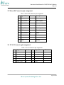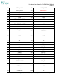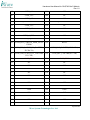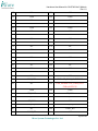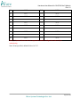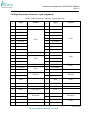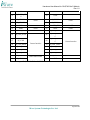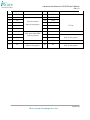
1
Hardware User Manual for G8 Q7M i.Mx51 Module Rev 1.0 Hardware User Manual for G8 Q7M i.Mx51 Module iW-PRDUQ-UM-01-R1.0 REL1.0 th 11 Nov, 2011 Page 1 of 34 iWave Systems Technologies Pvt. Ltd. Hardware User Manual for G8 Q7M i.Mx51 Module Rev 1.0 Author’s Raghavendra C APPROVAL Name Mr. Immanuel Distribution Function Associate Director Organization iWave Systems Date Signature iWave Systems Technologies Pvt. Ltd. CONTACT INFO Name iWave Systems Technologies Pvt. Ltd. No. 7/B, 29th Main, BTM Layout 2nd Stage, Bangalore - 560 076. INDIA. Telephone +91-80-26786245, +91-80-26683700 e-mail [email protected] DOCUMENT IDENTIFICATION Project Name Document Name Document Home Release No Status Audience iW-RAINBOW-G8 Q7M User Manual iWave Server (file://server/prduq/svn/) REL 1.0 Initial Release Version Page 2 of 34 iWave Systems Technologies Pvt. Ltd. Hardware User Manual for G8 Q7M i.Mx51 Module Rev 1.0 DOCUMENT REVISION HISTORY Revision 1.0 11 th Date Nov 2011 Change Description Initial Draft Release Updated By Raghavendra Reviewed By Immanuel PROPRIETARY NOTICE: This document contains proprietary material for the sole use of the intended recipient(s). Do not read this document further if you are not the intended recipient. Any review, use, distribution or disclosure by others is strictly prohibited. If you are not the intended recipient (or authorized to receive for the recipient), you are hereby notified that any disclosure, copy or distribution or use of any of the information contained within this document is STRICTLY PROHIBITED. Thank you. “iWave Systems Tech. Pvt. Ltd.”s Page 3 of 34 iWave Systems Technologies Pvt. Ltd. Hardware User Manual for G8 Q7M i.Mx51 Module Rev 1.0 Table of Contents 1. INTRODUCTION..................................................................................................................... 6 1.1 PURPOSE ................................................................................................................................. 6 1.2 SCOPE ..................................................................................................................................... 6 1.3 ACRONYMS AND ABBREVIATIONS .......................................................................................... 6 2. HARDWARE DETAILS .......................................................................................................... 7 2.1 BOARD CONFIGURATIONS AND DEFAULT FEATURES.............................................................. 7 2.2 POWER RATING ...................................................................................................................... 7 2.3 GUIDELINES TO INSERT THE PROCESSOR BOARD INTO CARRIER BOARD ................................. 8 3. I.MX51 Q7 MODULE CONNECTOR PIN ASSIGNMENTS ............................................. 9 3.1 I.MX51 Q7 MODULE TOP ....................................................................................................... 9 3.2 I.MX51 Q7 MODULE BOTTOM .............................................................................................. 10 3.3 MICRO SD CONNECTOR PIN ASSIGNMENT ............................................................................ 11 3.4 JTAG CONNECTOR PIN ASSIGNMENT ................................................................................... 11 3.5 230PIN EDGE CONNECTOR PIN ASSIGNMENT ........................................................................ 12 3.6 80PIN EXPANSION CONNECTOR-1 PIN ASSIGNMENT.............................................................. 17 3.7 80PIN EXPANSION CONNECTOR-2 PIN ASSIGNMENT.............................................................. 19 4. FLASH PROGRAMMING USING ATK ............................................................................ 21 4.1 INSTRUCTIONS TO INSTALL ADVANCED TOOLKIT ................................................................. 21 4.2 PROGRAMMING I.MX51 BOARD USING ADVANCED TOOL KIT ............................................. 22 4.3 FLASH PROGRAMMING THE BOOT CODE .............................................................................. 23 FLASH PROGRAMMING THE WINCE IMAGE................................................................................ 24 5. HYPER TERMINAL SET UP & BOOT OS FROM NAND FLASH ............................... 25 5.1 HYPER TERMINAL SET UP ..................................................................................................... 25 5.2 DEFAULT CONFIGURATION SETUP ........................................................................................ 29 5.3 POWER ON AND LAUNCH WINCE FROM NAND FLASH ...................................................... 30 6. REFERENCE DOCUMENTS/LINKS ................................................................................. 33 7. TECHNICAL SUPPORT....................................................................................................... 34 Page 4 of 34 iWave Systems Technologies Pvt. Ltd. Hardware User Manual for G8 Q7M i.Mx51 Module Rev 1.0 List of Figures Figure 1: Q7 Module Insertion procedure ...................................................................................... 8 Figure 2: i.Mx51 Q7 Module Connector detail Top ....................................................................... 9 Figure 3: i.Mx51 Q7 Module Connector detail Bottom ............................................................... 10 Figure 4: ATK Window ................................................................................................................ 21 Figure 5: Switch Position for Boot Strap Mode ........................................................................... 22 Figure 6: HyperTerminal settings-1 .............................................................................................. 25 Figure 7: HyperTerminal settings-2 .............................................................................................. 26 Figure 8: Enable Echo typed characters........................................................................................ 27 Figure 9: UART Console Window ............................................................................................... 28 Figure 10: Diagnostic Main Menu ................................................................................................ 29 Figure 11: Board Configuration Menu ......................................................................................... 30 Figure 12: Diagnostic Main Menu ................................................................................................ 31 Figure 13: Launch WINCE ........................................................................................................... 31 Figure 14: WinCE Desktop ........................................................................................................... 32 List of Tables Table 1: Acronyms and Abbreviations ........................................................................................... 6 Table 2: Board Configurations........................................................................................................ 7 Table 3: Micro SD connector pin assignment............................................................................... 11 Table 4: JTAG Connector pin assignment .................................................................................... 11 Table 5: 230pin Edge Connector pin assignment ......................................................................... 12 Table 6: 80pin Expansion Connector-1 pin assignments .............................................................. 17 Table 7: 80pin Expansion Connector-2 pin assignment ............................................................... 19 Page 5 of 34 iWave Systems Technologies Pvt. Ltd. Hardware User Manual for G8 Q7M i.Mx51 Module Rev 1.0 1. Introduction 1.1 Purpose The purpose of this document is to explain the procedure about the user interface, Power ON procedure for i.Mx51 Q7 Module. 1.2 Scope This document describes the Hardware details, ATK flash programming and setting up Serial communication with PC/Laptop & ATK Flash programming for i.Mx51 Q7 Module. 1.3 Acronyms and Abbreviations Table 1: Acronyms and Abbreviations Acronyms ATK CAN LCD DDR FAQ HT MMC PC RS232 SATA SD UART USB VGA Description. Advanced Tool Kit Controller Area Network Liquid Crystal Display Double Data Rate Frequently Asked Question Hyper Terminal Multi Media Card Personal computer Recommended Standard 232 Serial Advanced Technology Attachment Secure Digital Universal Asynchronous Receiver Transmitter Universal Serial Bus Video graphic Array Page 6 of 34 iWave Systems Technologies Pvt. Ltd. Hardware User Manual for G8 Q7M i.Mx51 Module Rev 1.0 2. Hardware Details 2.1 Board Configurations and Default Features Table 2: Board Configurations Board Configuration Feature Default Configuration Optional Configurations DDR2 128MB 512MB NANDF(1) 128MB 2GB Micro SD slot YES YES USB Host x4 YES YES USB OTG x1 YES YES Ethernet PHY YES YES LVDS transmitter (RGB to LVDS) YES YES 80Pin Expansion Conn1 YES YES 80Pin Expansion Conn 2 YES YES CAN Controller (SPI interface) NO YES PATA to SATA bridge(1) NO YES SPI NOR Boot Flash NO YES Note (1): Both NANDF & SATA interfaces are not accessible simultaneously. Both interfaces are sharing same IO lines from CPU 2.2 Power Rating Input supply to the Q7 module form MXM connector should meet below power & tolerance requirement. Input Voltage: 5V ± 5% Input Current: 1A Page 7 of 34 iWave Systems Technologies Pvt. Ltd. Hardware User Manual for G8 Q7M i.Mx51 Module Rev 1.0 2.3 Guidelines to insert the Processor board into Carrier board Make sure that the carrier board is completely powered off. Insert the Q7 module in to the MXM connector at an angle of 45° as shown in Figure 3. Check the Notch position of Q7 module is proper while inserting. Insert the Q7 module as shown in below. Once the Q7 module is inserted to the MXM connector properly, press the board vertically down as shown below, such that the board is fixed firmly into the expansion connectors. Figure 1: Q7 Module Insertion procedure Page 8 of 34 iWave Systems Technologies Pvt. Ltd. Hardware User Manual for G8 Q7M i.Mx51 Module Rev 1.0 3. i.Mx51 Q7 Module Connector Pin Assignments 3.1 i.Mx51 Q7 Module Top Figure 2: i.Mx51 Q7 Module Connector detail Top Above Figure Shows the CPU module connector reference numbers on top side. Following are the list of Connectors on Top side Micro SD slot (J1) JTAG Connector (J2) Stand alone Power connector (P1) Power Jack(J3) 230pin Edge connector Top (U22) BOOT Switch (S1) Page 9 of 34 iWave Systems Technologies Pvt. Ltd. Hardware User Manual for G8 Q7M i.Mx51 Module Rev 1.0 3.2 i.Mx51 Q7 Module Bottom Figure 3: i.Mx51 Q7 Module Connector detail Bottom Above Figure Shows the CPU module connector reference numbers on bottom side. Following are the list of Connectors on Bottom side. 80pin Expansion connector 1 (U23) 80pin Expansion connector 2 (U24) 230pin Edge connector Bottom (U22) Page 10 of 34 iWave Systems Technologies Pvt. Ltd. Hardware User Manual for G8 Q7M i.Mx51 Module Rev 1.0 3.3 Micro SD Connector pin assignment Table 3: Micro SD connector pin assignment Pin Signal Name Direction Description 1 SD1_DATA2 IO Data2 Signal 2 SD1_DATA3 IO Data3 Signal 3 SD1_CMD 4 VSD Power 3.15V power 5 SD1_CLK Output Clock signal 6 VSS1 7 SD1_DATA0 IO Data0 8 SD1_DATA1 IO Data1 9 SD1_CD Input Card Detect 10 VSS1 Command Signal Ground Ground 3.4 JTAG Connector pin assignment Table 4: JTAG Connector pin assignment Pin Signal Name 1 1V8_DDR 3 JTAG_TDI 5 GND 7 JTAG_DE_B 9 JTAG_TDO Direction Pin Signal Name Direction 2 JTAG_TRST_B IO 4 JTAG_TMS IO 6 VCC_3V3 IO IO 8 JTAG_TCK IO IO 10 GND IO Page 11 of 34 iWave Systems Technologies Pvt. Ltd. Hardware User Manual for G8 Q7M i.Mx51 Module Rev 1.0 3.5 230pin Edge Connector pin assignment Table 5: 230pin Edge Connector pin assignment Pin Signal (bottom) Pin Signal (top) 1 GND 2 GND 3 NC 4 NC 5 NC 6 NC 7 LINK100# 8 NC 9 MDI1-/10,100Mbps Tx/Rx- 10 MDI0-/10,100Mbps Tx/Rx- 11 MDI1+/10,100Mbps Tx/Rx+ 12 MDI0+/10,100Mbps Tx/Rx+ 13 LINK# 14 ACT# 15 CTREF 16 NC 17 WAKE#/GPIO 18 SUS_S3#/GPIO 19 SUS_STAT#/GPIO 20 PWRBTN# 21 NC 22 NC 23 GND 24 GND 25 GND 26 PWRGIN/GPIO 5V CMOS INPUT 27 NC 28 RSTBN#/ INPUT 29 SATA0_TX+ * 30 NC 31 SATA0_TX- * 32 NC 33 SATA_ACT#/OC_OUTPUT * 34 GND 35 SATA0_RX+ * 36 NC 37 SATA0_RX- * 38 NC 39 GND 40 GND 41 NC 42 SDIO_CLK# 43 SDIO_CD# 44 SDIO_LED 45 SDIO_CMD 46 SDIO_WP 47 SDIO_PWR/GPIO OUTPUT 48 SDIO_DAT1 Page 12 of 34 iWave Systems Technologies Pvt. Ltd. Hardware User Manual for G8 Q7M i.Mx51 Module Rev 1.0 49 SDIO_DAT0 50 SDIO_DAT3 51 SDIO_DAT2 52 SDIO_DAT5 * 53 SDIO_DAT4 * 54 SDIO_DAT7 * 55 SDIO_DAT6 * 56 RSVD 57 GND 58 GND 59 HDA_SYNC (AC‟97) 60 NC 61 HDA_RST/GPIO OUTPUT 62 NC 63 HDA_BITCLK (AC‟97) 64 NC 65 HDA_SDI (AC‟97) 66 I2C_CLK 67 HAD_SDO (AC‟97) 68 I2C_DAT 69 NC 70 WDTRIG# 71 NC 72 WDOUT 73 GND 74 GND 75 NC 76 NC 77 NC 78 NC 79 NC 80 USB_4_5_OC# 81 NC 82 USB_P4- 83 NC 84 USB_P4+ 85 USB_2_3_OC# 86 USB_0_1_OC# 87 USB_P3- 88 USB_P2- 89 USB_P3+ 90 USB_P2+ 91 USB_CC 92 USB_ID 93 USB_P1-/OTG- 94 USB_P0- 95 USB_P1+/OTG+ 96 USB_P0+ 97 GND 98 GND 99 LVDS_A0+ 100 NC 101 LVDS_A0- 102 NC 103 LVDS_A1+ 104 NC Page 13 of 34 iWave Systems Technologies Pvt. Ltd. Hardware User Manual for G8 Q7M i.Mx51 Module Rev 1.0 105 LVDS_A1- 106 NC 107 LVDS_A2+ 108 NC 109 LVDS_A2- 110 NC 111 LVDS_PPEN/GPIO OUTPUT 112 LVDS_BLEN/GPIO OUTPUT 113 LVDS_A3+ 114 NC 115 LVDS_A3- 116 NC 117 GND 118 GND 119 LVDS_A_CLK+ 120 NC 121 LVDS_A_CLK- 122 NC 123 LVDS_BLT_CTRL/GP_PWM_OUT0/ PWM0 124 RSVD 125 LVDS_DID_DAT/GP_I2C_DAT/TBD( I2C DATA) 126 LVDS_BLC_DAT/TBD(I2C DATA) 127 LVDS_DID_CLK/GP_I2C_CLK/TBD( I2C CLK) 128 LVDS_BLC_CLK/TBD(I2C CLK) 129 CAN0_TX * 130 CAN0_RX * 131 NC 132 NC 133 NC 134 NC 135 GND 136 GND 137 NC 138 NC 139 NC 140 NC 141 GND 142 GND 143 NC 144 NC 145 NC 146 NC 147 GND 148 GND 149 NC 150 /NC 151 NC 152 NC 153 NC 154 NC 155 NC 156 NC Page 14 of 34 iWave Systems Technologies Pvt. Ltd. Hardware User Manual for G8 Q7M i.Mx51 Module Rev 1.0 157 NC 158 NC 159 GND 160 GND 161 NC 162 NC 163 NC 164 NC 165 GND 166 GND 167 NC 168 NC 169 NC 170 NC 171 NC 172 NC 173 NC 174 NC 175 NC 176 NC 177 NC 178 NC 179 NC 180 NC 181 NC 182 NC 183 GND 184 GND 185 NC 186 NC 187 NC 188 NC 189 NC 190 NC 191 NC 192 NC 193 VCC_RTC 194 SPKR / GP_PWM_OUT2/PWM1 195 NC 196 FAN_PWMOUT/GP_PWM_OUT1 /TBD (OUTPUT)* 197 GND 198 GND 199 SPI_MOSI 200 SPI_CS0# 201 SPI_MISO 202 SPI_CS1# 203 SPI_SCK 204 NC 205 VCC_5V_SB 206 VCC_5V_SB 207 NC 208 UART_RX 209 UART_TX 210 NC Page 15 of 34 iWave Systems Technologies Pvt. Ltd. Hardware User Manual for G8 Q7M i.Mx51 Module Rev 1.0 211 VCC 212 VCC 213 VCC 214 VCC 215 VCC 216 VCC 217 VCC 218 VCC 219 VCC 220 VCC 221 VCC 222 VCC 223 VCC 224 VCC 225 VCC 226 VCC 227 VCC 228 VCC 229 VCC 230 VCC Note (*): Optional feature and not supported in default configuration due to of pin multiplexing. Note: If not specified, default IO level is 3V3 Page 16 of 34 iWave Systems Technologies Pvt. Ltd. Hardware User Manual for G8 Q7M i.Mx51 Module Rev 1.0 3.6 80pin Expansion Connector-1 pin assignment Table 6: 80pin Expansion Connector-1 pin assignments Pin # signal Pin # signal 1 GND 2 B_GPIO0 3 B_GPIO1 4 B_GPIO2 5 B_GPIO3 6 B_GPIO4 7 B_GPIO5 8 B_GPIO6 9 B_GPIO7 10 B_GPIO8 11 B_GPIO9 12 B_GPIO10 13 B_GPIO11 14 B_GPIO12 15 B_GPIO13 16 B_GPIO14 17 B_GPIO15 18 B_GPIO16 19 PWM 20 B_GPIO20 21 B_GPIO21 22 B_GPIO22 23 B_GPIO23 24 B_GPIO24 25 B_GPIO25 26 B_GPIO26 27 GND 28 B_GPIO27 29 B_GPIO28 30 B_GPIO29 31 B_GPIO30 32 GND 33 AI_MCLK 34 AI_LRCK 35 AI_BCLK 36 AI_DATA 37 GND 38 GPIO GPIO 39 GND 40 B_LVDS_BLEN LVDS Backlight control 41 TS_INT# Touch screen interrupt 42 GND 43 GPIO GPIO Input 44 GND 45 AO_DATA 46 AO_BCLK 47 AO_LRCK 48 AO_MCLK 49 GND 50 B_UART1_TX 51 B_UART1_RT 52 B_UART1_RX Instants GPIO PWM GPIO GPIO SSI Input SSI Output UART Instants GPIO GPIO GPIO SSI Input SSI Output UART Page 17 of 34 iWave Systems Technologies Pvt. Ltd. Hardware User Manual for G8 Q7M i.Mx51 Module Rev 1.0 S 53 B_UART1_CT S 55 B_GPIO31 57 B_GPIO33 59 GND 61 GPIO 63 UART3_RXD 65 67 54 GND 56 B_GPIO32 58 B_GPIO34 60 UART3_TXD UART GPIO 62 GPIO GPIO UART 64 B_CSI1_MCLK B_CSI1_PCLK 66 B_CSI1_HSYN C B_VCLK 68 B_CSI1_VSYN C 69 B_CSI1_DAT0 71 GPIO Camera Interface 70 B_CSI1_DAT1 B_CSI1_DAT2 72 B_CSI1_DAT3 73 B_CSI1_DAT4 74 B_CSI1_DAT6 75 B_CSI1_DAT7 76 B_CSI1_DAT5 77 B_GPIO17 78 B_GPIO18 79 B_GPIO19 80 GND GPIO Bidirectional GPIO Camera Interface GPIO Bidirectional Note: If not specified, default IO level is 3V3 Page 18 of 34 iWave Systems Technologies Pvt. Ltd. Hardware User Manual for G8 Q7M i.Mx51 Module Rev 1.0 3.7 80pin Expansion Connector-2 pin assignment Table 7: 80pin Expansion Connector-2 pin assignment Pin# signal 1 TSX2 3 TSY2 5 Instants Pin# signal 2 TSX1 4 TSY1 GND 6 GND 7 KP_ROW0 8 KP_ROW1 9 KP_ROW2 Keypad (4x4) 10 KP_ROW3 Keypad (4x4) 11 KP_COL0 (2V775 IO Level) 12 KP_COL1 (2V775 IO Level) 13 KP_COL2 14 KP_COL3 15 GND 16 GND 17 EIM_DA1 18 EIM_DA0 19 EIM_DA3 20 EIM_DA2 21 EIM_DA5 22 EIM_DA4 23 EIM_DA7 24 EIM_DA6 25 EIM_DA9 26 EIM_DA8 28 EIM_DA10 EIM Interface 30 EIM_DA12 (1V8 IO Level) Touch interface EIM Interface 27 EIM_DA11 29 EIM_DA13 31 EIM_DA15 32 EIM_DA14 33 GND 34 GND 35 EIM_RW 36 EIM_CS0 37 EIM_BCLK 38 EIM_CRE 39 EIM_EB1 40 EIM_WAIT 41 AUD6_RXD 42 EIM_EB0 43 AUD6_TXFS 44 AUD6_TXD 45 AUD6_TXC 46 GND 47 GND 48 CSI2_D13 49 CSI2_D12 50 CSI2_D15 51 CSI2_D14 Camera2 interface 52 CSI2_D17 53 CSI2_D16 (2V775 IO Level) 54 CSI2_D18 55 CSI2_D19 56 CSI2_HSYNC (1V8 IO Level) Audio Interface (1V8 IO Level) Instants Touch interface Audio Interface(1V8 IO Level) Camera2 interface (2V775 IO Level) Page 19 of 34 iWave Systems Technologies Pvt. Ltd. Hardware User Manual for G8 Q7M i.Mx51 Module Rev 1.0 57 CSI2_VSYNC 58 CSI2_PIXCLK 59 GND 60 GND 61 NC 62 TV_OUT_RED 63 NC 64 GND 65 NC 66 TV_OUT_GRN 67 NC 68 GND 69 NC 70 TV_OUT_BLU 71 ADIN7 72 GND 73 ADIN6 74 TP Leave no connect 75 ADIN5 76 TP Only for test purpose 77 GND 78 GND 79 NC 80 NC Leave no connect Only for test purpose ADC inputs from PMIC Leave no connect Leave no connect Only for test purpose TV out Leave no connect Only for test purpose Page 20 of 34 iWave Systems Technologies Pvt. Ltd. Hardware User Manual for G8 Q7M i.Mx51 Module Rev 1.0 4. Flash Programming using ATK 4.1 Instructions to install Advanced Toolkit 1. Install the Advanced Toolkit by double clicking the file FSL_ATK_TOOL_WINS_STD_INSTALL_1_67.exe 2. After installing setup, double click on Advanced Tool Kit V1.67 to get the window Figure 4: ATK Window Page 21 of 34 iWave Systems Technologies Pvt. Ltd. Hardware User Manual for G8 Q7M i.Mx51 Module Rev 1.0 4.2 Programming i.MX51 board using Advanced Tool Kit 1. Connect USB Cable between USB OTG (mini AB, J26) port of Q7 carrier card and PC. 2. Set the Bootstrap mode in the Processor board as mentioned in picture below (DIP switch to ON position for bootstrap). Don‟t change the switch setting while power is ON. 3. After changing the switch position, Power On the system. 4. 5. 6. 7. 8. Figure 5: Switch Position for Boot Strap Mode Run the Open Advanced Toolkit application by double clicking the “Advanced Tool Kit V1.67” located in Desktop. In Device Setting select the i.MX CPU as iMX51 TO2. In Device Initial File select the Custom Initial file and Browse the Custom DDR initialization file “ddr_0to15.txt”. In Host Setting, select Communication channel as “USB”. Click Next to Continue 9. Select Flash Tool and Click Go button. Page 22 of 34 iWave Systems Technologies Pvt. Ltd. Hardware User Manual for G8 Q7M i.Mx51 Module Rev 1.0 4.3 Flash Programming the Boot Code 1. In the next screen select below things. 2. Select Flash model as Custom model. 3. Click Browse button (under Flash model) and Select the given Binary File (“mx51to2_nand.bin”) 4. In Operation type Select Program. 5. In Operation settings, type Address as “0”. 6. Click Browse button (Under image) and select the image file (“imx51_diag.bin”). 7. Click Program button. Page 23 of 34 iWave Systems Technologies Pvt. Ltd. Hardware User Manual for G8 Q7M i.Mx51 Module Rev 1.0 8. Next NK.bin has to be programmed. Flash Programming the WinCE Image 1. In the next screen select below things. 2. Select Flash model as Custom model. 3. Click Browse button (under Flash model) and Select the given Binary File (“mx51to2_nand.bin”). 4. In Operation type Select Program. 5. In Operation settings, type Address as “100000”. 6. Click Browse button (Under image) and select the image file (“NK.bin”). 7. Click Program button. 8. After successful programming, switch off the power supply & put the DIP switch in Boot mode. Page 24 of 34 iWave Systems Technologies Pvt. Ltd. Hardware User Manual for G8 Q7M i.Mx51 Module Rev 1.0 5. Hyper Terminal Set up & boot OS from NAND Flash 5.1 Hyper Terminal Set up 1. 2. 3. 4. Insert one end of the serial cable to PC/Laptop COM port (DB9 Male Connector.) Connect the other end of the serial cable to serial connector of the Board. Open the HyperTerminal on the PC/Laptop as mentioned below Go to Start -> Programs -> Accessories -> Communication -> HyperTerminal on the host PC/Laptop. 5. In hyperterminal,Go to Files ->Properties 6. Select COM1 or COM2 port depending on which port you have connected the serial cable as shown below. Figure 6: HyperTerminal settings-1 Page 25 of 34 iWave Systems Technologies Pvt. Ltd. Hardware User Manual for G8 Q7M i.Mx51 Module Rev 1.0 7. Now Click Configure button and do Port Settings as below.. Bits per Second (Baud Rate) :115200 Data bits :8 Parity :None Stop Bits :1 Flow Control :None Figure 7: HyperTerminal settings-2 8. Go to File -> Properties -> Settings ->ASCII Setup. 9. Now Select „Echo typed characters locally‟ has to be enabled as shown below 10. Go to Call -> Call to connect. Page 26 of 34 iWave Systems Technologies Pvt. Ltd. Hardware User Manual for G8 Q7M i.Mx51 Module Rev 1.0 11. If you want to disconnect, Go to Call -> Disconnect. Figure 8: Enable Echo typed characters 12. The UART console messages will appear on the HT as shown below. Page 27 of 34 iWave Systems Technologies Pvt. Ltd. Hardware User Manual for G8 Q7M i.Mx51 Module Rev 1.0 Figure 9: UART Console Window Page 28 of 34 iWave Systems Technologies Pvt. Ltd. Hardware User Manual for G8 Q7M i.Mx51 Module Rev 1.0 5.2Default Configuration Setup Power the Board, the below diagnostics Menu will appear in the hyper terminal. Figure 10: Diagnostic Main Menu Press “E” for Board Configuration and enter the password as “aaabacad”. Page 29 of 34 iWave Systems Technologies Pvt. Ltd. Hardware User Manual for G8 Q7M i.Mx51 Module Rev 1.0 Figure 11: Board Configuration Menu In Board Configuration menu, again press “E” for Programming the Default Configuration. After Programming the Default Configuration reboot the board. 5.3 Power ON and Launch WinCE from NAND Flash Power on the system. Diagnostic Main Menu will appear in Hyper Terminal. Page 30 of 34 iWave Systems Technologies Pvt. Ltd. Hardware User Manual for G8 Q7M i.Mx51 Module Rev 1.0 Figure 12: Diagnostic Main Menu Select “I” Option from Menu to load WINCE, the below menu will appear. Figure 13: Launch WINCE Page 31 of 34 iWave Systems Technologies Pvt. Ltd. Hardware User Manual for G8 Q7M i.Mx51 Module Rev 1.0 Select “B” for Load WinCE from NAND flash. Wait for 1 min for WinCE 6.0 boots up, WinCE Desktop screen will be displayed in the LCD screen as shown below. Figure 14: WinCE Desktop Page 32 of 34 iWave Systems Technologies Pvt. Ltd. Hardware User Manual for G8 Q7M i.Mx51 Module Rev 1.0 6. Reference Documents/Links Q7 specification: http://www.qseven-standard.org/fileadmin/spec/Qseven-Spec_1.20.pdf Carrier card design guide: http://www.qseven-standard.org/fileadmin/spec/Qseven-DG_10_Release_Candidate.pdf Carrier card reference schematic: http://www.qseven-standard.org/fileadmin/spec/reference_carrier_schematics_sp31e900001.pdf Brochure & high level Block diagrams for iWave G8 Q7M i.Mx51 module: http://www.iwavesystems.com/i.MX51Q7SOM.htm Brochure & high level Block diagrams for iWave G7D Generic Q7 Carrier Card: http://www.iwavesystems.com/iW-RainboW-G7D.htm ATK User Guide: ATK User's Guide Standard Version.pdf Page 33 of 34 iWave Systems Technologies Pvt. Ltd. Hardware User Manual for G8 Q7M i.Mx51 Module Rev 1.0 7. Technical Support iWave Systems Technologies Pvt. Ltd. # 7/B, 29th Main, BTM Layout 2nd Stage, Bengaluru – 560 076 Phone : +91-80-26683700, 26786245 Fax : +91-80-26685200 Email : [email protected] Web site: http://www.iwavesystems.com Page 34 of 34 iWave Systems Technologies Pvt. Ltd.