1
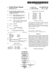
US 20110318032Al
(19) United States
(12) Patent Application Publication (10) Pub. N0.: US 2011/0318032 A1
MURAYAMA et al.
(54)
(43) Pub. Date:
IMAGE FORMING APPARATUS
(75) Inventors:
(52)
Dec. 29, 2011
US. Cl. ............................ .. 399/49; 399/81; 399/301
Kentaro MURAYAMA,
Kasugai-shi (JP); Osamu
TAKAHASHI, Nagoya-shi (JP)
_
(73) Ass1gnee:
(57)
BROTHER KOGYO
KABUSHIKI KAISHA,
Nagoya-511i (JP)
ABSTRACT
An image forming apparatus is provided. The image forming
apparatus includes: a manual acquiring unit Which is con?g
_
ured to receive a user input to acquire a correction value; an
(21) Appl' NO"
13/072’823
image forming unit Which is con?gured to form an image
(22)
M311 28, 2011
While adjusting at least one of positional deviation and den
(30)
Filed?
Foreign Application Priority Data
sity deviation of the image based on the correction value; and
Jun. 28, 2010
(JP) ............................... .. 2010-146582
P bl,
_
Cl
_?
_
u lcatlon assl canon
( 51 ) Int. Cl.
G03G 15/00
G03G 15/01
(200601)
(200601)
a changing unit Which is con?gured to execute at least one of
a ?rst Changing Process Of Changing a Permissible range Of a
correction value for positional deviation according to a status
of a factor causing a change in a position of an image, and a
second changing P rocess of changing a P ermissible rang e of
a correction value for density deviation according to a status
of a factor causing a change in a density of an image.
(MANUALACQUIRING PROCESS)
READ OUT CORRECTION VALUES ~ $101
ACQUIRE DATA 0F FACTOR
~ 8102
CAUSING CHANGE
I CALCULATE PERMISSIBLE RANGE
~ $103
ADJUST PERMISSIBLE RANGE
*- 3104
PRINT PATTERN IMAGE
~ $105
,
>
I=
S1 06
INSTRUCTION
TO COMPLETE INPUT
'
?
YES
S111
S107 w
ACQUIRE INPUT VALUE
'
CANCEL INSTRUCTION
I '?
I
8108 _,_
I
YES
UPDATE MANUAL -
CORRECTION VALUE
I
I
0
END
.
Patent Application Publication
Dec. 29, 2011 Sheet 1 0f 9
US 2011/0318032 A1
FIG. 1
100
./
MFP
_
30
/
CONTROL UNIT
35
/
31 A
cPu
<——>
32 ,
ROM
"
'
<
IMAGE FORMING UNIT ~10
33-’
RAM
‘w’
<
> IMAGE READING UNIT ‘~20
ASIC
34’
NVRAM
37 v"
FAX HF
‘_’
36?’- NETWORK l/F 4-’
<—-A
OPERATION PANEL ~40
Patent Application Publication
Dec. 29, 2011 Sheet 2 0f 9
US 2011/0318032 A1
40
8 1U)
7 \50Y
'
50M
50c
5°
50K,
71
I
Patent Application Publication
3
FIG._
Dec. 29, 2011 Sheet 3 0f 9
US 2011/0318032 A1
Patent Application Publication
Dec. 29, 2011 Sheet 4 0f 9
mwGI
2.:|NT
my
US 2011/0318032 A1
Patent Application Publication
Dec. 29, 2011 Sheet 5 0f 9
US 2011/0318032 A1
FIG. 5
(MANUALACQUIRING PROCESS)
II
READ OUT CORRECTION VALUES ~ $101
II
ACQUIRE DATA 0F FACTOR
~ $102
CAUSING CHANGE
-II
I CALCULATE PERMISSIBLE RANGE
~ S103
II
ADJUST PERMISSIBLE RANGE
~ $104
I
PRINT PATTERN IMAGE
$106
Y
~ $105
>
I
INSTRUCTION
To COMPLI’ETE INPUT
YES
S111
8107 w ACQUIRE INPUT VALUE
CANCEL INSTRUCTION
I ?
II
S108 _,_
UPDATE MANUAL -
CORRECTION VALUE
END
YES
Patent Application Publication
Dec. 29, 2011 Sheet 6 0f 9
US 2011/0318032 A1
FIG. 6
341. \
_
THE NUMBER
'
ASSUMED EXPANSION
OF PRINTED PAGES
1 .-1000
AMOUNT
O
1001 -2000
2
2001 -3000
4
3001-4000
6
4 0 0 1 -
8
FIG. 7
342 '\
TEMPERATURE
DIFFERENCE
o - 1 O
ASSUMED EXPANSION
AMOUNT
O A
1 1 ¢ 1 5
1
1 6 - 2 O
.2
2 1 - 2 5
a
2 6
4
-
1
Patent Application Publication
8
FIG.
Dec. 29, 2011 Sheet 7 0f 9
86K
i2
m
l
-4
-5
-7
-8
-9
-11-10
.
US 2011/0318032 A1
Patent Application Publication
Dec. 29, 2011 Sheet 8 0f 9
US 2011/0318032 A1
FIG. 9
(AUTOMATIC ACQUIRING PROCESS)
T
READ OUT CORRECTION VALUES
--~-- $201
V
FORM REGISTRATION PATTERN
- S202
DETECT REGISTRATION PATTERN
- $203 .
CALCULATE AMOUNT OF DEVIATION '- S204
S205
AMOUNT
OF DEVIATION IS WITHIN
PREDETERMINED
RANGE?
YES
szoe
YES
‘_, UPDATE AUTOMATIC
CORRECTIONVALUE
ADJUSTMENT
COLOR THAT HAS NOT
YET DETERMINED
REMATNS?
NOTIFYERROR
__
S211
Patent Application Publication
Dec. 29, 2011 Sheet 9 0f 9
US 2011/0318032 A1
FIG. 10
' (PRINTING PROCESS)
i
READ OUT CORRECTION VALUES -~--‘ 8301
i
ACQUIRE IMAGE DATA
FORM IMAGE
@D
_
.
}» S302
8303
US 2011/0318032 A1
IMAGE FORMING APPARATUS
CROSS-REFERENCE TO RELATED
APPLICATION
[0001] This application claims priority from Japanese
Patent Application No. 2010-146582, ?led on Jun. 28, 2010,
the entire subject matter of Which is incorporated herein by
reference.
TECHNICAL FIELD
Dec. 29, 2011
from the folloWing description of illustrative embodiments of
the present invention taken in conjunction With the attached
draWings, in Which:
[0010] FIG. 1 is a block diagram shoWing an electrical
con?guration of an MFP;
[0011] FIG. 2 shoWs a schematic con?guration of an image
forming unit of the MFP shoWn in FIG. 1;
[0012]
[0013]
pattern image;
[0014]
[0002] Aspects of the present invention relate to an image
forming apparatus that adjusts a position or density of an
image based on a correction value input by a user.
BACKGROUND
FIG. 3 shoWs an arrangement of mark sensors;
FIGS. 4A and 4B shoW a printing example of a
FIG. 5 is a How chart shoWing a sequence of a
manual acquiring process;
[0015] FIG. 6 shoWs a printed page number limiting table;
[0016] FIG. 7 shoWs a temperature limiting table;
[0017] FIG. 8 shoWs a printing example of a pattern image
[0003] An image forming apparatus performs an image
on Which a current correction value is re?ected;
[0018] FIG. 9 is a How chart shoWing a sequence of an
adjustment so that a position or density of an image is not
automatic acquiring process; and
deviated. For example, an image forming apparatus has been
[0019]
knoWn Which receives a correction value input by a user
printing process.
FIG. 10 is a How chart shoWing a sequence of a
through an operation panel or a printer driver and performs an
image adjustment of adjusting positional deviation or density
DETAILED DESCRIPTION
deviation based on the correction value When forming an
[0020]
image.
[0004] JP-A-2005-234454 describes a technique of acquir
ing the correction value by the user input, Which includes
printing a pattern image for positional deviation correction on
a sheet and alloWs a user to determine and input a correction
value based on a printing result thereof.
[0005]
HoWever, the above image forming apparatus has a
Hereinafter, an image forming apparatus and an
image forming system according to illustrative embodiments
Will be described With reference to the accompanying draW
ings. In the illustrative embodiments, the present invention is
applied to a multi function peripheral (MFP) having a color
printing function.
[0021] [Con?guration of MFP]
folloWing problem. That is, in the image forming apparatus
[0022]
that acquires the correction value by the user input, When the
embodiment includes a control unit 30 having a CPU 31, a
As shoWn in FIG. 1, an MFP 100 of this illustrative
input correction value is considerably inappropriate, a quality
ROM 32, a RAM 33, an NVRAM (non-volatile RAM) 34, an
of an image may be remarkably deteriorated.
ASIC 35, a netWork interface 36 and a FAX interface 37. In
SUMMARY
addition, the control unit 30 is electrically connected to an
image forming unit 10 that forms an image on a sheet, an
image reading unit 20 that reads out an image of a sheet and
[0006] Accordingly, it is an aspect of the present invention
to provide an image forming apparatus that can suppress
performs an image adjustment based on a correction value
receives an input operation by a user.
input by a user and can suppress a quality of an image from
various functions such as an image reading function, an
being deteriorated.
[0007]
According to an illustrative embodiment of the
present invention, there is provided an image forming appa
ratus comprising: a manual acquiring unit Which is con?g
ured to receive a user input to acquire a correction value; an
image forming unit Which is con?gured to form an image
While adjusting at least one of positional deviation and den
sity deviation of the image based on the correction value; and
a changing unit Which is con?gured to execute at least one of
a ?rst changing process of changing a permissible range of a
correction value for positional deviation according to a status
of a factor causing a change in a position of an image, and a
second changing process of changing a permissible range of
a correction value for density deviation according to a status
of a factor causing a change in a density of an image.
[0008] According to the above con?guration, there is pro
vided an image forming apparatus that performs an image
adjustment based on a correction value input by a user and can
suppress a quality of an image from being deteriorated.
BRIEF DESCRIPTION OF THE DRAWINGS
[0009] The above and other aspects of the present invention
Will become more apparent and more readily appreciated
an operation panel 40 that displays an operation situation and
[0023]
The CPU 31 executes operations for implementing
image forming function, a FAX data transmission/reception
function and an image adjustment function (described later),
and functions as a center of control. The ROM 32 stores
therein various control programs for controlling the MFP
100, various settings, initial values and the like. The RAM 33
is used as a Work area from Which the various control pro
grams are read out or a storage area that temporarily stores
image data. The NVRAM 34 is a non-volatile storage device
and is used as a storage area that preserves various settings,
image data and the like.
[0024] Based on the control programs read out from the
ROM 32 or signals transmitted from various sensors, the CPU
31 controls the respective constitutional elements of the MFP
100 (for example, a turn-on timing of an exposure device
con?guring the image forming unit 10, driving motors of
various rollers con?guring a conveyance path of a sheet and a
moving motor of an image sensor unit con?guring the image
reading unit 20) through the ASIC 35 While storing results of
the processing in the RAM 33 or NVRAM 34.
[0025] The netWork interface 36 is connected to a netWork
and enables connection With the other information processing
apparatuses. The FAX interface 37 is connected to a tele
phone line and enables connection With a FAX apparatus of
US 2011/0318032 Al
Dec. 29, 2011
the other party. The MFP 100 performs data communication
With an external apparatus through the netWork interface 36
sheet on Which the toner images are transferred is conveyed to
the ?xing device 8 and is then heat-?xed on the sheet. Then,
or FAX interface 37.
toner image by an electro-photographic method and transfers
the sheet after the ?xing is discharged to the sheet discharge
tray 92.
[0034] The mark sensor 61 is provided doWnstream from
the process units 50Y, 50M, 50C, 50K and upstream from the
?xing device 8 With respect to the conveyance direction of the
sheet and detects a pattern for image adjustment formed on
the toner image on a sheet, a ?xing device 8 that ?xes un?xed
toner on the sheet, a sheet feeding tray 91 that accommodates
the conveyance belt 7.
[0035] Speci?cally, as shoWn in FIG. 3, the mark sensor 61
sheets therein before the image transfer and a sheet discharge
tray 92 Which receives sheets thereon after the image transfer.
includes tWo sensors, i.e., a sensor 61R that is arranged at a
right side of a Width direction of the conveyance belt 7 and a
sensor 61L that is arranged at a left side thereof. Each of the
sensors 61R, 61L is a re?ection-type optical sensor having a
[0026] [Con?guration of Image Forming Unit]
[0027]
Next, a con?guration of the image forming unit 10
of the MFP 100 Will be described With reference to FIG. 2.
The image forming unit 10 has a process unit 50 that forms a
The image reading unit 20 is arranged above the image form
ing unit 10.
[0028] The image forming unit 10 has an exposure device
53 that illuminates light to the respective process units 50Y,
50M, 50C, 50K, a conveyance belt 7 that conveys a sheet to
transfer positions of the respective process units 50Y, 50M,
pair of a light emitting element 62 (for example, LED) and a
light receiving element 63 (for example, photo transistor).
The mark sensor 61 illuminates light to a surface (dotted
ranges E in FIG. 3) of the conveyance belt 7 in an oblique
50C, 50K and a mark sensor 61 that detects a pattern image
formed on the conveyance belt 7.
direction by the light emitting elements 62 and receives the
[0029] In addition, the image forming unit 10 is provided
mark sensor can detect a mark 66 for image adjustment (mark
66 of FIG. 3 is an example of a mark for positional deviation
correction) by a difference betWeen an amount of re?ection
therein With a conveyance path 1 1 (one dotted and dashed line
in FIG. 2) having a substantial S shape so that the sheet
accommodated in the sheet feeding tray 91 positioned at a
bottom passes through a feeder roller 71, registration rollers
72, the process unit 50 and the ?xing device 8 and is then
light by the light receiving elements 63, respectively. The
light received When the mark for image adjustment passes and
an amount of re?ection light received that is directly received
from the conveyance belt 7.
guided to the sheet discharge tray 92 through sheet discharge
[0036] [Image Adjustment in MFP]
rollers 76.
[0030] The process unit 50 can form a color image and
[0037] Next, the image adjustment in the MFP 100 Will be
described. In the MFP 100, regarding the image adjustment, a
positional deviation correction that adjusts positions of
includes the process units corresponding to respective colors
50C, 50K are arranged at a predetermined interval in a con
images of the respective colors and a density deviation cor
rection that adjusts densities of the respective colors are per
formed. Both image adjustments include an acquiring pro
cess of acquiring amounts of deviation of adjustment colors
from a reference color and acquiring correction values speci
?ed by the amounts of deviation and a correcting process of
correcting an image based on the correction values. Herein
veyance direction of the sheet.
[0031] In the process unit 50, a surface of a photosensitive
to the positional deviation correction.
of yelloW (Y), magenta (M), cyan (C) and black (K) in par
allel. Speci?cally, the process unit 50 has the process unit 50Y
that forms an image of a Y color, the process unit 50M that
forms an image of an M color, the process unit 50C that forms
an image of a C color and the process unit 50K that forms an
image of a K color. The respective process units 50Y, 50M,
member is uniformly charged by a charging device. Then, the
photosensitive member is exposed by the light from the expo
sure device 53 and an electrostatic latent image correspond
ing to an image formed on a sheet is thus formed on the
photosensitive member. Then, toner is supplied to the photo
sensitive member through a developing device. Thereby, the
electrostatic latent image on the photosensitive member
becomes a visible image as a toner image.
[0032] The conveyance belt 7 is an endless belt member
that is Wound around the conveyance rollers 73, 74 and is
made of a resin material such as polycarbonate and the like.
The conveyance belt 7 is rotated in a counterclockwise direc
tion as the conveyance roller 74 is rotated. Thereby, the sheet
put on the conveyance belt is conveyed from the registration
rollers 72 toWard the ?xing device 8.
[0033]
The image forming unit 10 picks up the sheets
accommodated in the sheet feeding tray 91 one by one and
conveys the sheet onto the conveyance belt 7. Then, the image
forming unit 10 transfers the toner image formed in the pro
cess unit 50 to the sheet. At this time, for a case of a color
printing, toner images are formed by the respective process
units 50Y, 50M, 50C, 50K and are then overlapped With each
other on the sheet. In the meantime, for a case of a mono
chrome printing, a toner image is formed only by the process
unit 50K and is then transferred on the sheet. Thereafter, the
after, the image adjustment Will be described With reference
[0038]
First, the acquiring process of the positional devia
tion correction Will be described. The MFP 100 has tWo
modes of acquiring process, Which includes an automatic
correction and a manual correction. The automatic correction
is to adjust an image to an ideal position that is set for the MFP
100. The manual correction is to re?ect a user’s preference or
to substitute for the automatic correction When the automatic
correction does not function properly.
[0039] In the automatic correction, a registration pattern
that is a pattern image for detecting an amount of positional
deviation and the mark sensor 61 detects the registration
pattern and thus calculates an amount of deviation. A correc
tion value based on the amount of deviation is automatically
acquired. In the manual correction, a user inputs a numerical
value through the operation panel 40, so that a correction
value is manually acquired.
[0040] Here, a sequence of acquiring the correction value in
the automatic correction Will be described. First, When a
predetermined execution condition is satis?ed, registration
patterns for positional deviation correction are formed by the
respective process units 50Y, 50M, 50C, 50K. The execution
condition is determined based on an elapsed time period after
a previous acquiring process, the number of printed pages,
environmental changes such as temperature and humidity and
a remaining amount of toner, for example.
US 2011/0318032 A1
[0041]
Speci?cally, as shown in FIG. 3, the registration
pattern 66 includes a mark group Which has a mark 66K
formed by the process unit 50K, a mark 66C formed by the
process unit 50C, a mark 66M formed by the process unit
50M and a mark 66Y formed by the process unit 50Y, Which
are arranged in a sub-scanning direction.
[0042] The registration pattern 66 is formed at a constant
interval in the sub-scanning direction (a moving direction of
the conveyance belt 7 shoWn in FIG. 3). Each of the marks
Dec. 29, 2011
tion value for the adjustment color and numbers (—12 to 12 in
FIG. 4) corresponding to the permissible range are added in
ascending order from the left. The marks 86C of the adjust
ment color is the same as the number of the marks of the
reference color and a Zero mark is printed so that its position
of the main scanning direction is matched With a Zero mark of
the reference color. FIG. 4A shoWs a case Where positional
deviation does not occur and the mark of the reference color
and the mark of the adjustment color are matched at a Zero
66K, 66C, 66M, 66Y has a rectangular rod shape and is long
in a main scanning direction (direction perpendicular to the
position.
sub-scanning direction).
deviation occurs by 3 dots to the left. In this case, the mark of
the reference color and the mark of the adjustment color are
not matched at the Zero position and are matched at —3 posi
tion. Thereby, a user can recogniZe that positional deviation
of 3 dots occurs in the left. In this case, the user can adjust the
positional deviation of the C color by inputting ‘3’ as a cor
rection value. When positional deviation of 3 dots occurs in
the right, the user inputs ‘—3’ as a correction value. In this
illustrative embodiment, the K color is the reference color and
the user can also input correction values for the M and Y
colors in the same manner, in addition to the C color.
[0043] Next, based on digitiZed signals output from the
mark sensor 61, positions of the respective marks 66K, 66Y,
66M, 66C are detected. Then, intervals of marks (for
example, marks 66C, 66M, 66Y) of respective adjustment
colors relative to a mark of a reference color (for example,
mark 66K) in the sub-scanning direction are respectively
calculated. The intervals betWeen the mark of the reference
color and the adjustment colors are changed When positional
deviation occurs in the sub-scanning direction. Therefore, it is
possible to specify an amount of deviation of the adjustment
color relative to the reference color in the sub-scanning direc
tion. Based on the amount of deviation, a correction value by
the automatic correction (hereinafter, referred to as “auto
matic correction value”) is calculated. The automatic correc
tion values are stored in the NVRAM 34.
[0044] It is noted that the con?guration of the registration
pattern 66 is just illustrative and is not limited to the above.
The registration pattern may be a general image pattern that is
used to correct the positional deviation. For example, the
registration pattern may include a pair of tWo rod-shaped
marks Wherein at least one is inclined by a predetermined
angle to a straight line folloWing the main scanning direction.
[0048]
[0049]
FIG. 4B shoWs a printing example Where positional
In the meantime, the con?guration of the pattern
image 86 is just illustrative and is not limited to the above. The
pattern image may be a general image pattern that is used to
correct the positional deviation. For example, the mark group
including the pattern image 86 is formed at a constant interval
in the sub-scanning direction (vertical direction in FIG. 4A),
so that a user can check the positional deviation of the sub
scanning direction.
[0050] The printing of the pattern image 86 is executed
When the sWitch button is pushed. Accordingly, a user can
determine a correction value by referring to the sheet on
Which the pattern image 86 is printed. In the meantime, it may
be also possible that the operation panel 40 is provided With a
Such registration pattern can specify an amount of deviation
in the main scanning direction as Well as in the sub-scanning
direction.
pattern image 86 at any timing.
[0045] In the meantime, the manual correction is executed
by a user’s operation. The operation panel 40 is provided With
is determined by using the automatic correction value and the
a sWitch button for sWitching into a manual correction mode
that enables an input of a correction value. A user pushes the
manual correction value, Which are stored in the NVRAM 34.
Based on the actual correction value, process conditions (for
sWitch button, inputs a desired correction value and then
pushes an OK button. When the OK button is pushed, the
MFP 100 acquires the input value to release the manual
correction mode. Based on the input value, a correction value
by the manual correction (hereinafter, referred to as “manual
correction value”) is calculated. The manual correction value
is stored in the NVRAM 34.
[0046] The MFP 100 has a pattern printing function of
printing a pattern image that is referred to When a user inputs
a correction value. As the pattern image, a mark group as
shoWn in FIG. 4A or 4B (hereinafter, referred to as “pattern
button for printing a pattern image and a user prints the
[0051]
In the correction process, an actual correction value
example, exposure position, speed of the conveyance belt 7 or
photosensitive member) of the adjustment color are adjusted
so that a position of an image of the adjustment color is
matched With a position of an image of the reference color.
[0052]
In the meantime, the density deviation adjustment
also includes the automatic correction and the manual correc
tion. For example, in the automatic correction, density pat
terns having density differences in the sub-scanning direction
are formed by the respective process units 50Y, 50M, 50C,
50K. Then, amounts of re?ected light from the density pat
image 86”) is printed.
terns are detected by the common sensor to the positional
deviation correction or another optical sensor. In this illustra
[0047] In the pattern image 86 of this illustrative embodi
ment, marks of the same color having a rectangular rod shape
tive embodiment, the detection is performed by the sensor
61L, for example. According to the amounts of re?ected light,
are formed at a constant interval in the main scanning direc
the densities are speci?ed and differences With a target den
sity are calculated as automatic correction values. In the
manual correction, a manual correction value can be received
through a user input. Then, in the correction process, an actual
correction value is calculated based on the correction values,
tion (horiZontal direction in FIG. 4A). In the example of FIG.
4A, the reference color is black (K color) and the adjustment
color is cyan (C color) and an interval of the marks 86C of the
adjustment color are narroWer than that of the marks 86K of
the reference color by n dots (n is natural number and n:1 in
this illustrative embodiment). The marks 86K of the reference
color are formed as the number (25 in FIGS. 4A and 4B)
corresponding to a permissible range of the manual correc
and the process conditions (for example, exposure intensity,
exposure range and developing bias) of the respective colors
are adjusted to maintain a target density based on the actual
correction value.
US 2011/0318032 A1
[0053]
[Sequence of Changing Permissible Range of
Manual Correction Value]
Dec. 29, 2011
not limited to the number of printed pages and the tempera
ture in the apparatus. For example, an amount of change may
[0054] The MFP 100 has a function of changing a permis
sible range of the manual correction value according to sta
tuses of factors causing a change in a position or density of an
be determined by ON time period, humidity in the apparatus,
image. In the following, a sequence of changing the permis
[0062] Further, regarding the method of acquiring the total
assumed expansion amount of the positional deviation, in
addition to the method of preparing tables corresponding to
the respective factors and referring to the tables to acquire the
sible range of the manual correction value Will be described
together With a sequence of executing the positional deviation
correction.
a remaining amount of toner, the number of times of opening
and closing the cover and the like.
[0055] [Manual Acquiring Process]
assumed expansion amount for each of the factors, a calcula
[0056] A sequence of the manual acquiring process that is
an acquiring process for manual correction Will be described
tion equation for calculating a total assumed expansion
With reference to a How chart of FIG. 5. The manual acquiring
process is executed by the CPU 31 When the sWitch button
amount of positional deviation may be prepared and then a
total assumed expansion amount of positional deviation may
be calculated based on a plurality of factors. For example, a
provided to the operation panel 40 is pushed.
total assumed expansion amount of positional deviation may
[0057]
be calculated by a folloWing equation (1).
First, the automatic correction value and the manual
correction value are read out from the NVRAM 34 (S101).
Then, data is acquired, Which indicates the statuses of the
factors causing a positional deviation of an image (S102).
Speci?cally, the number of printed pages and the temperature
in the apparatus are acquired.
[0058] Then, a permissible range of the manual correction
value is calculated based on the data acquired in S102 (S103).
In this illustrative embodiment, an initial value of a permis
sible range is stored in the ROM 32. In S103, an assumed
expansion amount of positional deviation is calculated based
on the data acquired in S102 and adds the assumed expansion
amount to the initial value.
[0059] Speci?cally, the MFP 100 has a printed page num
ber limiting table 341 that stores an assumed expansion
amount a permissible range With respect to the number of
printed pages, Which is shoWn in FIG. 6, and a temperature
limiting table 342 that stores an assumed expansion amount
of a permissible range With respect to the temperature in the
apparatus, Which is shoWn in FIG. 7. ‘The number of printed
pages’ is typically the number of printed pages from a previ
ous update of the manual or automatic correction value.
Accordingly, the number of printed pages from the previous
update is reset When the automatic correction value is
updated. In addition, the temperature limiting table 342
de?nes the assumed expansion amount for each of tempera
ture differences betWeen a reference temperature, Which is a
temperature in the apparatus at the time of the previous
update, and the current temperature in the apparatus.
[0060] Then, the assumed expansion amount correspond
ing to the current number of printed pages and the assumed
expansion amount corresponding to the current temperature
in the apparatus, and both the assumed expansion amounts are
summed up. For example, providing that the number of
printed pages is 1,500 pages and the difference betWeen the
temperature in the apparatus and the reference temperature is
11 degree C., the assumed expansion amount ‘2’ is acquired
from the printed page number limiting table 341 and the
assumed expansion amount ‘1 ’ is acquired from the tempera
A total assumed expansion amount of positional
deviation:(C><the number of times of opening and
closing the cover)+(T><change in temperature)+(B><the
number of rotations of the belt driving droller)+(S><
maximum acceleration)
(1)
[0063] In the equation, C, T, B and S are coef?cients for
calculating the individual expansion amounts of the respec
tive factors. Speci?cally, C indicates an amount of positional
deviation per one time of opening and closing the cover, T
indicates an amount of positional deviation per unit tempera
ture, B indicates an amount of positional deviation per one
rotation of the driving roller 74 of the conveyance belt 7 and
S indicates an amount of positional deviation per unit accel
eration (unit voltage). The C, T, B and S may be ?xed values
or changed according to the other variables. In addition, the
parameters applied to the equation (1) are not limited to the
number of times of opening and closing the cover and the like.
[0064] In addition, the permissible range of the manual
correction value is determined for each of the adjustment
colors. In other Words, the more distant from the transfer point
of the reference color, the amount of deviation tends to be
greater, such as the speed difference of the conveyance belt 7,
the temperature difference in the apparatus and the like.
Therefore, the more distant from the reference color, the
permissible range is set to be larger. For example, in this
illustrative embodiment, the K color is the reference color and
the adjustment colors are more distant from the K color in
order of C, M andY colors (refer to FIG. 2). Accordingly, ‘1’
is added to the total expansion amount of positional deviation
in the M color and ‘2’ is added to the total expansion amount
of positional deviation in theY color. Thereby, When — 1 0 to 10
dots are the initial value of the permissible range and the total
expansion amount of positional deviation acquired from the
respective tables is ‘3,’ the permissible range of the C color is
—13 to 13 dots, the permissible range ofthe M color is —14 to
14 dots and the permissible range of theY color is —1 5 to 15
dots.
ture limiting table 342, respectively. That is, the summed
[0065] After calculating the permissible ranges in S103, the
permissible range is adjusted by using the current automatic
value ‘3’ of both the assumed expansion amounts Would be a
and manual correction values that are acquired in S101
total assumed expansion amount of positional deviation.
Then, the permissible range of the manual correction value is
determined While re?ecting the total assumed expansion
amount of positional deviation. For example, if —10 to 10 dots
is an initial value of the permissible range, the permissible
(S104). For example, providing that an image adjustment of
range Would be —13 to 13 dots.
[0061] In the meantime, the parameter indicating the status
of the factor causing the positional deviation in the image are
‘—3 dots’ is performed based on the current actual correction
value calculated by the automatic and manual correction val
ues, When the permissible range acquired in S103 is —12 to 12
dots, an actual correctable range is —9 to 15 dots. Accordingly,
When —10 is input, for example, since the shift of ‘ —3 dots’ has
been already scheduled, the total amount of correction Would
be —13, Which exceeds the permissible range. Thus, in this
US 2011/0318032 A1
Dec. 29, 2011
illustrative embodiment, the permissible range is adjusted to
positional deviation that is inherent to an apparatus measured
‘—9 to 15 dots’ so that a value equal to or smaller than ‘—10’
for each apparatus When manufacturing the apparatus and is
cannot be input.
[0066] After that, the pattern image 86 is printed on a sheet
(S105). The number of marks of each color in the pattern
image 86 is different according to the permissible ranges
determined in S103. In addition, since the adjustment is per
the meantime, Zero (0) is set as an initial value of the manual
stored in the ROM 32 before shipment. The initial amount of
deviation is set as the initial value of the automatic correction
value. In other Words, the automatic correction value is a
value having the initial amount of deviation added thereto. In
formed on the basis of the current correction value in S104,
correction value.
the number of marks may be different in positive and negative
sides.
[0074] Then, the registration pattern 66 is formed on the
conveyance belt 7 by using the automatic correction value and
[0067]
In the above example, by the adjustment in S104, the
the manual correction value, Which are read out in S201
negative number side is limited up to —9, and the marks are
printed up to —9, so that it is expected that an inappropriate
(S202). Then, the mark sensor 61 detects the registration
pattern 66 (S203). Then, the amounts of positional deviations
numerical value is prevented from being input. HoWever,
of the respective adjustment colors are calculated based on
signals from the mark sensor 61 (S204).
When the positive number side is printed up to 15, it may
cause a user to misunderstand that a numerical value Within a
range of — 1 5 to 15 dots can be input. Accordingly, the number
of marks to be printed is made to be Within the range deter
mined in S103 (—12 to 12 dots in the above example). In other
Words, in the above example, as shoWn in FIG. 8, marks of —9
[0075] Then, it is determined Whether the amount of posi
tional deviation of each adjustment color, Which is obtained in
S204, is Within a predetermined range (S205). The predeter
mined range is a range Within Which the positional deviation
can be adjusted and is stored in the ROM 32 in advance. The
case Where the amount of positional deviation exceeds the
to 12 are printed. After S105, an input of a correction by a user
is Waited. The user inputs a correction value With the opera
predetermined range includes a case Where the amount of
tion panel 40.
positional deviation is so large that the adjacent marks are
[0068]
After that, it is determined Whether an instruction to
overlapped With each other, for example. This kind of large
complete the input of the correction value is input (S106).
amount of positional deviation could be caused by an error
When an instruction to complete the input of the correction
value is not input (S106: NO), it is determined Whether a
cancel instruction is input (S111). When a cancel instruction
is also not input (S111: NO), the process returns to S106.
When a cancel instruction is input (S111: YES), the manual
input of the manual correction value by a user, Which changes
a position of a mark, for example. In addition, When the
falsely detects the damaged part as a mark, an inappropriate
amount of positional deviation can be caused. Also, When the
acquiring process ends.
mark sensor 61 is out of order, even the amount of positional
[0069]
deviation itself cannot be acquired.
[0076] For an adjustment color having an amount of posi
tional deviation that is Within the predetermined range (S205:
YES), the automatic correction value corresponding to the
When an instruction to complete the input of the
correction value is input (S106: YES), the input values of the
respective adjustment colors are acquired, Which are input as
correction values (S107). Accordingly, the manual correction
values of the respective adjustment colors are updated (S108).
Speci?cally, the input value is added to the current manual
correction value, and the result is stored in the NVRAM 34 as
conveyance belt 7 has a damaged part and the mark sensor 61
adjustment color is updated (S206). Speci?cally the amount
of positional deviation acquired in S204 is added to the cur
rent automatic correction value, and the result is stored in the
a neW manual correction value. After S108, the manual
NVRAM 34 as a neW automatic correction value. In the
acquiring process ends.
[0070] In the meantime, if a numerical value exceeding the
meantime, When the automatic correction value is updated,
permissible range has been input When an instruction to com
plete the input of the correction value is input, a message is
issued indicating that there is a false input and again an input
of a correction value is Waited. Alternatively, When a numeri
cal value exceeding the permissible range is input, the
numerical value exceeding the permissible range may be
replaced With a value Which is most close to the input value
but Within the permissible range. Further, it may be prohibited
the number of printed pages is reset to Zero. Accordingly, the
assumed expansion amount With respect to the number of
printed pages Would be Zero and the permissible range of the
manual correction value is thus narroWed.
[0077] In the meantime, for an adjustment color having an
amount of positional deviation that exceeds the predeter
mined range (S205: NO), an error is noti?ed, Which indicates
that the automatic correction value is failed to be acquired
(S211). The noti?cation modes include message display on a
to input a numerical value exceeding the permissible range at
a step before an instruction to complete the input of the
correction value.
display unit of the operation panel 40, generation of an alarm
[0071]
adjustment color that has not yet determined is remaining in
S205 (S207). When an adjustment color that has not yet
determined is remaining (S207: YES), the process returns to
S105 and determines the amount of positional deviation of the
adjustment color that has not yet been determined. When the
determination of S205 is completed for all adjustment colors
[Automatic Correction Process]
[0072] Next, a sequence of the automatic acquiring process
that is an acquiring process for automatic correction Will be
described With reference to a How chart of FIG. 9. The auto
matic acquiring process is executed by the CPU 31 When an
execution condition Which is determined for automatic cor
rection in advance is satis?ed.
[0073]
First, the automatic correction value and the manual
correction value are read out from the NVRAM 34 (S201).
The MFP 100 stores in the ROM 32, an amount of positional
deviation before shipment from a factory, as an initial amount
of deviation. The initial amount of deviation is an amount of
sound and Writing of an error log, for example.
[0078]
After S206 or S211, it is determined Whether an
(S207: NO), the automatic acquiring process ends.
[0079] [Printing Process]
[0080]
Next, a sequence of the printing process of printing
image data Will be described With reference to a How chart of
FIG. 10. The printing process is executed by the CPU 31 When
a print instruction is received from the operation panel 40 or
US 2011/0318032 A1
Dec. 29, 2011
a print job is received from an information processing appa
[0089]
ratus connected to the MFP 100.
sible range is determined When sWitching to the manual cor
[0081]
rection mode or When printing the pattern image 86. HoW
ever, the timing of changing the permissible range is not
limited thereto. For example, it may be possible that a data
base, in Which the permissible ranges is stored for each of the
First, the automatic correction value and the manual
correction value are read out from the NVRAM 34 (S301).
Then, image data to be printed is acquired (S302). The pro
cesses of S301 and S302 may be executed in a reverse order
or at the same time.
[0082] Then, an actual correction value is determined by
using both the automatic correction value and the manual
In the above illustrative embodiment, the permis
subjects (position and density of an image, for example) of
the image adjustment, is provided and the permissible ranges
corresponding to the subjects of the image adjustment are
correction value, Which are read out in S301, and an image is
changed periodically or according to statuses of the factors
formed While adjusting the process conditions of the adjust
ment colors so that positions of images of the adjustment
colors are matched at positions of images of the reference
color (S303). After S303, the printing process ends.
[0083] As described above, in the MFP 100 according to
the illustrative embodiment, the permissible range is set for
the manual correction value and is changed according to the
factor (the number of printed pages, temperature in the appa
ratus and the like) causing a change in a subject of the image
adjustment. When inputting the manual correction value, a
value Within the permissible range thereof is received, so that
an appropriate manual correction value is acquired. In addi
causing a change in each subject of the image adjustment. In
tion, When printing the pattern image 86, a pattern image
suitable for the permissible range thereof is printed, so that it
is expected that an appropriate manual correction value is
input. As a result, it is possible to avoid acquiring an inappro
priate correction value and to thus suppress a quality of an
this case, When acquiring an input value by a user or printing
the pattern image 86, the database storing the permissible
ranges may be referred to, in order to determine Whether to
acquire it. In this con?guration, the permissible ranges of the
respective manual correction values, Which are stored in the
database, may be initialized When the automatic correction
value of S206 is updated.
[0090] In the above illustrative embodiment, When printing
the pattern image 86 on the sheet, the pattern image having
different number of marks is printed according to the permis
sible range. HoWever, the present invention is not limited
thereto. For example, the interval betWeen the marks may be
changed according to the permissible range. In other Words,
When the permissible range is narroW, the interval betWeen
the marks is narroWed, and When the permissible range is
Wide, the interval betWeen the marks is Widened.
image from being deteriorated.
[0091] The present invention provides illustrative, non-lim
[0084]
iting embodiments as folloWs:
While the present invention has been shoWn and
described With reference to certain illustrative embodiments
[0092]
thereof, it Will be understood by those skilled in the art that
various changes in form and details may be made therein
Without departing from the spirit and scope of the invention as
acquiring unit Which is con?gured to receive a user input to
de?ned by the appended claims.
[0085] For example, the image forming apparatus is not
positional deviation and density deviation of the image based
limited to the MFP. In other Words, the inventive concept of
the present invention can be applied to any apparatus having
a printing function such as printer, copier, FAX apparatus and
ured to execute at least one of a ?rst changing process of
the like. In addition, the image forming apparatus is not
limited to an electro-photographic type and may be an inkjet
type. Further, the MFP 100 of the illustrative embodiment is
a direct transfer tandem type. HoWever, the MFP may be an
change in a position of an image, and a second changing
process of changing a permissible range of a correction value
for density deviation according to a status of a factor causing
a change in a density of an image.
intermediate transfer type or 4-cycle type.
[0086] In the above illustrative embodiment, the MFP has
the color printing function. HoWever, the inventive concept of
by using a correction value input by a user (manual correction
value). According to a status of a factor causing positional
An image forming apparatus includes: a manual
acquire a correction value; an image forming unit Which is
con?gured to form an image While adjusting at least one of
on the correction value; and a changing unit Which is con?g
changing a permissible range of a correction value for posi
tional deviation according to a status of a factor causing a
[0093]
The above image forming apparatus forms an image
the present invention can also be applied to a monochrome
deviation and density deviation, the image forming apparatus
printing apparatus inasmuch as it performs the positional
can change permissible ranges of the manual correction val
ues corresponding to the deviations. Speci?cally, in the
changing process, the image forming apparatus can execute at
least one of the ?rst changing process of changing a permis
sible range of a correction value for positional deviation
deviation correction or density deviation correction.
[0087] In the above illustrative embodiment, the pattern
image is printed on the sheet When performing the manual
acquiring process. HoWever, a con?guration of receiving an
input from a user Without performing such printing may be
also possible. In addition, When printing the pattern image, a
type of the sheet may be designated.
[0088] In the above illustrative embodiment, the actual cor
rection value is determined by using the automatic correction
value and the manual correction value. HoWever, the present
invention is not limited thereto. For example, it may be pos
sible to determine an actual correction value Without using the
correction value having older update date betWeen the auto
matic and manual correction values. In this case, the registra
tionpattern 66 in the automatic correction orpattern image 86
in the manual correction are prepared Without using the cor
rection value having the older update date.
according to a status of a factor causing a change in a position
of an image and a second changing process of changing a
permissible range of a correction value for density deviation
according to a status of a factor causing a change in a density
of an image. The factor causing the change in the position or
density of an image may include an operation amount and
environmental changes such as temperature and humidity.
[0094]
That is, in the above image forming apparatus, there
are permissible ranges of the manual correction values for
each of subjects (position and density of an image, for
example) of the image adjustment and the permissible ranges
of the manual correction values corresponding to the subjects
of the image adjustment are changed according to the statuses
US 2011/0318032 A1
Dec. 29, 2011
of the factors causing the change in the subjects of the image
adjustment. Therefore, When inputting a correction value, a
colors, independently. The permissible range can be set for
each of the colors, so that it is possible to set the permissible
value Within the permissible range thereof is received, so that
an appropriate manual correction value can be acquired
according to the statuses of the respective factors. Alterna
tively, When printing a pattern image that is referred to When
range more appropriately.
What is claimed is:
inputting the manual correction value, a pattern image suit
able for the permissible range thereof is printed and it can be
thus expected that the appropriate manual correction value is
input according to the statuses of the respective factors. As a
result, it is possible to avoid acquiring an inappropriate cor
rection value and to thus suppress a quality of an image from
being deteriorated.
[0095] In the above, the changing unit may be con?gured to
determine the permissible range by using a current correction
value. When the correction value has been already acquired,
a correctable range may be changed. Accordingly, it may be
preferable to determine the permissible range based on the
current correction value.
[0096] The above image forming apparatus may include: a
limiting unit Which is con?gured to limit an input range of the
correction value by the manual acquiring unit based on the
permissible range. The numerical value input range by the
user input is limited based on the permissible range, so that it
is possible to prevent an inappropriate correction value from
being acquired in advance.
[0097] Further, the image forming unit may be con?gured
to print on a recoding sheet a pattern image to be referred to
When the user input is received by the manual acquiring unit
to acquire the correction value. According to this con?gura
tion, it is possible to recogniZe an amount of deviation that
actually occurs on the printing sheet and to input the manual
correction value according to types of the sheet. Furthermore,
the image forming unit may be con?gured to print a different
pattern image according to the permissible range. The pattern
image is changed according to the permissible range changed,
so that it is possible to alloW a user to recogniZe that the
permissible range has been changed and to prevent an inap
1. An image forming apparatus comprising:
a manual acquiring unit Which is con?gured to receive a
user input to acquire a correction value;
an image forming unit Which is con?gured to form an
image While adjusting at least one of positional deviation
and density deviation of the image based on the correc
tion value; and
a changing unit Which is con?gured to execute at least one
of a ?rst changing process of changing a permissible
range of a correction value for positional deviation
according to a status of a factor causing a change in a
position of an image, and a second changing process of
changing a permissible range of a correction value for
density deviation according to a status of a factor caus
ing a change in a density of an image.
2. The image forming apparatus according to claim 1,
Wherein the changing unit is con?gured to determine the
permissible range by using a current correction value.
3. The image forming apparatus according to claim 1,
further comprising:
a limiting unit Which is con?gured to limit an input range of
the correction value by the manual acquiring unit based
on the permissible range.
4. The image forming apparatus according to claim 1,
Wherein the image forming unit is con?gured to print on a
recoding sheet a pattern image to be referred to When the
user input is received by the manual acquiring unit to
acquire the correction value.
5. The image forming apparatus according to claim 4,
Wherein the image forming unit is con?gured to print a
different pattern image according to the permissible
range.
6. The image forming apparatus according to claim 1,
further comprising:
propriate value from being input.
[0098] Further, the image forming apparatus may further
an automatic acquiring unit Which is con?gured to form a
mark for detecting at least one of positional deviation
and density deviation and acquire an amount of devia
include an automatic acquiring unit Which is con?gured to
form a mark for detecting at least one of positional deviation
and density deviation and acquire an amount of deviation by
Wherein the changing unit is con?gured to execute at least
one of the ?rst changing process and the second chang
tion by measuring the mark,
measuring the mark, and the changing unit may be con?gured
ing process When the automatic acquiring unit acquires
to execute at least one of the ?rst changing process and the
the amount of deviation.
second changing process When the automatic acquiring unit
acquires the amount of deviation. In this con?guration if
using the amount of deviation by the automatic acquiring
unit, the correction value that is speci?ed by the amount of
deviation acquired by the automatic acquiring unit is recon
sidered. Therefore, it may be preferable to change the permis
sible range of the correction value accordingly.
[0099]
In addition, the image forming unit may form
images of a plurality of colors and the changing unit may be
con?gured to determine a permissible range for each of the
7. The image forming apparatus according to claim 1,
Wherein the image forming unit is con?gured to form
images of a plurality of colors, and
Wherein the changing unit is con?gured to determine the
permissible range for each of the colors, independently.
8. The image forming apparatus according to claim 1,
Wherein the factor includes one of a temperature, a humid
ity and an operation amount of the apparatus.
*
*
*
*
*