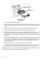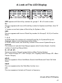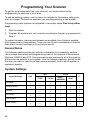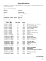
1
Precautions
Before you use this scanner, please read and observe the following.
IMPORTANT!
This scanning radio has been manufactured so that it will not tune to the radio
frequencies assigned by the FCC for cellular telephone usage. The Electronic
Communications Privacy Act of 1986, as amended, makes it a federal crime to
intentionally intercept cellular or cordless telephone transmissions or to market this
radio when altered to receive them. The installation, possession, or use of this
scanning radio in a motor vehicle may be prohibited, regulated, or require a permit
in certain states, cities, and/or local jurisdictions. Your local law enforcement
officials should be able to provide you with information regarding the laws in your
community.
Changes or modifications to this product not expressly approved by Uniden, or
operation of this product in any way other than as detailed by this Operating Guide,
could void your authority to operate this product.
EARPHONE WARNING!
Be sure to use only a monaural earphone or 32 Ω stereo headset. Use of an
incorrect earphone or stereo headset might be potentially hazardous to your
hearing. The output of the phone jack is monaural, but you will hear it in both
headphones of a stereo headset.
Set the volume to a comfortable audio level coming from the speaker before
plugging in the monaural earphone or a stereo headset of the proper impedance
(32 Ω). Otherwise, you might experience some discomfort or possible hearing
damage if the volume suddenly becomes too loud because of the volume control or
squelch control setting. This might be particularly true of the type of earphone that
is placed in the ear canal.
WARNING!
Uniden does not represent this unit to be waterproof. To reduce the risk of fire
or electrical shock, do not expose this unit to rain or moisture.
Astro® , DPL® , Digital Private Line®, Motorola ® , PL®, PRIVACY PLUS ® , Private
Line® , SMARTNET® , and SMARTZONE® are registered trademarks of Motorola,
Inc.
2
LTR ® is a registered trademark of E.F. Johnson Co.
EDACS ® is a registered trademark of M/A-COM Private Radio Systems Inc.
Uniden ® and Bearcat® are registered trademarks of Uniden America Corporation.
Trunk Tracker™, Trunk Tracking™, and Close Call™ are proprietary trademarks of
Uniden America Corporation.
Other trademarks used throughout this manual are the property of their respective
holders.
Power Related Issues
Important: To prevent memory from being corrupted, do not unplug the AC
adapter during the time the memory is accessed for programming or auto store.
Notes:
• If when you connect the AC adapter the [VOL] /Power Switch is ON, the
scanner may not power on. Should this occur, simply turn the control OFF, then
ON again.
• If the scanner loses power (as when you turn off your car’s ignition with the
scanner’s power switch on), it can lose some system settings such as display
color and backlight. To ensure that such settings persist, either change the
setting using the scanner’s menu or power the scanner off then back on using
the power switch after making such setting changes.
• When you turn off the scanner using the power switch, the scanner remembers
the last settings and mode. When you turn power back on, it resumes the
previous mode.
Precautions
3
Table of Contents
Precautions .......................................................................................................................................... 2
Power Related Issues....................................................................................................................... 3
The FCC Wants You to Know ............................................................................................................. 9
Scanning Legally ................................................................................................................................. 9
Introduction ........................................................................................................................................ 12
Feature Highlights ............................................................................................................................. 13
General........................................................................................................................................... 13
Trunk Tracking................................................................................................................................ 15
Searches and Scanning.................................................................................................................. 16
GPS................................................................................................................................................ 17
Weather .......................................................................................................................................... 17
Memory Storage Limits...................................................................................................................... 18
Search Lockout Limits ....................................................................................................................... 18
About This Manual............................................................................................................................. 18
How the Scanner’s Controls Are Represented in This Manua.......................................................l 18
A Short User’s Guide to Assist the First-Time Scanner Enthusiast ............................................. 20
Understanding Scanning and the BCT15 ........................................................................................
Understanding the Scanner’s Memory..............................................................................................
Understanding Quick Keys................................................................................................................
What is Scanning?.............................................................................................................................
What is Searching? ...........................................................................................................................
What is CTCSS/DCS?.......................................................................................................................
Conventional Scanning......................................................................................................................
Simplex Operation.............................................................................................................................
Repeater Operation...........................................................................................................................
What is Trunk Tracking?....................................................................................................................
Trunked Scanning .............................................................................................................................
Startup Configuration.........................................................................................................................
Multi-Site Trunking.............................................................................................................................
Types of Trunking Systems ...............................................................................................................
Motorola Trunking...........................................................................................................................
EDACS Trunking.............................................................................................................................
LTR Trunking..................................................................................................................................
Where To Get More Information........................................................................................................
Information On The Internet............................................................................................................
22
22
22
23
23
23
24
24
25
25
26
26
27
27
27
28
29
30
30
Included With Your Scanner ............................................................................................................. 31
Setting Up Your Scanner ...................................................................................................................
Base Station ......................................................................................................................................
Setting Up an Audio Recording Device or Computer Recording.......................................................
Vehicle Installation.............................................................................................................................
Mounting Using the Bracket............................................................................................................
Mounting Using the Optional DIN-E Sleeve....................................................................................
Removing the Scanner from the DIN-E Sleeve ..............................................................................
Mounting Using ISO Technique......................................................................................................
Removing the Display Sticker.........................................................................................................
Connecting an Optional Antenna.......................................................................................................
4
32
32
34
34
34
35
37
37
38
38
Controls, Keys, and Functions.......................................................................................................... 40
A Look at The LCD Display ................................................................................................................ 47
Tones ................................................................................................................................................... 49
Operation.............................................................................................................................................
Turning On the Scanner and Setting the Squelch..............................................................................
Setting the Display Backlight..............................................................................................................
Setting Alert Mute...............................................................................................................................
Temporary Alert Mute......................................................................................................................
Continuous Alert Mute.....................................................................................................................
Entering Text Within A Menu Option..................................................................................................
Startup Key Operation........................................................................................................................
Conventional....................................................................................................................................
Trunked ...........................................................................................................................................
Service Range.................................................................................................................................
Custom Range.................................................................................................................................
50
50
50
50
50
50
51
51
51
51
51
52
Introduction to BearTracker Operation ............................................................................................
Using BearTracker Scanning.............................................................................................................
The BearTracker Scanning Icons.......................................................................................................
Using the BearTracker Warning System............................................................................................
53
53
54
54
Using the Menu ...................................................................................................................................
General Operations............................................................................................................................
Display Format...................................................................................................................................
Editing a Name...................................................................................................................................
Editing A Frequency...........................................................................................................................
First and Second Menu Levels...........................................................................................................
55
55
56
56
57
57
Programming General Settings.........................................................................................................
Setting and Using the Display Backlight............................................................................................
Setting the Dimmer..........................................................................................................................
Adjusting the Key Beep......................................................................................................................
Setting the Audio AGC.......................................................................................................................
Setting the Display Orientation...........................................................................................................
Adjusting the Display Contrast...........................................................................................................
Setting the GPS Format.....................................................................................................................
Setting the BearTracker Options........................................................................................................
Set Hold Time..................................................................................................................................
Set Delay Time................................................................................................................................
Set Attenuator..................................................................................................................................
Set Alert Level .................................................................................................................................
Set Alert Tone..................................................................................................................................
Set Record.......................................................................................................................................
Max Priority Scan ............................................................................................................................
BearTracker Shortcut Options.........................................................................................................
Setting the Serial Port Speed.............................................................................................................
Displaying Scanner Information.........................................................................................................
Viewing Memory Used.....................................................................................................................
Viewing the Firmware Version and Electronic Serial Number.........................................................
Initializing the Scanner’s Memory ......................................................................................................
Connecting Your Scanner to a Personal Computer...........................................................................
59
59
59
60
60
60
60
61
61
61
62
62
62
62
63
63
63
64
64
64
64
65
65
5
Volume/Squelch with PC Control .................................................................................................... 65
Wired Cloning..................................................................................................................................... 66
Programming Your Scanner .............................................................................................................. 68
System Settings............................................................................................................................... 68
System Options ............................................................................................................................... 69
Site Option Settings ......................................................................................................................... 70
Channel Option Settings.................................................................................................................. 70
Programming Conventional Systems................................................................................................. 71
Programming Trunked Radio Systems .............................................................................................. 71
Programming System Settings........................................................................................................... 72
Editing the System Name ................................................................................................................ 72
Specifying the Correct System Type ............................................................................................... 72
Editing the System Name ................................................................................................................ 73
Programming System Options ......................................................................................................... 73
Assigning a Conventional System to a State................................................................................... 78
Programming Sites............................................................................................................................. 81
Assigning a Trunked System to A State .......................................................................................... 86
Programming Channel Groups .......................................................................................................... 87
Setting Up a Channel Group ........................................................................................................... 87
Editing a Channel Group Name ....................................................................................................... 87
Editing Channels ............................................................................................................................. 88
Locking Out Channel Groups .......................................................................................................... 88
Deleting Channel Groups ................................................................................................................ 88
Programming Channels ..................................................................................................................... 89
Creating a Channel.......................................................................................................................... 89
Editing the Channel Name (Alpha Tag) ........................................................................................... 89
Editing Frequencies ......................................................................................................................... 90
Editing the Talk Group ID ................................................................................................................ 90
Selecting CTCSS/DCS Tones ......................................................................................................... 91
Quick CTCSS/DCS Save ................................................................................................................ 91
Setting Channel Modulation Method ............................................................................................... 91
Setting Channel Attenuation ............................................................................................................ 92
Setting Channel Priority ................................................................................................................... 92
Setting Channel Alert....................................................................................................................... 93
Set Record......................................................................................................................................... 93
Searching and Storing ....................................................................................................................... 96
Service Search................................................................................................................................... 96
Quick Search...................................................................................................................................... 97
Custom Search .................................................................................................................................. 97
Editing a Custom Search Range........................................................................................................ 98
Search With Scan .............................................................................................................................. 99
Set Delay Time................................................................................................................................. 100
Set Attenuator.................................................................................................................................. 101
Set Record....................................................................................................................................... 101
Assigning a Search Range to a Search Key .................................................................................... 101
Saving a Found Channel (Quick Save)............................................................................................ 101
Auto Search and Store..................................................................................................................... 102
Selecting a System........................................................................................................................ 102
Conventional Search and Store..................................................................................................... 102
6
Trunked Search and Store ............................................................................................................ 103
Using the Close Call Feature........................................................................................................... 104
Setting Close Call Options ............................................................................................................... 104
Close Call Hits.................................................................................................................................. 106
Close Call Hits with Scan................................................................................................................. 107
Search and Close Call Options ....................................................................................................... 108
Managing Locked-Out Frequencies .............................................................................................. 108
Unlocking All Frequencies............................................................................................................. 109
Reviewing Locked Out Frequencies.............................................................................................. 109
Searching for Subaudible Tones ................................................................................................... 109
Screening Out Broadcast Sources ................................................................................................ 110
Finding Repeater Output Frequencies .......................................................................................... 111
Setting the Maximum Auto Store Value......................................................................................... 111
Setting the Modulation Type......................................................................................................... 111
Setting Attenuation ........................................................................................................................ 112
Setting Data Skip........................................................................................................................... 112
Setting the Delay Time.................................................................................................................. 113
Setting the Search Frequency Step............................................................................................... 113
Setting Record............................................................................................................................... 113
Priority Scan..................................................................................................................................... 114
Using Weather Aler t (SAME) ........................................................................................................... 115
Searching For a Weather Broadcast................................................................................................ 115
Turning Weather Scan Alert On/Off................................................................................................. 115
Programming a SAME Group .......................................................................................................... 116
Setting WX Alert Priority................................................................................................................... 117
Fire Tone-Out Introduction .............................................................................................................. 118
Setting Tone-Out Standby................................................................................................................ 118
Setting Up Tone-Out........................................................................................................................ 118
Tone-Out Multi-Channel Monitoring................................................................................................. 120
Setting Tone-Out Record................................................................................................................. 120
Using the BCT15 with a GPS ........................................................................................................... 121
Device Compatibility......................................................................................................................... 121
Connecting Your Scanner to a GPS Device .................................................................................... 121
Initial Scanner/GPS Operation......................................................................................................... 121
Location-Based (GPS) Scanning..................................................................................................... 122
Another Example of Multiple Site Creation ...................................................................................... 123
Non-Radio Location Based GPS Features ...................................................................................... 123
Setting the Options........................................................................................................................... 124
For POI Only.................................................................................................................................. 125
For Dangerous Xing, and Dangerous Road Only ............................................................................ 125
Deleting a Location .......................................................................................................................... 126
GPS Display Mode........................................................................................................................... 127
GPS Review Location Mode............................................................................................................ 128
Care and Maintenance ..................................................................................................................... 129
General Use..................................................................................................................................... 129
Location............................................................................................................................................ 129
Cleaning........................................................................................................................................... 129
Birdies .............................................................................................................................................. 129
7
Troubleshooting ............................................................................................................................... 130
Specifications................................................................................................................................... 133
Reference.......................................................................................................................................... 136
Preset Fleet Maps ............................................................................................................................ 136
User Defined Fleet Maps ................................................................................................................. 138
Type I Programming Information................................................................................................... 138
Size Code Restrictions .................................................................................................................. 139
CTCSS Frequencies ........................................................................................................................ 139
DCS Codes ...................................................................................................................................... 140
Index...................................................................................................................................................141
One-Year Limited Warranty............................................................................................................. 145
8
The FCC Wants You to Know
This scanner has been tested and found to comply with the limits for a scanning
receiver, pursuant to Part 15 of the FCC Rules. These limits are designed to
provide reasonable protection against harmful interference in a residential
installation. This scanner generates, uses, and can radiate radio frequency energy
and, if not installed and used in accordance with the instructions, may cause
harmful interference to radio communications.
There is no guarantee that interference will not occur in a particular installation. If
this scanner does cause harmful interference to radio or television reception,
which can be determined by turning the scanner on and off, you are encouraged to
try to correct the interference by one or more of the following measures:
• Reorient or relocate the receiving antenna
• Increase the separation between the scanner and the receiver
This device complies with Part 15 of the FCC Rules . Operation is subject to the
following two conditions: 1) This device may not cause harmful interference, and 2)
this device must accept any interference received, including interference that may
cause undesired operation.
Scanning Legally
Your scanner covers frequencies used by many different groups, including police
and fire departments, ambulance services, government agencies, private
companies, amateur radio services, military operations, pager services, and
wireline (telephone and telegraph) service providers. It is legal to listen to almost
every transmission your scanner can receive. However, there are some
transmissions that you should never intentionally listen to. These include:
• Telephone conversations (cellular, cordless, or other private means of
telephone signal transmission)
• Pager transmissions
• Any scrambled or encrypted transmissions
According to the Electronic Communications Privacy Act (ECPA), you are subject
to fines and possible imprisonment for intentionally listening to, using, or divulging
the contents of such a conversation unless you have the consent of a party to the
conversation (unless such activity is otherwise illegal). This scanner has been
designed to prevent the reception of cellular telephone transmissions and the
decoding of scrambled transmissions. This is done to comply with the legal
requirement that scanners be manufactured so they are not easy to modify to pick
The FCC Wants You to Know
9
up these transmissions. Do not open your scanner’s case to make any
modifications that could allow it to pick up transmissions that are illegal to monitor.
Modifying or tampering with your scanner’s internal components or using it in a
way other than as described in this manual could invalidate your warranty and void
your FCC authorization to operate it.
In some areas, mobile and/or portable use of this scanner is unlawful or requires a
permit. Check the laws in your area. It is also illegal in many areas (and a bad idea
everywhere) to interfere with the duties of public safety officials by traveling to the
scene of an incident without authorization.
A license is required to use this product in Canada.
10
BCT15 Quick Start Guide
To help you enjoy the features and performance of your BCT15 as fast as possible,
follow the steps below. See the content of the manual if you need additional
information.
1.
Mount the scanner and connect power.
2.
Attach the antenna.
3.
Rotate the [VOL] control clockwise past the click to a midpoint.
4.
Rotate [SQ/STATE] to its minimum position.
5.
Press the [SQ/STATE] knob.
6.
Rotate the Scroll Control knob until your state is highlighted.
7.
Press the Scroll Control knob to set your selection.
You are now set to receive transmissions from your state. Other states are locked
out.
Using the chart below, press [POL/DOT], or [HP/B] to receive the type of
agencies.
POL includes Police and Sheriff services.
DOT includes the states’ Department of Transportation services.
HP includes the Highway Patrol, State Police, State Patrol, and State intercity.
B activates the BearTracker Warning System and its associated alert feature.
BearTracker System Key Options
Press X to enable
[POL /DOT]
[HP/B ]
1X
POL
HP
2X
DOT
HP/B
3X
POL & DOT
HP & B
4X
NONE
NONE
The BearTracker Warning System is a special part of the BearTracker System.
This system alerts you to transmissions on frequencies used by ‘mobile extender’
radios as well as by car-to-car, aircraft-to-car, and other special-purpose
frequencies. You receive an audible (beep tone) and visual (flashing Alert light)
alert whenever you are within an approximate three-mile radius of Highway
Patrol/State Police units using a mobile extender unit.
BCT15 Quick Start Guide
11
Introduction
Your BCT15 scanner is a state-of-the-art scanner radio with Trunk Tracker™ III
and automatic scanning capabilities. You can store in the dynamic memory
conventional frequencies such as police, fire/emergency, marine, air, amateur, and
other communications. You can store and scan services that use Trunked Radio
Systems and so much more. You can use the scanner’s Scroll Control to quickly
select channels and frequencies, and you can automatically program channels in a
system using the AutoStore feature. Use your scanner to monitor:
• Analog trunked public safety systems (unencrypted only) *
• Police and fire departments (including rescue and paramedics)
• NOAA weather transmissions
• Business/Industrial radio and utilities
• Marine and Amateur (ham radio) bands
• Railroad
• Military and Civilian Aircraft
Your scanner can monitor the following bands
Frequency
(MHz)
Lower Edge
25.0000
Frequency
(MHz)
Upper Edge
26.9600
AM
5.0
26.9650
27.4100
28.0000
29.7000
50.0000
54.0000
72.0000
76.0000
88.0000
108.0000
137.0000
144.0000
148.0000
150.8000
162.0000
174.0000
216.0000
225.0000
380.0000
27.4050
27.9950
29.6800
49.9900
53.9800
71.9500
75.9950
87.9500
107.9000
136.9750
143.9875
147.9950
150.7875
161.9950
173.9875
215.9500
224.9800
379.9750
399.9875
AM
AM
NFM
NFM
NFM
WFM
FM
WFM
FMB
AM
NFM
NFM
NFM
NFM
NFM
WFM
NFM
AM
NFM
5.0
5.0
20.0
10.0
20.0
50.0
5.0
50.0
100.0
25.0
12.5
5.0
12.5
5.0
12.5
50.0
20.0
25.0
12.5
12
Modulation
Step (kHz)
Comments
Petroleum Products & Broadcast
Pickup
CB Class D Channel
Business & Forest Products
10 Meter Amateur Band
VHF Low Band
6 Meter Amateur Band
VHF TV Broadcast 2 - 4
Intersystem & Astronomy
VHF TV Broadcast 5 - 6
FM Broadcast
Aircraft Band
Military Land Mobile
2 Meter Amateur Band
Military Land Mobile
VHF High Band
Federal Government
TV Broadcast 7 - 13
1.25 Meter Amateur Band
UHF Aircraft Band
Military Band
Frequency
(MHz)
Lower Edge
400.0000
406.0000
420.0000
450.0000
470.0000
764.0000
794.0000
806.0000
849.0125
894.0125
1240.0000
Frequency
(MHz)
Upper Edge
405.9875
419.9875
449.9875
469.9875
512.0000
775.9875
805.9875
823.9875
868.9875
956.0000
1300.0000
Modulation
NFM
NFM
NFM
NFM
NFM
NFM
NFM
NFM
NFM
NFM
NFM
Step (kHz)
12.5
12.5
12.5
12.5
12.5
12.5
12.5
12.5
12.5
12.5
25.0
Comments
Miscellaneous
Federal Government Land Mobile
70 cm Amateur Band
UHF Standard Band
UHF TV
Public Service Band
Public Service Band
Public Service Band
Public Service Band
Public Service Band
25 cm Amateur Band
The frequency ranges shown are based on factory-default step settings. Step
setting changes are user definable.
• The modulation setting are default settings. The user can select from AM / FM
/ NFM / WFM / FMB/ AUTO.
• You can select AUTO for modulation or step settings. If selected, the radio
uses table values.
• If you set the step to 15 kHz, programmable frequencies are then set to steps
of xxx.x000, xxx.x150, xxx.x300, xxx.x450, xxx.x600, xxx.x750, and xxx.x900.
For example, the next frequency of 400.0900 MHz is 400.1000 MHz.
• If you set the step to 8.33 kHz, programmable frequencies are then set to
steps of xxx.x000, xxx.x083, xxx.x166, xxx.x250,xxx.x333, xxx.x416, xxx.x500,
xxx.x583, xxx.x666, xxx.x750, xxx.x833, and xxx.x916.For example, the next
frequency of 100.0916 MHz is 100.1000 MHz.
• If you set the step to 7.5 kHz, frequencies between 150.8150 and
154.6250 MHz must be multiples of 7.5 kHz based on 150.8150 MHz. For
example, the next frequency after 150.8100 MHz is 150.8150 MHz. The next
frequency after 154.6250 MHz is 154.6275 MHz.
Feature Highlights
General
2500 Dynamically Allocated Channels in Up To 500 Systems — provides you
with plenty of room for all your local action.
BearTracker™ Warning System — alerts you when channels normally used by
public safety systems are in use nearby.
Introduction
13
State-by-State Preprogrammed Channels — let you easily keep up with activity
on local police, Department of Transportation, and Highway Patrol frequencies
when you travel, without having to program any channels.
Close Call™ RF Capture Technology — instantly detects and tunes to nearby
transmissions with no additional programming.
Close Call Do Not Disturb — checks for Close Call activity in between channel
reception so active channels are not interrupted
Close Call Temporary Store — temporarily stores and scans the last 10 Close
Call hits so that you can continue to monitor activity on these frequencies, even
after you are out of Close Call detection range.
100 System Quick Keys with 10 Channel Group Quick Keys per system —
makes it easy to listen to or quickly lock out those systems or groups you do not
want to scan.
Lockout Options — with several different and easy lockout options, you can
quickly make your choices to lockout or unlock services.
Temporary Lockout — provides you with a fast means to automatically unlock
temporarily locked out channels/systems when you cycle power.
Receives 25-512, 764-805, 806-956, and 1240-1300 MHz — (excluding cellular
frequencies) the scanner receives the most popular and useful ranges.
DIN-E and ISO Vehicle Mountable — using a optional DIN-E sleeve (Part
Number DIN-0001 not provided) or a standard ISO technique, the scanner can be
easily mounted in most vehicles.
Broadcast Screen — using this option you can ignore Close Call or Search hits in
Pager, FM, UHF TV, VHF TV, NOAA Weather, or custom set bands.
Data Skip — helps you to be more free from unwanted data transmissions and
reduces ‘birdies.’
Duplicate Input Alert — warns you if you attempt to input duplicate data for a
name, frequency, or other item.
Fire Tone-Out — alerts you if a two-tone sequential page is transmitted.
Frequency Auto Store — lets you automatically store a newly found frequency
during a search.
3-Level Display and Keypad Backlight — makes it easy to use the scanner at
night.
14
Tone Volume Adjust — lets you select and set various tones for different
purposes. You can adjust the level of the following tones: Key Beep, BearTracker
Alert, Emergency Alert, Channel Alert, Close Call Alert, Tone-Out Detection Alert,
and Location Alert.
PC Control — lets you can connect the scanner to the serial port of your PC and
control the scanner with special software.
Wired Clone — makes it easy to transfer data from one scanner to the other such
as memory information and menu settings.
Memory Backup — feel confident of secure settings because the scanner’s
memory is backed up during operation and retained when power is turned off.
Audio AGC — helps to balance the audio level from different sources.
Record Out — you can connect an output jack to a VOX controlled recorder or PC
sound input to record the received audio.
Orange Wire Vehicle Connection — a special wire lets you connect to the
dimmer circuit of your vehicle so the vehicle’s dimmer also dims the scanner’s
lighting.
Startup Configuration — lets you easily change the scanner’s operation for
different areas.
Trunk Tracking
Trunk Tracker III — you can scan the following trunked systems: Motorola Type I
800 MHz, Motorola Type II 800, 900 MHz, UHF, VHF, EDACS WIDE, NARROW,
and SCAT, and LTR
Control Channel Only — eliminates the need to program voice channel
frequencies for Motorola systems.
Multi-Site Trunking Support — lets you program the scanner to share trunked
system channels across multiple sites, and turn on and off each site independently
so that you can select the best site to scan for your area without duplicating
channels.
ID Auto Store — you can store a new TGID found during a search into a specified
system.
Quick Search — lets you continue a search starting from a current frequency in a
conventional system or from a current trunked channel TGID in a trunked system.
Introduction
15
Name Editing — you can edit or change names, using up to 16 characters, for the
following attributes:
System, Site, Group, Channel, TGID, GPS Location, Custom Search Range,
SAME Group (weather), and Tone-Out.
Trunking Activity Indicators — show you trunking activity when you hold on a
control channel.
Searches and Scanning
Attenuator — lets you reduce by 20 dB the strength of a strong signal to help
eliminate weak reception or interfering transmission.
Alert Mute — you can disable alerts based on a BearTracker priority channel,
Emergency Alert, Close Call, Tone-Out, and GPS.
Alert Plus Scan — lets you listen to only alerts from BearTracker systems or
groups, Close Call, Weather (WX), and GPS.
Channel Alert — lets you assign a tone to a channel so that when the channel
becomes active, the tone sounds.
Channel Memory Scan — you can scan conventional and trunked system
channels at the same time with programming.
CTCSS/DCS Search — quickly determines the CTCSS/DCS sub-audible tones
used by an agency.
Convenient Lockout — lets you lockout any system, site, group, or channel so
that item is skipped during scanning. If a system, site, or group is locked, the
channels of that entity will be skipped.
Custom Search — lets you program up to 10 search ranges and scan each in
order.
Dropout Delay — lets you set a time value so that you don’t miss a reply at the
end of a transmission. The value can be set for systems (all channels share the
same value), as well as Search, Close Call, and Tone-Out settings.
Priority Plus — this option lets you scan and hear only priority channels.
Priority Scan — lets you designate conventional channels as priority so during
scanning, they are checked every 2 seconds.
Repeater Reverse — using one key, you can choose to listen to the input
frequency of a conventional or trunked system.
16
Search With Scan — lets you monitor a service search and a custom search scan
sequentially.
Service Search — lets you select from a list of the most popular services (Public
Safety, News, HAM Radio, Marine, Railroad, Air, Citizens Band Radio,
FRS/GMRS, Racing, TV Broadcast, FM Broadcast, Military Air, and Special,) and
set up your search within that range.
Scan Speed — you can scan at a maximum speed of 100 channels per second in
Scan Mode.
Turbo Search — in regular Search Mode the scanner checks at a maximum value
of 100 steps per second while in Turbo Mode, the rate rises to 300 steps per
second and sets the step to 5 kHz automatically which provides you with greater
ability to hear more.
Search Key — you can assign three keys to initiate a search range.
GPS
Location Based Scanning — using a connected, optional GPS, you can easily
listen to systems as you travel.
GPS (Location Based) Alerts — notify you when you near an area you have
programmed as a dangerous road, dangerous intersection, or a general point of
interest.
Weather
Weather and SAME/FIPS Alert — the scanner receives your area NOAA
broadcast and can be programmed to receive SAME Event Codes and FIPS
codes for area specific data.
WX Priority — you will know immediately when a weather alert is transmitted on a
NOAA weather channel.
WX Scan — lets to quickly find the best weather channel for your geographic
location.
Introduction
17
Memory Storage Limits
Systems
500
Sites
1000
256
20
Channels in a Conventional
System
1000
Channel Groups
in a System
Sites in A System
2500
Channels in a Trunked
System
250
Channels —
All Systems
Trunked Frequencies
Per Site*
750-1000
* depending on the number of TGID in the system.
Search Lockout Limits
Fr equencies
500
Temporary L/O
Fr equencies
250
Permanent L/O
Frequencies
250
Skipped
Search Mode
Close Call Mode
Review
Menu Mode
About This Manual
The screen displays used in this manual are representations of what might appear
when you use your scanner. Since what you see depends on the frequencies and
user IDs for your area and the settings you select, you might notice some
differences between what is in this manual and what appears on your scanner.
To get the most from this manual, review the contents to become familiar with the
basic functions available. If you are new to scanning or trunk tracking, start with
the following short introduction to scanning and follow-up with the enclosed
reprinted article on Programming provided with the courtesy of Popular
Communications magazine.
How the Scanner’s Controls Are Represented in This
Manual
To help navigate the scanner’s menus, the steps shown in this manual show the
displays you see and the keys you press or control you operate to get a desired
result. We use a form of shorthand symbols to save space.
The following example shows you how to use the scanner’s menu to edit an
existing system name. It shows you the key to press in bold and in brackets
[MENU] to select a menu option and the option you see on the LCD in bold Courier
18
type (Program System ) when you press [MENU]. It also instructs you to turn the
Scroll Control (shown as
) to view a series of choices then press or tap the
Scroll Control (the action shown as F to enter a choice (Edit Name).
[MENU]
Program System
F
Select the system
F
Edit Name
F Then, edit the system name.
Introduction
19
A Short User’s Guide to Assist the First-Time
Scanner Enthusiast
Welcome to the family of Uniden scanner users. You have just unpacked your
Uniden BCT15 scanner. You are anxious to scan and hear something so you
rotate the [VOL/POWER] control and wait a moment as the opening Message and
Copyright screens confirm the model information. Then, if you live in a residential
area, you probably hear nothing or very little. Why? The reason is simple. The
programmable BCT15 does not instinctively know where you are and what you
wish to listen to.
Take a few minutes to assist in the ‘educating your scanner’ process so you can
enjoy listening for the first time and feel good about your purchase.
Before proceeding, first set the volume and the squelch levels. Once set correctly,
these settings let you listen at a comfortable level and let the scanner provide a
signal whose strength is sufficient to be heard clearly. Always be sure to connect
the provided antenna or an external (optional) antenna.
There are several options that quickly assure you that your scanner works.
The easiest is to activate the scanner’s Weather System (following) or
BearTracker System on Page 52. Follow these steps to tune to the nearest NOAA
(National Oceanic and Atmospheric Administration) broadcast.
[MENU]
WX Operation
F
The scanner changes to the local NOAA weather channel for your area. Although
there are ten channels, one will be received best for any given location.
Press [SCAN/SEARCH] to exit WX mode.
Once you establish that the scanner operates using the NOAA information, you
can next begin monitoring one of the services within the BearTracker System.
The Uniden BearTracker System makes it easy for you to start scanning other
services, especially for the traveler. We have preprogrammed the BCT15 with the
system data on a state-by-state United States mainland basis.
Refer to the enclosed reprint of the article from Popular Communications dealing
with scanner programming.
To correctly program the BCT15 scanner begin on Page 68. The two essential
programming steps are
1. Plan the system
20
2.
Program the system based on the plan.
The reprinted article from Popular Communications, describes, in clear,
easy-to-understand language, how to start the programming session. The article
also includes a glossary of terms and other valuable data. Be sure to take time out
to look it over before proceeding.
To provide you with useful sized worksheets and instructions to complete them, we
have established links at our company website. Visit, http://www.uniden.com/scanners
to see a list of helpful forms. But first, visit http://www.radioreference.com and locate
the system nearest your location that you want to scan. If you register and pay a small
fee, you can download a ready-to-use formatted PDF complete with the data from your
selected system. Otherwise, you can print the blank worksheet on our web page as
you would any other web based page.
The programming data of a large metropolitan area may consist of many pages
depending on how extensive the area’s Public Service System Talkgroups are.
Don’t be overwhelmed. Begin by choosing the Talkgroups of interest to you.
Transfer the data from the Radio Reference sheets to the appropriate work sheet,
finally programming the data into the scanner.
You can visit one of the Radio Reference forums and potentially learn of someone
in your immediate area who has programmed the same model scanner in your
area. Then, by using the Clone feature or by exchanging files that you each have
transferred to a computer using the Uniden Advanced Scanner Director (UASD)
software you can install the programmed data into your scanner. Once you have
either programmed or selected the option that lets you start experiencing
scanning, spend the next few minutes learning the basics of trunk tracking for an
even more complete listening appreciation.
A Short User’s Guide to Assist the First-Time Scanner Enthusiast
21
Understanding Scanning and the BCT15
This section provides you with additional background on how scanning works and
how your scanner provides that feature. You don’t really need to know all of this to
use your scanner, but some further background knowledge will help you get the
most from your BCT15.
Understanding the Scanner’s Memory
Your scanner’s memory is organized in an architecture called Dynamic Allocated
Channel memory. This type of memory is organized differently and more efficiently
than the bank/channel architecture used by traditional scanners. Dynamic
Allocated design matches how radio systems actually work much more closely,
making it easier to program and use your scanner and determine how much
memory you have used and how much you have left.
Instead of being organized into separate banks and channels, your scanner’s
memory is contained in a pool. You simply use as much memory as you need in
the pool to store as many frequencies, and talk group ID’s as desired. No memory
space is wasted, and you can tell at a glance how much memory you have used
and how much remains.
With a traditional scanner, when you program it to track a trunked system, you
must first program the frequencies. Since you can only program one trunking
system per bank in a traditional scanner, if there were (for example) 30
frequencies, the remaining channels in the bank are not used and therefore
wasted. Also, since some trunked systems might have hundreds of talk groups,
you would have had to enter those types of systems into multiple banks in order to
monitor and track all the ID’s.
Understanding Quick Keys
Traditional “Banked” scanners let you select and deselect banks by pressing a
single digit on the keypad. The BCT15 uses a similar method to turn on and off
scanning sites and systems. When you program a system or site, you assign a
quick key (System/Site Quick Key, or SQK) from 0 to 99. You can use the same
quick key for multiple systems, so that the systems are turned on and off together.
To turn a system/site on or off, just press the digit corresponding to the assigned
SQK. For two-digit SQK’s, first press [.No], then enter the two-digit SQK.
The BCT15 lets you assign another quick key to a group of channels within a
system. This group quick key (GQK) can be from [0]-[9]. To turn on and off
channel groups, you press F while the scanner is scanning the system containing
22
the channels, then press the GQK within 2 seconds. Systems can have up to 20
channel groups, and multiple channel groups can be assigned to the same GQK.
What is Scanning?
Unlike standard AM or FM radio stations, most two-way communications do not
transmit continuously. Your BCT15 scans programmed channels until it finds an
active frequency, then stops on that frequency and remains on that channel as
long as the transmission continues. When the transmission ends, the scanning
cycle resumes until the scanner receives another transmission.
What is Searching?
The BCT15 can search each of its 13 service search ranges and up to 10 custom
search ranges to find active frequencies. This is different from scanning because
you are searching for frequencies that have not been programmed into the
scanner’s channels. You set the upper and the lower values of the range and then
the scanner searches for any active frequency within the limits you specify. When
the scanner finds an active frequency, it stops on that frequency as long as the
transmission lasts. If you think the frequency is interesting, you can program it into
the scanner’s memory. If not, you can continue to search.
What is CTCSS/DCS?
Your scanner can monitor systems using a Continuous Tone Coded Squelch
System (CTCSS) and Digital Coded Squelch (DCS) system, which allow squelch
to open only when the tone you have programmed with a specific frequency is
received along with a transmission.
CTCSS and DCS are sub-audible tone signaling systems sometimes referred to
as PL or DPL (Motorola’s trademarked terms for Private Line and Digital Private
Line respectively). CTCSS and DCS are used only for FM signals and are usually
associated with both amateur and commercial two-way frequencies. These
systems make use of a special sub-audible tone that accompanies a transmitted
signal.
CTCSS and DCS are used for many purposes. In many cases, CTCSS and DCS
are used to restrict access to a commercial repeater, so that only those units which
transmit the correct tone along with their signal can “talk” to the repeater.
CTCSS and DCS are also used in areas that receive interference where there are
several stations with output frequencies close to each other. When this occurs, you
might hear multiple communications on the same frequency. The stations might
Understanding Scanning and the BCT15
23
even interfere with each other to the point where it is impossible to clearly receive
any of the stations. A scanner, such as your BCT15, equipped with CTCSS and
DCS, can code each received frequency with a specific sub-audible CTCSS or
DCS frequency or code. Then, when you receive multiple signals, you only hear
the transmission with the CTCSS or DCS tone you programmed. If you do not
receive the correct tone with a signal, the scanner’s squelch remains closed and
you hear nothing.
The tables showing the available CTCSS frequencies and DCS codes are found in
the Reference Section on Page 134 of this manual.
Conventional Scanning
Conventional scanning is a relatively simple concept. Each group of users in a
conventional system is assigned a single frequency (for simplex systems) or two
frequencies (for repeater systems). Any time one of them transmits, their
transmission always goes out on the same frequency. Up until the late 1980s, this
was the primary way that radio systems operated.
Even today, there are many 2-way radio users who operate using a conventional
system:
• Aircraft
• Amateur radio
• FRS/GMRS users
• Broadcast AM/FM/TV stations
• Many business radio users
When you want to store a conventional system, all you need to know is the
frequencies they operate on. When you are scanning a conventional system, the
scanner stops very briefly on each channel to see if there is activity. If there isn’t,
the scanner quickly moves to the next channel. If there is, then the scanner pauses
on the transmission until it is over.
Simplex Operation
Simplex systems use a single frequency for both transmit and receive. Most radios
using this type of operation are limited to line-of-sight operation. This type of radio
is frequently used at construction job sites, and with inexpensive consumer radios
such as GMRS/FRS radios. The range is typically 1-15 miles, depending upon the
terrain and many other factors.
24
Repeater Operation
Repeater systems use two frequencies: one transmits from the radio to a central
repeater; the other transmits from the repeater to other radios in the system. With
a repeater-based system, the repeater is located on top of a tall building or on a
radio tower that provides great visibility to the area of operation. When a user
transmits (on an input frequency), the signal is picked up by the repeater and
retransmitted (on an output frequency). The user’s radios always listen for activity
on the output frequency and transmit on the input frequency. Since the repeater is
located very high, there is a very large line of sight.
Typical repeater systems provide coverage out to about a 25-mile radius from the
repeater location.
What is Trunk Tracking?
Your BCT15 is designed to track the following types of trunking systems.
• Motorola Type I, Type II, Type IIi hybrid, SMARTNET, and PRIVACYPLUS
analog trunking systems, which are extensively used in 800 MHz
communication systems.
• LTR trunking systems
• EDACS SCAT trunking systems
• EDACS trunking systems
When tracking these types of systems, you might want to remember that your
scanner can track more than one trunking system at a time and scan conventional
and trunked systems at the same time.
Conventional scanning is a simple concept. You enter a frequency used by
someone you want to monitor into your scanner’s memory. For example, the police
in your area might transmit on 460.500 MHz, the fire department on 154.445 MHz,
the highway department on 37.900 MHz, etc. So when your scanner stops on a
frequency, you usually know who it is, and more importantly, you can stop on a
channel and listen to an entire conversation. This type of scanning is easy and fun.
However, as the demand for public communications has increased, many public
radio users do not have enough frequencies to meet their needs, creating a
serious problem. Trunking radio systems help solve this problem.
Understanding Scanning and the BCT15
25
Trunked Scanning
While conventional scanning worked great while there were only a few groups
wanting to use the frequencies, with the advent of smaller, lower-cost radios more
and more agencies and businesses wanted to take advantage of the utility of
2-way radio. As a result, the bands that were used most became full, so new users
were not able to take advantage of the technology as quickly as they wanted.
Trunking solved this frequency shortage by allowing multiple groups to use the
same set of frequencies in a very efficient way. While each type of trunking system
operates a little differently (see the next few sections), they all work on the same
basic premise: even in a system with a lot of users, only a few users are ever
transmitting at any one time.
Instead of being assigned a frequency, as with conventional systems, each group
is assigned a talk group ID. A central computer controls the frequency each group
operates on...and this frequency selection is made each time a user transmits. So,
while on a conventional system queries, replies, and follow-ups are all on a single
frequency, they could each be on completely different frequencies on a trunked
system. This semi-random frequency assignment made monitoring such a system
impossible prior to Uniden’s invention of the TrunkTracker scanner.
Startup Configuration
The Startup Configuration option lets you quickly and automatically lock and
unlock systems based on your desired configuration. Simply hold down a number
button while powering on the scanner. Systems assigned to that number are
automatically unlocked and systems assigned to other numbers are automatically
locked. Systems that are not assigned to any startup configuration are left
unchanged.
You could use this feature to give you quick, single-press Quick Key access to
your favorite systems even when you travel to other locations. For example, if you
program your scanner as follows:
System/Site Quick Key
Configuration 1
Configuration 2
1
Fort Worth
Phoenix
2
Tarrant County
Mesa
3
Arlington
Mariposa County
When you are in the Fort Worth area, press [1] while turning on the scanner.
System Quick Keys [1], [2], and [3] then allow you to select between the local
systems. When you travel to the Phoenix area, hold [2] while turning on the
26
scanner. Now, the Fort Worth systems are locked out and System Quick Keys [1],
[2], and [3] allow selection between the Phoenix-area systems.
Multi-Site Trunking
Some systems covering a very large geographic area use multiple antenna sites
that each operate on different frequencies, but that use the same Talk Group ID’s
for traffic. When programming such a system, you program each site’s frequencies
and other settings into the system, then program the channels into channel groups
within that system. Each site can have its own quick key, so you can turn each
individual site on or off while you scan. Since all sites share all the channels within
the system, multi-site trunking is much more efficient than programming each site
as a separate system.
Not only does your BCT15 scan channels like a conventional scanner, it actually
follows the users of a trunked radio system. Once you know and program a talk
group’s ID (TGID), you won’t miss any of the action.
If you are a new scanner enthusiast, you might want to read the first part of this
manual and use your scanner in conventional mode before you begin trunk
tracking. Understanding scanning fundamentals and terminology will make trunk
tracking much easier. If you are already an experienced scanner operator, you can
review the programming worksheets and their associated pages in the Reference
Section of this manual.
Types of Trunking Systems
Trunking systems divide a few frequencies among many different users, but the
way that each system does this is slightly different. This section describes some of
the technical data behind Motorola, EDACS, and LTR trunked radio systems.
Motorola Trunking
All Motorola trunking systems use the same basic trunking method. The system
consists of one control channel (or as many as 4 per system but only one is active
at any one time), plus one or more voice channels (typically 10, 20, or 28 total
channels). When a user presses Push To Talk (PTT) to transmit, their radio first
sends the person’s talk group information to the control channel. The computer
then assigns that talk group to a specific voice channel and transmits that data
over the control channel. All radios in that talk group switch over to the assigned
voice channel and the user can begin speaking. This all typically takes place in
about a second...the person transmitting hears a beep from their radio when the
channel is assigned and then it is OK to start talking.
Understanding Scanning and the BCT15
27
The systems in use are:
Motorola Type I — the radios send the radio ID, the fleet and subfleet talk group
ID to the control channel each time they transmit. To program a Type I system, you
need to know the system’s fleet map. The most common fleet maps are included in
the Reference section in this manual. You can also find fleet map resources on the
web at http://www.radioreference.com for example.
Motorola Type II — the radios only send the radio ID and radio channel code to
the control channel. The central computer keeps a database of radio ID’s and
which talk group is assigned to which channel code for each radio, so with this
system the user’s radio sends only about 1/3 the data as a Type I system with each
transmission. Type II systems do not use Fleet-subfleet talk groups; instead they
use a 5-digit ID for each talk group.
Type IIi Hybrid — these systems support a mix of both Type I and Type II users.
Like Type I systems, you must know the system’s fleet map to ensure proper
tracking.
Motorola ASTRO 25 (APCO 25) — these radios are similar to Type II systems,
but send only the radio ID and radio channel code to the control channel,
transmitting voice in digital form. The BCT15 is not designed to process APCO 25
signals.
EDACS Trunking
EDACS trunking works in much the same way as Motorola trunking with a couple
of major differences. In an EDACS system, each frequency used by the system is
assigned a Logical Channel Number (LCN) so that less data needs to be
transmitted by the control channel. Talk groups are assigned in an
Agency-Fleet-Subfleet (AFS) hierarchy. There is one variation of EDACS called
SCAT (Single Channel Autonomous Trunking) that your BCT15 can monitor.
Logical Channel Numbers — each frequency used by the system is assigned an
LCN. This information is programmed into each user radio. When a user presses
PTT, their radio sends their AFS information to the control channel. The computer
then assigns that talk group to a channel and sends the LCN so that all other
radios in that talk group will switch to the correct channel. To program an EDACS
system in your scanner, you will need to know both the frequencies used by the
system and the LCN for each frequency.
Agency-Fleet-Subfleet — talk group ID’s for EDACS systems are assigned in a
way that makes it easy to see at a glance the affiliation of the user. Each radio is
assigned a 2-digit agency identifier from 00 - 15. For example, 01 might be used
28
by the police, 02 by the ambulance service, 03 by the fire department, and so on.
Each agency is then subdivided up to 16 times to provide fleet identification, and
then 8 more times to identify subfleets.
For example, the complete AFS for the Police Department West District’s dispatch
channel might be 01-062. 01 identifies the agency as the police department, 06
identifies the fleet as the West district, and 2 identifies the subfleet as the dispatch
channel. While these assignments are somewhat arbitrary and vary from system
to system, there are many resources on the web for finding the assignments for
most systems. Because of the logical hierarchy of the AFS system, your BCT15
lets you assign wildcard ID’s that let you, for example, use only one ID memory to
identify all units in either an agency or a fleet.
EDACS SCAT — (Single Channel Autonomous Trunking) systems operate on a
single channel and alternate control data with analog voice traffic. While your
BCT15 cannot track ID’s in this system, it can eliminate the control data so that all
you hear is the voice transmissions when you monitor this type of system.
LTR Trunking
LTR (Logic Trunked Radio) systems are trunking systems used primarily by
business or private communications service providers, such as taxicabs, delivery
trucks, and repair services. These systems encode all control information as digital
sub audible data that accompanies each transmission, so there is no separate
control channel. Users on an LTR system are assigned to specific talk groups,
which are identified by the radio as six digit numbers.
These numbers are in the form AHHUUU, where:
A = Area code (0 or 1)
H = Home repeater (01 through 20)
U = User ID (000 through 254)
When the scanner receives a transmission on a channel set to the LTR mode, it
first decodes the LTR data included with the transmission. In the ID search mode,
the scanner stops on the transmission and displays the talk group ID on the
display. In the ID scan mode, the scanner only stops on the transmission if the LTR
data matches a talk group ID that you have stored in the talk group ID list and have
not locked out. LTR systems are frequently programmed so that each radio has a
unique user ID.
Understanding Scanning and the BCT15
29
Where To Get More Information
By itself, this manual only provides part of what you need to know to have fun
scanning — how to program and use the scanner. Other sources provide
additional information.
Information On The Internet
The Internet is the best source for current frequencies and information about
scanning. Many web sites are dedicated to providing lists of frequencies for your
area. Many have built-in database search engines to assist you.
Make a list of the agencies you want to listen to, then look up the frequencies and
systems used by those agencies. Here are a few useful sites:
• http://www.scannermaster.com * — frequency resources and home of Police
Call.
You can also call them at 1 800 SCANNER (hours are from 10:00 a.m. to 5:00
p.m. Eastern Time Monday through Friday).
• http://www.radioreference.com * — the Internet’s premier source for
user-supported radio system information.
• http://www.bearcat1.com — frequency information from National
Communications.
• http://svartifoss2.fcc.gov/reports/index.cfm * — conventional frequency
information on file with the US Government
• http://groups.yahoo.com/group/BCT15 * — a group for people interested in
discussing the BCT15.
* - These web sites are not affiliated with Uniden Corporation.
For more information about Uniden and our products, visit http://www.uniden.com.
30
Included With Your Scanner
Cigarette Lighter
Adapter Power Cord
AC Adapter
(P/N AD-1009)
BCT15 Scanner
Three Wire DC (with Orange Wire — See Step 6,
“Mounting Using the Optional DIN-E Sleeve)”
Power Cord
Mounting Bracket
and Hardware
Remote PC to Scanner
Cable (scanner plug to
female DB9)
Push-on type
Telescopic Antenna
Owner’s Manual
Other printed
material
If any of these items are missing or damaged, immediately contact your place of
purchase or Uniden Customer Service at: (800) 297-1023, 8:00 a.m. to 5:00 p.m.,
Central Time, Monday through Friday.
Included With Your Scanner
31
Setting Up Your Scanner
These guidelines will help you install and set up your new scanner:
The BCT15 can be placed on a convenient surface in your home as a base station,
and connected to a standard outlet that supplies 120VAC, 60Hz. You must use
either the supplied antenna or an electrically correct outdoor antenna, properly and
safely mounted at your chosen site.
The scanner is also designed to accommodate either DIN-E and ISO-DIN
automotive mounting configurations. A DIN-E sleeve and keys, (Part Number
DIN-0001) are optional and available from Uniden.
The unit can also be placed above or beneath the dash of your vehicle using the
supplied bracket and mounting hardware.
• If your scanner receives interference or electrical noise, move the scanner or
its antenna away from the source.
• To improve the scanner’s reception, use an optional external antenna
designed for multi-band coverage. (You can purchase this type of antenna at a
local electronics store). If the optional antenna has no cable, use 50-75 Ω
coaxial cable for lead-in. A mating plug might be necessary for the optional
antennas.
• Use an optional mono earphone or mono headset with proper impedance
(32 Ω) for private listening. Read the precautions on the inside front cover of
this Owners Manual.
• Do not use the scanner in high-moisture environments such as the kitchen or
bathroom.
• Avoid placing the scanner in direct sunlight or near heating elements or vents.
Base Station
This is the simplest approach to let you get started quickly. Decide on a location
that is convenient to a nearby wall outlet, has desk space to let you complete your
programming worksheets, will safely allow the indoor antenna to be extended, or
near a window to use an outdoor antenna.
32
BCT15
Mounting
Wood
Screws
Desk
Stick-on
Mounting
Feet
To secure the radio, by means of the mounting bracket, to a surface, follow the
steps below:
1.
Attach the four protective rubber feet to the mounting bracket when you use
the scanner on a flat surface. Do not use them when you mount the bracket
using screws.
2.
Use the bracket as a template to mark positions for the two mounting screws.
3.
At the marked positions, drill holes slightly smaller than the screws.
4.
Align the bracket with the threaded holes on the sides of the radio case so the
bracket is beneath the radio. Secure the bracket using the two threaded
knobs. Never overtighten the knobs.
Once the radio is positioned, connect it to a source of AC power using the supplied
13.8V, 750 mA AC adapter. Insert the barrel of the AC adapter to the jack on the
rear, upper right side of the radio marked
.
WARNING!
Use only the Uniden-supplied AC adapter with this scanner.
Insert the connector of the supplied indoor telescoping antenna to the BNC
Antenna Connector and apply moderate pressure to secure it.
Setting Up Your Scanner
33
Setting Up an Audio Recording Device or Computer
Recording
It is best if you plan ahead when you initiate the basic setup of the scanner if you
include the components to record incoming reception. You need an audio
recording device which can be controlled by a Voice Operated module (VOX)
either externally or from within the unit and the correct connecting cable.
The REC (record) jack on the rear apron provides a constant-level audio output
which is not affected by the setting of the volume control. Use a mono or stereo
cable that ends in a 3.5mm plug for the scanner. The recorder might have its own
requirements as to the proper plug. Check the recorder’s instructions to be sure.
Connect the cable to an external or internal VOX control so that the recorder
operates when audio is present.
You can also connect the cable to the appropriate input jack on your PC so that
with controlling software, you can record to your hard disc.
In order for the function to operate, you must set the channel to record. You must
also set the system’s record option to either All Channel, which will record all
channels regardless of any channel’s setting, or Marked Channel which only lets
recording occur if you have selected record for that channel. Which you choose
will depend on various factors.
Vehicle Installation
You can mount your scanner in your vehicle, using either the supplied bracket or
the optional DIN-E sleeve.
Mounting Using the Bracket
With the bracket removed from the radio, use the holes in the bracket as a
template to initially mark the location you plan to use in your vehicle. Be absolutely
certain of what might be behind the mounting surface before making any holes, be
it above, or below, or in front of your dash, armrest console, or other location. If you
drill carelessly, expensive damage can result. If in doubt, consult your vehicle
dealer’s service department or a qualified professional installer.
Important: AVOID AIRBAG DEPLOYMENT ZONES. Ignoring this installation
concern may result in bodily harm and the inability of the airbag to perform
properly.
34
Star
Washers
BCT15
1.
Using appropriate screws or other hardware, secure the bracket.
2.
Insert the scanner and insert the bracket knobs to lock the scanner in position.
3.
Attach the Cigarette Lighter Power Cord to the rear of the scanner and plug
the adapter end into a dash mounted 12V DC socket.
4.
Attach a suitable mounted mobile antenna to the antenna jack on the back of
the scanner.
Mounting Using the Optional DIN-E Sleeve
If you are unsure about how to install your scanner in your vehicle using the
optional DIN-E sleeve, consult your automobile manufacturer, dealer, or a qualified
installer. Before installing, confirm that your scanner fits in the desired mounting
area and you have all the necessary materials to complete the task. Your scanner
requires a 2 x 7-1/8 x 5-5/16 inch (50 x 180 x 135 mm) mounting area.
Allow an additional 2-3/8 inch (60mm) space behind the unit for connectors and
wires.
To purchase the DIN-E sleeve and included Removal Keys, visit
http://www.uniden.com/store/ and order part number, DIN-0001.
Setting Up Your Scanner
35
Opening in dash
DIN E sleeve
BCT15 with outer
case removed
1. Remove the bracket if it is attached.
2. Remove the four Philips screws from four small tabs of the case, on the rear,
that secure the outer metal case and pull off the case (toward the rear) with
care.
3. Install the DIN sleeve into the opening in your dashboard, lip facing out.
4. Push out the top and bottom tabs to hold the sleeve firmly in place.
5. Before inserting the scanner in the sleeve, attach the cable from the previously
mounted antenna. Attach the DC Power leads. RED goes to a positive (+)
connection on your fuse block while BLACK connects to the vehicle’s chassis
ground (-).
6. Connect the ORANGE lead to one side of the headlamp switch so that when
you activate the headlights, the scanner’s LCD display changes intensity. Be
sure all the connections are routed away from any potentially pinching or
slicing sheet metal.
7. Slowly slide the scanner into the sleeve until it locks in place.
8. To remove the unit, fully insert the removal keys into each slot on the left and
right edges of the front panel. Carefully slide the radio from the sleeve.
Note: if you plan to connect a GPS unit or external speaker at a later time, expect
to remove the unit for ease of making those connections.
36
Removing the Scanner from the DIN-E Sleeve
If you plan to connect other devices or wires to the radio, such as a GPS unit, at a
later time, you should plan to remove the scanner from the DIN-E sleeve. This is
easily done using the provided Removal Keys that come with the optional DIN-E
sleeve. See “To purchase the DIN-E sleeve and included Removal Keys, visit
http://www.uniden.com/store/ and order part number, DIN-0001.” on page 35.
Refer to the left illustration that follows, showing the Removal Keys.
Fully insert both Removal Keys into the slots on the left and the right edges of the
radio’s dress panel. You cannot remove the radio with only one key. Press in fully,
and do not twist the keys. The radio will unlock from the sleeve making withdrawal
from the sleeve possible. Store the keys in a safe place for future use.
Removal Keys
Mounting Using ISO Technique
Some vehicles can take advantage of another approach to mounting a radio in a
vehicle, called the ISO technique. However, this technique requires a very detailed
and thorough knowledge of the technique. Therefore, we strongly suggest that if
you have any doubt about your experience and abilities, please consult with a
professional installer who is familiar with the ISO approach to radio installation.
To begin the process, it is first necessary to remove the scanner’s outer metal
sleeve from the inner chassis. Unthread the four screws in the rear of the unit.
Slide the cover toward the rear and off. Once the sleeve is removed, you will see
threaded, metric machine screw holes on either side of the chassis cabinet.
Uniden does not supply these screws. Their diameter, length, and screw type
Setting Up Your Scanner
37
should be chosen by a qualified installer based on the internal vehicle bracket
which will be used in securing the scanner chassis.
Once the original radio is removed from the vehicle dash and the fit of the scanner
is correct, be sure to connect all the power, audio, antenna, and any other cables
or wires, to the scanner before the scanner is secured.
The following illustration is a typical example of the ISO technique and the general
side mounting screw holes often encountered. It does not actually represent the
Uniden scanner nor your vehicle’s mounting bracket. Only a professional installer
will be able to determine the best and correct approach.
Internal brackets
Dash
Removing the Display Sticker
Before you use the scanner for the first time, remove the protective plastic film
over the display.
Connecting an Optional Antenna
The scanner’s BNC connector makes it easy to connect a variety of optional
antennas, including an external mobile antenna or outdoor base station antenna.
Note: Always use 50- or 75-ohm, RG-58, or RG-8, BNC terminated coaxial cable
to connect an outdoor antenna. If the antenna is over 50 feet from the scanner, use
RG-8 low-loss dielectric coaxial cable. Cable loss increases with higher frequency.
Connecting an Earphone/Headphone
For private listening, you can plug a 1/8-inch (3.5 mm) mini-plug earphone or
headphones (not supplied) into the headphone jack on the front of your scanner.
This automatically disconnects the internal speaker. See “Earphone Warning” at
38
the front of the manual for important information about using an
earphone/headphone.
WARNING!
Never connect anything other than the recommended amplified extension
speaker to the scanner’s headphone jack. Damage to the scanner might occur.
Connecting an Extension Speaker
In a noisy area, an optional amplified extension speaker, positioned in the right
place, might provide more comfortable listening. Plug the speaker cable’s 1/8-inch
(3.5-mm) mini-plug into your scanner’s back-panel Ext. Sp. Jack.
WARNING!
Never connect any part of the headphone jack to the antenna jack or connect
the radio to an installation where the antenna and audio connection are
grounded. This might also damage the scanner.
Setting Up Your Scanner
39
Controls, Keys, and Functions
2
6
5 4
1
14
13
15
7
3
9
8
16
10
11
12
17
Each of the knobs and keys on the BCT15 produce several different results
depending upon how you activate them. You can, for example, rotate the knobs as
well as press them. Some keys provide one operation when briefly pressed while
pressing and holding a key or knob gives a different result.
40
Finally, many controls and keys behave differently depending on the mode your
radio is in when you use the key or control. Carefully examine the following table to
separate those actions.
Note: “Press” means press and release briefly. “Press and hold” means press and
hold down for at least 2-seconds. “ F + Press” means Tap or Press the Scroll
Control to put the scanner into Function mode then press the key under
discussion.
Controls, Keys, and Functions
1.
Power VOL, Mute
• Turn to turn the scanner on or off.
• Turn to adjust the volume [VOL].
• Press briefly to enable Alert Mute temporarily. Press briefly again to turn it off.
• Press and hold to enable Alert Mode continuously. Press briefly again to turn it
off.
2.
Squelch [SQ] control, [STATE] Key
• Turn to adjust squelch.
• Press to switch to the State list. Use the Scroll Control to dial to the desired
state. Press F to enter your selection.
3.
Scroll Control, Function Key, Enter Key (see separate Function Plus
listing)
• Turn to select Channel, Frequency, or TGID in HOLD mode.
• Turn to dial to a menu item in MENU mode.
• Turn to select an alpha-numeric character while editing a name in MENU
mode.
• Turn to resume scanning or searching while monitoring.
• Press/Tap to enter FUNCTION mode. Note this approach results in a 4 second
timeout. The scanner then returns to NORMAL mode.
• Press and Hold to latch FUNCTION mode. Press again to release.
• Press to select
F a menu item.
• Press plus turn [VOL] to set backlight.
• Press plus turn Scroll Control to move rapidly to a system or custom search
range.
Controls, Keys, and Functions
41
• Turn to use Alphabet Skip in GPS mode.
• Press to cancel FUNCTION mode and return to NORMAL mode.
4. Function Plus
Several specific actions can be accomplished by pressing F then pressing
another key or pressing F then pressing and holding another key.
F + [MENU]
• Use this combination, in Scan or Scan Hold mode, to switch to the edit menu
for the current system, current search range, or current location data.
• Use this combination to switch to the BearTracker menu, if in the BearTracker
System.
• Use this combination in any other mode to go to the menu for that mode.
F + [L/O]
• Use this combination, to temporarily lockout a current system, current site, or
current search range in Scan or Scan Hold mode. The temporary lockout is
cleared when you turn power off then on.
• Use this combination then press [L/O] twice rapidly to permanently lockout a
system or search range. The permanent lockout remains in effect until you
purposely unlock that system or search range.
• Use this combination to switch to Review Search Lockout from Search, Search
Hold, Close Call Only, and Close Call Hold modes.
• Use this combination except press and hold [L/O] to unlock all systems, sites,
search ranges and Close Call Hits systems and enable all the System Quick
Keys for Scan and Scan Hold modes. The same operation unlocks all
Locations of all types in the Review Location mode for GPS related settings.
F + [1] to [9] and [0] Keys
• Use this combination, in Scan mode, to turn on or off any assigned Group
Quick Key (GQK).
• Use this combination in Scan Hold mode and press [1] to toggle Priority mode
— Off, On, Plus On.
• Use this combination, while in WX Scan or WX Scan Hold, press [2] to toggle
between WX Scan and WX Alert Scan.
• Use this combination, while in any other mode but Scan and GPS. Press [2] to
toggle WX Alert priority on or off. Press and hold [2] to switch to WX Scan
mode.
42
• Use this combination in any mode except Scan and GPS. Press [3] to toggle
Close Call mode. Press and hold [3] to switch to Close Call Only mode.
• Use this combination in any mode except Scan and GPS. Press [4], [5], or [6]
to begin searching the range set when you set up and assigned one of these
keys to a selected search range.
• Use this combination in any mode except Scan and GPS. Press [7] to toggle
the attenuator setting.
• Use this combination in Scan Hold, Search, Search Hold, Close Call Only, and
Close Call Hold modes. Press [8] to monitor the frequency to the site repeater.
The scanner changes back to the frequency from the repeater when you
release [8].
• Use this combination in any mode except Scan and GPS. Press [9] to set Alert
Plus Scan on.
• Use this combination in Scan Hold mode. Press [0] to toggle Name Disp mode
on or off.
F + [.No] Key
• Use this combination in Scan and Scan Hold mode to toggle the Active
Channel Display mode on and off.
F + [SCAN/SEARCH] Key
• Use this combination in Search Hold mode or monitoring in Search mode. Use
to resume searching.
• In all other modes except Search, Search Hold, and GPS, press
[SCAN/SEARCH] to display Quick Search Prompt.
• Use this combination while scanning a trunked system to toggle ID Scan and
ID Search.
Note: This does not work while scanning Bear Tracker system.
5.
POL/DOT Key
• Press to change the group lockout status of Police, Department of
Transportation. Unlocked means enabled for scanning. See the table on
Page 53 for the result of multiple key presses.
6.
HP/B ® BT (BearTracker™) Key
• Press to change the group lockout status of HP (Highway Patrol), and
B BearTracker™. Unlocked means enabled for scanning. See the table on
Page 53 for the result of multiple key presses.
Controls, Keys, and Functions
43
7. GPS (Global Positioning Satellite) Key
• Press to switch to GPS mode.
• Press and hold to store current location data with a connected and enabled
GPS.
8. L/O Key
• Press once to temporarily lockout a system channel, a search frequency, or
location data. The temporary lockout is cancelled when you turn off power.
• Press twice rapidly to permanently lockout a system channel, a search
frequency, or location data. The permanent lockout remains in effect until you
purposely unlock that channel, frequency, etc. Note: this does not apply to a
TGID found during an ID Search using the BearTracker system.
• Press and hold while in Scan or Scan Hold mode to unlock all locked values in
the current system.
• Press and hold to unlock location data in Review Location (GPS) mode.
• Press and hold to unlock all the frequencies of all Search Ranges in Search
mode and Close Call mode.
9. [1] to [9] and [0] Key
• In Scan mode, press the numeric keys to access a set Quick Key for a system
or search range.
• In Custom Search mode, press numeric keys to enable or disable a specific
search range number, applicable only to the search range.
• In All Hold, Close Call, and Tone-Out modes, press the numeric keys to switch
to Direct Entry mode.
• When editing a name, press [4] to move the cursor one character to the left.
Press [6] to move the cursor one character to the right.
10. [.No] Key
• Press to cancel an Error or Warning message.
• Press to input the decimal point for a frequency.
• Press to enter a hyphen when inputting a Talk Group ID.
• Press to enter an ‘i’ as the first character of an I-Call (Individual Call) in Hold,
Close Call Only, and Tone-Out modes.
• Press to enter numeric values for the tens place for a Quick Key.
44
11. [E YES ] Key
• Press to select (enter) data value or a menu selection.
• Press to edit channel data in Scan or Scan Hold modes. Note: does not apply
to BearTracker system.
• Press to capture and store a frequency in Search, Search Hold, Close Call,
Close Call Hold, WX Scan, and WX Scan Hold modes.
• Press to switch to the Edit Menu for a current Tone-Out.
• Press to switch to Review Location mode for GPS operations.
12. [SCAN/SEARCH] Key
• Press to resume scanning while monitoring a channel in Scan Hold mode.
• Press to switch to Scan mode from any mode except Scan Hold, or GPS
mode.
• Press to enable a scan screen from GPS mode.
13. [HOLD/RESUME] Key
• Press to enable a Hold while in the following modes: Scan, Search, Close Call
Only, and WX Scan.
• Press again to toggle to scan mode from a hold.
Note that an error tone sounds in Close Call Only mode if a signal has not yet
been acquired.
14. [MENU] Key
Press then use the Scroll Control to step to various menu listings for option
settings.
15. BNC Antenna Connector
Connect an appropriate outdoor antenna or push on the supplied indoor antenna.
16. External Speaker Jack
Use an mini ( 1/8-inch 3.5mm) audio plug to connect an external amplified speaker
for enhanced listening in noisy environments.
17. 9-Pin Serial Connector for GPS or PC connection
Using the cable from the GPS, connect a compatible unit here. Using a standard
serial cable and possibly a gender changer or null modem adapter, connect a PC
serial port here.
Controls, Keys, and Functions
45
18. DC Power I N
Connect only the supplied AC adapter to this jack. Never use any other AC
adapter as damage might occur.
46
A Look at The LCD Display
GRP appears with Quick Key numbers for groups 0 - 99 in Function mode.
Sx: :
This icon appears with icons of Quick Key number for Systems and Sites ( from “0”
to “99”).
“x” shows current ten’s place of Quick Key for System or Site.
GRP :
This icon appears with icons of Quick Key number for Groups (1 - 9, 0) in Function
Mode.
1 - 9, 0 :
In SCAN mode, the numbers of unlocked Quick Key for Systems/Group are
displayed. And a current scanning number blinks.
In SCAN HOLD mode, the Quick Key number of the current System/Group is
displayed.
The numbers of selected User Ranges appear while Custom Search. And the
number of searching Range blinks.
PL, DT, HP, BT :
These icons show Groups’ lockout status of Bear Tracker System.
(PL = Police Groups, DT = DOT Groups, HP = Highway Patrol Groups, BT = Bear
Tracker Groups)
HOLD :
This icon appears in Scan Hold Mode, Search Hold Mode and Close Call Hold
Mode.
DSKP :
This icon appears when the Data Skip function is on.
L/O :
This icon appears at locked out Channel or frequency.
A Look at The LCD Display
47
PRI :
This icon turns on while the Priority Scan works and this blinks while Priority Plus
works.
GPS :
This icon appears when the scanner receives GPS data.
AM / FM / NFM / FMB / WFM :
These icons show the modulation type. “AM”, “FM”, “NFM”, “FMB” or “WFM” will
appear.
ATT :
This icon appears on the Channel that is Attenuator On.
C67.0 / DCS023 / etc. :
This area displays the information of CTCSS/DCS.
WX :
This icon turns on while the Weather Alert Priority Scan works.
f (Function icon) :
This icon appears while Function Mode.
Function Mode does not have a timeout when this icon blinks.
P (Priority Channel) :
This icon appears when the channel set to “Priority On”.
M (Alert Mute) :
This icon blinks when the scanner is in temporary Alert Mute.
This icon appears when the scanner is in continuous Alert Mute.
S (Signal Indicator) :
This icon shows strength of the signal from 0 to 5.
C (Close Call Pri) :
This icon appears when the Close Call Mode is CC Pri Mode.
This blinks while Close Call Only Mode or when the scanner detects the Close
Call.
c (Close Call DND) :
This icon appears when the Close Call Mode is CC DND Mode.
This is a reverse display of Close Call Pri icon.
48
Tones
The BCT15 produces various tones, beeps, and alert sounds for different reasons.
They are comprised of three fundamental tones: high 1200 Hz, middle 920 Hz, and
low 640 Hz. In addition there are alert sirens and a series of tones whose volume
are user selectable. Some of the more frequently uncounted tones are detailed
below.
General Tones
Key Touch — a single high beep sounds
Confirmation — a double high beep sounds
Enter or Accept — press [EYES] sounds an alternating high, silent, middle beep.
Error — this sounds a high beep, silence, repeated twice.
Weather Alert Tones
Warning — a repeating, rising tone or siren effect sounds.
Watch — a rising tone with a warbling sounds.
Advisory — a rising tone with intermittent silence including the standard 1050 kHz
NOAA tone.
Menu Mode Tones
Rotate the Scroll Control in Menu mode produces a single high beep. Turning
past the last menu item in a sequence sounds a double beep.
A single middle tone beep sounds when you make a menu selection using [EYES]
or F.
Pressing [MENU] to back step to a lower level produces a double, middle tone
beep.
Scanner Alert Tones
There are 9 selectable Alert Tones that you can use to provide notice of activity on
a selected channel using Set Alert or Emergency Alert.
There are four selectable tones available for POI plus two more fixed tones
reserved for Dangerous Xing and Dangerous Road.
Tones
49
Operation
Before you apply power, there are a few basic operations to get the scanner ready.
Those are covered below. If some seem out of a logical order it is only so you can
use the BCT15 more quickly. For example, some of these action are required for
basic programming or menu options.
Turning On the Scanner and Setting the Squelch
To turn the scanner on, rotate [VOL] clockwise. Turn the knob to a comfortable
sound level.
Rotate the squelch control [SQ] clockwise until you either hear a broadcast or
noise just stops. The control is now set for strong signals. If you desire to hear a
weaker signal, turn it counter clockwise from that point until you hear background
noise once more.
Setting the Display Backlight
Press F. f appears on the display. Repeatedly press [VOL] to reach your desired
level from Off, Low, Medium, and High.
Setting Alert Mute
Your scanner provides several varieties of alert tones for various situations such
as a signal received on a BearTracker priority system, a channel alert, an alert for
Close Call detection, and GPS alerts. You can silence their sounding using two
approaches. The Alert LED will light to warn of Priority Channel, or BearTracker
activity. It will also light in conjunction with GPS settings. The Close Call LED lights
in response to Close Call hits.
Temporary Alert Mute
Press [VOL/MUTE]. This mutes the alert action for about 3 minutes. The
the lower left corner of the display flashes to confirm this setting.
Continuous Alert Mute
Press and hold [VOL/MUTE]. The M icon remains on and not flashing.
50
M icon in
Entering Text Within A Menu Option
To enter a letter, turn the Scroll Control until the letter, numeral or other character
you want appears. To move the cursor to the left, press [4]. To move the cursor to
the right, press [6].
To clear a character, press [.No] twice. To clear all characters, press [.No] three
times.
To accept an entry, press or tap the Scroll Control or press [E YES ].
To cancel an entry, press [MENU].
Startup Key Operation
You can setup a Startup Key Configuration so that when you power up, the
scanner can change the lockout state for each system or each site. Navigate to
Set Startup Key there are differences in the menu structure for Trunked and
Conventional systems.
Conventional
[MENU]
Program System
F
Select the system
F
Edit System Option
F
Set Startup Key
F for each system or site.
Trunked
[MENU]
Program System
F
Select the trunked system
F
Edit Site
F
Select a site
F
Set Startup Key
F for each system or site.
Service Range
[MENU]
Search for ...
Edit Service
F
Select a Service range
F
Search with Scan
F
Set Startup Key
F
F
Operation
51
Custom Range
[MENU]
Search for ...
Edit Custom
F
Select a Custom range
F
Search with Scan
F
Set Startup Key
F
F
Assign all the systems/sites that you want to scan at the same time to the same
key. You can use one key [0] to [9] for each. To use the Startup Key feature, hold
down the key while you turn on power or shortly thereafter.
52
Introduction to BearTracker Operation
Using BearTracker Scanning
The BCT15 includes state-by-state preprogrammed frequencies designed to
provide you with good general radio coverage targeted to the state you are in.
To scan the BearTracker frequencies for your state, press [SQ/STATE] to enter the
State Selection mode. Rotate the Scroll Control
and select your current state.
Now, the [POL/DOT] and [HP/B] keys let you select which sets of
preprogrammed frequencies to scan, in addition to the channels you have
programmed. The BCT15 scans these frequencies according to the settings you
select in the following sections.
While there is no way to determine the location of a specific service you hear,
based on the typical range of reception, and using a suitable antenna, you can
estimate that the transmission is reaching you from 25 miles or less and about
three miles or less for the BearTracker Warning system.
Press X to enable
[POL /DOT]
[HP/B ]
1X
POL
HP
2X
DOT
HP/B
3X
POL & DOT
HP & B
4X
NONE
NONE
POL includes Police and Sheriff services.
DOT includes the states’ Department of Transportation services.
HP includes the Highway Patrol, State Police, State Patrol, and State intercity.
B activates the BearTracker Warning system and its associated alert feature.
When you select a state, the scanner also unlocks any user-programmed systems
you have assigned to the selected state and locks out user-programmed systems
assigned to other states (systems not assigned to a state are not affected).
Introduction to BearTracker Operation
53
The BearTracker Scanning Icons
When you select a state and one or more of the agencies, each enabled service’s
icon is displayed on the lower part of the LCD (PL, DT, HP, BT). When they are
disabled, the icon disappears from the display.
When the scanner detects a signal in an enabled service, the icon blinks.
The scanner scans all the channels of the BearTracker system. Alert Channels are
also scanned along with any programmed Priority Channels.
Using the BearTracker Warning System
The BearTracker Warning System is a special part of the BearTracker System.
When you press [HP/B], the scanner is set to alert you to transmissions of close
by services. The BT display icon begins to blink. The BearTracker LED lights, and
you hear a menu selected Alert Tone.
Most highway patrol vehicles on the road today are equipped with a secondary
radio system known as ‘mobile extender’ or ‘vehicular repeater.’ Whenever the
dispatcher transmits to any vehicle in the district, ‘mobile extender’ in every car
within the district is activated.
Every 2 seconds, the scanner checks for activity on BearTracker Warning System
frequencies for your state (see “Setting the BearTracker Options” on Page 61 for
information affecting all BearTracker Warning system options) to set how many
frequencies the scanner checks during each cycle). The BearTracker Warning
System frequencies includes frequencies used by ‘mobile extender’ radios as well
as by car-to-car, aircraft-to-car, and other special-purpose frequencies. You
receive an audible (beep tone) and visual (flashing Alert light) alert whenever you
are within an approximate three-mile radius of Highway Patrol/State Police units
using a mobile extender unit.
54
Using the Menu
The Menu mode of the BCT15 is very powerful. Many settings require that you drill
down multiple levels. This assures you the utmost flexibility and the ability to
customize the operation to your specific requirements.
To assist you to familiarize yourself and help you to become proficient using the
menu, we have provided three sections.
The first deals with general menu related operations and screen descriptions. The
second shows a flow chart of the first and second levels which will get you most of
the way when you want to set or revisit an option. The third addresses individual
settings of the options that you must perform to get the most from the radio’s
operation.
General Operations
1.
To enter the Menu mode press [MENU].
2.
To select an item from a menu list, rotate the Scroll Control — you will see
used as a shorthand character in this manual.
3.
To select a specific item you have arrived at, press either [E YES ] or press/tap
the Scroll Control — F is used as a shorthand icon in this manual for that
action.
4.
To return to any previous menu level or to cancel a menu choice before it is
made, press [MENU]
5.
To exit the Menu mode, do any of the following;
Press [SCAN/SEARCH] to go to Scan mode.
Press [HOLD/RESUME] to go to Scan Hold mode.
Press [GPS] to go to GPS mode.
Press [L/O] to return to the previous mode.
Press repeatedly [MENU] to return, level by level, to the previous mode.
6.
Menu items on the LCD are represented in this manual in Courier Bold
Typeface.
Using the Menu
55
Display Format
The Menu screen uses 4 lines of text. The uppermost line is the heading for the
level with three choices below. For example, the display to set the modulation
looks like:
Editing a Name
There are many instances when you will want to custom name a new system, a
new site, a TGID and more.
For example, to edit a system name:
[MENU]
Program System
Select the system
F
Edit Name F
F
To enter a letter, turn the Scroll Control until the character you want appears. To
enter a decimal point, press [.No]. To move the cursor to the left, press [4]. To
move the cursor to the right, press [6].
To clear a character, press [.No] twice. To clear all characters, press [.No] 3 times.
To accept an entry, press [E YES ] or F.
Notes:
• If the name already exists in the same category, the scanner sounds a tone
and the display shows Name Exists and Accept? (Y/N) . At that point you
select either [E YES ] or [.No].
• In naming a Custom Search Range, you might leave the name blank. If you do,
the scanner asks Set Default Name OK? (Y/N). Use either [E YES ] or
[.No] to make your choice.
56
Editing A Frequency
To enter a frequency, use the numeric keys and [.No] for the decimal point. Move
to the next place only by turning the Scroll Control. When all the characters are
entered, press F to finalize the entry.
Notes:
• Refer to the table that lists the Band Coverage for the scanner. The frequency
entered must be divisible by the value listed in the Step column for that range.
If not, the stored frequency is rounded to either a 5 kHz or a 6.25 kHz step.
• If you enter a frequency for a conventional channel and that frequency is
already stored, the display shows Frequency Exists Accept? (Y/N)
You can confirm acceptance or press [.No] to cancel.
First and Second Menu Levels
The following illustration shows the Base level menu items and, for each of those,
the next level of options. There are additional levels for many of the second level
options but space prohibits the complete layout. This diagram will assist you to
either plan a menu session or to return to an option you might want to edit at a later
time. Details of each and the steps involved in using each are documented in this
manual,
Using the Menu
57
Base Level
Program System
Program Location
Srch/CloCall Opt
Search for...
Set Bear Tracker
Program System
Conventional
POI
Freq Lockouts
Service Search
Set Hold Time
Program Location
MOT TYPE1
Dangerous Xing
Broadcast Screen
Edit Service
Set Delay Time
Srch/CloCall Opt
MOT TYPE2
Dangerous Road
CTCSS/DCS Search
Custom Search
Set Attenuator
Search for ...
EDCS WIDE/NARROW
Repeater Find
Edit Custom
Set Alert Level
EDCS SCAT
Max Auto Store
Search and Store
Set Alert Tone
LT
Set Delay Time
Set Search Key
Set Record
Set Bear Tracker
Close Call
Set Priority
Set Modulation
WX Operation
Set Attenuator
Tone-Out for...
Set Data Skip
Wired Clone
Set Step
Settings
Set Record
Close Call
Max Priority Scn
Priority
WX Operation
Tone-Out for...
Close Call Only
Off
Weather Scan
Tone-Out Standby
Master
Set Backlight
CC Auto Store
On
Weather Alert
Tone-Out Setup
Slave
Adjust Key Beep
Hits with Scan
Plus On
Set CC Mode
Program SAME
Set Delay Time
Wired Clone
Settings
Set Audio AGC
Set Upside-Down
Set CC Override
Set Attenuator
Adjust Contrast
Set CC Alert
Set Record
Set GPS Format
Set CC Bands
WX All Priority
Set Serial Port
See Scanner Info
58
Programming General Settings
The following section deals with the general settings of the scanner.
Setting and Using the Display Backlight
Press F. f appears on the display. Repeatedly press [VOL] to reach your
desired level from Off, Low, Medium, and High.
Setting the Dimmer
If you connect the vehicle power cable’s orange wire to a wire or connection point
in your car that changes state when you turn on the headlights, the scanner can
automatically dim the display when you turn on the headlights. If you have not
connected the orange wire, set Dimmer to Manual and manually select the
dimmer level. If you have connected the orange wire, set Dimmer to Auto, then
select “+ Polarity” if the orange wire gets 12V when you turn on the headlights or to
“- Polarity” if the orange wire is switched to chassis ground when you turn on the
headlights.
Tapping [VOL] overrides the menu setting and cycles through all backlight
settings.
[MENU]
Settings
Set Backlight
F
Set Dimmer
F
F
Auto — Use this setting if you have connected the scanner to your vehicle’s
headlights using the orange wire. If you select this option, the scanner
automatically dims the backlight when you turn on the headlights. After selecting
this option, select:
+ Polarity — If the headlight wire is connected to +12V when the headlights
are on pick this setting.
- Polarity — If the headlight wire is connected to vehicle ground when the
headlights are on, pick this setting.
Manual — Use this setting to manually set the dimmer level to High, Middle,
Low, or Off. To guide you in your selection, at each setting the display shows what
you can expect to see.
Programming General Settings
59
Adjusting the Key Beep
[MENU]
Settings
Adjust Key Beep
F
F
Auto — the scanner automatically sets the key beep to match the master volume
setting level you select.
Level 1 - 15 — the scanner lets you manually select one of fifteen key beep
levels. As you turn the Scroll Control, the beep gets louder. Press F when you
reach the desired level.
Off — the scanner turns the key beep off.
Setting the Audio AGC
F
[MENU]
Settings
Set Audio AGC
F
This setting helps balance the audio level you hear as you listen to different radio
sources so you can hear them at a similar volume. Use this setting if you listen to
an audio source that has natural changes in audio level for which you want to
compensate.
You can set the mode to be on or off.
to select either on or off.
On — F AGC is enabled.
Off — F AGC is disabled.
Setting the Display Orientation
[MENU]
Settings
Set Upside-down
F
F
This setting controls the orientation of the display. If you set Upside-down to On,
the scanner inverts the display text and graphics. This lets you mount the unit in a
non-conventional way and still see the display in a normal manner.
Adjusting the Display Contrast
There are 15 contrast levels. As you scroll from level 1 to 15 you see the contrast
change. Press the Scroll Control to lock the desired level until the time you desire
to change it.
60
[MENU]
Settings F
Adjust Contrast
F
Select a level Level 1 to Level 15
F
Setting the GPS Format
[MENU]
Settings
Set GPS Format
F
F
These settings control how the scanner handles GPS input when you are using the
location-based functions.
Set Pos Format
F
Select from Degrees, Minutes, Seconds — DDD°MM’SS.ss or Degrees in decimal
— DDD.dddddd
F
Set Time Format
Select between 12H or 24H
Set Time Zone
F
Select the time zone you are in relative to Greenwich Mean Time (GMT) or
Coordinated Universal Time (UTC) from +14.0H through 0.0H and then to
-14.0H in 0.5 hour steps. The Internet is a good source for a quick reference
chart.
Set Unit
F
Select between mile and km (kilometer)
Setting the BearTracker Options
Set Hold Time
This is the time that the scanner remains on a transmission while scanning a
BearTracker system until it begins to scan a new system.
[MENU]
Set Bear Tracker
Set Hold Time
F
F
Set the hold time, in seconds, between 0 and 255.
Use
to change the number position.
Programming General Settings
61
If you exceed 255, and press F, you see
Out of Range, Set Max? (Y/N)
If you want to use the maximum setting, press F.
If not, press [.No] to cancel and enter a new number in range.
Set Delay Time
This setting determines how long the scanner remains on channels of a system
after the transmission ends before resumes scanning.
F
[MENU]
Set Bear Tracker
Set Delay Time
F
Set the delay time, in seconds, between 1 and 5 and Off.
Then press
F to make your selection.
Set Attenuator
This setting lets you introduce about 20dB attenuation to a strong signal.
[MENU]
Set Bear Tracker
Set Attenuator
F
to select either On or Off then
F
F to set your selection.
Set Alert Level
This setting lets you choose a volume level for the selected Alert Tone.
[MENU]
Set Bear Tracker
F
Set Alert Level
F
to select a level between 1 and 15 (loudest) or Auto which matches the volume
of your master volume control.
Set Alert Tone
This setting lets you choose a sound pattern to serve as an alert for the
BearTracker Warning System.
[MENU]
Set Bear Tracker
F
Set Alert Tone
F
to select a level between 1 and 9 or Off for no alert sound.
62
Set Record
This setting lets you enable the REC jack. Then you connect an audio cable to an
audio recording device such as tape, digital recorder, or hard disc of a computer.
Once set, you can record, in real time, incoming transmissions.
[MENU]
Set Bear Tracker
Set Record
F
to select On or Off.
Then
F
F t o set your selection.
Max Priority Scan
This setting lets you choose how many BearTracker frequencies are checked
during use of the BearTracker Warning System. A lower number makes the break
shorter, but makes it more likely that some alerts are missed. A higher number
reduces the chance of missed alerts, but the breaks are longer.
[MENU]
Set Bear Tracker
Max Priority Scn
F
F
Press a number key to enter a value between 001 and 255.
Press
F to enter that value between 1 and 255.
If you exceed 255, and press F, you see
Out of Range, Set Max? (Y/N)
If you want to use the maximum setting, press
F.
If not, press [.No] to cancel and enter a new number in range.
Note: This setting affects both the Bear Tracker channels and any priority
channels you have in active conventional systems.
BearTracker Shortcut Options
• To lockout a freq, press [L/O] while monitoring an active channel.
• To toggle a lockout of a trunked system within the BearTracker system,
press F + [L/O].
• hints...To enable attenuation of a strong signal, press
F + [7].
• To quickly lock or unlock a service, while in either Scan mode or Scan Hold
mode, press the service key based on the following table.
Programming General Settings
63
Setting the Serial Port Speed
Use this setting to control the data rate used for the front and back panel serial
ports. You typically set the front port to match the speed used to communicate with
your PC (default 115200 bps) and the back port to the speed used to communicate
with an attached GPS device (default 4800 bps). Note that the back port is male.
You may need a gender changer and a null modem adapter to use a typical DB9
serial cable from the rear port.
[MENU]
Settings
F
Set Serial Port
F
Set Baud Rate
F
Set Front Port or Set Rear Port
F
For Serial Port Speed (Baud Rate), you may select from
4800 bps
9600 bps
19200 bps
38400 bps
57600 bps
115200 bps
Off
Displaying Scanner Information
Viewing Memory Used
[MENU]
Settings
See Scanner Info
% Memory Used
F
F
F
The scanner displays the percent of memory that is used, as well as the number
and percent of systems, sites, and channels that are created. Press any key to
return to the previous menu.
Viewing the Firmware Version and Electronic Serial
Number
To see the last Firmware Version, as well as the electronic serial number:
64
[MENU]
Settings
See Scanner Info
Firmware Version
F
F
F
The version number in the format X.XX.XX appears on the top line of the display
while the serial number shown as SNXXXXXXXXXXXXXX appears at the bottom.
Important: record the serial number in a secure place should you have a need to
identify your scanner at some time. Press any key to return to the previous menu.
Initializing the Scanner’s Memory
Follow these steps to clear the memory.
Warning: This clears data you have entered. You cannot restore user
programmed data that has been deleted.
1.
To initialize the scanner’s memory, turn off the scanner.
2.
While pressing [2], [9], and [HOLD] at the same time, turn on power.
At that point anything you have programmed is gone.
Connecting Your Scanner to a Personal Computer
You can use the supplied cable to connect your
scanner to a personal computer to download data
from the computer to the memory of the scanner or
control the scanner’s operation. Before you proceed,
you must first set the scanner’s communications
speed as described in the “Setting the Serial Port
Speed” section. In addition you will need a copy of
Uniden Advanced Scanner Director software. You can
download the software from http://www.uniden.com in the Customer Service
downloads link. However, you must purchase an Unlocking Key from your Uniden
dealer to unlock the software’s full functionality.
Important: Start with a high baud rate setting. If, during transfer, you get an error
message, reduce the setting in the software and the scanner and start again until
you get reliable, complete transfer of data.
Volume/Squelch with PC Control
If you use a PC to control the scanner, and you change the scanner’s volume or
squelch setting using the PC, the scanner ignores the front-panel control’s current
setting. However, if you later change the volume or squelch setting using the
Programming General Settings
65
front-panel control, the scanner uses the control’s setting (i.e. the scanner pays
attention to the last method used).
Wired Cloning
Using the scanner in a cloning setup lets you transfer programmed data directly
from a source or master BCT15 to a target or slave BCT15. Wired cloning
between other models to the BCT15 is not possible.
[MENU]
Wired Clone F
Master or Slave (select one as the master and one as the slave)
To clone (transfer) data directly from one BCT15 scanner to another BCT15
scanner, you must first connect the scanners to each other using the included
connection cable. Then you must set one scanner as the source and the other as
the target.
1. Plug the smaller end of the included connection cable into the Front Port. Then
connect the DB9 end of the cable into the Rear Port. Be sure to set the
scanner using the Front Port to Front and the other unit to Rear when
making the speed selection.
2. Set the scanner containing the programming you want to transfer as the
master scanner, then set the other scanner as the slave scanner.
3a. (Master scanner) Clone Master Press SCAN Key
Clone Master Connecting
3b. (Slave scanner) Clone Slave Press SCAN Key
Clone Slave Connecting
66
[SCAN/SEARCH]
[SCAN/SEARCH]
4.
When you are ready to clone the scanner, press [SCAN/SEARCH] on the
slave scanner first, then [SCAN/SEARCH] on the master scanner. The
master scanner checks the connection between the two scanners, then
transfers its data to the slave scanner.
5.
When the transfer is complete, Complete appears on both scanners. If the
transfer did not work, Error appears on the master scanner. Readjust the
baud rate to a lower setting and try again.
Start of Transfer
During Transfer
Press [L/O] on the Master unit to exit Clone mode.
Programming General Settings
67
Programming Your Scanner
To get the most enjoyment from your scanner, you must customize the
programming for services in your area.
To edit an existing system, use the menu to navigate to the system setting you
want to change. This section assumes you are programming a new system.
Programming radio systems is completed in two major steps. Don’t skip either
step!
1. Plan the system.
2. Program the system into your scanner according to the plan you prepared in
Step 1.
To make this easier, planning worksheets are available from Uniden’s website:
http://www.uniden.com/scanners. There you can fill out a worksheet on line and
then print it or print hardcopy to fill out as you see fit.
General Notes
The following tables provide you with the information to successfully perform
various steps connected with programming each of the systems: Conventional,
Motorola, EDACS, and LTR. Some operations are common to all of the systems
while some are specific to one system. Use the following tables to quickly locate
the step you want or need to perform (where required), and to which system or
systems it applies.
System Settings
MOT
System Settings
CNV
EDCS
TYPE I
TYPE II
WIDE /
NARROW
SCAT
LT
Edit Name
•
•
•
•
•
•
Edit Sys Option
•
•
•
•
•
•
•
•
•
•
•
Edit Site
Edit Group
•
•
•
•
Copy System
•
•
•
•
•
•
Delete System
•
•
•
•
•
•
68
•
System Options
System Option
Settings
MOT
CNV
Set Quick Key
•
Set Startup Key
•
Set Lockout
•
Set Hold Time
•
ID Scan/Search
Set Delay Time
•
Set Data Skip
•
Set LocationInfo
•
Set State
•
EDCS
TYPE I
TYPE II
WIDE /
NARROW
•
•
•
•
•
•
Edit Fleet Map
•
Set Status Bit
•
•
Set End Code
•
•
Set I-Call
•
•
•
Emergency Alert
•
•
•
SCAT
LT
•
•
•
•
•
•
EDCS ID Format
•
•
•
Rvw ID:Srch L/O
•
•
•
•
Clr All L/O IDs
•
•
•
•
Set Record
•
Programming Your Scanner
69
Site Option Settings
MOT TYPE I
Site Setting
MOT TYPE II
EDCS
8 00MH z
Splinter
8 00MH z
Sta ndar d
8 00MHz
Splinter
9 00MH z
Ba nd
Edit Name
•
•
•
•
•
•
•
•
•
Set Quick Key
•
•
•
•
•
•
•
•
•
•
•
Set Startup
Key
•
•
•
•
•
•
•
•
•
•
•
Set
Frequencies
•
•
•
•
•
•
•
•
•
•
•
Set Modulation
•
•
•
•
•
•
•
Set Attenuator
•
•
•
•
•
•
•
•
•
•
•
Set Lockout
•
•
•
•
•
•
•
•
•
•
•
Set Hold Time
•
•
•
•
•
•
•
•
•
•
•
•
•
Edit Band Plan
VHF
UH F
B and Band
LT
8 00MH z
Sta ndar d
WIDE NA RROW SC AT
•
Set C-Ch Only
•
•
•
•
•
•
•
Set
LocationInfo
•
•
•
•
•
•
•
•
•
•
•
Set State
•
•
•
•
•
•
•
•
•
•
•
Delete Site
•
•
•
•
•
•
•
•
•
New Site
•
•
•
•
•
•
•
•
•
Channel Option Settings
MOT
Channel Settings
CNV
Edit Name
•
Edit Frequency
•
Edit TGID
70
TYPE 1
TYPE 2
EDCS
WIDE /
NARROW
•
•
•
•
•
•
•
•
LT
MOT
Channel Settings
CNV
TYPE 1
TYPE 2
EDCS
WIDE /
NARROW
LT
Set CTCSS/DCS
•
Set Modulation
•
Set Attenuator
•
Set Priority
•
Set Alert
•
•
•
•
•
Set Record
•
•
•
•
•
Set Lockout
•
•
•
•
•
Copy Channel
•
•
•
•
•
Delete Channel
•
•
•
•
•
New Channel
•
•
•
•
•
Programming Conventional Systems
[MENU]
Program System
F
New System
F
Conventional
F
Confirm? Yes=”E” / No=”.” Press the desired key.
The scanner creates an empty conventional system with a default name of
System n C. Note that “n” is a number that increments as you add new systems.
The C on the right side of the display indicates that this is a conventional system.
After creating the system:
1.
Set system-level settings that apply to conventional systems in “Programming
System Settings.”
2.
Create one or more channel groups with channels as described in
“Programming Channel Groups.”
Programming Trunked Radio Systems
[MENU]
Program System
New System
F
F
Programming Your Scanner
71
Then, select the system type:
MOT TYPE 1 — Motorola Type I systems
MOT TYPE 2 — Motorola Type II systems
EDCS WIDE/NARROW — EDACS Wide and Narrow systems
EDCS SCAT — EDACS SCAT systems
LT — LTR Systems
The scanner creates an empty system with a default name of System n x. Note
that “n” is a number that increments as you add new systems. The “x” on the right
side of the display is M for Motorola system, E for EDACS systems, and L for LTR
systems. After creating the system:
1. Set the system-level settings in “Programming System Settings” that apply to
the type of system you selected.
2. Set up at least one site for the system as described in “Programming Sites” on
Page 81.
3. To scan specific channels, create one or more channel groups with channels
as described in “Programming Channel Groups.”
Programming System Settings
Editing the System Name
MELCS
Each system name can be made of up to 16 characters. Abbreviate as necessary
to fit. For Motorola and EDACS Wide/Narrow systems, the system name only
appears in the scanner menu’s Program System listings. It is not shown during
scanning. For other systems, the system name alternates with the Channel group
when the scanner stops on a channel.
The default system names include the following letter in the 16th position to
indicate the system type:
M = Motorola; E = EDACS; L = LTR; C = Conventional
Specifying the Correct System Type
In order for trunk tracking to work properly, you have to specify the correct system
type when you create the system. Here are some tips for selecting the correct
type:
72
Use online resources, such as the www.radioreference.com database, to identify
the system type.
Even though a system has digital channels, it is not necessarily a P25 system.
Note that the BCT15 is not designed to process P25 signals.
These should be entered as Motorola 800 Standard and not P25.
EDACS Wide is the same as EDACS Standard.
EDACS Networked sites are EDACS Narrow
Editing the System Name
[MENU]
Program System
Select the system
F
Edit Name
F
F
To enter a letter, turn the Scroll Control ( ) until the character you want appears.
To enter a decimal point, press [.No]. To move the cursor to the left, press [4]. To
move the cursor to the right, press [6].
To clear a character, press [.No] twice. To clear all characters, press [.No] 3 times.
To accept an entry, press [ EYES ] or F.
Programming System Options
MELCS
Editing the System Quick Key
[MENU]
Program System
Select a conventional system
Edit Sys Options
F
Set Quick Key
F
C
F
F
After selecting this option, select any number from 0-99 to assign the system to a
quick key or press [.No] to assign the system to no quick key, then press F.
Notes:
• Access single-digit system/site Quick Keys by pressing the single digit on the
keypad during scanning. Access two-digit system Quick Keys by pressing
[.No] then both digits.
• You can assign as many systems to the same quick key as you want.
• To be scanned, a system’s Quick Key must be activated and the system must
be unlocked.
Programming Your Scanner
73
Setting the Startup Key
[MENU]
Program System
Select a conventional system
Edit Sys Options
F
Set Startup Key
F
C
F
F
Select a startup key from 0-9 or select “.” for no startup key.
Notes:
• To unlock the system at startup, press and hold the selected startup key while
you turn on the scanner.
• The system Quick Key is also enabled.
• If you press a different key at startup, the system is locked out.
• If you do not assign the system a startup key, the system is not affected by any
key press during startup.
Setting the System Lockout
[MENU]
Program System
Select a conventional system
Edit Sys Options
F
Set Lockout
F
C
F
F
Unlocked — The system is scanned when its quick key is enabled.
Temporary L/O — The system is not scanned, even if its quick key is enabled.
Cycling power will remove the lockout.
Lockout — The system is not scanned, even if its quick key is enabled. You must
manually unlock the system.
Setting the System Hold Time
[MENU]
Program System
Select a conventional system
Edit Sys Options
F
Set Hold Time
F
C
F
F
Set how long the scanner will remain scanning on this system before moving to the
next system (up to 255 seconds). Note that the scanner will scan all unlocked
channels at least one time, regardless of the system hold time setting.
74
Setting ID Scan/ID Search
[MENU]
Program System
Select a system
F
Edit Sys Options
F
ID Scan/Search
F
MEL
F
Sets whether the scanner only stops on talk groups you have programmed in (ID
Scan) or whether the scanner stops on any unlocked channel (ID Search).
Setting Channel Delay Time
[MENU]
Program System
Select a system
F
Edit Sys Option
F
Set Delay Time
F
MELCS
F
This setting controls how many seconds the scanner waits after a transmission
ends before resuming scanning. Enter a value from 1-5 or Off, then press F.
Notes:
• The default setting is 2 seconds for each system.
• This setting applies to all channels within the system.
Setting Data Skip
[MENU]
Program System
Select a Conventional system
Edit Sys Option
F
Set Data Skip
F
C
F
F
This setting controls whether the scanner automatically skips channels it identifies
as data. This includes channels with either no audio or a constant-level audio
source. If turned on, the scanner resumes scanning as soon as it detects the data
signal.
Setting Location Information
[MENU]
Program System
Select a Conventional system
Edit Sys Option
F
Set LocationInfo
F
C
F
F
Programming Your Scanner
75
This setting control whether the system is automatically enabled and disabled
when you connect a GPS to the scanner.
Set Latitude — Enter the system’s latitude using the format you selected in the
system settings.
Set Longitude — Enter the system’s longitude using the format you selected in the
system settings.
Set Range — Set the system’s range using the units you selected in the system
settings.
Set GPS Enable — L/O status is automatically controlled by receiving data from
GPS.
Setting the Fleet Map
[MENU]
Program System
F
Select a Motorola Type I system
Edit Sys Option
F
Edit Fleet Map
F
M (Type I Only)
F
Preset — select from the 16 most common fleet maps
Custom — allows you to enter a custom fleet map. Enter the size code (0 to 14)
for each block. Press F to select.
For Motorola Type I systems, you must enter a system fleet map in order for the
scanner to properly track and display talk group ID’s. The fleet map is usually
included in the same resource that provided system frequencies and talk group ID
lists.
Note: If you don’t know the fleet map for your Motorola Type I system, check a
resource on the Internet such as www.radioreference.com or reference websites in
this manual.
Setting the Status Bit
[MENU]
Program System
F
Select a Motorola Type I or II system
Edit Sys Option
F
Set Status Bit
F
M
F
Ignore — the scanner rounds all received ID’s down to the next interval of 16.
The default setting is Ignore.
76
Yes — the scanner treats all received ID’s as unique ID’s.
Note: Motorola analog systems use talk group ID’s in multiples of 16. ID numbers
that fall between these ID’s indicate special status flags for the system. This setting
determines how the scanner will handle ID’s that are not multiples of 16.
Select your setting then press F.
Setting End Code Operation
[MENU]
Program System
F
Select a Motorola Type I or II system
Edit Sys Option
F
Set End Code
F
M
F
This setting determines how the scanner handles the transmission end code sent
by most Motorola systems. Select your setting then press F.
Yes — the scanner immediately returns to the control channel when it detects the
end code.
Ignore — the scanner does not return to the control channel until the carrier
drops.
Note: The default setting is Yes.
Setting I-Call Operation
ME
[MENU]
Program System
F
Select a Motorola Type I, II or EDACS Wide/Narrow system
Edit Sys Option
F
Set I-Call
F
F
This setting determines how your scanner treats I-Calls while ID Searching.
On — the scanner tracks I-Calls.
Off — the scanner ignores I-Calls. The default setting is Off.
Only — the scanner only tracks I-calls and ignores other radio traffic on the
system. Press F to select.
Note: You can enter a wildcard that matches all I-calls by programming [.No] + [0]
into one of the channels. When you press [.No] the scanner interprets the entry as
a ‘i’ so that the entire entry can be written “i0.”
Programming Your Scanner
77
Setting the Emergency Alert Option
ME
[MENU]
Program System
F
Select a Motorola Type I, II or EDACS Wide/Narrow system
Edit Sys Option
F
Emergency Alert
F
F
Off — the scanner does not alert you to emergency transmissions.
Alert 1 - 9 the scanner sounds an alert beep to notify you of the emergency
transmission. The default alert is Off. You can choose any of 9 different beep
types. Once you choose an alert tone, next:
Set Level
F
Auto — the scanner automatically sets the emergency alert beep to the master
volume level.
Level 1 - 15 — the scanner adjusts the volume you hear to the level you select.
Assigning a Conventional System to a State
In addition to the BearTracker System Preprogrammed State information, you may
want to program another system in that same state. Then, when you turn on that
state using the [STATE] and the Scroll Control, the system you program will also
be enabled and scanned. See “Assigning a Trunked System to A State” after
“Setting Site location Information”
Conventional Systems
C
[MENU]
Program System
F
Select an existing Conventional system type
Edit Sys Option
F
Set State
F
F
Rotate the Scroll Control to the same state as the system’s state.
Setting the EDACS ID Format
[MENU]
Program System
F
Select an EDACS Wide/Narrow system
Edit Sys Option
F
EDCS ID Format
F
78
E
F
EDACS Talk Group ID’s are commonly provided in one of two formats: AFS and
Decimal . This setting determines how you enter EDACS ID’s and how the scanner
displays them.
AFS Format — the scanner uses AFS format for Talk Group ID’s
Decimal Format — the scanner uses decimal format for Talk Group ID’s
Note: The scanner defaults to AFS (agency, fleet, subfleet) format - the format
used in most EDACS systems.
Setting the System Record Option
MELCS
F
[MENU]
Program System
Select a system
F
Edit Sys Option
F
Set Record
F
This setting controls how the scanner handles the record option for channels in the
system.
All Channel — The scanner sends the audio for all channels in the system to
the REC jack, regardless of the channel’s record option setting.
Marked Channel — The scanner only sends the audio for channels that have
the Record option turned on to the REC jack.
Off — The scanner does not send any audio from any channel in the system to
the REC jack, even if the record option is turned on for a channel.
Note for systems: In order for the function to work, you must set the channel to
record. You must also set the system’s record option to either All Channel
(which will record all channels regardless of the channel’s record setting) or
Marked Channel (which only records the channels you’ve set to record).
Reviewing ID Search Lockouts
[MENU]
Program System
Select a trunked system
Edit Sys Option
F
Rvw ID:Srch L/O
F
F
MEL
F
The scanner displays each locked out ID for the system and gives you the option
to Unlock the ID. To unlock an ID, rotate the scroll to select the locked out ID, then
press [E YES ]. If no ID’s are locked out, the scanner displays Nothing Locked /
Press Any Key.
Programming Your Scanner
79
Clearing All Locked Out ID’s
[MENU]
Program System
Select a trunked system
Edit Sys Option
F
Clr All L/O IDs
F
F
MEL
F
To quickly unlock all IDs in the system, answer “Y” to “Confirm? Unlock All
(Y/N)”
Editing Sites
MESL
Use this option to enter and edit site information for the current system. See
“Programming Sites” for instructions for each site option. Note that you must
program at least one site for each trunked system in order for your scanner to scan
the system.
Editing Channel Groups
MECL
Use this option to enter and edit channel groups and channel information. See
“Programming Channel Groups” for instructions for each channel group and
channel option. Note that you must program at least one channel group and one
channel for each conventional system in your scanner. You do not have to enter
channel group information for trunked systems, but doing so makes it easier to
follow specific talk groups.
Copying Systems
MECSL
Occasionally you might want to copy and rename a system to highlight one group
over another.
One system might be called City - Fire and the same system City - PD with
adjustments to data within.
This lets you quickly locate the desired set of data.
To copy a system including all settings, groups, and channels:
[MENU]
Program System
Select the existing system
Copy System
F
New Sys Name?
F
F
Enter your new name using the Scroll Control and [4] and [6] to move to the right
or to the left one character of the display. Press F when finished.
80
Deleting Systems
[MENU]
Program System
Select the existing system
Delete System
F
Confirm Delete?
MECSL
F
F
Yes=”E” / No=”.”
Important: Deleted systems cannot be restored. You must re-enter them.
Programming Sites
MESL
This section covers settings that apply to trunked radio site. You must program at
least one site for each trunked radio system. When you program multiple sites, all
sites share the same channel groups and channels within the system.
Note: You can only program one site in an EDACS SCAT and LTR system.
Setting the Site Name
ME
Each site name can be up to 16 characters. Abbreviate as necessary to fit. The
site name alternates with the Channel group when the scanner stops on a
channel.
The default site names include the following letter in the 16th position to indicate
the system type:
MS1: Motorola 800 MHz Type I Standard
MS2: Motorola 800 MHz Type II Standard
MP1: Motorola 800 MHz Type I Splinter
MP2: Motorola 800 MHz Type II Splinter
M92: Motorola 900 MHz
MV2: Motorola VHF
MU2: Motorola UHF
EDW: EDACS Wide
EDN: EDACS Narrow
Following these steps to change the system name.
Programming Your Scanner
81
[MENU]
Program System
Select a trunked system
Edit Site
F
Select a Site
F
Edit Name
F
F
F
To enter a letter, turn the Scroll Control until the character you want appears. To
enter a decimal point, press [.No]. To move the cursor to the left, press [4]. To
move the cursor to the right, press [6].
To clear a character, press [.No] twice. To clear all characters, press [.No] 3 times.
To accept an entry, press [E YES ] or
F.
Setting the Site Quick Key
[MENU]
Program System
Select a trunked system
Edit Site
F
Select a Site
F
Set Quick Key
F
F
MESL
F
After selecting this option, select any number from 0-99 to assign the system to a
quick key or press [.No] to assign the system to no quick key, then press F.
Notes:
• Access single-digit system/site Quick Keys by pressing the single digit on the
keypad during scanning. Access two-digit system Quick Keys by pressing
[.No] then both digits.
• You can assign as many systems to the same quick key as you want.
• To be scanned, a system’s Quick Key must be activated and the system must
be unlocked.
Setting the Site Startup Key
[MENU]
Program System
Select a trunked system
F
Edit Site
F
Select a Site
F
Set Startup Key
F
F
Select a startup key from [0] to [9] or select “.” for no startup key.
82
MESL
Notes:
• To unlock the system at startup, press and hold the selected startup key while
you turn on the scanner.
• The system Quick Key is also enabled.
• If you press a different key at startup, the system is locked out.
• If you do not assign the system a startup key, the system is not affected by any
key press during startup.
Setting Site Frequencies
MESL
[MENU]
Program System
F
Select a trunked system
F
Edit Site
F
Select the site
F
Set Frequencies F
New Frequency (or select an existing frequency)
F
Input a system frequency using the number keys and [.No] key, then press F. If
you are entering frequencies for an LTR or EDACS system, the scanner will also
prompt you to enter the LCN for the frequency you just entered. LCN’s (logical
channel numbers) are provided from the same source where you got the other
system information.
To enter additional frequencies, press [MENU], then
Frequency. Then repeat the above.
to select New
Note: If you select Control Channel Only mode (see “Setting Control-Channel
Only (Motorola Systems Only)” on Page 86), you only need to enter the
frequency(s) that can be assigned as the control channel. Most frequency lists
usually indicate which of the frequencies are the control channel frequencies.
Otherwise, you must enter all of the frequencies.
Setting Site Modulation
[MENU]
Program System
Select a trunked system
F
Edit Site
F
Select a Site
F
Set Modulation
F
ML
F
Auto — the scanner uses the default modulation for the frequency band.
FM — the scanner uses FM (frequency modulation) for the frequency band.
Programming Your Scanner
83
NFM — the scanner uses narrowband FM for the frequency band.
Note: The default setting is Auto.
This setting controls the modulation method used for the frequency band. In most
cases, if you leave this set to Auto, the scanner automatically selects the correct
modulation type for the system you are programming.
Setting Site Attenuation
MESL
Enable Attenuation if you are near strong signal sources. Attenuation can help
reduce interference and desensitization that strong signals create. You can also
turn this setting on or off by holding on a trunked system, then press F + [7/ATT].
[MENU]
Program System
Select a trunked system
F
Edit Site
F
Select a Site
F
Set Attenuator
F
F
Off — the attenuator is off.
On — site frequencies are attenuated by about 20 dB.
Setting Site Lockout
[MENU]
Program System
F
Select a trunked system
F
Edit Site
F
Select a site F
Set Lockout
F
Select from the following choices F
Unlocked — the system is scanned when its quick key is enabled.
Temporary L/O — the system is locked for this session.
Locked — the system is not scanned.
84
MESL
Setting Site Hold Time
[MENU]
Program System
Select a trunked system
Edit Site
F
Select a site
F
Set Hold Time
F
MESL
F
F
This setting controls how many seconds the scanner looks at a site before moving
to the next unlocked site or system. Using the number keypad, enter a value from
[0] to [2][5][5], then press F to save the setting.
Notes:
• If the scanner cannot detect a control channel on an EDACS or Motorola
system, it immediately moves to the next site or system. The scanner always
scans LTR or SCAT systems for at least 1 second to check for current activity.
• If you select 0 and the control channel is received, the scanner stays on the
system for a minimal time (only long enough to check current system activity).
• The default setting is 2 seconds for each system.
• The scanner moves to the next system after the hold time expires, any current
transmission ends, and the channel delay time expires.
Editing the Band Plan
M (VHF and UHF only)
In order for the scanner to scan Motorola VHF and UHF sites, you must enter
parameters that allow the scanner to determine the frequencies in use by the
system. This information is normally available at the same source where the other
system information is found.
[MENU]
Program System
Select a trunked system
Edit Site
F
Select a site
F
Edit Band Plan
F
F
F
You can enter up to 3 band plans. Select the plan to enter or edit, then follow the
prompts to enter the Base Frequency, Channel Step, and Channel Offset for the
site.
Programming Your Scanner
85
Setting Control-Channel Only Mode
[MENU]
Program System
Select a trunked system
Edit Site (current)
Select a site
F
Set C-Ch Only
F
M
F
F
F
This setting determines the frequencies you need to enter for Motorola systems.
Select your setting, then press F.
On — You only need to enter control channel frequencies.
Off — You must enter all voice and control channel frequencies.
Note: The scanner defaults to On.
Setting Site Location Information
MESL
[MENU]
Program System
F
Select a trunked system
F
Edit Site (current)
F
Select a site
F
Set LocationInfo
F
This setting control whether the system is automatically enabled and disabled
when you connect a GPS to the scanner.
Set Latitude — Enter the system’s latitude using the format you selected in the
system settings.
Set Longitude — Enter the system’s longitude using the format you selected in
the system settings.
Set Range — Set the system’s range using the units you selected in the system
settings.
Set GPS Enable — Depending on the data received from the GPS, the L/O
status of the site is automatically controlled.
Assigning a Trunked System to A State
In addition to the BearTracker System Preprogrammed State information, you may
want to program another system in that same state. Then, when you turn on that
state using the [STATE] control and the Scroll Control, the system you program
will also be unlocked and scanned.
86
Trunked Systems (Sites)
MESL
[MENU]
Program System
F
Select an existing MOT Type I, II, EDACS, SCAT, or LTR system
Edit Site
F
Scroll to an existing site or create a new one
F
Set State
F
F
Rotate the Scroll Control to the same state as the site’s state.
Deleting Sites
[MENU]
Program System
Select a trunked system
Edit Site
F
Select a site
F
Delete Site
F
ME
F
F
Confirm Delete? Yes=”E” / No=”.”
Important: Deleted sites cannot be restored. You must re-enter them.
Programming Channel Groups
MECL
Setting Up a Channel Group
MECL
[MENU]
Program System
Select a system
F
Edit Group
F
New Group F
F
The scanner creates a group with a default name of Group n. n increments by
one for each new group you create within a system.
Editing a Channel Group Name
[MENU]
Program System
Select a system
F
Edit Group
F
Select a Group
F
Edit Name
F
MECL
F
Follow these steps to enter/edit the group name.
1.
The current name displays with the first character of the name highlighted.
Programming Your Scanner
87
2. Rotate the Scroll Control to select a new first letter. Press [6] to move one
character to the right. Repeat the Scroll Control action to change the
character. To move one character to the left, press [4].
3. Repeat Step 2 until you have entered the system name. Then press
accept the setting.
F to
Notes:
• Each group name can be up to 16 characters. Abbreviate as necessary to fit.
• The group and system (for conventional, SCAT, and LTR systems) or site (for
Motorola and EDACS systems) name alternate in the top line of the display
when the scanner stops on a channel.
• Press [.No] twice to delete the current character.
• Press [.No] three times to clear the entire alpha tag.
Editing Channels
MECL
Once you create a channel group, store channels in that group. See “Programming
Channels” for specific channel options.
Locking Out Channel Groups
MECL
[MENU]
Program System
F
Select an existing system
F
Edit Group
F
Select an existing group
F
Set Lockout
F
This setting determines whether the scanner will scan this group of channels.
Select your setting, then press F.
Lockout — the group is not scanned.
Temporary L/O — the group is not scanned for this session. The L/O is
cancelled when you cycle power.
Unlocked — the group is scanned. The default setting is Unlocked
Deleting Channel Groups
[MENU]
Program System
Select a system
F
Edit Group
F
88
F
MECL
Select a channel group
Delete Group
F
F
Confirm Delete?
Yes=”E” / No=”.”
Important: Deleted channel groups cannot be restored. You must re-enter them.
Programming Channels
MECL
Creating a Channel
MECL
[MENU]
Program System
F
Select a system
F
Edit Group
F
Select a channel group or a New Group
Edit Channel
F
F
Select an existing channel to edit or “New Channel” to create a new channel.
When you create a new channel you are prompted to enter the frequency (for
conventional systems) or Talk Group ID (for Trunked systems). Enter the
information for the channel, then press F to proceed to setting additional channel
options.
Editing the Channel Name (Alpha Tag)
[MENU]
Program System
Select a system
F
Edit Group
F
Select the group
F
Edit Channel
F
Select the channel
F
Edit Name
F
MECL
F
Follow these steps to enter/edit the channel name.
1.
The current name displays with the first character of the name highlighted.
2.
Rotate the Scroll Control to select a new first letter.
3.
Press [6] to move one character to the right.
4.
Repeat the Scroll Control action to change the character. To move one
character to the left, press [4]. Press [.No] twice to delete the current
character. Press [.No] three times to clear the entire alpha tag.
Programming Your Scanner
89
5. Repeat from Step 2 until you have entered the desired name. Then
press F to accept the setting.
Notes:
• Each channel name can be up to 16 characters. Abbreviate as necessary to fit.
• The channel name appears on the second line of the display when the radio
scans or stops on a channel.
• If you do not enter a channel name, the scanner displays the frequency (for
conventional systems) or the talk group ID (for trunked systems) when it stops
on a channel.
Editing Frequencies
[MENU]
Program System
Select a conventional system
Edit Group
F
Select a channel group
F
Edit Channel
F
Select the channel
F
Edit Frequency
F
C
F
F
Use the [0] to [9] and [.No] keys to enter or modify a frequency. When you press
the first place key, the cursor automatically moves one character to the right. You
can also , clockwise or counter-clockwise to highlight any digit.
Editing the Talk Group ID
[MENU]
Program System
Select a trunked system
F
Edit Group
F
Select a channel group
F
Edit Channel
F
Select the channel
F
Edit TGID
F
MEL
F
To edit the Talk Group ID, enter the Talk Group ID you want using the number
keys. Then press F.
90
Selecting CTCSS/DCS Tones
[MENU]
Program System
F
Select the conventional system
F
Edit Group
F
Select the group or New Group
F
Edit Channel
F
Select the channel or New Channel
Set CTCSS/DCS
F
C
F
At this point you can scroll to Off, Search, CTCSS, DCS, or Set Lockout. and
select the subaudible frequency in the CTCSS range or the DCS code.
CTCSS or DCS
F
This setting controls how a sub audible CTCSS or DCS is used for the channel.
Select your setting, then press F.
Off — any signal opens squelch. The default setting is Off.
Search — the scanner searches for and displays any CTCSS or DCS tone that
accompanies the transmission.
CTCSS — the scanner only opens squelch if the CTCSS tone you select is also
present with the signal. The scanner then prompts you to enter or scroll to the
desired tone.
DCS — the scanner only opens squelch if the DCS tone you select is also present
with the signal. The scanner then prompts you to enter or scroll to the desired
tone.
Set Lockout — the scanner does not stop on the channel if the tone you select
is present. The scanner prompts you to select a CTCSS or DCS tone.
Quick CTCSS/DCS Save
If you set a channel to CTCSS/DCS Search and the scanner detects a tone, when
you press [E YES ], the first option is Save found CTCSS/DCS?
Setting Channel Modulation Method
[MENU]
Program System
F
Select the conventional system
Edit Group
F
Select a channel group
F
C
F
Programming Your Scanner
91
Edit Channel
Select the Channel
Set Modulation
F
F
F
Auto — the scanner uses the default modulation for the channel. The default
setting is Auto.
AM — the scanner uses AM (amplitude modulation) for the channel.
FM — the scanner uses FM (frequency modulation) for the channel.
NFM — the scanner uses narrowband FM for the channel.
WFM — the scanner uses wideband FM for the channel.
WFM (Broadcast) — the scanner uses FM Broadcast for the channel.
This setting controls the modulation method used for the channel. In most cases, if
you leave this set to Auto, the scanner automatically selects the correct
modulation type for the channel you are programming.
Setting Channel Attenuation
[MENU]
Program System
Select a conventional system
Edit Group (existing site)
Select a Channel Group
F
Edit Channel
F
Select a channel
F
Set Attenuator
F
C
F
F
F
This setting controls whether the scanner attenuates signals on this channel.
Select your setting, then press F.
On — the channel is attenuated by about 20 dB.
Off — the channel is not attenuated. The default setting is Off
You can also toggle this setting by holding on the channel and pressing
[7/ATT] within 2 seconds.
Setting Channel Priority
[MENU]
Program System
Select a conventional system
Edit Group
F
Select a channel group
F
92
F then
C
F
F
Edit Channel
Select the channel
Set Priority
F
F
F
This setting controls whether the scanner treats the channel as a priority channel
while scanning. Select On or Off, then press F.
On — when you turn on the Priority feature, the channel will be scanned every 2
seconds.
Off — the channel will not be treated with priority. The default setting is Off
Setting Channel Alert
[MENU]
Program System
Select a system
F
Edit Group
F
Select a channel group
F
Edit Channel
F
Select the channel
F
Set Alert (1 to 9)
F
MECL
F
Off — the scanner does not alert you when the channel becomes active.
Alert 1 - 9 — the scanner sounds an alert beep to notify you that the channel
has become active. You can choose any of 9 different beep types. Once you
choose an alert tone, then:
Set Level
F
Auto — the scanner automatically sets the channel alert beep to match the
master volume level.
Level 1 - 15 — the scanner adjusts the volume of the beep to the level you
select.
Set Record
MECL
to enable a live audio output from REC to an audio recording device.
F
On — the scanner outputs the signal.
Off — the scanner does not output any audio.
Programming Your Scanner
93
Setting Lockout
MECL
[MENU]
Program System
F
Select a system
F
Edit Group
F
Select a channel group
F
Edit Channel
F
Select a channel
F
Set Lockout
F
Select from the following choices F
Unlocked — the channel is scanned when its quick key is enabled.
Temporary L/O — the channel is locked for this session.
Locked — the channel is not scanned.
Copying a Channel
[MENU]
Program System
Select a system
F
Edit Group
F
Select a channel group
Edit Channel
F
Select a channel
F
Copy Channel
F
MESL
F
F
You see Copy Channel Copied to Buffer.
Press [MENU] to return to one level before You see Paste Channel as the last
list item. At this point you can paste that channel information to another group or
compatible system.
Deleting a Channel
[MENU]
Program System
Select a trunked system
F
Edit Group
F
Select a channel group
Edit Channel
F
Select a channel
F
Delete Channel
F
MESL
F
F
You see Confirm Delete? Yes=”E” / No=”.”
94
Select Yes to delete the channel or No to cancel.
Programming Your Scanner
95
Searching and Storing
Service Search
Service Search lets you select and search the scanner’s preprogrammed search
ranges. During service search, the scanner searches starting with the lowest
frequency in the search range you select to the highest frequency in the range.
There are two ways to do this.
[MENU]
Search for ...
Service Search
F
Select the service search range
F
F
The other approach is:
F + [SCAN/SEARCH]
F
Quick Search? Yes=”E” / No=”.”
Press [.No]
Then to select Service Search
F
The following search ranges appear as you scroll
Public Safety
News
HAM Radio
Marine
Railroad
Air
CB Radio
FRS/GMRS
Racing
TV Broadcast
FM Broadcast
Military Air
Special
The scanner searches the service you selected, stopping on any transmission it
finds and displaying the frequency. Turn the Scroll Control to change the search
direction. An arrow appears, showing the current search direction.
To pause searching, press [HOLD/RESUME]. To resume searching, press
[SCAN/SEARCH]. Or, press [HOLD/RESUME].
96
F+
To lock out a frequency found while searching, press [L/O]. Pressing [L/O] once
displays Temporary L/O and pressing [L/O] twice displays Locked Out.
Notes:
• If all frequencies in the search range you selected are locked out, All
Locked! appears and the scanner does not search the range.
• If the service you select uses channels (such as CB Radio or Marine), the
scanner displays the service channel number.
• Press and hold [L/O] for about 2 seconds to unlock all frequencies that are
locked out in Search Mode and Close Call Mode.
Quick Search
Quick Search lets you search from the currently-tuned frequency if you are
scanning a conventional system or sets the system to ID search if you are
scanning a trunked system.
If you are on a conventional system or channel, press F + [SCAN/SEARCH] to
start quick search. Quick Search? Yes=”E” / No=”.” appears. Press
[HOLD/RESUME] to go to quick search hold.
Press [E YES ] to start quick search or [.No] to go to the search menu.
Custom Search
Custom Search lets you program and search 10 custom search ranges. You can
search any of these ranges simultaneously and select each custom search range
you set. During custom search, the scanner searches starting with the lowest
frequency in the search range you select to the highest frequency in the range.
There are two methods to begin a custom search.
Notes:
• Search ranges are preset. These ranges can be edited. See “Editing a Custom
Search Range” on Page 98 to change the range.
• You cannot turn off all custom search ranges.
[MENU]
Search for ...
Custom Search ...
F
F
The other approach is:
F + [SCAN/SEARCH]
Quick Search? Yes=”E” / No=”.”
Searching and Storing
97
Press [.No] then
F.
to Custom Search
The scanner starts custom search of the custom search range you selected,
stopping on any transmission it finds and displaying the frequency. Turn the Scroll
Control to change the search direction. An arrow appears, showing the current
search direction.
To turn search ranges on or off, press [0] and [1] to [9]. To hold searching, press
[HOLD/RESUME]. To resume searching, press [HOLD/RESUME] or F +
[SCAN/SEARCH]
To lock out a frequency found while searching, press [L/O]. There are two different
results based on the number of times you press [L/O].
Press [L/O] 1 time: Temporary L/O appears
Press [L/O] 2 times: Locked Out appears and the scanner resumes custom
search.
If you turn off the active custom search range, the scanner skips to the next
custom search range and continues searching.
Note: If all frequencies in all active custom search ranges are locked out, All
Locked! appears and the scanner does not stop.
Editing a Custom Search Range
You can edit up to 10 custom search ranges. The names of the custom search
ranges appear on the display. The default custom search range names appear as
Custom 1, Custom 2, and so on.
[MENU]
Search for ...
F
Edit Custom
F
Custom 1, Custom 2 to Custom 10
F
Another approach is
F + [SCAN/SEARCH]
Quick Search? Yes=”E” / No=”.”
Press [.No] then
to Edit Custom
F.
At this point you can edit each of the settings that comprise a custom search.
Edit Name — lets you edit the custom search range’s name.
98
Edit Srch Limit — lets you view and select the frequency ranges to search.
The scanner prompts you to enter the upper and lower search limits.
Set Delay Time — lets you set the amount of time the scanner will delay before
continuing to search after a transmission ends .
Set Modulation — lets you set the custom search range’s modulation type.
Set Attenuator — lets you set whether the scanner will attenuate reception by
20 dB during search.
Set Data Skip — lets you set whether the scanner will skip data transmissions
during search.
Set Step — lets you set the custom search range’s step (the gap between
frequencies).
Set C-Ch Only — lets you search for a Motorola control channel. If it finds one,
the scanner scans the system.
Set Record — if during your listening to the selected service, if a transmission is
received, choosing On sends an audio signal to the connected audio recording
device.
Search with Scan — sets whether the scanner includes the custom search
during scanning. If unlocked, the scanner first scans all selected systems, then
searches the selected service searches for the selected hold time (0-255
seconds).
Within the Search With Scan menu listing are the following settable options
Set Quick key — lets you assign a Quick Key for the custom search range.
Set Startup Key — lets you decide which custom search range should be
unlocked and scanned at power up
Set Lockout — lets you lock the custom search range for this session or
permanently as with any other L/O action.
Set Hold Time — sets how long (seconds) the custom search range is checked
before the scanner moves to the next programmed entry.
Search With Scan
When you press [SCAN/SEARCH] the BCT15 starts a scan of those sites,
channels, etc you have manually programmed that are unlocked and have their
System Quick key enabled.
Searching and Storing
99
In addition to this scan you can search any of the preprogrammed service or
custom search ranges.
While scanning, press F. Rotate the Scroll Control until you reach the desired
service or custom search range. Press [L/O] to unlock it. You can also assign a
System Quick Key to the search to make it easy to quickly enable/disable the
search range for search and scan. The Search with Scan Hold time determines
how long the scanner stays on a search before moving on. The default is 2
seconds. See Page 99 to change the Search with Scan settings.
Editing a Service Search
You can change the way service search works for each service. There are also two
methods to reach the point of editing.
Method One
[MENU]
Search for ...
F
Edit Service
F
Select a service range:
Public Safety, News, HAM Radio, Marine, Railroad, Air, CB
Radio, FRS/GMRS, Racing, TV Broadcast, FM Broadcast, Military
Air, Special
F
Method Two
F + [SCAN/SEARCH]
Quick Search? Yes=”E” / No=”.”
Press [.No] then
to Edit Service
F.
At this point you can edit each of the settings that comprise each service search
range.
The following show you how to set the various option settings associated with a
Service. For each, your starting operation is
[MENU]
Search for ...
Edit Service
F
Select a service range:
F
Set Delay Time
to select a value from 1 sec, 2 sec, 3 sec, 4 sec,
5 sec, and Off.
F
100
Set Attenuator
to select to choose an attenuation for all frequencies in the range.
F
On — the frequencies are attenuated.
Off — the frequencies are not attenuated.
Set Record
to enable a live audio output from REC to an audio recording device.
F
On — the scanner outputs the signal.
Off — the scanner does not output any audio.
Assigning a Search Range to a Search Key
You can assign any of the Service or Custom Searches to the three Search keys
for quick access to your favorite searches.
[MENU]
Search for ...
Set Search Key
F
Select the key to assign
F
Select a search range
F
F
[MENU]
F
Search for ...
Now, to access that search, hold on any channel, then press
key [4] to [6] corresponding to the search range.
F and the number
The default settings are:
SRCH 1: Custom 1
SRCH 2: Public Safety
SRCH 3: Railroad
Saving a Found Channel (Quick Save)
Press [E YES ] to save a channel’s frequency if you hold on a channel or detect a
channel, instead of using Direct Entry at another time. The alpha data is also
stored. If a GPS unit is attached, the longitude and latitude data is saved and also
becomes the name of the channel. For example, if the position is 32°57’33.60 N
latitude and 97°05’34.18 W longitude, the name saved is 3257.33-09705.34.
Searching and Storing
101
Auto Search and Store
Your scanner’s Auto Store feature lets you search for new frequencies in custom
search ranges or within a service search range on a conventional system, or new
talk group ID’s on a trunked system.
Selecting a System
To store frequencies or talk group ID’s you find during Auto Store, you must first
select a system where the frequencies or talk group ID’s will be stored.
[MENU]
Search for ...
F
Search and Store
F
Select the system where you want to store the frequencies
or talk group IDs
F
If no systems are programmed, No System Stored appears. If the selected
system has more than 20 groups, Over Limit appears.
Conventional Search and Store
You can store frequencies into the system you selected in “Selecting a System”
above. Otherwise, the scanner stores frequencies in a new group it creates.
Follow the steps in the preceding section but be sure to select a Conventional
System. A search option appears that lets you choose from a Custom Search to
the other service search ranges previously mentioned (Public Safety, News…etc).
Turn the Scroll Control until the search range you want appears, then press
select it. One of the search ranges appears.
F to
If frequencies in your selected search range are all locked out, All Locked!
appears and the scanner does not store any frequencies.
When you select a search range, the scanner looks for active frequencies within
that range. The top line of the display alternates between the system name and the
search range name while SEARCH AND STORE appears beneath it. The second
line changes to Memory Check when the scanner detects a transmission while it
is checking to see if the frequency has already been stored.
When the scanner finds an active transmission, it checks to see if the frequency
has already been stored in the system. If the frequency has already been stored,
the scanner continues to search. If the frequency has not been stored, it stores the
frequency into a group named Found Channels, then resumes searching. The
scanner creates this group if it doesn’t already exist.
102
Trunked Search and Store
You can store talk group ID’s into the system you selected in “Selecting a System”.
Otherwise, the scanner stores talk group ID’s in a new group it creates.
Note: Trunked system search and store does not work if an EDACS SCAT system
is selected, a system with no frequency is selected, the quick key to which the
system belongs is turned off, and the group you selected to store found talk group
ID’s contains more talk group ID’s than the maximum set in Max Auto Store.
To store a trunked system, follow the beginning steps in Selecting A System
above. When you select a Trunked System and press F , the scanner enters
TGID Search and Store mode.
When you select a trunked system, the scanner looks for active talk group ID’s
within that range and ID SEARCH AND STORE appears and scrolls across the
display’s lower line while the system/site name appears on the display’s upper line.
When the scanner finds an active talk group ID, it checks if the talk group ID has
already been stored in the site. If it has, the scanner continues to search. If the talk
group ID has not been stored, it stores the talk group ID into a group named
Found Channels, then resumes searching. The scanner creates this group if it
does not already exist.
Searching and Storing
103
Using the Close Call Feature
Your scanner’s Close Call™ feature lets you set the scanner so it detects, displays
the frequency of, and lets you hear a nearby strong radio transmission. You can
set the scanner so the Close Call feature works “in the background” while you are
scanning other frequencies, turn off normal scanning while the Close Call feature
is working, or turn off the Close Call feature and use the scanner normally. You can
set the scanner so it alerts you when the Close Call feature finds a frequency. You
can also set the frequency band where you want the scanner to look for
transmissions.
To toggle Close Call mode, press F + [3]. When the feature is on, CC DND or CC
Pri and their indicating icons appear on the display. Normal operation is briefly
interrupted about every 2 seconds.
Notes:
• The Close Call feature works well for locating the source of strong local
transmissions such as mobile and handheld two-way radios in areas with no
other strong transmission sources. Several factors affect Close Call
performance, however. Performance is increased with higher transmit power,
receive antenna tuned to the target band, and a low background RF level.
Other than the antenna, you have no control over these factors, but they
explain why performance might vary by both location and time.
• The Close Call feature cannot detect satellite dishes or any transmitter with a
frequency above or below the frequency ranges listed under the Set CC
Bands: option on Page 106.
• The Close Call feature works better with some types of transmissions than
others. It might not correctly display frequency information for transmitters
using a highly directional antenna (such as an amateur radio beam antenna) or
if there are many transmitters operating at the same time in the same area.
Setting Close Call Options
[MENU]
Close Call
Next, turn the Scroll Control
F
to select an option.
Close Call Only — Lets you set the scanner only for Close Call searching. The
scanner does not scan frequencies or channels when this option is turned on. To
select this option, press F.
CC Auto Store — Lets you select whether the scanner automatically stores
Close Call hits into channels. If you turn this option on, the scanner starts Close
104
Call mode and stores any Close Call hits, up to the maximum you specified in the
Max Auto Store setting. If the scanner stores more hits than this setting, it stops
auto store operation.
Turn the Scroll Control
to display an option, then press
F.
Set CC Mode — Lets you select the Close Call mode. If you set CC DND or CC
Pri , then every 2 seconds the scanner switches the filter settings to the ones set
by the CC Bands option.
Off — Close Call is turned off for all modes.
CC DND (Do Not Disturb) — The scanner checks for a Close Call hit every 2
seconds only if the scanner is not currently stopped on a transmission. If the
scanner is on a transmission the scanner waits until the signal ends to perform a
Close Call check. This prevents breaks in audio during Close Call checks.
CC Pri (Primary) — Close Call operates if a carrier is detected.
Set CC Override — Lets you select how the Close Call feature works with other
scanning activities. If you turn this option off, when the scanner detects a Close
Call signal, CC Found! Press Func Key appear for the time you set in Set
CC Pause. Press F when this appears to jump to and hold on the frequency.
If this option is turned on, the scanner overrides the current channel and goes to
the Close Call hit. The scanner displays CC Found! Press Any Key. When
you press a key, the frequency appears.
Set CC Alert — Lets you select how the scanner alerts you when it receives a
Close Call signal. You can select from these options.
Select Beep — The scanner beeps when it receives a Close Call signal. You
can set the beep alert in the following manner.
Off (the scanner does not beep)
Alert 1-9 — The scanner sounds a specialized beep to notify you of a Close
Call hit. When you select an alert type, the scanner automatically enters the setting
of the Alert volume level. Each alert has a unique one or sound pattern.
Set CC Pause — Lets you select how long the scanner waits after a hit before it
returns to the previous operation. Your options are:
3/5/10/15/30/45/60 sec.
Infinite — The scanner stops and requires you to manually select another
operation to enable its return.
Using the Close Call Feature
105
Set CC Bands — Lets you select the Close Call band settings. You can turn the
following bands on or off.
VHF Low 1 — (25.0000-53.9800 MHz)
VHF Low 2 — (54.0000-107.9000 MHz)
Air Band — (108.0000 - 136.9750 MHz)
VHF High 1 — (137.0000-224.9800 MHz)
VHF High 2 — (225.0000-319.9750 MHz)
UHF — (320.0000 - 512.0000 MHz)
800MHz+ — (764.0000 - 775.9875 MHz, 794.0000 - 823.9875 MHz, 849.0125 868.9875 MHz,
894.0125 - 956.0000 MHz,1240.000 - 1300.0000 MHz)
Use the Scroll Control
to select a band, press F, to select On or Off. Turning
off undesired bands speeds up Close Call operation (works for all frequencies
listed above).
Close Call Hits
When the scanner detects a Close Call hit, it alerts you according to the Override
and Alert settings in the previous section. While listening to a Close Call hit, you
can do any of the following: press [HOLD/RESUME] to hold on the hit frequency,
press F to quickly save the frequency into memory, press [L/O] to lock out the
frequency from Close Call and Search operation, or wait for the transmission to
end.
If you are in Close Call Only or Close Call Override mode, and you do not press
any key, the scanner returns to its previous operation after the transmission ends
and the set delay time expires.
If you are holding on the frequency, press [HOLD/RESUME] again to resume the
previous operation.
Close Call Hits are just the last 10 hits received in Close Call mode. The hits go
away when you cycle power (if you want to store it “permanently” press F when
the scanner is on the frequency; the scanner then stores the frequency into the
“Close Call” system which shows up in the systems list).
106
Close Call Hits with Scan
When you turn on this option, the scanner automatically stores and scans the last
10 Close Call hits received. You can assign a Quick Key to this special scan and
you can also set how long the scanner will wait after the signal stops before
resuming scan. This lets you continue to hear transmissions detected with the
Close Call feature, even after you are no longer close enough to receive it as a
Close Call hit. Follow these steps to set up the option.
[MENU]
Close Call
F
Hits with Scan
F
Set Quick Key or Set Lockout or Set Hold Time
F
Set the available option as you would for other menu items.
This special channel group is automatically cleared whenever you cycle the
scanner’s power. To permanently save one of the channels, press [E YES ] when the
scanner is stopped on one of the frequencies. To keep the scanner from
repeatedly stopping on an annoyance hit, press [L/O] when the scanner stops on
the frequency.
Using the Close Call Feature
107
Search and Close Call Options
The settings in this section affect custom searches, service searches, and Close
Call operation. The following table shows what options are available for various
search modes.
Setting
Service
Sear ch1
Custom
Search 1
Quick
Search
Freq. Lockouts
•
•
•
•
•
•
•
•
•2
•
•
•
•
•
•
•
•
•
Broadcast
Screen
CTCSS/DCS
Search
•
Repeater Find
Search
Close Call
and Store
•
Set Delay Time
•
•
Set Modulation
•
•
•
Set Attenuator
•
•
•
•
•
Set Data Skip
•
•
Set Step
•
Set Record
•
CC Hits
System
•
•
Max Auto Store
CC Auto
Store
•3
•
•
•
•
1 — Valid only for searching a range using Search with Scan.
2 — Valid only for storing a frequency from Search and Store.
3 — Valid only for storing a frequency from Service Search.
Managing Locked-Out Frequencies
While searching or during Close Call operation, if you press [L/O] while the
scanner is stopped on a frequency, that frequency is locked out of these modes.
The temporary Lockout frequency limit is 250. The permanent Lockout frequency
number limit is up to 250.
108
Unlocking All Frequencies
[MENU]
Srch/CloCall Opt
Freq Lockouts
F
Unlock All
F
F
The scanner prompts you to confirm deletion. To confirm and delete all locked-out
frequencies, press F. If no frequencies are locked, you see Nothing Locked
Press Any Key. Otherwise, to cancel, press [MENU] to backstep.
Reviewing Locked Out Frequencies
[MENU]
Srch/CloCall Opt
Freq Lockouts
F
Rvw Search L/O
F
F
The scanner displays the first locked-out frequency and prompts you to unlock the
frequency. Press F to unlock the frequency. Or, rotate the Scroll Control or
press F to select a different frequency. If there are no frequencies to review, you
see Nothing Locked Press Any Key. Otherwise, to cancel, press [MENU] to
backstep.
Searching for Subaudible Tones
[MENU]
Srch/CloCall Opt
CTCSS/DCS Search
F
On or Off
F
F
This setting controls whether the scanner will search for a subaudible tone when it
stops on a transmission during search or Close Call operation.
On — The scanner searches for and displays any subaudible tone found.
Off — The scanner does not search for subaudible tones.
Note: This feature does not operate when the scanner is in AM/WFM/FMB
modulation mode.
Search and Close Call Options
109
Screening Out Broadcast Sources
[MENU]
Srch/CloCall Opt
Broadcast Screen
F
F
This setting determines whether the scanner automatically ignores transmissions
found during Custom Search, Quick Search, or Close Call operation that are on
common broadcasts, paging systems, and other annoyance radio sources.
Note: Broadcast screening does not work in all service search ranges.
Set All Band On — turns on broadcast screen on each band.
Set All Band Off — turns off broadcast screen on each band.
Set Each Band — lets you set broadcast screen only on specific bands you
select. On or Off appears next to each option. Turn the Scroll Control to select
an option then press F to change the setting.
Pager — the scanner skips known paging system frequencies.
FM — the scanner skips known FM frequencies.
UHF TV — the scanner skips known UHF TV frequencies.
VHF TV — the scanner skips known VHF TV frequencies.
NOAA WX — the scanner skips known NOAA weather frequencies.
Band 1-10 — select the custom band where you want to screen out broadcast
sources.
Program Band — brings you to a menu setting to let you program a custom
frequency range for broadcast screen. Turn the Scroll Control to select an option
then press F to change the following setting.
To set the custom range of a band, select one and press
F to set the limit.
Band 1-10 — select the group where you want to screen out broadcast sources.
Set Lower Limit — enter the lower limit of the frequency range, then
press F to set it.
Set Upper Limit — enter the upper limit of the frequency range, then
press F to set it.
To set the custom range of a band, select one and press
110
F to set the limit
Finding Repeater Output Frequencies
[MENU]
Srch/CloCall Opt
Repeater Find
F
On or Off
F
F
This feature sets whether the scanner tries to tune to a repeater output frequency
during Custom Search, Quick Search, or Close Call operation when it detects a
transmission on a repeater input frequency. Since you can normally only hear one
side of a conversation when you listen to an input frequency transmission, turning
this feature on can let you hear both sides of the conversation where a standard
difference frequency is set between the input and the output, to and from the
repeater.
On — The scanner automatically applies repeater reverse to detected
transmissions. If the scanner detects the transmission on the output frequency, it
beeps, Repeater Found appears, and it remains on the output frequency until
transmissions end. If it does not detect a transmission on the output frequency, it
remains on the original frequency.
Off — The scanner does not try to find the output frequency.
Setting the Maximum Auto Store Value
[MENU]
Srch/CloCall Opt
Max Auto Store
F
F
This value sets how many hits the scanner will automatically store when it is in
either Search and Store or Close Call Auto Store mode. Use the number keys to
enter a value from 1 - 256, then press F. The default value is 100.
When the scanner exceeds the maximum number of hits you set, it stops the
auto-store operation.
Setting the Modulation Type
This setting controls the modulation method used for the frequency band and for
Quick Search and Close Call operations. In most cases, if you leave this set to
Auto, the scanner automatically selects the correct modulation type for the system
you are programming.
[MENU]
Srch/CloCall Opt
Set Modulation
F
F
Search and Close Call Options
111
Auto — the scanner uses the default modulation for the frequency band. The
default setting is Auto.
AM — the scanner uses AM (amplitude modulation) for the frequency band.
FM — the scanner uses FM (frequency modulation) for the frequency band.
NFM — the scanner uses narrowband FM for the frequency band.
WFM — the scanner uses wideband FM for the frequency band.
WFM (Broadcast) — the scanner uses FM Broadcast for the frequency band.
Setting Attenuation
Turn on this setting if you are near other strong signal sources. Attenuation
sometimes helps to reduce interference and desensitization that strong signals
create.
[MENU]
Srch/CloCall Opt
Set Attenuator
F
F
This setting controls the attenuator for Quick Search and Close Call operation.
Select your setting, then press F.
On — Reception is attenuated by about 20 dB.
Off — The attenuator is off.
Setting Data Skip
[MENU]
Srch/CloCall Opt
Set Data Skip
F
F
This setting controls how the scanner behaves when it stops on a channel that has
a data signal.
On — the scanner stops briefly on the channel, but then immediately resumes
scanning automatically.
Off — the scanner remains on the channel until the transmission stops. The
default setting is Off
Notes:
• If you are trying to test the Close Call feature with a nearby transmitter (such
as a CB) and you do not talk into the transmitter, the scanner detects this
112
unmodulated carrier as data and skips the frequency when Data Skip is on.
Turn the feature off or talk into the transmitter to modulate the carrier.
• This setting is ignored for AM/WFM/FMB channels.
Setting the Delay Time
[MENU]
Srch/CloCall Opt
Set Delay Time
F
F
This setting determines how long the scanner waits after a transmission ends
before resuming Quick Search or Close Call operation.
1-5 sec — The scanner waits the set amount of time after the transmission ends
before resuming. The default setting is 2 sec.
Off — The scanner resumes immediately when the transmission ends.
Setting the Search Frequency Step
[MENU]
Srch/CloCall Opt
Set Step
F
F
This setting lets you select the frequency step used for setting the channels.
Auto — The step is based on the band (see the table at the front of the manual)
This is also the default setting.
5.0 kHz, 6.25 kHz,
7.5 kHz, 8.33 kHz,
10.0 kHz, 12.5 kHz,
15.0 kHz, 20.0 kHz,
25.0 kHz, 50.0 kHz,
100.0 kHz
The scanner uses the selected step.
Setting Record
You can set the REC output jack to provide an audio signal to a sound recording
device (tape, PC, flash memory) for live recording of transmissions.
[MENU]
Srch/CloCall Opt
Set Record
F
F
On — enables an output to an audio recorder at the REC jack.
Off — disables an audio signal at the output jack.
Search and Close Call Options
113
Priority Scan
If you activate a Priority Scan while scanning, the radio interrupts its scan every
two seconds to check the priority channel (P-Ch). PRI appears on the screen.
There are two ways to set Priority Scan.
1. Press F + [1] to set one of the following Priority Scan levels in Scan / Scan
Hold mode.
Off — Normal scanning. The scanner provides no special treatment for Priority
Channels.
On — The scanner scans all unlocked channels and also checks those designated
as Priority. While scanning a conventional system, the scanner interrupts every 2
seconds and checks the priority channels in each unlocked conventional system.
Priority channels in lower priority key numbered systems (starting from 1) have
highest priority. PRI appears when you select this mode.
Plus On — The scanner only scans priority channels in unlocked conventional
systems. PRI flashes when you select this mode.
2. You can choose how the scanner treats Priority Channels using the Menu
options.
[MENU]
Set Priority
F
Choose Off, On, or Plus On
114
F
Using Weather Alert (SAME)
Your BCT15 has been primarily designed as a multi-band, general services
scanner. While it incorporates a weather alert ability as one of its features, we
recommend that you not use the scanner as your sole means for receiving
emergency alerts. Your local electronics retailer can supply a selection of weather
radios that are dedicated to weather service monitoring including SAME alerts.
Such radios can be more dependable for this application.
Your scanner allows you to search for a local NOAA weather broadcast and set it
to alert when a SAME (Specific Area Message Encoding) weather alert is
broadcast on a NOAA channel. You can also program SAME codes into the
scanner and set a weather channel as a priority channel.
Searching For a Weather Broadcast
[MENU]
WX Operation
Weather Scan
F
F
The scanner starts scanning the preprogrammed weather frequencies, and stops
on the first signal. Generally, there will be one channel of the ten that you will
receive best. If this station is weak, rotate the Scroll Control
to check for other
weather broadcasts in your area.
Notes:
• NOAA broadcasts are continuous broadcasts. You only lose reception if you
move out of a coverage area. If the signal is lost, the scanner resumes
searching for a weather transmission.
• If you travel to a new area, be sure to initiate a new WX Scan to determine the
best weather channel for that new location.
Turning Weather Scan Alert On/Off
In weather alert mode, your scanner functions as a severe weather warning radio.
This is especially useful when your area is expecting severe weather conditions
late at night. When you set the scanner to weather alert mode, it holds on the
weather channel, but does not play the channel’s audio. If it detects a weather
alert, it sounds a tone, displays information about the weather alert, and turns on
the audio so you can hear the weather broadcast.
[MENU]
WX Operation
Weather Alert
F
F
Using Weather Alert (SAME)
115
This setting determines which types of signals will trigger an alert. Choose your
setting, then press F.
Alert Only — the scanner alerts when it detects the 1050 Hz tone that
accompanies all weather alerts.
SAME 1-5 — the scanner alerts and displays information about the weather alert
when it receives a weather alert signal that includes any FIPS code you have
programmed into the specified SAME group.
All FIPS — the scanner alerts and displays information about the weather alert
when it receives any FIPS code.
Programming a SAME Group
You can edit any of the 5 SAME groups in your scanner. Each group can have up
to 8 FIPS codes.
SAME (Specific Area Messaging System) is a system developed by the National
Weather Service to reduce the number of alerts received by consumers by
allowing them to hear alerts only for the counties in which they have interest such
as where they live or work. Each alert contains information about the type and
severity of the alert, as well as the specific geographic locations affected by the
alert.
The geographic locations are designated using FIPS codes. Each county or parish
in the US and its territories are assigned a FIPS code. In addition, certain special
regions and wildcard settings can be assigned.
FIPS codes are in the format nSSCCC:
n — A special sub-county designator. For an entire county, use 0.
SS — The state code.
CCC — The county code.
For example, Tarrant County in Texas is assigned to FIPS code 048439.
0 indicates the entire county
48 indicates the state of Texas
439 indicates Tarrant County
To get the FIPS code for your county, visit the National Weather Service web site
at http://www.nws.noaa.gov and search for “FIPS Listing”.
116
[MENU]
WX Operation
Program SAME
F
Select the SAME group to edit
F
F
Edit Name — enter the name you want to assign to the SAME group you
selected.
Edit County — select the position you want to store the FIPS code into, then
press F , enter the FIPS code, then press F again.
Setting WX Alert Priority
[MENU]
WX Operation
WX Alt Priority
F
F
On — the scanner checks the weather channels every 5 seconds for a 1050 Hz
weather alert signal. Press the F to select.
Off — the scanner does not check the weather channels. This is the default
setting. Press F to select.
Notes:
• You can also turn this option on and off by pressing the front-panel [WX] key.
• When you turn on this option, you will notice a break in the audio every 5
seconds as the scanner checks for the weather alert signal.
Using Weather Alert (SAME)
117
Fire Tone-Out Introduction
Your scanner can be set to respond to fire tone-outs, a system comprised of
standardized two-tone sequential paging, short one-tone paging, and long group
tone paging. You can save up to 10 settings. When you select a setting in standby
mode, the scanner also monitors for any other setting that uses the same transmit
frequency, modulation, and attenuation settings. To quickly switch to Fire Tone-Out
mode, press F and then press [SQ].
You need tone-out setup information from the agency you wish to monitor. Check
with your local agency or on-line resources as Uniden America Corporation has no
information regarding local tone-out systems.
Setting Tone-Out Standby
[MENU]
Tone-Out for...
Tone-Out Standby
F
F
Turn the Scroll Control
to select which of the ten tone-outs to monitor. All
tone-outs that have the same frequency, modulation, and attenuation setting as
the one you select, are also monitored.
In standby mode, the display cycles through all monitored tone-out settings.
Regardless of the current display, the scanner always alerts on any received
tone-out that matches a stored setting.
If you press [HOLD/RESUME] while in standby mode, the scanner temporarily
exits the mode and you hear all transmissions on that frequency. No alerts sound,
even if a tone-out matches one you have stored. Press [HOLD/RESUME] again to
return to standby mode.
Setting Up Tone-Out
[MENU]
Tone-Out for...
Tone-Out Setup
F
F
Scroll to select the tone-out (1 - 10) you want to program, then press F. Then you
can scroll to any of the following settings and press F to select and modify the
selected settings:
Edit Name — Sets the name for the selected tone-out setting.
Set Frequency — Sets the tone-out’s RF frequency parameters. Then select:
118
Edit Frequency — Enter the desired frequency that the scanner should monitor
for the tone-out.
Set Modulation — Set the modulation type for the paging signal. Next choose
the modulation setting:
Auto — The scanner uses the default modulation for the frequency band. If the
default modulation is AM, WFM, or FMB, the modulation operates as FM.
FM — The scanner uses FM for the frequency band. This is the default setting.
NFM — The scanner uses NFM modulation.
Set Attenuation — Turn the Scroll Control to select On or Off.
Set Tone — Sets the audio tone frequency for the page. Then choose the Tone
setting.
Edit Tone A — Set the audio frequency for Tone A
Edit Tone B — Set the audio frequency for Tone B
Notes:
• For two-tone pages, enter a value for A and B.
• For one-tone pages using short tones of less than 3.75 seconds, enter the tone
value for A, and 0 (zero) for B.
• For long-tone pages, such as group pages of more than 3.75 seconds, enter 0
(zero) for A and the tone value for B.
Set Delay Time — Sets the time the scanner remains in monitor mode after the
scanner receives a page and the carrier drops.
1-5 sec — the scanner resumes standby mode after the carrier drops and the
selected time expires.
Infinite — you must press [HOLD/RESUME] after a page to resume standby
mode.
Off — the scanner resumes standby as soon as the carrier drops after a page.
Set Alert — Sets the alert the scanner uses when it receives an alert.
Alert 1 - 9 — scroll to select the alert tone pattern, The scanner sounds each
alert as you scroll to its numbered value
Off — the scanner does not sound an alert.
Fire Tone-Out Introduction
119
After you select an alert pattern, the scanner prompts for the alert level for a
received alert. Level options 1 to 15 sets a fixed audio level independent of the
main volume setting. AUTO uses the main volume setting for the alerts.
Tone-Out Multi-Channel Monitoring
The scanner can check multiple tone combination pages for channels whose
settings are the same. To achieve this, set the channel to the same frequency,
modulation, and attenuation. For example, the scanner checks tone combinations
for channel 1 to channel 3 for the following settings.
Chan
Frequency (MHz)
Modulation
Attenuator
Tone A (Hz)
Tone B (Hz)
Ch 1
137.0000
Auto (NFM)
Off
1000.0
2000.0
Ch 2
137.0000
Auto (NFM)
Off
2200.0
3200.0
Ch 3
137.0000
Auto (NFM)
Off
1500.0
2500.0
Ch 4
137.0000
NFM
Off
1800.0
2800.0
Ch 5
137.0000
FM
Off
2000.0
3000.0
Ch 6
138.0000
Auto (NFM)
Off
1000.0
2000.0
Although set to Auto, if the band default is anything other than FM or NFM,
modulation will always be FM.
If you switch to Tone-Out Standby Mode for Multi-Channel Monitoring, the display
switches every 2 seconds to show the frequency it is checking. However, it is, at
the same time, checking all frequencies for Tones. If one is detected, it switches to
Tone-Out Hold mode.
Setting Tone-Out Record
As with other functions, you can enable a live recording from the REC jack.
Once you choose one of the Tone-Outs between 1 and 10, rotate the Scroll
Control to Set Record and press F. Next select either On or Off and
press F to set your choice and return to the previous menu.
120
Using the BCT15 with a GPS
The scanner lets you connect a compatible GPS device to it to provide two very
convenient operation features:
• automatically locks and unlocks systems and sites based on data you input.
This fine-tunes the scanning operation and makes it that much enjoyable.
• provides you with valuable displayed information and audio alerts for Points of
Interest, Dangerous Roads, and Dangerous Crossings. The GPS works in
close coordination with your scanner.
Device Compatibility
The GPS must have serial output, and capable of outputting standard NMEA
sentences GGA and RMC. (See “NMEA-0183 ver.3.01” which can be found on the
web.)
Connecting Your Scanner to a GPS Device
To use the location-based features of the scanner, you must connect a GPS to the
unit. Use the cable provided by the GPS manufacturer. Make sure that their cable
terminates in a female, 9-pin serial connector. Insert that plug into the male, 9-pin
socket on the back of the scanner labeled REMOTE/GPS. Once the GPS is
connected, refer to the following sections dealing with inputting selections to
enable location based feature operation.
Initial Scanner/GPS Operation
When the scanner first starts receiving a signal from the GPS, it briefly displays
GPS Connected and silently locks and unlocks all radio system and sites whose
quick key is enabled according to your current location. If you have a lot of data
programmed, it might take the scanner a couple of minutes to complete the
process. Once the scanner completes the initial GPS review, if you move into or
out of an area covered by a radio site, the scanner beeps and displays the name of
the system and whether it is being locked or unlocked.
Note: The GPS function temporarily locks out sites and systems when you move
out of their range. If you cycle power, all systems are unlocked until the scanner
reacquires the GPS signal and completes the initial GPS review.
Using the BCT15 with a GPS
121
Location-Based (GPS) Scanning
The BCT15 uses data, supplied by an attached GPS unit, that lets the radio
automatically unlock and lockout sites based on the geographical information you
provide.
• Latitude (the center of the range or site)
• Longitude (center of the range or site)
• Range (the radius of a circle around the latitude and longitude coordinates
selected from up to 50 miles form that center.
You set the longitude and latitude to approximate the center of a geographic entity
such as your local city. Then set the range to encircle that center point. By doing so
the scanner automatically locks out reception of an area outside that circle.
All geopolitical areas are rarely perfect circles. You can accommodate these
variations by entering multiple sites for the system, even though the system
actually has only one site, and use different location settings for each of those
additional sites.
Figure A shows, schematically, an ideal reception situation. The area almost
matches the site area. But Figure B is more like the real world. How do you
effectively match the narrow geographical area to the circular site transmission?
Figure C shows the answer. You create multiple sites for the scanner. You program
the longitude and latitude, and the range, of each of the three sites to more closely
match the geographic area.
Figure A
122
Figure B
Figure C
Another Example of Multiple Site
Creation
The geographic area of Arlington,
TX, is separated into multiple site
locations to enable automatic
lockout and unlock as one moves
from area to area.
Non-Radio Location Based GPS Features
When connected to a GPS, you can program specific location information which
will trigger an alert from the scanner. The scanner becomes an extension of the
GPS device.
The following geographical values are typical of use you might find valuable while
traveling. Use the menu (begin with Program Location) to input the necessary
data to enable each.
• Dangerous Xing — Stores location, speed, and direction of travel. If you are in
range, traveling greater than the set speed, and moving in the selected
direction, the radio sounds an alert at .5, .25, and .1 miles (radius of a circle)
from the point. These range distances are automatic and fixed.
• Dangerous Road — Stores location, direction of travel, and speed. If you are
traveling at a speed greater than that specified, in the direction specified, and if
you are within range of the set location, the scanner sounds an alert at .5, .25,
and .1 miles from the point. These range distances are also automatic and
fixed.
• Points of Interest (POI) — Stores location and range. If you approach the set
location, the radio sounds an alert up to 2 miles from the center.
Press
POI.
F + [GPS] to choose a setting for Dangerous Xing, Dangerous Road, or
Using the BCT15 with a GPS
123
To store your current location, press and hold [GPS] for more than 1 second. You
are prompted to enter the type of entry (Dangerous Xing, Dangerous Road, or
POI), as well as the other location parameters. When you set the beep type, you
are next prompted to set the alert volume.
The following table shows the attributes available for each category. Note that
some options are different for a specific location type. Refer to the information that
follows to set those specific attributes.
POI
Dangerous
Xing
Dangerous
Road
New Location
•
•
•
Edit Name
•
•
•
Set Type (edit)
•
•
•
Set Alert Beep
•
•
•
•
•
•
•
•
•
Menu Option
Set Alert Volume
•
Set Location Info
Set Heading
•
Set Range
Set Speed Limit
Set Lockout
•
•
•
Delete Location
•
•
•
Setting the Options
[MENU]
Program Location
F
Select a location type (POI, Dangerous Xing, or Dangerous Road).
New Location
F
F
The scanner assigns a sequentially created number to the location.
Edit Name
F
Use the Scroll Control and F to give the New Location a name. You could, for
example, enter the name of the place or the Route Number.
124
Set Type
F At this level you have an opportunity to reassign or edit the
location type you first selected and set the location to either one of the other types
or change the data in an existing location.
Set LocationInfo
F Input the latitude and then the longitude.
Set Lockout
F As you near your target location, an alert sounds at 0.5,
0.25, and 0.1 mi. You can stop this operation by pressing [L/O]. All the data is
retained.
You can use the menu Lockout option as well. Set the location system to
Temporary L/O so you can move away more than four miles and then come
back again. At that time, L/O status is automatically canceled.
If you turn off the switch, the scanner is unlocked.
For POI Only
Set Alert Beep
F Choose Off so no tone sounds or one of the four
alert melodies Alert 1 to Alert 4.
Once you make a Tone selection you are immediately asked to assign a volume
level to that selection.
Set Alert Volume
F Select from 15 sound levels, plus Auto and Off. As
you rotate the Scroll Control the Alert tone you set is played louder and louder.
Press F to select a volume level. You can also select Auto, a level that is the
same setting as your master volume control.
Set Range
F Input how far away the alert sounds for the site (only
available for POI’s and between .1 and 2.0 miles)
For Dangerous Xing, and Dangerous Road Only
The Alert Tone is fixed. The alert range is auto-set at .5, .25, and .1 mile.
Set Alert Volume
F Select from 15 sound levels, plus Auto and Off. As
you rotate the Scroll Control the Alert tone is played louder and louder. Press F
to select a level you want. You can also select Off ( no sound) or Auto, a level
that is the same as your master volume control.
For Dangerous Xing and Dangerous Road sites there are two additional settings:
Using the BCT15 with a GPS
125
An Example of a POI Alert
The Uniden America Corporation is
located at 4700 Amon Carter Blvd
in Ft. Worth, TX. The Latitude and
Longitude of the front entrance is
32° 50’00.63” N and 97°02’54.16”
W.
When you program that data as a
POI, you can select alert ranges of
.1, .25, .5, .75, 1.0, 1.5, and 2.0
mile distances to the POI. Shown
on the map are .5 and 1.0 mile
markers.
You are alerted when you come
within range of your set distances.
Set Heading
F You can input the compass direction to the site from your
present location or, you can select All Range which ignores your specific
heading.
For example: If the Dangerous Road location is toward the Northeast and you are
driving in that direction, then choose NE (45°)
If you know you will be driving on a road which has many curves to that site center,
choose All Range which will trigger the alert regardless of direction as long as
the other requirements (range, speed) are met.
If you travel in a Northeast direction and do not travel either side of a northeast line
by up to 22 degrees, the alert system will function.
Set Speed Limit
F Choose from 0, through 100 MPH in 5 MPH steps or
the equivalent in KPH for metric usage.
Deleting a Location
If you have programmed a location that you no longer want, you can delete it as
follows.
[MENU]
Program Location F
Select a location such as Dangerous Xing
126
F
Car One
The BCD996T, a GPS, and a Dangerous Road
Car One is driving south. Car Two is driving
east. Car One is alerted since the Latitude
and Longitude of the Dangerous Road is
programmed as well as the Range and the
Direction. When all three conditions are
met, the alert sounds. Since Car Two is
going east, no alert sounds.
Pro gram med Setting s
41° 17’ 58.64” N
74°11’ 10.30” W
Head ing South
Car Two
Location to be deleted F
Delete Location
F
Confirm Delete? Yes=”E” / No=”.”
F
Make your choice to either delete the location or to cancel.
GPS Display Mode
If you press GPS, the scanner switches to a GPS display mode. In this mode, you
can see location information as well as information about your position relative to
the selected POI. The third line of the screen shows Off if no POI is selected.
Rotate the Scroll Control to select different POI’s.
Press
F + [GPS] to toggle the Display mode in order.
GPS DATA Display
ETA Display
Clock Display
Elevation Display
Speed Display
Location Display
Using the BCT15 with a GPS
127
GPS Review Location Mode
If you have programmed data for a Point of Interest, Dangerous Crossing, and a
Dangerous Road, you can review each set on a screen dedicated to showing just
that data.
Press [GPS] and then [E YES ]
The most recent stored location is displayed. Use the Scroll Control to display the
next screen for review.
Important: While you are in normal GPS mode or Scan Mode and you press and
hold [GPS] for 2 seconds, location data at that point is stored. The scanner opens
a dialog to store your current location. The default name is T YYMMDD hhmmss
that indicates the date and time you stored the location point.
The data is put into memory and you are given the opportunity to designate the
location as POI, Dangerous Xing, or Dangerous Road.
However, if you are in Review Mode and press and hold [GPS], the data of the
new point will overwrite the currently displayed data.
The some of the following keys have a somewhat different function while in GPS
Review Mode.
[GPS] — Press and Hold: overwrites and stores current location data
[MENU] — returns to GPS Mode.
[L/O] — changes the status of the currently displayed location data.
[L/O] — press and hold to unlock all locations of the current type (POI, DXG, or
DRG)
[L/O] — press and hold in Function Mode unlocks all locations of all types.
Location System and All Unlocked is displayed.
[.No] — returns to GPS Mode.
[EYES] — lets you edit a location details
[SCAN/SEARCH] — enter scan mode.
[HOLD/RESUME] — enter Scan Hold mode
F — enter Function Mode.
— select a programmed location from all stored locations. The location data is
stored in the order POI, Dangerous Xing, and Dangerous Road. Then, within each
category, the data is stored by the programmed name.
128
Care and Maintenance
General Use
Turn the scanner off before disconnecting the power.
If memory is lost, simply reprogram each channel.
Always press each button firmly until you hear the entry tone for that key entry.
Location
Do not use the scanner in high-moisture environments such as the kitchen or
bathroom.
Avoid placing the unit in direct sunlight or near heating elements or vents.
If the scanner receives strong interference or electrical noise, move it or its
antenna away from the source of the noise. If possible, a higher elevation might
provide better reception.
Also try changing the height or angle of the antenna.
Cleaning
Disconnect the power to the unit before cleaning.
Clean the outside of the scanner with a mild detergent.
To prevent scratches, do not use abrasive cleaners or solvents. Be careful not to
rub the LCD window.
Do not use excessive amounts of water.
Repairs
Do not attempt any repair. The scanner contains no user serviceable parts.
Contact the Uniden Customer Service Center or take it to a qualified repair
technician.
Birdies
All radios can receive “birdies” (undesired signals). If your scanner stops during
Scan mode and no sound is heard, it might be receiving a birdie. Birdies are
internally generated signals inherent in the electronics of the scanner.
Press [L/O] to lock out the channel.
Care and Maintenance
129
Troubleshooting
From time to time, Uniden might update the BCT15’s firmware to change the
scanner’s performance or incorporate new features. These updates can be
applied by you using the supplied PC cable and the software that we will provide.
Please note that firmware data must be input by means of the front panel serial
cable connection, not the rear connector. We recommend you visit the Uniden web
site periodically to check for the latest updates.
However, if you believe your BCT15 is not performing properly, try these
suggestions.
Pr oblem
The scanner doesn’t
work.
Possible Cause
The scanner might not be
receiving any power.
Suggestion
Make sure the AC adapter is connected to
an AC outlet and the scanner. The display
should light and cycle if you repeatedly
press [VOL]
If there is a wall switch that controls power
to the AC outlet where you connected the
AC adapter, make sure it is on.
Improper reception.
The antenna might need to be
adjusted.
Check the antenna connection or move or
reposition the antenna.
Move the scanner.
You might be in a remote area that could
require an optional multi-band antenna.
Check with your dealer or local electronics
store.
Scan won’t stop.
130
The squelch might need to be
adjusted.
Adjust the squelch threshold. See “Turning
On the Scanner and Setting the Squelch”
on Page 49.
The antenna might need to be
adjusted.
Check the antenna connection.
One or more channels might be
locked out.
Make sure the channels you want to scan
are not locked out.
The channel’s frequency might
not be stored in memory.
Make sure the channel’s frequency is
stored in the scanner’s memory.
The channel might not be
active.
Wait for a transmission on the channel.
Problem
Scan won’t start.
Possible Cause
Suggestion
You must press
[SCAN/SEARCH] to scan.
Press [SCAN/SEARCH].
The squelch might need to be
adjusted.
Adjust the squelch threshold. See “Turning
On the Scanner and Setting the Squelch”
on Page 49.
One or more channels might be Make sure the channels you want to scan
locked out.
are not locked out.
Weather scan doesn’t
work.
The antenna might need to be
adjusted.
Check the antenna connection.
The squelch might need to be
adjusted.
Adjust the squelch threshold. See “Turning
On the Scanner and Setting the Squelch”
on Page 49.
The antenna might need to be
adjusted.
Check the antenna connection.
There might not be a NOAA
Move to an area with a NOAA weather
weather broadcast in your area. broadcast.
If you experience difficulty while in TrunkTracker™ mode, try the following steps.
Problem
Scanner won’t track a
trunked system.
Possible Cause
Suggestion
The system might not be one
your scanner can scan.
Change to another system and try
scanning that system.
The data frequency might be
missing.
Enter the data frequency.
The scanner might need to be
changed to a Type I scanner
setup.
Change to a Type I scanner setup. Review
programming Motorola systems on the
Uniden website, scanners.uniden.com
The system you are trying to
scan might be LTR or EDACS.
Set the scanner to scan LTR or EDACS
systems. Review the LTR and EDACS
programming information at
scanners.uniden.com
No ID’s have been
programmed.
Program one or more ID’s or use the ID
Search mode.
The ID’s you have stored are
not active.
Wait for the ID’s to become active or scan
another system.
Troubleshooting
131
Pr oblem
Possible Cause
Scanner won’t acquire The squelch might need to be
the data channel.
adjusted.
Missing replies to
conversations.
Suggestion
Adjust the squelch threshold. See “Turning
On the Scanner and Setting the Squelch”
on Page 49.
The frequency used for the data
channel might be missing.
Check your frequency list for the data
channel.
The scanner might need to be
changed to a Type I scanner
setup.
Change to a Type I scanner setup. See
programming information on our website
scanners.uniden.com
The fleet map might be
incorrect.
Try another preset fleet map or program
your own fleet map.
One or more of the system’s
frequencies might not be
entered.
Make sure all the system’s frequencies
have been entered.
The system you are trying to
scan might be LTR or EDACS.
Set the scanner to scan LTR or EDACS
systems. See programming information on
our website scanners.uniden.com
If you still cannot get satisfactory results while using your scanner or if you want
additional information, please call or write the Uniden Parts and Service Division.
The address and phone number are listed in the Warranty at the end of this
manual. If you would like immediate assistance, please call Customer Service at
(800) 297-1023.
If you have Internet access, you can visit http://www.uniden.com or in your
browser, type scanners.uniden.com for additional information.
132
Specifications
Certificated accordance with FCC Rules and Regulations Part 15 Subpart C as of
date of manufacture.
Dynamic Allocation Capacity
Systems :
500 max
Groups :
20 per system
Site :
1000 max (All) 256 per system
Channels :
up to 2500
Channels per Trunked System : up to 250
Band Coverage :
31 Bands
Frequency Range :
Range (MHz)
25.0000 to 26.9600
26.9650 to 27.4050
27.4100 to 27.9950
28.0000 to 29.6800
29.7000 to 49.9900
50.0000 to 53.9800
54.0000 to 71.9500
72.0000 to 75.9950
76.0000 to 87.9500
88.0000 to 107.9000
108.0000 to 136.9750
137.0000 to 143.9875
144.0000 to 147.9950
148.0000 to 150.7875
150.8000 to 161.9950
162.0000 to 173.9875
174.0000 to 215.9500
216.0000 to 224.9800
225.0000 to 379.9750
380.0000 to 399.9875
400.0000 to 405.9875
406.0000 to 419.9875
420.0000 to 449.9875
450.0000 to 469.9875
470.0000 to 512.0000
Step (kHz)
5
5
5
20
10
20
50
5
50
100
25
12.5
5
12.5
5
12.5
50
20
25
12.5
12.5
12.5
12.5
12.5
12.5
Mode
AM
AM
AM
NFM
NFM
NFM
WFM
FM
WFM
FMB
AM
NFM
NFM
NFM
NFM
NFM
WFM
NFM
AM
NFM
NFM
NFM
NFM
NFM
NFM
Petroleum Prods & Bcst pickup
CB Class D Channel
Business & Forest Prods
10 Meter Amateur Band
VHF Low Band
6 Meter Amateur Band
VHF TV
Intersystem & Astronomy
VHF TV
FM Broadcast
Aircraft Band
Military Land Mobile
2 Meter Amateur Band
Military Land Mobile
VHF High Band
Federal Government
VHF TV
1.25 Meter Amateur Band
Military Aircraft Band
Military Land Mobile
Miscellaneous
Federal Government Land Mobile
70 cm Amateur Band
UHF Standard Band
UHF TV
Specifications
133
Range (MHz)
Step (kHz)
764.0000 to 775.9875
12.5
794.0000 to 805.9875
12.5
806.0000 to 823.9875
12.5
849.0125 to 868.9875
12.5
894.0125 to 956.0000
12.5
1240.0000 to 1300.0000
25
Mode
NFM
NFM
NFM
NFM
NFM
NFM
Public Service Band
Public Service Band
Public Service Band
Public Service Band
Public Service Band
25 cm Amateur Band
Sensitivity (nominal) 12dB SINAD :
0.4µV
0.3µV
0.7µV
0.3µV
0.6µV
0.4µV
0.3µV
0.6µV
0.3µV
0.4µV
0.4µV
0.3µV
0.7µV
25 - 27.995 MHz
28 - 53.98 MHz
54 - 71.95 MHz
72 - 75.995 MHz
76 - 107.9 MHz
108 - 136.975 MHz
137 - 173.9875 MHz
174 - 215.95 MHz
216 - 224.98 MHz
225 - 379.975 MHz
380 - 512 MHz
764 - 954 MHz
1240 - 1300 MHz
AM
NFM
WFM
FM
WFM/FMB
AM
NFM
WFM
NFM
AM
NFM
NFM
NFM
Attenuation :
20dB nominal
Scan Rate :
100 channels per second (Conventional mode) max
Search Rate :
300 steps per second (5 kHz step only) max
Audio Output :
2.6W nominal into 8 Ω speaker
30mW nominal into 32 Ω stereo headphone:
Power Requirements :
DC 11.0V to 16.6V
AC Adapter (AD-1009) or Cigarette Lighter Cord or DC Cord
with Orange Wire
External Jacks :
Antenna Jack
BNC Type
Phone Jack
3.5mm Stereo Type
Ext. Speaker Jack
3.5mm Monaural Type
REC. Out Jack
3.5mm Stereo Type
DC Power Jack
5.5mm Center Positive
134
Remote Interface Jack
4pin Mini Type
GPS / Remote Interface Jack
D-sub 9pin Male Type
Ext. DC Power / ORNG Wire Jack
3pin (Center Orange Wire)
Operating Temperature :
Nominal -20°C to +60°C
Close Call -10°C to +60°C
Size :
7.24 in. (W) × 6.06 in. (D) × 2.20 in. (H)
Weight :
3.5 lbs (without Mounting Bracket)
Features, specifications, and availability of optional accessories are all subject to
change without notice.
Contact your local Uniden Dealer or call the Uniden Parts Center at:
(800) 554-3988, 8:00AM to 5:00PM EST, Monday through Friday, for information
about ordering these optional accessories.
Specifications
135
Reference
Preset Fleet Maps
Note: Size Codes in parenthesis indicates that the Size Code spans more than
one block.
Preset Map 1
Block
0
1
2
3
4
5
6
7
Size Code
Size Code 11
Size Code 11
Size Code 11
Size Code 11
Size Code 11
Size Code 11
Size Code 11
Size Code 11
Preset Map 3
Block
0
1
2
3
4
5
6
7
Size Code
Size Code 4
Size Code 4
Size Code 4
Size Code 4
Size Code 4
Size Code 4
Size Code 12
(Size Code 12)
Preset Map 5
Block
0
1
2
3
4
5
6
7
136
Size Code
Size Code 4
Size Code 4
Size Code 12
(Size Code 12)
Size Code 4
Size Code 4
Size Code 4
Size Code 4
Preset Map 2
Block
0
1
2
3
4
5
6
7
Size Code
Size Code 4
Size Code 4
Size Code 4
Size Code 4
Size Code 4
Size Code 4
Size Code 4
Size Code 4
Preset Map 4
Block
0
1
2
3
4
5
6
7
Size Code
Size Code 12
(Size Code 12)
Size Code 4
Size Code 4
Size Code 4
Size Code 4
Size Code 4
Size Code 4
Preset Map 6
Block
0
1
2
3
4
5
6
7
Size Code
Size Code 3
Size Code 10
Size Code 4
Size Code 4
Size Code 12
(Size Code 12)
Size Code 12
(Size Code 12)
Preset Map 7
Block
0
1
2
3
4
5
6
7
Size Code
Size Code 10
Size Code 10
Size Code 11
Size Code 4
Size Code 4
Size Code 4
Size Code 4
Size Code 4
Preset Map 9
Block
0
1
2
3
4
5
6
7
Size Code
Size Code 4
Size Code 4
Size Code 0
Size Code 0
Size Code 0
Size Code 0
Size Code 0
Size Code 0
Preset Map 11
Block
0
1
2
3
4
5
6
7
Size Code
Size Code 4
Size Code 0
Size Code 0
Size Code 0
Size Code 0
Size Code 0
Size Code 0
Size Code 0
Preset Map 13
Block
0
1
2
3
4
5
6
7
Size Code
Size Code 3
Size Code 3
Size Code 11
Size Code 4
Size Code 4
Size Code 0
Size Code 0
Size Code 0
Preset Map 8
Block
0
1
2
3
4
5
6
7
Size Code
Size Code 1
Size Code 1
Size Code 2
Size Code 2
Size Code 3
Size Code 3
Size Code 4
Size Code 4
Preset Map 10
Block
0
1
2
3
4
5
6
7
Size Code
Size Code 0
Size Code 0
Size Code 0
Size Code 0
Size Code 0
Size Code 0
Size Code 4
Size Code 4
Preset Map 12
Block
0
1
2
3
4
5
6
7
Size Code
Size Code 0
Size Code 0
Size Code 0
Size Code 0
Size Code 0
Size Code 0
Size Code 0
Size Code 4
Preset Map 14
Block
0
1
2
3
4
5
6
7
Size Code
Size Code 4
Size Code 3
Size Code 10
Size Code 4
Size Code 4
Size Code 4
Size Code 12
(Size Code 12)
Reference
137
Preset Map 15
Block
0
1
2
3
4
5
6
7
Size Code
Size Code 4
Size Code 4
Size Code 4
Size Code 11
Size Code 11
Size Code 0
Size Code 12
(Size Code 12)
Preset Map 16
Block
0
1
2
3
4
5
6
7
Size Code
Size Code 3
Size Code 10
Size Code 10
Size Code 11
Size Code 0
Size Code 0
Size Code 12
(Size Code 12)
User Defined Fleet Maps
Type I Programming Information
When a Type I system is designed, the address information for all the ID’s is
divided into 8 equal sized blocks, numbered 0–7. When you program your scanner
to track a Type I system, you must select a size code for each of these blocks.
When you have assigned a size code to all 8 blocks, you’ll have defined the fleet
map for the system you are tracking. Each size code determines the number of
fleets, subfleets, and ID’s each block will have. For example, a size code of S-4
has one fleet, which is divided into 16 separate subfleets, and it has a total of 512
individual ID’s.
When a block is assigned a size code, the fleet or fleets created within the block
are assigned a Type I ID. The way these ID’s display on your scanner depend on
the block number and the block’s size code. When a Type I ID appears, the
leftmost digit represents the block which contains the ID.
The next 2-3 digits identify which fleet is active, and the last digit(s) identifies the
subfleet.
The details concerning how the size codes are selected by a Type I System
designer are highly dependent on the specific needs of the system’s users. Some
organizations might want many subfleets with only a few radios each, while
another organization might want only a few subfleets with many radios each. Your
task is to program your fleet map with the same size code assignments as the
trunked system. If you do this accurately, you’ll track all the Fleet-Subfleet
combinations used by the system. In other words, you’ll hear complete
communications while monitoring a trunked system.
If you don’t already know the size codes used, you’ll have to guess at them. But
since you don’t have to figure out all the blocks at once, this isn’t as hard as it
138
seems. Select a size code for a block, and then press Scan. Now listen to the
communications. If you decide you are receiving most of the replies to the
conversations with ID’s assigned to the block you just programmed, then you’ve
probably selected the right size code and can work on the next block of the map.
Finally, for most public safety systems there are some size codes which are more
common. S-3 and S-4 are probably the most common, followed by S-10, S-11, and
S-12.
Size Code Restrictions
If you select size code S-12, S-13, or S-14, there are some restrictions as to which
blocks can be used for these codes.
• S-12 can only be assigned to Blocks 0, 2, 4, or 6.
• S-13 can only be assigned to Blocks 0 and 4.
• S-14 can only be assigned to Block 0.
Since these size codes require multiple blocks, you will be prompted for the next
available block when programming a fleet map. For example, if you assign Block 0
as an S-12, you will be prompted for b2, the next block available, instead of b1.
And if you assign Block 0 as an S-14, you would not see another prompt because
it uses all available blocks.
CTCSS Frequencies
67.0
82.5
100.0
123.0
151.4
171.3
189.9
210.7
69.3
85.4
103.5
127.3
156.7
173.8
192.8
218.1
71.9
88.5
107.2
131.8
159.8
177.3
196.6
225.7
250.3
74.4
91.5
110.9
136.5
162.2
179.9
199.5
229.1
254.1
77.0
94.8
114.8
141.3
165.5
183.5
203.5
233.6
79.7
97.4
118.8
146.2
167.9
186.2
206.5
241.8
Reference
139
DCS Codes
023
051
114
143
174
245
266
332
411
452
506
612
703
140
025
053
115
145
205
246
271
343
412
454
516
624
712
026
054
116
152
212
251
274
346
413
455
523
627
723
031
065
122
155
223
252
306
351
423
462
526
631
731
032
071
125
156
225
255
311
356
431
464
532
632
732
036
072
131
162
226
261
315
364
432
465
546
654
734
043
073
132
165
243
263
325
365
445
466
565
662
743
047
074
134
172
244
265
331
371
446
503
606
664
754
Index
A
Agency Subfleet 28
Alert
Channels 54
Dangerous Xing-Road 125
LED 50
Mute 41, 48, 50
Plus 16
POI 126
Tone 54
Antenna 20, 32, 33, 38, 45, 104, 131
Attenuation, Attenuator 48, 62,
70, 84, 99, 101
Auto Store 14, 15, 102, 103, 104, 105, 111
B
Backlight 41, 50, 59
Band 104, 106, 110, 111, 120
BearTracker Options
Hold Time 61
Max Priority Scan 63
Set Alert Level 62
Set Alert Tone 62
Set Attenuator 62
Set Delay Time 62
Set Record 63
Beep 15, 49, 60, 78, 93, 105
Alert 125
Birdies 14, 130
Broadcast 17, 24, 50, 92, 110, 115
BT 11, 43, 47, 53
C
Channel
Alert 50
Control 15, 27-28, 83
Control information 29
Delay Time 75
Option Settings 70
Close Call
Alert 105
DND 48
Hits 106
Hits with Scan 107
LED 50
Only 104
Options 104
Pri 48
searching 104
Using 104
Contrast, Adjusting 60
Conventional
Assigning to a State 78
Channel Modulation 91
Data Skip 75
General Notes 68
Location Information 75
Programming Systems 71
Quick Search 97
Search and Store 102
Startup Key Operation 51
System Hold Time 74
Copy
Channel 94
Systems 80
CTCSS 91
Display 48
Frequencies 140
Quick Save 91
Searching for Tones 109
Selecting 91
D
Dangerous
Deleting Location 126
Option Setting 124
Road 17, 123
Xing 49, 123
Settings 125
Data
Clear memory. 65
EDACS SCAT 29
EDACS trunking 28
FIPS area specific 17
GPS icon 48
Skip 14
State-by-state system 20
Technical systems 27
Wired clone transfer 15
Reference
141
Dimmer 59
DIN-E 14, 31, 32, 34, 35, 37
DOT 43, 47
E
Editing
Alpha tag 89
Band Plan 85
Channel groups 80
Frequencies 57, 90
Name 56
Sites 80
System quick key 73
Talk group ID 90
End Code 77
F
Fleet 28, 137, 139
G
GPS
9-pin serial connector 45
Alert mute 16
Alert plus scan 16
Compatible 121
Connect other devices 37
Connecting 121
Display mode 127
Initial Operation 121
Key 44
Location based alerts 17
Location based scanning 17
Location-based scanning 122
Non-Location Based 123
Review location 128
Save longitude and latitude data 101
Setting the format 61
Using the Scanner 121
ISO 14, 32, 37
L
Lockout
Automatic 123
Channel groups 88
Options 14
Set 91, 94
Sites 122
Temporary 14, 108
LTR
General notes 68
Trunked systems 87
Trunking 29
Types of trunking systems 27
M
MENU 18-19
Menu item 41
MENU Key 45
MENU Mode 41
Motorola
ASTRO 25 (APCO 25) 28
Editing system name 72
Emergency alert 78
End code operation 77
General notes 68
Programming 71
Setting the fleet map 76
Trunking 27
Type I 28
Type II 28
Types of trunking systems 25
VHF/UHF edit band plan 85
VHF/UHF editing
band plan 85
Multi-Site 15, 27
H
HP 43, 47, 53
N
NOAA 115-116
NOAA WX 110
I
I-Call 77
ID Scan 43, 75
Indicators, Trunking Activity 16
P
POI 127-129
Example 126
Location, Range 123
142
Only For 125
Setting 124
POL 11, 53
Police 47
Port 15, 45, 64, 65, 66
Preprogrammed 53, 78, 96, 100, 115
Preset maps 137
Priority
Channel 48
Plus 16
Scan 16, 48
WX 17
Range 44
Service 17
Store a new TGID 15
Turbo 17
What is 23
With scan 17
Squelch
CTCSS 23
Set 20
Q
Quick Start Guide 11
W
Weather
Broadcast screen 14
Priority 17
SAME group 16
SAME/FIPS alert 17
Scan 17
R
Range
All 126
Custom 52
Out of 62
Service 51
Set 76
U
User defined 139
S
Scan, scanning
BearTracker 53
Channel memory 16
Hold 42, 47
ID 29
Max priority 63
Multi-site 27
Priority plus 16
Search with 17
Speed 17
Trunked systems 15
WX 17
SCAT
Programming sites 81
Scans for activity 85
Search and store 103
Search, Searching
Database web engines 30
Key 17
Options 16
Quick 15
Reference
143
One-Year Limited Warranty
Important: Evidence of original purchase is required for warranty service.
WARRANTOR: UNIDEN AMERICA CORPORATION (“Uniden”)
ELEMENTS OF WARRANTY: Uniden warrants, for one year, to the original retail
owner, this Uniden Product to be free from defects in materials and craftsmanship
with only the limitations or exclusions set out below.
WARRANTY DURATION: This warranty to the original user shall terminate and be
of no further effect 12 months after the date of original retail sale. The warranty is
invalid if the Product is (A) damaged or not maintained as reasonable or
necessary, (B) modified, altered, or used as part of any conversion kits,
subassemblies, or any configurations not sold by Uniden, (C) improperly installed,
(D) serviced or repaired by someone other than an authorized Uniden service
center for a defect or malfunction covered by this warranty, (E) used in any
conjunction with equipment or parts or as part of any system not manufactured by
Uniden, or (F) installed or programmed by anyone other than as detailed by the
Operating Guide for this product.
STATEMENT OF REMEDY: In the event that the product does not conform to this
warranty at any time while this warranty is in effect, warrantor will repair the defect
and return it to you without charge for parts, service, or any other cost (except
shipping and handling) incurred by warrantor or its representatives in connection
with the performance of this warranty. THE LIMITED WARRANTY SET FORTH
ABOVE IS THE SOLE AND ENTIRE WARRANTY PERTAINING TO THE
PRODUCT AND IS IN LIEU OF AND EXCLUDES ALL OTHER WARRANTIES OF
ANY NATURE WHATSOEVER, WHETHER EXPRESS, IMPLIED OR ARISING
BY OPERATION OF LAW, INCLUDING, BUT NOT LIMITED TO ANY IMPLIED
WARRANTIES OF MERCHANTABILITY OR FITNESS FOR A PARTICULAR
PURPOSE. THIS WARRANTY DOES NOT COVER OR PROVIDE FOR THE
REIMBURSEMENT OR PAYMENT OF INCIDENTAL OR CONSEQUENTIAL
DAMAGES. Some states do not allow this exclusion or limitation of incidental or
consequential damages so the above limitation or exclusion might not apply to
you.
LEGAL REMEDIES: This warranty gives you specific legal rights, and you might
also have other rights which vary from state to state. This warranty is void outside
the United States of America.
144
PROCEDURE FOR OBTAINING PERFORMANCE OF WARRANTY: If, after
following the instructions in this Operating Guide you are certain that the Product is
defective, pack the Product carefully (preferably in its original packaging). Include
evidence of original purchase and a note describing the defect that has caused
you to return it. The Product should be shipped freight prepaid, by traceable
means, or delivered, to warrantor at:
Uniden America Corporation
Parts and Service Division
4700 Amon Carter Boulevard
Fort Worth, TX 76155
(800) 297-1023, 8:00 a.m. to 5:00 p.m
Central, Monday through Friday
145
MEMO
146
MEMO
MEMO
147
148