1
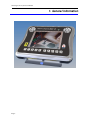
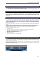
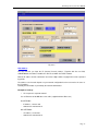
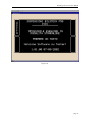
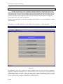
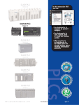
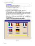
SD3 DIAGNOSTICS SYSTEM
USER MANUAL
SD3 Diagnostics System User Manual
Contents
PRECAUTIONS AND SAFETY MEASURES.................................................................................................... 4
Dataplate and warranty...................................................................................................................................... 5
Warranty ..................................................................................................................................................... 5
1. General information ....................................................................................................................................... 6
1.1 Minimum system requirements ................................................................................................................ 7
1.2 Suitcase contents..................................................................................................................................... 7
1.3 SD3 diagnostics system presentation...................................................................................................... 8
1.4 Power supply voltage ............................................................................................................................... 9
1.5 Installation instructions for the SD3 ......................................................................................................... 9
1.6 General Description ................................................................................................................................. 9
1.7 Self test .................................................................................................................................................... 9
1.8 Installing the Basic SD3NET software on the PC ................................................................................. 11
1.9 USB Driver ............................................................................................................................................. 11
2. SD3 Operation ............................................................................................................................................. 12
2.1 Start Screen ........................................................................................................................................... 13
2.2 Main Menu ............................................................................................................................................. 14
2.3 SD3 System HW/SW Information Menu ................................................................................................ 15
2.4 SD3 Configuration Menu........................................................................................................................ 16
2.5 Start PC Communications Menu............................................................................................................ 21
2.6 Start SD2 Emulator Communications Menu .......................................................................................... 23
2.7 Tools Selection Menu............................................................................................................................. 25
2.7.2 Data deleting ................................................................................................................................... 27
2.8 Expansions Menu................................................................................................................................... 28
2.9 OBD SCANTOOL SCREEN .................................................................................................................. 28
2.10 Check Versions .................................................................................................................................... 37
2.11 Serial Diagnostics Menu ...................................................................................................................... 38
2.12 Resolving SD3 Tester-related problems .............................................................................................. 44
3. SD3 Diagnostics Software ........................................................................................................................... 45
3.1 SD3 Diagnostics Software Operation .................................................................................................... 46
3.1.1 Main Menu .......................................................................................................................................... 46
3.1.2 Error menu .......................................................................................................................................... 47
3.1.3 Parameters menu................................................................................................................................ 52
3.1.4 Diagnostics Menu................................................................................................................................ 55
3.1.5 Acquisition Menu................................................................................................................................. 56
3.1.6 Information .......................................................................................................................................... 59
4. BASIC SD3NET PC Software .................................................................................................................... 60
4.1 Introduction ............................................................................................................................................ 61
4.2 Update Menu.......................................................................................................................................... 62
4.2.1 Update ECU Software ..................................................................................................................... 63
4.2.2 PC Update ....................................................................................................................................... 64
4.2.3 Exit................................................................................................................................................... 64
4.3 PC Communication Menu ...................................................................................................................... 65
4.3.1 Running the software on the PC ..................................................................................................... 66
4.3.2 SD3 Tester Settings ........................................................................................................................ 69
4.4 Tester Data Menu .................................................................................................................................. 70
4.4.1 Print Menu ....................................................................................................................................... 70
4.4.2 Acquisition Menu ............................................................................................................................. 72
4.4.3 Print file and acquisition file management. ......................................................................................... 83
4.5 Maintenance Menu................................................................................................................................. 83
4.5.1 Set Communications parameters .................................................................................................... 84
4.5.2 Workshop data ................................................................................................................................ 85
4.5.3 Vehicle data..................................................................................................................................... 86
4.5.4 Vehicle Database ............................................................................................................................ 87
4.5.5 Select Language ............................................................................................................................. 88
4.5.6 Transfer Operating System ............................................................................................................. 89
4.6 Information Menu ................................................................................................................................... 90
5. Problem solving ........................................................................................................................................... 91
5.1 The screen remains yellow when the tester is switched on................................................................... 92
5.2 The communication through serial line does not work........................................................................... 92
5.3 The communication by network cable does not work............................................................................ 92
Page 2
SD3 Diagnostics System User Manual
5.3.1 Tester joint to a local net. ................................................................................................................ 92
5.3.2 Tester directly joint to the PC. ......................................................................................................... 92
5.3.3 General problems ............................................................................................................................ 92
5.4 The wireless communication does not work properly. ........................................................................... 93
5.4.1 Tester connected to an access point .............................................................................................. 93
5.4.2 Tester connected in point-point mode ............................................................................................. 93
5.4.3 General problems ............................................................................................................................ 93
5.5 The USB communication does not work properly.................................................................................. 93
5.6 When the tester is switched on it displays a screen: “WAIT SOFTWARE DOWNLOAD”..................... 94
5.7 When the tester is switched on it blocks; the yellow screen to restore it does not appear................... 94
5.8 When the tester is switched on, it shows the unblock environment. ..................................................... 94
5.9 No tester in LAN available within the “Communication selection” environment. ................................... 94
6. PC Diagnostics Software............................................................................................................................. 95
6.1 Diagnostics Software Operation ............................................................................................................ 96
6.1.1 PC Error Menu .................................................................................................................................... 98
6.1.2 PC Parameter Menu ......................................................................................................................... 100
6.1.3 Cycle menu: ...................................................................................................................................... 101
6.1.4 Acquisition Menu............................................................................................................................... 103
7. Cabling....................................................................................................................................................... 106
7.1 Description of the Cabling.................................................................................................................... 107
8. Notes.......................................................................................................................................................... 113
Page 3
SD3 Diagnostics System User Manual
PRECAUTIONS AND SAFETY MEASURES
Before connecting and starting up the SD3 diagnostics system, you must study the operating
instructions carefully, especially the safety warnings. This will eliminate any doubt about how the Tester is
used from the very outset. It will prevent you from running the risk of personal injury or damaging the unit.
The device is not user serviceable. All repair procedures must be carried out by qualified personnel only.
Precautions against personal injury
Use a suitable power cord. To eliminate the risk of fire, only use the supplied power cord or one specified
for use with the device.
Avoid electrical overload. To avoid the risk of injury and fire, do not supply any of the device's inputs with
more than the specified voltage.
Precautions against damage to the device
Use a suitable power voltage. Do not power the device with more than the specified voltage. Use only the
battery power cord or power supply feeder provided with the product.
Do not operate the device if it is malfunctioning. If the device is damaged, have it serviced by a qualified
service technician.
Page 4
SD3 Diagnostics System User Manual
Dataplate and warranty
The dataplate is located beneath the supporting platform and bears the manufacturer's trademark and the
model and serial number for the device.
Write down the serial number in the space below and quote it when asking for information about the device.
SD3
Serial n
o
---------------------------------
Warranty
FERRARI/MASERATI warranties the "SD3" diagnostics system for 24 (twenty-four) months from the date of
purchase indicated on the delivery note supplied by FERRARI/MASERATI.
During the warranty period, FERRARI/MASERATI will replace free of charge any parts with manufacturing or
material defects acknowledged by FERRARI/MASERATI.
The warranty does not cover accidental damage or damage incurred during shipping or due to incorrect use
of the device.
Service under warranty does not renew or prolong the period of validity of the warranty.
For any service requirements, contact:
Servizio Assistenza Tecnica FERRARI S.p.A. v. Abetone Inf.re 41053 Maranello (MO) ITALY
Servizio Assistenza Tecnica MASERATI S.p.A. 322, v. Ciro Menotti 41100 Modena ITALY
Page 5
SD3 Diagnostics System User Manual
1. General information
Page 6
SD3 Diagnostics System User Manual
1.1 Minimum system requirements
The PC where the basic SD3NET software and Diagnostics Software are to be installed should have the
following minimum system requirements:
Hardware:
• Pentium® processor (>800 MHz);
• 256 Mb RAM;
• Free space on Hard Disk: 850 Mb;
• SVGA 16-bit color video card, 1024x768, small font;
• Keyboard, mouse and color monitor;
• One free communication line of the following types.
o One RS232C serial port;
o One USB port.
o Ethernet 10/100 network card.
o Wireless connection.
• CDROM player;
Software:
• Microsoft® Windows® XP Home or Professional (suggested) (Service pack 1) or Windows 98 SE/ME
(Service Pack 1) or Microsoft® Windows® 2000 (Service pack 4)
• Internet Explorer® 6.0(Service pack 1).
1.2 Suitcase contents
The SD3 Diagnostic System is supplied with a suitcase containing:
• SD3 Tester;
• Serial cable for SD3/SD2 connection to PC (SD3-CBL01) [095970327];
• Multimeter cable (SD3-CBL02) [095970328];
• Power supply feeder (SD3-CBL05) [095970331];
• EOBD SD3 diagnosis cable (SD3-CBL06) [095970332];
• Diagnosis cable with SD2 bridle (SD3-CBL07) [095970333];
• Connection cable for feeding among SD2 and SD3 bridle (SD3-CBL08) [095970334];
• Cigar lighter socket feeder (SD3-CBL09) [095970335];
• ISO 1 extension (SD3-CBL10) [095970336];
• ISO 2 extension (SD3-CBL11) [095970337];
• SD2 B-CAN adapter (SD3-CBL12);
• USB cable [095970330];
• 10/100 Mbps Ethernet cross-over cable [095970329];
• SD3 wireless board;
• SD3 Manual [095970324];
• SD3 Quick Reference;
• Installation CD-ROM [095970326];
• 8 metal-point rods for Multimeter.
• PC USB/Wireless board
For further information about the cabling wires please refer to chapter 7.
Page 7
SD3 Diagnostics System User Manual
1.3 SD3 diagnostics system presentation
The SD3 Diagnostics System is an electronic device for the diagnostics of electronic control units
(ECU) installed in modern vehicles.
The SD3 diagnostics system is a palmtop device with a backlit color LCD display and a membrane keypad
with twenty keys; it is also equipped with:
• three standard RS232C serial lines;
• six standard ISO9141 / CARB / KEYWORD 2000 serial lines;
• two standard CAN serial lines
• multimeter in volts (up to 200 V d.c.) and Ohm (up to 1 Mohm)
It can be interfaced to a PC containing the software required to update the ECU diagnostics software through
one of the following lines:
• standard RS232C serial line,
• USB serial line
• Ethernet 10/100Mbit network
• Ethernet Wireless 802.11b network
For better efficiency and faster data transfer between the PC and the SD3 unit, we suggest you use the USB
line or an Ethernet/Wireless network for communications.
Warning, the SD3 Tester keypad can be used as remote control for the PC software for all
communications lines except the serial lines.
SD2 Emulator
The SD3 diagnostics system can be used with SD2 Diagnostics software in the emulator mode.
The latter must be transferred to the SD3 tester through the basic SD3NET software and using the special
SD2 Porting CD (Never use the old SD2 CD).
If you wish to run diagnostics in STANDALONE mode, follow the old SD2 instructions.
If, instead, you wish to run diagnostics using the SD2 software on the PC, you must first press the "START
SD2 EMULATOR COMMUNICATIONS" button on the SD3 tester.
Be careful because in this mode, the only communications line possible between the PC and the SD3
is the RS232C serial line.
Multimeter
The SD3 Diagnostics System has an integrated multimeter that can take measurements in Volts (up to 200
V dc) and Ohms (up to 1 Mohm). This function can be selected from the SD3 Tester main menu.
Scantool OBD
The SD3 Diagnostics System has an integrated Standard Scantool OBD software. This system makes it
possible to automatically check for systems able to support the service (engine, shift, ...). Once the control
unit has been identified by the software, you can check some parameters/errors supplied by the system
itself.
This function can be selected from the SD3 Tester main menu.
Page 8
SD3 Diagnostics System User Manual
1.4 Power supply voltage
The SD3 requires a voltage between 8 and 16 V DC which is supplied either by the battery of the
vehicle being tested or by the power supply provided with the product.
1.5 Installation instructions for the SD3
The SD3 does not require any installation; it only needs to be configured with the diagnostics
software to be used. The downloaded software are stored in the non-volatile memory of the SD3 unit. The
SD3 is equipped with a battery-powered clock which can be set and checked on the PC through a special
software menu.
1.6 General Description
The figures below provide a diagram of the upper part (containing the power supply and diagnostics
connectors), front part of the SD3 unit (containing the display, keypad and ON light) and the lower part
(containing a flap which provides access to the connectors used to hook up an American PS2 keyboard for
the PC, and two PCMCIA connectors used for any hardware expansions-e.g. flash expansions, Wireless
card-through external boxes).
The ten keys at the bottom of the screen are used to input data (numbers/letters) into the diagnostics
software.
The directional arrows and the TAB key feature function repetition if the key is held down continuously.
In all menus, hold down "Switch" and "Esc" for 4 seconds to reset the SD3 Tester software. This speeds up
restarting the device if the software crashes (the Tester does not respond to keypad commands).
The top holds the following (see fig. 1.6.1):
• The power button.
• One 25-pin connector for power and serial diagnostics lines (on the power button side);
• One 9-pin connector (male) for hook up to the PC (in the centre);
• One 9-pin connector (female) for Multimeter inlet.
• One Ethernet 10/100 Mbit connector.
• One USB connector.
• One Connector to hook up a CRT VGA monitor
1.7 Self test
To quickly check that the device is functional, connect the power supply (for example, with the cord
and the mains power supply), press the power button and check that the led lights up. Within 20/30 seconds
the start icon appears on the display.
The SD3 has a resettable fuse. If it is activated because of an internal fault or due to the external cabling,
wait a few minutes to allow it to reset. If, when you switch on the SD3, the display does not light up, wait a
few minutes and repeat the procedure.
Fig. 1.7.1
Page 9
SD3 Diagnostics System User Manual
Fig. 1.7.2
Fig. 1.7.3
Page 10
SD3 Diagnostics System User Manual
1.8 Installing the Basic SD3NET software on the PC
Always check the minimum system requirements.
To install the Basic SD3NET software on the PC, proceed as follows:
1. Power up the PC where the program has to be installed;
2. Insert the program CD supplied with the SD3 in the CD drive.
3. If the user has enabled the AUTORUN function on the CD drive, the installation wizard will launch
automatically; in this case go to point 7, otherwise continue the procedure below;
4. Using your mouse, double-click on MY COMPUTER;
5. When the computer resources window opens, double-click on the CD icon where the SD3NET program
has been inserted;
6. Double-clicking opens a window showing the contents of the CD. Double click on SETUP.EXE. The
installation wizard will now run;
7. A window will be displayed for the selection of the language to use during the program installing.
8. The installation wizard displays a start window. Click on NEXT to continue;
9. You will be prompted to install Microsoft Framework NET 1.1 (if it is not present). Always confirm and
proceed with installation;
10. You are asked to name the directory in which the program will be installed (we recommend leaving the
default setting). Click on NEXT to continue;
11. You are asked to name the directory DATA in which the program will be installed (we recommend
leaving the default setting). Click on NEXT to continue;
12. The last window gives a summary of the previous selections. Press NEXT and the system starts copying
the program to your PC.
13. When the installation has terminated you will be asked to reboot your PC. This is essential for the
program to operate correctly;
14. When the PC has been rebooted, the SD3NET icon will appear on the desktop.
1.9 USB Driver
1. Insert the USB Adapter
2. Respond to the prompts as they appear.If you are prompted for the drivers, enter d:\ where d: is the
location of the CD-ROM drive where the Installation CD is inserted.
3. During the installation process, you may receive prompts for the Windows installation CD. Insert the
CD for your Windows operating system and indicate the correct path. Your computer goes through a
brief installation process during which it displays several windows indicating what is currently
installing.
Page 11
SD3 Diagnostics System User Manual
2. SD3 Operation
Page 12
SD3 Diagnostics System User Manual
2.1 Start Screen
When the SD3 is switched on, an introductory screen appears (see fig. 2.1.0) displaying the
FERRARI/MASERATI logo; this will remain on the display for a few seconds or until you press "ESC".
Fig. 2.1.0
If no keys are pressed for several minutes the SD3 goes into energy saving mode turning off the display
light; when the unit is in this mode, just touch any key to simply switch on the display again. Remember, the
continuous scrolling feature is implemented for the directional arrows and tab key feature; hold one of these
down to scroll through the list of options (the cursor cycles back to the beginning when the end of the column
or row is reached); to prevent accidentally accessing other menus, the other keys do not have this feature.
The start screen is shown in fig. 2.1.0
Page 13
SD3 Diagnostics System User Manual
2.2 Main Menu
Pressing "Enter" or "Esc" in the start screen, calls up the Main menu (see fig. 2.2.1).
The Main Menu provides access to the pages where you can configure the SD3, connect the PC for updates,
and where you can select and run the diagnostics programs.
To choose one of the options, just highlight it with the up/down arrows and/or Tab key and press "Enter". In
this screen the "Esc" key is not used since there are no higher level screens. At page bottom, the number of
subscription days left will be displayed.
Fig. 2.2.1
Page 14
SD3 Diagnostics System User Manual
2.3 SD3 System HW/SW Information Menu
Select "INFORMATION" to open a window (see fig. 2.3.1) displaying the version of the basic SD3
operating software, the amount of space available in the Tester's non-volatile memory (Free Space on Disk)
and the Serial Number of the Tester (which is also marked on the dataplate on the back of the device under
the supporting platform). Press "Enter" to return to the Main Menu.
You can print the displayed information by pressing "Enter" on the print icon.
Fig. 2.3.1
Page 15
SD3 Diagnostics System User Manual
2.4 SD3 Configuration Menu
Select SD3 configuration to activate the menu where you can select from the possible Tester
configurations (Fig. 2.4.1).
Fig. 2.4.1
Press "Communications" to select the parameters for the communications line between the PC and
the SD3 Tester. (fig.2.4.2)
SD3 Tester - PC communications line
On the left side of the screen you can select the SD3 Tester - PC communications line.
The following choices are available:
• USB line,
• Serial RS232 line;
• Ethernet 10/100 Mbit,/Wireless line.
Press one of the three buttons to select the desired communications line. It will only become
effective after you have pressed "CONFIRM".
Remember the selection must also be made on the Basic SD3NET software of the PC that will
be connected to the SD3.
On the right side of the screen you can select all addresses configuring the use of the Ethernet IP
LAN/SUBNET MASK network (fig. 2.4.2).
Page 16
SD3 Diagnostics System User Manual
Fig. 2.4.2
LAN Address
The first field lets you input the IP (Internet Protocol) address. Together with the next field,
SUBNETMASK, this address identifies the SD3 Tester within the TCP/IP network.
Both the IP address and the subnetmask are 32 bit, 4-digit numbers ranging from 0 to 255 separated
by periods.
The address to be inserted depends on your network configuration but it must never be the same as
the PC address.
Normally this information is provided by the network administrator.
Examples of settings
•
PC not part of a corporate network
Use an Ethernet 10/100 Mbit Crossover cable (supplied with the SD3 tester)
PC SETTINGS:
-
IP Address: 172.28.2.100
Subnetmask: 255.255.255.0
SD3 SETTINGS:
-
IP Address: 172.28.2.36
Subnetmask: 255.255.255.0
Page 17
SD3 Diagnostics System User Manual
•
PC within a corporate network
Use an Ethernet 10/100 Mbit network card (not supplied with the SD3 tester)
PC SETTINGS:
-
IP Address: (depends on the network administrator).
Subnetmask: (depends on the network administrator).
SD3 SETTINGS:
-
IP Address: (have the network administrator provide a static IP address).
Subnetmask: (get this information from the network administrator).
For problems related to the net configuration, refer to chapter 5 or contact the net installer.
Wireless Address
This field lets you in put an IP (Internet Protocol) Address. Together with the following field,
SUBNETMASK, this address identifies the SD3 Tester within the TCP/IP network using a Wireless
network.
Remember that this field is only displayed and valid if the card has been inserted in the SD3
Tester.
Both the IP address and the subnetmask are 32 bit, 4-digit numbers ranging from 0 to 255 separated
by periods.
The address to be inserted depends on your network configuration but it must never be the same as
the PC address.
Normally this information is provided by the network administrator.
The last choice for the Wireless network is the name of the access Point. For this configuration, see
the access Point manual.
The Wireless address must be different from the Ethernet line IP address (they must be on
different subnetworks, e.g. LAN 192.28.2.50, Wireless 172.28.2.50).
Examples of settings
See Ethernet 10/100 Mbit line selection.
ACCESS POINT/POINT-POINT SELECTION
The Wireless Net can work either in:
Access POINT mode
that means the SD3 Tester is connected via radio to an “Access Point” device that joins it to a wider
Lan Net (that is, formed by several devices/PC).
or in
POINT-POINT mode
That means the SD3 Tester is connected via radio directly to one PC and not to a wider PC Net.
ADVANCED
It allows to configure the data protection (WEP) on the Wireless transmission (40 bit or 104 bit
protection). By selecting one of the two entries it will be possible to choose a key (5 characters for
the 40 bit protection and 14 characters for the 104bit protection).
This key must be set within the operating system of the wireless PC.
IMPORTANT NOTE
“l”, “m”, “L” or “M” characters must not be present in the key.
Page 18
SD3 Diagnostics System User Manual
SD3NET PC IP Address for Direct Printing
In menus that permit data printouts (errors, parameters, information, ...), it is possible to send this
information directly to the PC printer using the SD3 tester under the following conditions:
• The communications line between the SD3 tester and the PC must be an Ethernet or
Wireless line
• The basic SD3NET software must be active on the SD3NET PC
To identify the PC containing the SD3NET system, you must select its IP address.
The IP address is a 32 bit, 4-digit number between 0 and 255 separated by periods. This information
can be obtained either by asking the network administrator or by following the procedure below:
• From the PC, press the START button at the bottom left
• Select RUN
• For Windows XP, 2000, NT type in CMD and click OK; for Windows 98, ME type in
command
• Input IPCONFIG and press ENTER
• The IP address is the address following the words IP Address :.......:172.28.3.3 (for example)
GATEWAY LAN
It is possible to select an IP address to perform the tcp/ip packets gateway.
PORT LAN PC
It is possible to select the gate relevant to the TCP/IP address to the PC.
Warning
This value (50000) must not be changed presently; it will be used for future new versions of
SD3NETPC.
Page 19
SD3 Diagnostics System User Manual
Select the USB line
Select the RS232 line
Once you have selected the line, just connect the cable.
If the line selected is RS232: RS232 PC cable (see chapter 7). The communication can be extremely
slow and one could not be able to use some systems).
If the line selected is USB: USB cable (see chapter 7).
If the connection is via LAN (recommended): cross-over cable (see chapter 7).
No cable needed in case of wireless connection.
Press "Language" to modify the language used in the SD3NET screens.(fig 2.4.1).
Press the button just below the language flag to confirm your choice and automatically exit the
window. To void without saving, press "Esc" or press the cancel key.
The language selected on the SD3 only affects the messages for the routine software which selects
and runs the diagnostics programs (basic SD3NET software). The diagnostics software language,
on the other hand, is selected in the PC initialization software; to avoid any possible inconsistencies,
make certain that the PC and SD3 are both using the same language.
Press "Esc" to return to the previous menu.
WARNING. TO SAVE TESTER DISK SPACE, THE DIAGNOSTICS SOFTWARE IS ONLY
DOWNLOADED IN ONE LANGUAGE (DEPENDING ON THE BASIC SD3NET SOFTWARE
SETTINGS ON THE PC).
TO SET THIS SOFTWARE TO ANOTHER LANGUAGE, YOU MUST SELECT THE DESIRED
LANGUAGE ON THE PC AND THEN UPDATE THE TESTER LANGUAGE.
Fig. 2.4.3
Page 20
SD3 Diagnostics System User Manual
2.5 Start PC Communications Menu
The START PC COMMUNICATIONS menu enables dialogue with the PC software to update
diagnostics programs and to download the acquisition files from the Tester to the PC. Select "START PC
COMMUNICATIONS" and press "Enter" to open the Menu shown in fig. 2.5.1.
The information that appears in the window depends on the communications mode selected.
Serial RS232 mode
A LED goes on and blinks as long as the unit is in communication with the PC.
Ethernet/Wireless mode
As soon as the PC software (Basic SD3NET software and/or control unit diagnostics software) activates a
connection with the SD3 Tester, the IP address of the user or users connected to the Tester is displayed in
the window.
In addition, a LED goes on and blinks as long as the unit is in communication with the PC (except when files
are being transferred).
As soon as the PC software is disconnected from the SD3 Tester, it disappears from the screen.
USB mode
A LED goes on and blinks as long as the unit is in communication with the PC.
Press "Esc" to return to the Main Menu.
Do not press "Esc" on the Tester while data is being exchanged with the PC as this would interrupt
the communications in progress.
Page 21
SD3 Diagnostics System User Manual
Fig. 2.5.1
Page 22
SD3 Diagnostics System User Manual
2.6 Start SD2 Emulator Communications Menu
Select "START SD2 EMULATOR COMMUNICATIONS" and press "ENTER" to open the screen
shown in fig. 2.6.2, that will upload the modules necessary to the SD2 emulator.
At the end of the upload (it could last a while, depending on how many SD1/SD2 ECU are installed) the
window 2.6.1. will be shown.
This menu enables dialogue with the diagnostics software on the PC developed for the SD2 (the SD1
software transferred on the SD2 as well).
You can use the SD3 Tester as though it were an SD2 Tester. Do not hook up to the vehicle using the EOBD
wiring (SD3-CBL06) supplied for new vehicles, rather use a harness (like the SD2 SD3-CBL07) to be
connected to the EOBD wiring that the shop already owns.
As for the SD2 tester, in this operating mode it is possible use the SD3 keypad to control the SD2 PC
software.
WARNING:
This menu uses a serial RS232 communications line (USB or LAN/WIRELESS lines cannot be
used). The various Basic SD3NET software packages will automatically set this serial line; upon
exiting, the previously set communications line for normal operations is automatically restored.
Do not use basic SD2 software to update the SD3 tester
The basic SD3NET PC software can update the SD2 diagnostics system software.
Warning: on some systems, to use the RS232 serial line can cause problems of connection.
Press “Esc” to return to the Main Menu.
Do not press "Esc" on the Tester while data is being exchanged with the PC as this would interrupt
the communications in progress.
fig. 2.6.1
Page 23
SD3 Diagnostics System User Manual
Fig. 2.6.2
Page 24
SD3 Diagnostics System User Manual
2.7 Tools Selection Menu
The TOOLS SELECTION lets you use the tools (available on the SD3 such as the Multimeter).
Select TOOLS SELECTION and press "Enter" to display the menu shown in fig. 2.7.1. To choose one of the
options, just highlight it with the up/down arrows or tab key and press "Enter". Press “Esc” to return to the
Main Menu.
Fig. 2.7.1
2.7.1 Multimeter Menu
The Multimeter menu permits use of a Voltmeter and Ohmmeter integrated with the Tester. Select
"MULTIMETER" and press "Enter" to display the Menu shown in fig. 2.8.1.
Page 25
SD3 Diagnostics System User Manual
Fig. 2.8.1
The Voltmeter operates in the range +/-200V dc (4 auto-range scales) with a precision of 0.5% of the full
scale.
The Ohmmeter operates in the range 0..1 MOhm (4 auto-range scales) with a precision of 0.5% of the full
scale.
To use the Multimeter, attach the SD3 tester cable to the 9-pin connector. The red (+) and black (-) pins are
used by the Voltmeter and the blue pins are used by the Ohmmeter.
Press "Esc" to return to the Tools Selection Menu.
Page 26
SD3 Diagnostics System User Manual
2.7.2 Data deleting
The Data Deleting environment allows deleting the data on the Tester and to free space on the disk.
When the tester is switched on the data deleting environment shows a second submenu, just like in figure
2.7.2.1.
Fig.2.7.2.1.
Selecting DELETE ALL DIAGNOSIS SW, one will delete from tester all the diagnosis sw previously
downloaded. This means, it will not be possible to execute them newly and in case of use it will be necessary
to download them again.
Selecting DELETE ALL ACQUISITIONS, one will delete from tester’s disk all the present acquisitions.
Selecting DELETE ALL PRINTS, one will delete from tester’s disk all the prints.
After choosing one of the present entries, the screen of the figure 2.7.2.2 will be displayed.
Page 27
SD3 Diagnostics System User Manual
Fig. 2.7.2.2
By pressing YES the deleting will be definitive and irreversible, pressing NO one will return back to the
previous menu.
2.8 Expansions Menu
The Expansions Menu makes it possible to run non-diagnostics programs for the ECUs downloaded
from the PC (for example: oscilloscope, ...). Select "EXPANSIONS" and press "Enter" to display the list of
programs preloaded into the Tester. If no programs are loaded into the Tester.
Press "Enter" or "Esc" to return to the Tools Selection Menu.
2.9 OBD SCANTOOL SCREEN
From the main diagnostics sw menu, select "OBD SCANTOOL" to enter the OBD (On Board
Diagnostic) menu. This software serves for diagnosis of vehicle systems that implement the Scantool
protocol; that is the diagnostics protocol controlling the vehicle's pollution emissions. No selection is planned
since the software communicates with all control units in the vehicle that support the protocol.
Press "enter" to immediately load the diagnostics software (indicated by a red bar). Once it has
loaded, a window prompts you to turn the key to "ON" and press confirm to initialize the system (see figure
2.9.1). If there is no dialogue with the vehicle, a message prompts you to check the connection between the
tester and the control unit. If the initialization process is completed successfully, a list of the control units
initialized appears (typically engine and clutch). The individual ECUs are identified through the protocol
wake-up address, its only characterizing element (see fig. 2.9.2).
Press "enter" to call up the main menu in fig. 2.9.3
The diagnostics functions are characterized by a number (ex. $01 service).
Page 28
SD3 Diagnostics System User Manual
For all menus except the errors screen, pressing "enter" at this level calls up a screen with a list of
the ECUs that have been initialized. This makes it possible to filter the system responses; that is to display
the parameters for that given ECU.
Fig. 2.9.1
Page 29
SD3 Diagnostics System User Manual
Fig. 2.9.2
Page 30
SD3 Diagnostics System User Manual
Fig. 2.9.3
Service $01- Parameters
In this menu, all dynamic parameters (requested continuously) supported by the previously selected ECU,
and only these, are displayed. To move through the windows, use the SD3 tester keys following the rules
indicated above in the paragraph on serial diagnostics. See fig. 2.9.4.
Page 31
SD3 Diagnostics System User Manual
Fig. 2.9.4
Page 32
SD3 Diagnostics System User Manual
Service $02 - FFD
In this menu, the Freeze-Frame-Data are displayed (if present). These are the parameters that delimit an
error (present or saved at that moment in the ECU) that the ECU saved when the problem occurred. The
error is reported on the first line of the screen as P-CODE. If there are no errors, or if no data has been
saved, a special dialog box provides this information and invites you to continue. To move through the
windows, use the SD3 tester keys following the rules indicated above in the paragraph on serial diagnostics.
See fig. 2.9.5
Fig. 2.9.5
Service $03 - Errors
This menu does not present a previously selected ECU, as mentioned above. In fact, all errors present in all
currently active ECUs are reported as P-CODE (that is standardized alphanumeric code). The particular
node containing the error is indicated by displaying the address of the ECU itself, next to the error code. If a
given DTC (Diagnostic Trouble Code) is present on more than one ECU, all the addresses are displayed. To
move through the windows, use the SD3 tester keys following the rules indicated above in the
paragraph on serial diagnostics. See fig. 2.9.6
Page 33
SD3 Diagnostics System User Manual
Fig. 2.9.6
Service $04 - Deleting errors
Contrary to serial diagnostics, deleting errors has its own particular menu since it implements a precise
service (service 4) of the OBD protocol. Here, too, the ECU is not preselected. Rather error deletion always
refers to ALL currently active systems. The OBD protocol requires that deletion be performed only when the
engine is off: a dialog box message reminds you of this fact. The outcome of the operation is indicated after
the command is issued. See fig. 2.9.7.
Page 34
SD3 Diagnostics System User Manual
Fig. 2.9.7
Service $09 - Info
In this menu, some information regarding the specific ECU (message counter, VIN, ... if supported) are
displayed as though they were dynamic parameters. To move through the windows, use the SD3 tester keys
following the rules indicated above in the paragraph on serial diagnostics. See fig. 2.9.8
Page 35
SD3 Diagnostics System User Manual
Fig. 2.9.8
Page 36
SD3 Diagnostics System User Manual
2.10 Check Versions
The CHECK VERSIONS menu lets you display the versions of the diagnostics software installed on
the SD3 tester in the following format (fig 2.10.1)
MANUFACTURER
FERRARI
Model
F137
system
Version
NBC Body Computer 090000 1.00
Date
21 11 2003
Release
6.2
Press the button with the printed icon to print these data.
Press “Esc” to return to the Main Menu.
Fig. 2.10.1
Page 37
SD3 Diagnostics System User Manual
2.11 Serial Diagnostics Menu
The Serial Diagnostics Menu lets you run the ECU diagnostics programs loaded into either the SD3
or SD2 from the PC. Select "DIAGNOSTICS" and press "Enter" to display the list of diagnostics programs
pre-loaded into the Tester; if no programs have been pre-loaded, the device will display fig. 2.11.1.
Fig. 2.11.1
Press "Enter" or "Esc" to return to the Main Menu.
If the device contains diagnostics programs, you will be guided through selection of the diagnostics you wish
to run. To select a diagnostics program, you are almost always required to specify the Manufacturer of the
vehicle in which the ECU is installed, the vehicle and ECU model, and finally the system to be tested. If more
than one serial line is available for the diagnostics routine, you will be prompted to specify which one to use.
This is not normally the case because the SD3 automatically selects the default line set during vehicle
design. Therefore the last passage is hidden to the user (on the contrary, if you have selected diagnostics of
the previous SD2 system, the procedure requires you to set the diagnostics line as well).
The procedure thus starts with selection of the Manufacturer (from among the diagnostics programs loaded
into Tester). The display can appear as shown in fig. 2.11.2.
Page 38
SD3 Diagnostics System User Manual
Fig. 2.12.2
Select the Manufacturer with the arrow keys and press "Enter" to confirm. You can flip through the pages by
pressing key "8" (previous page) and "9" (next page) or, if the unit is connected to an outside keypad, by
pressing PGUP and PGDN.
Press "Esc" to return to the Main menu. If, for instance, we select FERRARI and press "Enter", a page
similar to the one shown in fig. 2.12.3 will be displayed.
Page 39
SD3 Diagnostics System User Manual
Fig. 2.12.3
For this window, the above rules apply. At the bottom of the window appears a field which displays the
previous selection (FERRARI). If we select F137 and press "Enter", a page similar to the one shown in
fig.2.11.4 will be displayed.
Page 40
SD3 Diagnostics System User Manual
Fig. 2.11.4
For this window, the rules given above for selecting the Manufacturer apply. At the bottom of the window
appears a field which displays the previous selection (FERRARI F137). If we select NBC (Body computer)
MARELLI and press "Enter" we enter the serial line selection screen or the diagnostics software. Let us
assume that we do not need to select the serial line (this is rarely necessary and in any case follows the
same procedure outlined in the points already covered). After having made all the required selections, the
tester will automatically request the vehicle serial code to the ECU. Then we enter the diagnostics software.
Note: the vehicle serial code request will not be repeated until the user will not quit the ECU/SYSTEM
selection window.
Loading the software required for diagnostics of the selected program is accompanied by a red bar indicating
the progress.
Page 41
SD3 Diagnostics System User Manual
Fig. 2.11.5
If an error screen appears during the diagnostics software selection phase, the diagnostics software that
caused the load/run problems must be reinstalled through the PC software.
If the selected software was an SD2 emulator, you will be prompted for the communications line, prompted to
input the special SD2 harness (SD3-CBL07), and finally the software will be run presenting the same SD2
graph. (For a description of software operation, see the SD2 user's manual contained in the SD3Net CD in
the 5 languages under the ManualSD2 directory). (Fig.2.11.6)
Be aware of whether you are connected to an EOBD outlet (SD3-CBL06). In this case, you must turn off the
SD3 Tester, connect the special SD2 harness (SD3-CBL07) and then start the ECU selection process over
again.
Once you have completed the activity with this SD2 emulation diagnostics program, SD3 will be
automatically reset.
Page 42
SD3 Diagnostics System User Manual
Fig. 2.11.6
Page 43
SD3 Diagnostics System User Manual
2.12 Resolving SD3 Tester-related problems
checks:
After having turned on the SD3 Tester, if nothing is displayed on the screen, run the following
-
Check that the Green light on the upper part of the Tester is on;
If this light is off, check that the EOBD plug has been inserted into the vehicle correctly or, if
it is a 110/220 Volt network connection, check whether the outside power supply is
connected properly;
If the light is on, wait 60 seconds and then try to reboot.
If the SD3 Tester still does not go on, but the light is on, reboot the tester by pressing KEYS "1" and "2" on
the numeric keypad simultaneously and keeping them pressed for 20 seconds.
If the words:
"WAIT FOR SOFTWARE DOWNLOAD"
appear on the screen, download the Basic SD3NET PC program Operating System and then install the
Basic SD3 SOFTWARE from the Update ECU SW screen.
REMEMBER, IN PERFORMING THIS TYPE OF UPDATING, YOU CAN ONLY USE THE SERIAL OR USB
LINES FOR COMMUNICATIONS BETWEEN THE PC AND THE SD3 TESTER
Should one be unable to sort out these problems, please contact the After Market Service.
Page 44
SD3 Diagnostics System User Manual
3. SD3 Diagnostics Software
Page 45
SD3 Diagnostics System User Manual
3.1 SD3 Diagnostics Software Operation
The SD3 tester makes it possible to distribute and update diagnostics software developed as new
vehicles are released. Each diagnostics software will be different from all others depending on the particular
ECU it tests and also the version of the software being used. The following operational description covers the
standard diagnostics menu (for a ECU developed in parallel with the SD3 itself), and serves to give general
indications on how the various diagnostics menus perform; it should be understood that each diagnostics
program will have its own specific documentation.
After the screen shown in fig. 2.12.5, which may display for half a minute or so, the real diagnostics software
starts execution.
If execution is successfully completed, a screen similar to the one in fig.3.1.1.1 will be displayed.
3.1.1 Main Menu
Fig. 3.1.1.1
The diagnostics main menu contains the various available menus (in this case Errors, Parameters,
Diagnostics, Acquisition, Information, Exit ); Select the menus in the same way as for all other screens
(select with the arrows or tab keys, "Enter" to confirm, "Esc" to return to the previous menu). From the
program's main menu, press "Esc" or select "Exit" and confirm to return to the ECU selection screen. At the
top, the current selection is displayed (FERRARI F137 NBC MARELLI).
Page 46
SD3 Diagnostics System User Manual
3.1.2 Error menu
Select Errors and press "Enter" to go to an menu in which the Tester continuously prompts the ECU for any
errors stored in its memory. It then displays the errors status (No Error or the list of errors encountered). If
there are any errors in the ECU's memory, the screen will be similar to the one shown in fig. 3.1.2.1. The bar
above the errors is yellow if the ECU is connected and diagnostics are running, and is red if the link between
the ECU and the Tester fails. In the latter case a page similar to the one shown in fig. 3.1.2.2 is displayed
prompting you to check the connection and confirm your desire to attempt initialization again. Press "Enter"
to try again, or "Esc" to return to the screen shown in fig. 3.1.1.1. In the case shown in fig. 3.1.2.1, some
errors are displayed on a single page (PAGE 1/1 on the yellow bar).
If more than 11 errors are present, there will be more than one page. To scroll through the various pages,
use the up/down arrows or flip through the pages using key "8" PGUP or "9" PGDN.
Fig. 3.1.2.1
Page 47
SD3 Diagnostics System User Manual
Fig. 3.1.2.2
Press "Esc" to return to the screen shown in fig. 3.1.1.1.
Press tab to highlight the various errors one by one. After having highlighted a particular error, press "Enter"
to view any additional information regarding the problem. An example is given in figure 3.1.2.3.
Page 48
SD3 Diagnostics System User Manual
Fig. 3.1.2.3
Use the arrow keys to scroll lists of information. "Esc" returns to the Display Errors page (fig. 3.1.2.1).
In the screen shown in fig. 3.1.2.3, pressing the printer icon key writes on the Tester disk a file with the errors
encountered and all associated information. The screen which displays while the file is writing will look like
the one shown in fig. 3.1.2.4. These files can be transferred to the PC and printed out (see par. 4.4). The
Tester stores them in non-volatile memory (and hence they will stay in memory even after the Tester is
switched off). Nevertheless, to prevent wasting Tester disk space, it is best to periodically transfer the files to
the PC disk (through the special SD3NET PC menu) and delete them from the tester disk.
Page 49
SD3 Diagnostics System User Manual
Fig. 3.1.2.4
Press the DELETE icon to delete the errors from the ECU. The screen which appears is similar to the one
shown in fig. 3.1.2.5. At the end of the procedure, a window is displayed with the result of the delete as
returned by the ECU (Delete OK/Delete Failed).
Page 50
SD3 Diagnostics System User Manual
Fig. 3.1.2.5
Page 51
SD3 Diagnostics System User Manual
3.1.3 Parameters menu
Select Parameters menu and press "Enter" to go to the dynamic parameters page. The parameters are
usually displayed sorted into dimensional types, hence from the screen shown in fig. 3.1.1.1 the program
goes to a screen similar to the one shown in fig. 3.1.3.1.Select them as for all other menus (select using tab
and arrow keys, "Enter" to confirm, "Esc" to return to the previous menu).
Fig. 3.1.3.1
Select one of the options and press "Enter" to go to a menu in which the Tester continuously prompts the
ECU to determine the current value of the parameters. The screen will be similar to the one shown in fig.
3.1.3.2. The text is on a yellow background if the ECU is connected and diagnostics are running, and on a
red background if the link between the ECU and the Tester fails. In the latter case a page similar to the one
shown in fig. 3.1.2.2 is displayed prompting you to check the connection and confirm your desire to attempt
initialization again. Press "Enter" to try again, or "Esc" to return to the screen shown in fig. 3.1.3.1.
Page 52
SD3 Diagnostics System User Manual
Fig. 3.1.3.2
In the case shown in fig. 3.1.3.2 there are 11 parameters displayed on a single page (PAGE 1/1 on the
yellow bar). If there were more than 12 parameters there would be more than one page. To scroll through
these pages use the up/down arrows or flip through the pages using the number keys "8" PGUP and "9"
PGDN.
There are generally two types of parameters:
• Analogue parameters (such as engine rpm): the value of the parameter and its dimensions are
displayed.
• Digital parameters (such as Vehicle Control Status): the decoded value is shown in its actual meaning.
Pressing the print icon button writes on the Tester disk a file with the file name and the parameter values for
the selected menu. The screen which displays while the file is writing will look like the one shown in
fig. 3.1.3.3. These files can be transferred to the PC and printed out (see par. 4.4). The Tester stores them in
non-volatile memory (and hence they will stay in memory even after the Tester is switched off).
From the Parameters Menu in fig. 3.1.3.2, press "Esc" to return to the main diagnostics software menu
shown in fig. 3.1.3.1.
Page 53
SD3 Diagnostics System User Manual
Fig. 3.1.3.3
Page 54
SD3 Diagnostics System User Manual
3.1.4 Diagnostics Menu
Select the Active Diagnostics Menu and press "Enter" to send control signals to the ECU. The Active
Diagnostics menu is the one menu that could differ from one ECU to another; the one described here is only
one of the possible implementations. The active diagnostics screen will look something like the one in
fig. 3.1.4.1. The various active diagnostics are arranged in a menu. The various options are selected as in all
other menus (select using tab and arrow keys, "Enter" to confirm, "Esc" to return to the previous menu). To
exit from the help screen press "Enter" or "Esc".
Fig. 3.1.4.1
If we select a particular diagnostics and press "Enter" we enter a guided procedure which uses user prompts
and sends signals to the ECU to effect the desired implementations. If, for example, we need to switch off
the engine to run the command, a screen similar to the one in fig. 3.1.4.2 will be displayed. The requested
condition is displayed (Engine Status: Off), the parameter is constantly checked by the Tester (Engine rpm)
comparing the value requested and the value read. The condition must be maintained for a few seconds
before being deemed satisfactory and moving on to issuing the next command.
During this period, pressing "Esc" displays the menu shown in fig. 3.1.4.1.
Page 55
SD3 Diagnostics System User Manual
Fig. 3.1.4.2
When the condition has been satisfied, the Tester will send the actuation command to the ECU; in case of an
incorrect response from the ECU, an error window is displayed (Test Failed), otherwise a window is
displayed with the name of the test underway (fig. 3.18.12). You can interrupt the command by pressing
"Esc"; if this does not take place, the Tester will in any case interrupt the command after a set time. In both
cases, the Tester returns to the screen shown in fig. 3.1.4.1.
3.1.5 Acquisition Menu
From the main diagnostics sw menu, select "ACQUISITION MENU" to enter the menu where you can
acquire data (parameters and errors) constantly requested of the ECU. In particular, a submenu is displayed
offering the possible options: "ACQUISITION WITH DISPLAY", "ACQUISITION WITHOUT DISPLAY",
“ACQUISITION IN TEXTUAL MODE" (see figure 3.1.5.1).
Select one of the above menus and a screen appears. The left side of this screen presents a list of all
parameters implemented in the ECU and the right side shows a list of the errors. Use the arrows to scroll
through the data contained in the selected list, press "Tab" to move the item selected to the other list or
press confirm. When a parameter/error is pressed, pressing the "enter" key selects (or deselects if it was
already selected) the highlighted data. On the other hand, while if you press confirm, you move on to the
next menu typical of each acquisition mode. A counter at the foot of the page indicates the individual report
number_element_totals_selected/number_element_totals_selectable (even if the latter depends on the
selected data acquisition mode). Two smaller, initially empty lists echo the data you have selected reporting,
in particular, on the right the selected parameters and on the left the errors selected for acquisition (see
fig. 3.1.5.2). Selections not permitted (if, for example, the maximum number of elements has been exceeded)
is indicated in a special dialog box.
Page 56
SD3 Diagnostics System User Manual
Once you have selected all the elements you wish to acquire, press "enter" with the "confirm" button selected
and you can move on to the next screen.
Fig. 3.1.5.1
Page 57
SD3 Diagnostics System User Manual
Fig. 3.1.5.2
Acquisition with display
The screen displays the trend in time for the parameters selected in different graphs but which all share the
abscissa (time). Each graph displays the current value, unit of measure (if present), space on the grid both in
the direction of the abscissa (horizontal step) and ordinate (vertical step), graph limits (both for time and the
value taken on by the parameter).
Throughout the period the value is displayed, a file is created in the non volatile memory that can be handled
with a special PC sw menu. Press "Esc" to exit the graph menu and interrupt saving the data to file
Acquisition without display
Even though dialogue with the ECU is immediately active, to start acquisition to file you must select the
special button (START ACQUISITION) and press "enter". The counters in the yellow box will then begin
counting the value sampling moment and the progressive number of samples acquired. Press "END
ACQUISITION" to interrupt data acquisition to file and reset the counters. You can start the procedure again
by pressing "START ACQUISITION" once more. These keys can be selected either by using the arrow or
"Tab" keys. Press "Esc" to exit this menu (any acquisition in progress will be interrupted) and return to the
previous screen.
Acquisition in textual mode
For each parameter, this menu reports the current value read by the ECU and, if it is an analog value, it also
reports the minimum and maximum value for each constantly updated datum. For acquisition with display,
the data save begins automatically when you enter the menu and terminates when you press "Esc". At the
foot of the page, the number of samples acquired to that point is displayed along with the sampling instant
(expressed in milliseconds) which is updated constantly.
Page 58
SD3 Diagnostics System User Manual
3.1.6 Information
From the diagnostics software main menu in fig. 3.1.6.1, select the ECU Information menu and press "Enter"
to display information on the hardware and software versions of the ECU. The information displayed
depends on the particular ECU involved in the diagnostics; a possible implementation is shown in figure
3.1.6.1. The Diagnostics SW Version refers to the program running on the Tester, all the other information
refers to the ECU itself. In the screen shown in fig. 3.1.6.1, pressing the print icon writes on the Tester disk a
file containing the information displayed. These files can be transferred to the PC and printed out (see
par. 4.4). The Tester stores them in non-volatile memory (and hence they will stay in memory even after the
Tester is switched off).
Fig. 3.1.6.1.
Press "Esc" to return to the diagnostics software main menu in fig. 3.1.1.1; use the up/down arrows to scroll
through the information list.
Page 59