1
0801IP/1601IP
Installation and User
Guide
Based on Firmware 03.05.02
Last update: February 3, 2005
Document ID: p_1601ip_00en_manualv2
©Copyright 2003-2005 Peppercon AG
All rights reserved.
Scheringerstr. 1
08056 Zwickau (Saxony)
Germany
This publication contains proprietary information, which is protected by copyright. No part of
this publication may be reproduced, transcribed, stored in a retrieval system, translated into
any language or computer language, or transmitted in any form whatsoever without the prior
written consent of the publisher, Peppercon AG. Peppercon AG acknowledges the following
trademarks:
Intel is a registered trademark of Intel Corporation.
Windows 98, Microsoft Windows, and Windows NT are trademarks of Microsoft Corporation.
IBM, AT, VGA, PS/2, and OS/2 are registered trademarks and XT and CGA are trademarks of International Business Machines Corporation.
Peppercon is a registered trademark of Peppercon AG Zwickau, Germany.
Other trademarks and trade names may be used in this document to refer to either the entities
claiming the marks and names or their products. Peppercon AG disclaims any proprietary
interest in trademarks and trade names other than its own
Authors: Peppercon Team
This document was created on February 3, 2005.
ii
The 0801IP/1601IP (8/16-port KVM and KVMIP) provides server management capabilities.
You can use 0801IP/1601IP to manage and monitor components in your servers through a
modem, an ISDN line or LAN, even if your network is down(Modem/ISDN). 0801IP/1601IP
offers a comprehensive hardware solution to server management.
Limited Warranty
The buyer agrees that if this product proves to be defective, Peppercon AG is only obligated
to repair or replace this product at Peppercon AG’s discretion according to the terms and
conditions of the warranty registration card that accompanies this product. Peppercon AG
shall not be held liable for any loss, expenses or damage, direct, incidental or consequential
resulting from the use of this product. Please see the Warranty Information shipped with this
product for full warranty details.
Limitations of Liability
Peppercon AG shall in no event be held liable for any loss, expenses or damages of any kind
whatsoever, whether direct, indirect, incidental, or consequential (whether arising from the
design or use of this product or the support materials provided with the product). No action or
proceeding against Peppercon AG may be commenced more than two years after the delivery
of the product to the licensee of Licensed Software.
The licensee agrees to defend and indemnify Peppercon AG from any and all claims, suits, and
liabilities (including attorney’s fees) arising out of or resulting from any actual or alleged act or
omission on the part of Licensee, its authorized third parties, employees, or agents, in connection
with the distribution of Licensed Software to end-users, including, without limitation, claims,
suits, and liability for bodily or other injuries to end-users resulting from use of Licensee’s
product not caused solely by faults in Licensed Software as provided by Peppercon AG to
Licensee.
Technical Support
If you need help installing, configuring, or running 0801IP/1601IP, call your Peppercon OEM
or VAD Technical Support representative.
We invite you to access Peppercon’s Web site at:
http://www.peppercon.com/
There you shall find all modifications made after the editorial deadline.
iii
iv
Contents
1 The Quick Installation Guide
1
2 Introduction
2.1 When the server is up and running . . . . . . . . . . . . . . . . . . . . . . . . . .
2.2 When the server is dead . . . . . . . . . . . . . . . . . . . . . . . . . . . . . . . .
7
8
9
3 Installation
3.1 Operation Overview . . . . . . . . . .
3.2 Connectors and Jumpers . . . . . . . .
3.2.1 Front Side Connectors . . . . .
3.2.2 Rear Side Connectors . . . . .
3.3 Connecting 0801IP/1601IP to the host
3.3.1 Connecting the External Power
3.3.2 Connecting Ethernet . . . . . .
3.3.2.1 10 Mbps Connection .
3.3.2.2 100 Mbps Connection
. . . . . . . . .
. . . . . . . . .
. . . . . . . . .
. . . . . . . . .
system . . . . .
Switch Option
. . . . . . . . .
. . . . . . . . .
. . . . . . . . .
4 Configuration
4.1 Initial Configuration . . . . . . . . . . . . . . . .
4.1.1 Initial configuration via DHCP server . .
4.1.2 Initial configuration via serial interface . .
4.1.3 Mouse, Keyboard and Video configuration
4.1.3.1 0801IP/1601IP mouse settings .
4.1.3.2 Host system mouse settings . . .
4.1.3.3 0801IP/1601IP Video Modes . .
.
.
.
.
.
.
.
.
.
.
.
.
.
.
.
.
.
.
.
.
.
.
.
.
.
.
.
.
.
.
.
.
.
.
.
.
.
.
.
.
.
.
.
.
.
.
.
.
.
.
.
.
.
.
.
.
.
.
.
.
.
.
.
.
.
.
.
.
.
.
.
.
.
.
.
.
.
.
.
.
.
.
.
.
.
.
.
.
.
.
.
.
.
.
.
.
.
.
.
.
.
5 Usage
5.1 Prerequisites . . . . . . . . . . . . . . . . . . . . . . . . . . . .
5.2 Using 0801IP/1601IP as a KVM switch . . . . . . . . . . . . .
5.3 Login into 0801IP/1601IP and logout . . . . . . . . . . . . . . .
5.3.1 Login into 0801IP/1601IP . . . . . . . . . . . . . . . . .
5.3.2 Main Screen . . . . . . . . . . . . . . . . . . . . . . . . .
5.3.3 Logout from 0801IP/1601IP . . . . . . . . . . . . . . . .
5.4 Remote Console . . . . . . . . . . . . . . . . . . . . . . . . . . .
5.4.1 Show Remote Console . . . . . . . . . . . . . . . . . . .
5.4.1.1 Description of Remote Console Options . . . .
5.4.2 Remote Chat Frame . . . . . . . . . . . . . . . . . . . .
5.4.3 0801IP/1601IP Mouse Synchronization . . . . . . . . . .
5.4.3.1 Introduction . . . . . . . . . . . . . . . . . . .
5.4.3.2 Auto mouse speed and mouse synchronization
5.4.3.3 Limitations of the mouse synchronization . . .
.
.
.
.
.
.
.
.
.
.
.
.
.
.
.
.
.
.
.
.
.
.
.
.
.
.
.
.
.
.
.
.
.
.
.
.
.
.
.
.
.
.
.
.
.
.
.
.
.
.
.
.
.
.
.
.
.
.
.
.
.
.
.
.
.
.
.
.
.
.
.
.
.
.
.
.
.
.
.
.
.
.
.
.
.
.
.
.
.
.
.
.
.
.
.
.
.
.
.
.
.
.
.
.
.
.
.
.
.
.
.
.
.
.
.
.
.
.
.
.
.
.
.
.
.
.
.
.
.
.
.
.
.
.
.
.
.
.
.
.
.
.
.
.
.
.
.
.
.
.
.
.
.
.
.
.
.
.
.
.
.
.
.
.
.
.
.
.
.
.
.
.
.
.
.
.
.
.
.
.
.
.
.
.
.
.
.
.
.
.
.
.
.
.
.
.
.
.
.
.
.
.
.
.
.
.
.
.
.
.
.
.
.
.
.
.
.
.
.
.
.
.
.
.
.
.
.
.
.
.
.
.
.
.
.
.
.
.
.
.
.
.
.
.
.
.
.
.
.
.
.
.
.
.
.
.
.
.
.
.
.
.
.
.
.
.
.
.
.
.
.
.
.
.
.
.
.
.
.
11
11
11
11
12
12
13
13
13
14
.
.
.
.
.
.
.
15
15
15
15
17
17
17
17
.
.
.
.
.
.
.
.
.
.
.
.
.
.
19
19
20
24
24
25
26
26
26
28
29
31
31
31
32
vi
Contents
5.4.3.4 Single and Double Mouse Mode . . . . . . .
0801IP/1601IP Video Settings . . . . . . . . . . . . .
5.4.4.1 Video Settings through the HTML-Frontend
5.4.4.2 Video Settings through the remote console .
5.4.4.3 Custom Video Modes . . . . . . . . . . . . .
5.4.5 Remote Console Settings . . . . . . . . . . . . . . . .
5.4.6 Telnet Console . . . . . . . . . . . . . . . . . . . . . .
Server . . . . . . . . . . . . . . . . . . . . . . . . . . . . . . .
5.5.1 Power Control . . . . . . . . . . . . . . . . . . . . . .
5.5.1.1 External power option . . . . . . . . . . . .
5.5.1.2 Power Switch Status . . . . . . . . . . . . . .
5.5.2 Keyboard/Mouse Settings . . . . . . . . . . . . . . . .
5.5.3 KVM Settings . . . . . . . . . . . . . . . . . . . . . .
Administration . . . . . . . . . . . . . . . . . . . . . . . . . .
5.6.1 User/Group Management . . . . . . . . . . . . . . . .
5.6.1.1 Add User . . . . . . . . . . . . . . . . . . . .
5.6.1.2 Delete User . . . . . . . . . . . . . . . . . . .
5.6.1.3 Modify User . . . . . . . . . . . . . . . . . .
5.6.1.4 Copy User . . . . . . . . . . . . . . . . . . .
5.6.1.5 Add Group . . . . . . . . . . . . . . . . . . .
5.6.1.6 Delete Group . . . . . . . . . . . . . . . . . .
5.6.1.7 Modify Group . . . . . . . . . . . . . . . . .
5.6.1.8 Copy Group . . . . . . . . . . . . . . . . . .
5.6.2 User/Group Permissions . . . . . . . . . . . . . . . . .
5.6.3 Port Access Permissions . . . . . . . . . . . . . . . . .
5.6.4 Network Settings . . . . . . . . . . . . . . . . . . . . .
5.6.4.1 Dynamic DNS . . . . . . . . . . . . . . . . .
5.6.5 Serial Settings . . . . . . . . . . . . . . . . . . . . . .
5.6.6 External Power Options . . . . . . . . . . . . . . . . .
5.6.7 Modem Settings . . . . . . . . . . . . . . . . . . . . .
5.6.8 Authentication Settings . . . . . . . . . . . . . . . . .
5.6.8.1 LDAP . . . . . . . . . . . . . . . . . . . . . .
5.6.8.2 RADIUS . . . . . . . . . . . . . . . . . . . .
5.6.9 Security Settings . . . . . . . . . . . . . . . . . . . . .
5.6.9.1 SSL Settings . . . . . . . . . . . . . . . . . .
5.6.9.2 Telnet Settings . . . . . . . . . . . . . . . . .
5.6.9.3 IP Access Control . . . . . . . . . . . . . . .
5.6.9.4 Anti Brute Force Setting . . . . . . . . . . .
5.6.10 SSL Certificate Management . . . . . . . . . . . . . .
5.6.11 Maintenance . . . . . . . . . . . . . . . . . . . . . . .
5.6.11.1 Maintenance Features . . . . . . . . . . . . .
5.6.11.2 Update Firmware . . . . . . . . . . . . . . .
Access via Telnet . . . . . . . . . . . . . . . . . . . . . . . . .
5.4.4
5.5
5.6
5.7
.
.
.
.
.
.
.
.
.
.
.
.
.
.
.
.
.
.
.
.
.
.
.
.
.
.
.
.
.
.
.
.
.
.
.
.
.
.
.
.
.
.
.
.
.
.
.
.
.
.
.
.
.
.
.
.
.
.
.
.
.
.
.
.
.
.
.
.
.
.
.
.
.
.
.
.
.
.
.
.
.
.
.
.
.
.
.
.
.
.
.
.
.
.
.
.
.
.
.
.
.
.
.
.
.
.
.
.
.
.
.
.
.
.
.
.
.
.
.
.
.
.
.
.
.
.
.
.
.
.
.
.
.
.
.
.
.
.
.
.
.
.
.
.
.
.
.
.
.
.
.
.
.
.
.
.
.
.
.
.
.
.
.
.
.
.
.
.
.
.
.
.
.
.
.
.
.
.
.
.
.
.
.
.
.
.
.
.
.
.
.
.
.
.
.
.
.
.
.
.
.
.
.
.
.
.
.
.
.
.
.
.
.
.
.
.
.
.
.
.
.
.
.
.
.
.
.
.
.
.
.
.
.
.
.
.
.
.
.
.
.
.
.
.
.
.
.
.
.
.
.
.
.
.
.
.
.
.
.
.
.
.
.
.
.
.
.
.
.
.
.
.
.
.
.
.
.
.
.
.
.
.
.
.
.
.
.
.
.
.
.
.
.
.
.
.
.
.
.
.
.
.
.
.
.
.
.
.
.
.
.
.
.
.
.
.
.
.
.
.
.
.
.
.
.
.
.
.
.
.
.
.
.
.
.
.
.
.
.
.
.
.
.
.
.
.
.
.
.
.
.
.
.
.
.
.
.
.
.
.
.
.
.
.
.
.
.
.
.
.
.
.
.
.
.
.
.
.
.
.
.
.
.
.
.
.
.
.
.
.
.
.
.
.
.
.
.
.
.
.
.
.
.
.
.
.
.
.
.
.
.
.
.
.
.
.
.
.
.
.
.
.
.
.
.
.
.
.
.
.
.
.
.
.
.
.
.
.
.
.
.
.
.
.
.
.
.
.
.
.
.
.
.
.
.
.
.
.
.
.
.
.
.
.
.
.
.
.
.
.
.
.
.
32
32
32
33
34
35
37
37
37
37
38
38
39
41
41
42
42
43
43
43
43
44
44
44
45
46
48
49
50
50
51
52
52
53
54
54
54
55
56
58
58
59
60
6 Frequently Asked Questions
63
A Glossary
65
B 0801IP/1601IP Video Modes
67
C Key Codes
69
Contents
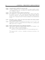
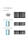
D Pin
D.1
D.2
D.3
D.4
D.5
Assignments
VGA HD-15 . . . . . . . . .
RJ 45 Connector Ethernet .
RJ 45 Connector ISDN . . .
Serial SUB-D 9 Connector 1
KVM 15 pin connector . . .
E Peppercon Warranty information
vii
.
.
.
.
.
.
.
.
.
.
.
.
.
.
.
.
.
.
.
.
.
.
.
.
.
.
.
.
.
.
.
.
.
.
.
.
.
.
.
.
.
.
.
.
.
.
.
.
.
.
.
.
.
.
.
.
.
.
.
.
.
.
.
.
.
.
.
.
.
.
.
.
.
.
.
.
.
.
.
.
.
.
.
.
.
.
.
.
.
.
.
.
.
.
.
.
.
.
.
.
.
.
.
.
.
.
.
.
.
.
.
.
.
.
.
.
.
.
.
.
.
.
.
.
.
.
.
.
.
.
.
.
.
.
.
.
.
.
.
.
.
.
.
.
.
.
.
.
.
.
71
71
71
71
72
72
73
F Specifications
75
F.1 Size and Weight . . . . . . . . . . . . . . . . . . . . . . . . . . . . . . . . . . . . . 75
F.2 Environmental . . . . . . . . . . . . . . . . . . . . . . . . . . . . . . . . . . . . . 75
G Operation advices
77
viii
Contents
List of Figures
1.1
1.2
1.3
Front Side . . . . . . . . . . . . . . . . . . . . . . . . . . . . . . . . . . . . . . . .
Rear Side . . . . . . . . . . . . . . . . . . . . . . . . . . . . . . . . . . . . . . . .
Top part of the Remote Console . . . . . . . . . . . . . . . . . . . . . . . . . . .
1
1
4
2.1
Total view . . . . . . . . . . . . . . . . . . . . . . . . . . . . . . . . . . . . . . . .
7
3.1
3.2
3.3
3.4
0801IP/1601IP usage scenario . . . . . . . .
0801IP/1601IP Front Side Connectors . . .
Rear Side Connectors . . . . . . . . . . . .
Connections of 0801IP/1601IP KVM signals
5.1
5.2
5.3
5.4
5.5
5.6
5.7
5.8
5.9
5.10
5.11
5.12
5.13
5.14
5.15
5.16
5.17
5.18
5.19
5.20
5.21
5.22
5.23
5.24
5.25
5.26
5.27
5.28
5.29
5.30
Internet Explorer showing the encryption key length
0801IP/1601IP KVM menu . . . . . . . . . . . . . .
0801IP/1601IP login screen . . . . . . . . . . . . . .
0801IP/1601IP home menu window . . . . . . . . . .
Remote Console window showing a desktop screen .
Example for the Chat window . . . . . . . . . . . . .
Video Settings in HTML frontend . . . . . . . . . .
Video Settings Panel . . . . . . . . . . . . . . . . . .
Custom Video Modes . . . . . . . . . . . . . . . . .
Example of Remote Console settings . . . . . . . . .
Telnet Console . . . . . . . . . . . . . . . . . . . . .
External Power Switch Option . . . . . . . . . . . .
Power Switch Status . . . . . . . . . . . . . . . . . .
Keyboard/Mouse settings . . . . . . . . . . . . . . .
KVM Settings . . . . . . . . . . . . . . . . . . . . . .
Assigning power ports to KVM ports . . . . . . . . .
User/Group Management . . . . . . . . . . . . . . .
User/Group Permissions panel . . . . . . . . . . . .
Port Access Permissions panel . . . . . . . . . . . . .
0801IP/1601IP network settings . . . . . . . . . . . .
Dynamic DNS Scenario . . . . . . . . . . . . . . . .
Dynamic DNS configuration panel . . . . . . . . . .
Serial Settings . . . . . . . . . . . . . . . . . . . . . .
External Power Option Settings . . . . . . . . . . . .
Authentication settings panel . . . . . . . . . . . . .
Security settings . . . . . . . . . . . . . . . . . . . .
SSL Certificate Signing Request . . . . . . . . . . . .
SSL Certificate Upload . . . . . . . . . . . . . . . . .
Maintenance . . . . . . . . . . . . . . . . . . . . . .
Panel for uploading a new firmware . . . . . . . . . .
. . . . . . . . . . . . . . . . . . . .
. . . . . . . . . . . . . . . . . . . .
. . . . . . . . . . . . . . . . . . . .
to the controlled and local systems
.
.
.
.
.
.
.
.
.
.
.
.
.
.
.
.
.
.
.
.
.
.
.
.
.
.
.
.
.
.
.
.
.
.
.
.
.
.
.
.
.
.
.
.
.
.
.
.
.
.
.
.
.
.
.
.
.
.
.
.
.
.
.
.
.
.
.
.
.
.
.
.
.
.
.
.
.
.
.
.
.
.
.
.
.
.
.
.
.
.
.
.
.
.
.
.
.
.
.
.
.
.
.
.
.
.
.
.
.
.
.
.
.
.
.
.
.
.
.
.
.
.
.
.
.
.
.
.
.
.
.
.
.
.
.
.
.
.
.
.
.
.
.
.
.
.
.
.
.
.
.
.
.
.
.
.
.
.
.
.
.
.
.
.
.
.
.
.
.
.
.
.
.
.
.
.
.
.
.
.
.
.
.
.
.
.
.
.
.
.
.
.
.
.
.
.
.
.
.
.
.
.
.
.
.
.
.
.
.
.
.
.
.
.
.
.
.
.
.
.
.
.
.
.
.
.
.
.
.
.
.
.
.
.
.
.
.
.
.
.
.
.
.
.
.
.
.
.
.
.
.
.
.
.
.
.
.
.
.
.
.
.
.
.
.
.
.
.
.
.
.
.
.
.
.
.
.
.
.
.
.
.
.
.
.
.
.
.
.
.
.
.
.
.
.
.
.
.
.
.
.
.
.
.
.
.
.
.
.
.
.
.
.
.
.
.
.
.
.
.
.
.
.
.
.
.
.
.
.
.
.
.
.
.
.
.
.
.
.
.
.
.
.
.
.
.
.
.
.
.
.
.
.
.
.
.
.
.
.
.
.
.
.
.
.
.
.
.
.
.
.
.
.
.
.
.
.
.
.
.
.
.
.
.
.
.
.
.
.
.
.
.
.
.
.
.
.
.
.
.
.
.
.
.
.
.
.
.
.
.
.
.
.
.
.
.
.
.
.
.
.
.
.
.
.
.
.
.
.
.
.
.
.
.
.
.
.
.
.
.
.
.
.
.
.
.
.
.
.
.
.
.
.
.
11
11
12
13
.
.
.
.
.
.
.
.
.
.
.
.
.
.
.
.
.
.
.
.
.
.
.
.
.
.
.
.
.
.
20
20
24
26
27
30
33
33
34
35
37
38
39
40
41
42
43
44
46
47
48
48
50
50
51
53
57
58
58
59
x
List of Figures
5.31 Panel to update a new firmware that was previously uploaded . . . . . . . . . . . 60
C.1 English (US) Keyboard Layout, used for key codes . . . . . . . . . . . . . . . . . 69
List of Tables
1.1
1.2
Initial configuration . . . . . . . . . . . . . . . . . . . . . . . . . . . . . . . . . .
Serial parameters . . . . . . . . . . . . . . . . . . . . . . . . . . . . . . . . . . . .
3
3
2.1
Host system failures and how they are detected . . . . . . . . . . . . . . . . . . .
9
4.1
4.2
Initial IP configuration . . . . . . . . . . . . . . . . . . . . . . . . . . . . . . . . . 15
Serial line parameters . . . . . . . . . . . . . . . . . . . . . . . . . . . . . . . . . 16
5.1
5.2
Meaning of the main menu 0801IP/1601IP features . . . . . . . . . . . . . . . . . 25
0801IP/1601IP user and group permissions . . . . . . . . . . . . . . . . . . . . . 45
B.1 0801IP/1601IP Video Modes . . . . . . . . . . . . . . . . . . . . . . . . . . . . . 67
C.1 Key Names . . . . . . . . . . . . . . . . . . . . . . . . . . . . . . . . . . . . . . . 69
xii
List of Tables
1 The Quick Installation Guide
Installation
The 0801IP/1601IP redirects local keyboard, mouse and video data to a remote administration
console. All data is transmitted via IP. The 0801IP/1601IP can be used in a multi administrator
and multi server environment as well. Besides this, the 0801IP/1601IP is a KVM switch which
can also be used with a local console.
This manual applies to both 0801IP and 1601IP devices unless otherwise noted.
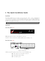
Connectors
Front Side (Figure 1.1)
Figure 1.1: Front Side
ETH ACT Indicates activity on the Ethernet connection
SYS OK
Indicates whether the 0801IP/1601IP system is running or not
Rear Side (Figure 1.2)
Figure 1.2: Rear Side
SUB-D 9 Serial The standard serial connector is used in multiple ways:
Serial output for modem dial in connection
Serial pass-through via Telnet
Power switch option
2
CHAPTER 1. THE QUICK INSTALLATION GUIDE
Initial configuration
SUB-D KVM
16 KVM connectors for keyboard, video, mouse signals
Power supply
A power supply with the following parameters must be attached:
Voltage: 12 V
Current: >= 2 A
RJ 45 Ethernet UTP3/5 cables may be used to connect the 0801IP/1601IP to an Ethernet
LAN
Reset Button
Use a ballpoint pen or a similar sharp device to reset the 0801IP/1601IP
ETH ACT
Indicates activity on the Ethernet connection
SYS OK
Indicates whether the 0801IP/1601IP system is running or not
In case you want to connect a local console to the host system besides the 0801IP/1601IP or
when using 0801IP/1601IP as a KVM switch, you can attach monitor, keyboard and mouse to
the according connectors on its rear.
Connecting the 0801IP/1601IP to the host system
In order to connect the KVM signals of the host systems to the 0801IP/1601IP perform the
following steps:
1. Connect the power supply on 0801IP/1601IP
2. Connect the 1-to-3 KVM cable to PS2/PS2/Video cable to one of the KVM connectors
on 0801IP/1601IP
3. Connect the (purple) PS/2 Keyboard jack to the keyboard connector of the host system
4. Connect the (green) PS/2 mouse plug to the mouse connector of the host system
5. Connect the VGA HD-15 connector to the VGA monitor output of the host system
6. Connect Ethernet and/or modem, depending how you want to access 0801IP/1601IP
In case you want to connect a local console to the host system besides 0801IP/1601IP or you
want to use 0801IP/1601IP as a KVM switch, you may attach monitor, keyboard and mouse
to the connectors on the rear side.
ATTENTION! Do not plug a KVM cable into the local monitor port of 0801IP/1601IP.
Doing so may damage the system.
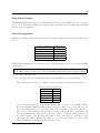
Video modes
The 0801IP/1601IP recognizes a limited number of common video modes. When running X11
on the host system, please don’t use any custom modelines with special video modes. If done so,
the 0801IP/1601IP may not be able to detect these. You are on the safe side with all standard
VESA video modes. Please refer to Appendix B on page 67 for a list of all known modes.
3
KVM Switch Function
The 0801IP/1601IP may be used as a KVM switch. Press the left <CTRL> key twice followed
by (’1’∼’8’1 ). If the left <CTRL> key is pressed three times an On-Screen Display (OSD) with
various options is displayed.
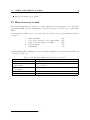
Initial IP configuration
Initially the 0801IP/1601IP network interface is configured with the parameters shown in Table 1.1.
Table 1.1: Initial configuration
parameter
value
IP auto configuration DHCP
IP address
Netmask
255.255.255.0
Gateway
none
IP access control
disabled
If this initial configuration does not meet your local requirements, you need to do the initial IP
configuration.
Note:
If the DHCP connection fails on boot up, the 0801IP/1601IP will not have an IPv4 address.
Use one of the following ways:
1. Connect the enclosed Null Modem Cable to the serial interface on the rear side.
The serial interface needs to be adjusted with the parameters shown in table Table 1.2:
Table 1.2: Serial
parameter
Bits/second
Data bits
Parity
Stop bits
Flow Control
parameters
value
115200
8
No
1
None
Use a terminal software (e.g. hyperterm or minicom) to connect to the 0801IP/1601IP.
Reset the 0801IP/1601IP and immediately press the < ESC > key. You will see some
device information and a ’=>’ prompt. Enter the command ’config’ and press the <
Enter > key. After waiting a few moments you may configure IP auto configuration, IP
address, net mask and default gateway. Pressing < Enter > without entering values does
not change settings. The gateway value must be set to 0.0.0.0 (for no gateway) or any
other value. You will be asked if the values are correct and get a chance to correct them.
After confirming, the 0801IP/1601IP performs a reset.
1
for 1601IP also ’A’∼’H’
4
CHAPTER 1. THE QUICK INSTALLATION GUIDE
2. Use an Ethernet cable to connect the 0801IP/1601IP to a subnet where a DHCP server is
available. After the DHCP server has assigned an IP address to the 0801IP/1601IP you
can use the web interface to configure the device (see Section 4.1.1 on page 15 for details).
Web interface
The 0801IP/1601IP may be accessed using a standard web browser. You may use the HTTP
protocol or a secure encrypted connection via HTTPS. Just enter the configured IP address of
the 0801IP/1601IP into your web browser. Initially there is only one user configured who has
unrestricted access to all the 0801IP/1601IP features:
Login name
Password
super
0801ip/1601ip (depending on the actual device)
Please login and change the password immediately according to your own policies.
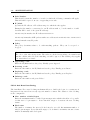
The Remote Console
The Remote Console is the redirected screen, keyboard and mouse of the remote host system to which 0801IP/1601IP is attached. The web browser which is used for accessing the
0801IP/1601IP has to supply a Java Runtime Environment version 1.1 or higher. The Remote
Console will behave exactly the same way as if you were sitting directly in front of the screen
of your remote system. That means keyboard and mouse can be used in the usual way. Open
the console by choosing the appropriate link in the navigation frame of the HTML frontend.
Figure 1.3 shows the top of the Remote Console.
Figure 1.3: Top part of the Remote Console
There are some options to choose from, the important ones are the following:
Auto Adjust button
If the video displayed is of bad quality or distorted in some way, press this button and
wait a few seconds while the 0801IP/1601IP tries to adjust itself for the best possible
video quality.
Sync Mouse
Choose this option in order to synchronize the local with the remote mouse cursor. This is
especially necessary when using accelerated mouse settings on the host system. In general
there is no need to change mouse settings on the host.
Video Settings in Options Menu
5
This opens a new window with elements to control the the 0801IP/1601IP Video Settings.
You can change some values, for instance related to brightness and contrast of the picture
displayed, which may improve the video quality. It is also possible to revert to the default
settings for all video modes or only the current one.
6
CHAPTER 1. THE QUICK INSTALLATION GUIDE
2 Introduction
Features
The 0801IP/1601IP defines a new class of remote KVM access devices (see Figure 2.1). 0801IP/1601IP 1
combines a 8/16-port KVM switch with digital remote KVM access via IP networks and comprehensive system management.
The 0801IP/1601IP offers convenient, remote KVM access and control via LAN or Internet. It
captures, digitizes, and compresses video and transmits it with keyboard and mouse signals to
and from a remote computer. The 0801IP/1601IP provides a non-intrusive solution for remote
access and control. Remote access and control software runs on its embedded processors only
but not on mission-critical servers, so that there is no interference with server operation or
impact on network performance.
Figure 2.1: Total view
Furthermore, the 0801IP/1601IP is complete KVM switch and offers additional remote power
management with the help of optional available devices.
Features of the 0801IP/1601IP are:
KVM (keyboard, video, mouse) access over IP or analogous telephone line.
No impact on server or network performance
Automatically senses video resolution for best possible screen capture
High-performance mouse tracking and synchronization
Port to connect a user console for direct analogous access to KVM switch
1
0801IP/1601IP— 8/16-port KVM and KVMIP
8
CHAPTER 2. INTRODUCTION
Local Mouse suppression (only when using SUN’s Java Virtual Machine)
0801IP/1601IP supports consoles consisting of PS/2 style keyboards, PS/2 style mouse and HD
15 video output. Please refer to Appendix D.1 on page 71 for more details. 0801IP/1601IP
will automatically detect the current video mode of the console, however manual fine tuning is
recommended to receive the best video quality. 0801IP/1601IP will accept video streams up to
110 MHz dot clock. This results in a screen resolution of 1280x1024 dots with a frame rate of
60 Hz.
Additionally supported is the use of an external ePowerSwitch to switch power of the connected
hosts.
0801IP/1601IP System Components
0801IP/1601IP is a fully configured stand-alone product consuming a 1U 19” rack mount chassis
space.
Each 0801IP/1601IP (8420051/8420064) is shipped with:
1. Base unit
2. External power supply
3. Power cord
4. Rack mount kit incl. screws
5. Installation and User Manual on CD-ROM
6. Quick installation guide
7. NULL modem cable
Each 1601IP (Item No: 8420061) package contains additionally:
1. 4 CPU cables 3m
2. 12 CPU cables 1.8m
Each 0801IP (Item No: 8420063) package contains additionally:
1. 8 CPU cables 1.8m
2.1 When the server is up and running
0801IP/1601IP gives you full control over the remote server. The Management Console allows
you to access the remote server’s graphics, keyboard and mouse and to send special commands
to the server.
You can also perform periodic maintenance of the server. Using the Console Redirection Service,
you are able to do the following:
Reboot the system (a graceful shutdown).
Watch the boot process.
Boot the system from a separate partition to load the diagnostic environment.
2.2. WHEN THE SERVER IS DEAD
9
Run special diagnostic programs.
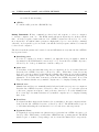
2.2 When the server is dead
Obviously, fixing hardware defects is not possible using a remote management device. Nevertheless 0801IP/1601IP gives the administrator valuable information about the type of a hardware
failure.
Serious hardware failures can be categorized into five different categories with different chances
to happen 2 :
1.
2.
3.
4.
5.
Hard disk failure
Power cable detached, power supply failure
CPU, Controller, main board failure
CPU fan failure
RAM failure
50%
28%
10%
8%
4%
Using 0801IP/1601IP, administrators can determine which kind of serious hardware failure has
occurred (see Table 2.1).
Table 2.1: Host
Type of failure
Hard disk failure
Power cable detached, power
supply failure
CPU, Controller,
main
board failure
CPU fan failure
RAM failure
2
system failures and how they are detected
Detected by
Console screen, CMOS set-up information
Server remains in power off state after power on command
has been given.
Power supply is on, but there is no video output.
By server specific management software
Boot-Sequence on boot console
According to a survey made by the Intel Corp.
10
CHAPTER 2. INTRODUCTION
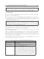
3 Installation
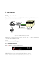
3.1 Operation Overview
Figure 3.1 shows the connections of 0801IP/1601IP to its host, to peripheral devices, to the
power source and to the local area network.
Figure 3.1: 0801IP/1601IP usage scenario
0801IP/1601IP redirects local keyboard, mouse, and video data to a remote administration
console. All data is transmitted via IP.
3.2 Connectors and Jumpers
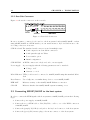
3.2.1 Front Side Connectors
Figure 3.2 shows the connectors on the front side.
Figure 3.2: 0801IP/1601IP Front Side Connectors
ETH ACT Indicates activity on the 0801IP/1601IP Ethernet connection
SYS OK
Indicates whether the 0801IP/1601IP system is running or not
12
CHAPTER 3. INSTALLATION
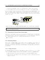
3.2.2 Rear Side Connectors
Figure 3.3 shows the connectors on the rear side.
Figure 3.3: Rear Side Connectors
In case you want to connect a local console to the host system besides 0801IP/1601IP or when
using 0801IP/1601IP as a KVM switch, you can attach monitor, keyboard and mouse to the
according connectors on its rear.
SUB-D 9 Serial The standard serial connector is used in multiple ways:
Serial output for modem dial in connection
Serial pass-through via Telnet
Power switch option
Initial configuration
SUB-D KVM
16 KVM connectors for keyboard, video, mouse signals
Power supply
A power supply with the following parameters can be attached:
Voltage: 12 V
Current: >= 2 A
RJ 45 Ethernet UTP3/5 cables can be connected to 0801IP/1601IP using this standard RJ 45
Jack
Reset Button
Use a ballpoint or a similar sharp device to reset 0801IP/1601IP
ETH ACT
Indicates activity on the 0801IP/1601IP Ethernet connection
SYS OK
Indicates whether the 0801IP/1601IP system is running or not
3.3 Connecting 0801IP/1601IP to the host system
In order to connect the KVM signals of the host systems to 0801IP/1601IP perform the following
steps:
1. Connect the power supply on 0801IP/1601IP
2. Connect the 1-to-3 KVM cable to PS2/PS2/Video cable to one of the KVM connectors
on 0801IP/1601IP
3. Connect the (purple) PS/2 Keyboard jack to the keyboard connector of the host system
4. Connect the (green) PS/2 mouse plug to the mouse connector of the host system
3.3. CONNECTING 0801IP/1601IP TO THE HOST SYSTEM
13
5. Connect the VGA HD-15 connector to the VGA monitor output of the host system
6. Connect Ethernet and/or modem, depending how you want to access 0801IP/1601IP
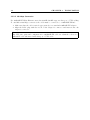
In case you want to connect a local console to the host system besides 0801IP/1601IP or you
want to use 0801IP/1601IP as a KVM switch, you may attach monitor, keyboard and mouse to
the connectors on the rear side. Figure 3.4 shows the resulting connections to the host systems
and the local console.
Figure 3.4: Connections of 0801IP/1601IP KVM signals to the controlled and local systems
ATTENTION! Don’t plug a KVM cable into the local monitor port of 0801IP/1601IP.
Doing so may damage the system.
3.3.1 Connecting the External Power Switch Option
Please refer to the manual of the Peppercon external power switch option or a third party
external power option to connect those external devices to one of the serial interface on the rear
side of 0801IP/1601IP. By the date of printing this manual supported options are:
ePowerSwitch
3.3.2 Connecting Ethernet
The rear side of 0801IP/1601IP provides a RJ45 connector for Ethernet. The connector is
used either for a 100 Mbps 100BASE-TX connection or for a 10 Mbps 10BASE-T connection.
The adapter can sense the connection speed and will adjust to the appropriate operation mode
automatically.
3.3.2.1 10 Mbps Connection
For 10BASE-T Ethernet networks, the Fast Ethernet adapter uses Category 3, 4, or 5 UTP
cable. To establish a 10 Mbps connection, the cable must be connected to a 10BASE-T hub.
1. Make sure that the cable is wired appropriately for a standard 10BASE-T adapter.
2. Align the RJ45 plug with the notch on the adapter’s connector and insert it into the
adapter’s connector.
14
CHAPTER 3. INSTALLATION
3.3.2.2 100 Mbps Connection
For 100BASE-TX Fast Ethernet networks, 0801IP/1601IP supports Category 5 UTP cabling.
To establish a 100 Mbps connection, the cable must be connected to a 100BASE-TX hub.
1. Make sure that the cable is wired appropriately for a standard 100BASE-TX adapter.
2. Align the RJ45 plug with the notch on the adapter’s connector and insert it into the
adapter’s connector.
Note:
The UTP wire pairs and configuration for 100BASE-TX cable are identical to those for
10BASE-T cable when used with Category 5 UTP cable.
4 Configuration
4.1 Initial Configuration
0801IP/1601IP’s communication interfaces are all based on TCP/IP. It comes pre-configured
with the IP configuration listed in Table 4.1.
Table 4.1: Initial IP configuration
Parameter
Value
IP auto configuration
DHCP
IP-Address
Net-mask
Default-Gateway
none
IP access control
disabled
LAN interface speed
auto
LAN interface duplex mode auto
In case this initial configuration doesn’t meet your requirements there is an initial IP configuration necessary in order to access 0801IP/1601IP for the first time. This chapter describes
different possibilities to accomplish that.
4.1.1 Initial configuration via DHCP server
By default, 0801IP/1601IP will try to contact a DHCP server in the subnet to which it is
physically connected. If a DHCP server is found it may provide a valid IP address, gateway
address and net mask. Before you connect the device to your local subnet be sure to complete
the corresponding configuration of your DHCP server. It is recommended to configure a fixed
IP assignment to the MAC address of 0801IP/1601IP. You can find the MAC address on the
outside of the shipping box and labelled on the bottom side. If the DHCP connection fails on
boot up, 0801IP/1601IP will not have an IPv4 address.
4.1.2 Initial configuration via serial interface
0801IP/1601IP has a serial line interface at its rear side (refer to Section 3.2 on page 11). The
connector is compliant to RS 232 serial line standard. The serial interface has to be configured
with the parameters given in Table 4.2 on the following page.
To actually configure 0801IP/1601IP via the serial interface, reset 0801IP/1601IP and immediately press ESC. You will see some device information and a ’=>’ prompt. Enter ’config’, press
Enter and wait a few seconds for the configuration questions to appear.
As you go along you will see the following lines, which you have to answer or to which you may
provide the default value by pressing Enter.
16
CHAPTER 4. CONFIGURATION
Table 4.2: Serial line parameters
Parameter
Value
Bits/second
115200
Data bits
8
Parity
No
Stop bits
1
Flow Control None
IP auto configuration (none/dhcp/bootp) [none]:
IP [192.168.1.22]:
NetMask [255.255.255.0]:
Gateway (0.0.0.0 for none) [0.0.0.0]:
Enable IP Access Control (yes/no) [no]:
LAN interface speed (auto/10/100) [auto]:
LAN interface duplex mode (auto/half/full) [auto]:
IP auto-configuration
With this option you can specify whether 0801IP/1601IP should fetch it’s network settings
from a DHCP or BOOTP server. For DHCP you have to enter dhcp and for BOOTP
supply bootp accordingly. If you specify none then IP auto-configuration is disabled and
you will subsequently be asked for the following network settings.
IP address
The IP address the 0801IP/1601IP should use. This option is only available if IP autoconfiguration is disabled.
Subnet mask
The mask of the connected IP subnet. This option is only available if IP auto-configuration
is disabled.
Gateway address
The IP address of the default router of the connected IP subnet. If you have no default
router, you may enter 0.0.0.0. This option is only available if IP auto-configuration is
disabled.
Enable IP Access Control
‘Enable IP Access Control’ allows you to switch IP packet filtering on or off. It is mainly
intended to re-enable access to 0801IP/1601IP after a faulty IP access control configuration
has been activated. Refer to Section 5.6.9.3 on page 54 for more information about IP
access control.
LAN interface speed
‘LAN interface speed’ allows you to switch the LAN Ethernet interface speed to autosensing/autonegotiation (auto), 10Mbps (10) or 100Mbps (100).
LAN interface duplex mode
The last question ‘LAN interface duplex mode’ allows you to switch LAN interface mode
to autosensing/autonegotiation (auto), half duplex (half) or full duplex (full).
There may be default values which are enclosed in brackets. If you want to use the default value
of an option then you just need to press the Enter key.
You will be asked if the values are correct and get a chance to correct them. After confirming,
4.1. INITIAL CONFIGURATION
17
0801IP/1601IP performs a reset.
4.1.3 Mouse, Keyboard and Video configuration
There are two interfaces between 0801IP/1601IP and the host for transmitting keyboard and
mouse data: USB and PS/2. The correct operation of the remote mouse depends on several
settings which will be discussed in the following:
4.1.3.1 0801IP/1601IP mouse settings
The 0801IP/1601IP settings for the host’s keyboard type must be correct in order to make
remote keyboard work properly. Check the settings in the 0801IP/1601IP front-end. See Section 5.5.2 on page 38 for details.
4.1.3.2 Host system mouse settings
Note:
The following limitations do not apply in case of USB and Mouse Type MS Windows 2000
and newer.
While 0801IP/1601IP works with accelerated mice and is able to synchronize the local with the
remote mouse pointer (see Section 5.4.3 on page 31), there are the following limitations which
may prevent this synchronization from working properly:
Special Mouse Driver
There are mouse drivers, which influence the synchronization process leading to desynchronized mouse pointers. If this happens, make sure you don’t use a special vendor-specific
mouse driver on your host system.
Windows XP Mouse Settings
Windows XP knows a setting to improve mouse acceleration, which has to be deactivated.
4.1.3.3 0801IP/1601IP Video Modes
0801IP/1601IP recognizes a limited number of common video modes. When running X11 on
the host system, please don’t use any custom modelines with special video modes. If done so,
0801IP/1601IP may not be able to detect these. You are on the safe side with all standard
VESA video modes. Please refer to Appendix B on page 67 for a list of all known modes.
18
CHAPTER 4. CONFIGURATION
5 Usage
5.1 Prerequisites
The 0801IP/1601IP features an embedded operating system and the according applications
offering a variety of standardized interfaces. The functionality is exposed to the user via these
interfaces. This chapter will describe all of these interfaces and how to use them in detail. All
the interfaces are accessed using the TCP/IP protocol family, thus they can be used equally over
the built-in Ethernet adapter or over modem.Additionally it is possible to use 0801IP/1601IP
as a normal 8/16-port KVM switch, explained in section 5.2 on the next page. The following
interfaces are supported:
1. HTTP/HTTPS
The most complete access is provided by an embedded web server. Thus the 0801IP/1601IP
environment can be entirely controlled by a standard web browser. Depending on the web
browser you can access the 0801IP/1601IP using the unsecured HTTP protocol or, in
case the browser supports it, the encrypted HTTPS protocol. It is recommended to use
HTTPS whenever possible.
2. Telnet
A standard Telnet client can be used to access an arbitrary device connected to 0801IP/1601IP’s
serial port via a terminal mode.
Since the primary interface of 0801IP/1601IP is the HTTP interface this chapter is mainly
concerning this topic. Other interfaces are explained in their according subtopics.
In order to use the Remote Console window of your managed host system the browser has to
come with a Java Runtime Environment version 1.1 or higher. But even if the used browser
has no Java support, for instance on small handheld devices, you are still able to maintain your
remote host system using the administration forms displayed by the browser itself.
We recommend the following browsers for an unsecured connection to 0801IP/1601IP.
Microsoft Internet Explorer version 5.0 or higher on Windows 98, Windows ME and
Windows 2000, Windows XP
Netscape Navigator 7.0 or Mozilla 1.0 on Windows 98, Windows ME, Windows 2000,
Windows XP, Linux and other UNIX like Operating Systems
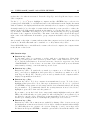
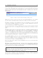
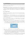
In order to access the remote host system using a securely encrypted connection you need a
browser that supports the HTTPS protocol. Strong security is only assured by using key length
of at least 128 Bit. Many old browsers don’t have a strong 128 Bit encryption algorithm due
to former export regulations of US authorities. For instance Internet Explorer 5.0, that comes
as part of Windows ME and Windows 2000 supports a key length of 56 Bit only. You can read
about the key length of your Internet Explorer under the menu points ? and Info. The dialog
box shows also a hyperlink that leads you to information on how to upgrade your browser to a
state of the art encryption scheme. Figure 5.1 on the following page shows the dialog presented
by Internet Explorer 6.0.
20
CHAPTER 5. USAGE
However the US export regulations have been declared obsolete recently. Therefore, new browser
versions do support strong encryption.
We recommend the following browser for a secured connection to 0801IP/1601IP.
Microsoft Internet Explorer version 5.5 or higher on Windows 98, Windows ME and
Windows 2000 and Windows XP
Netscape Navigator 7.0 or Mozilla 1.0 on Windows 98, Windows ME, Windows 2000,
Windows XP, Linux and other UNIX like Operating Systems
Figure 5.1: Internet Explorer showing the encryption key length
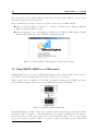
5.2 Using 0801IP/1601IP as a KVM switch
0801IP/1601IP may be used as a KVM switch without remote functionality. Just connect a
local monitor, keyboard and mouse as described in Section 3.3 on page 12.
This operation mode is available via an OSD1 , accessible by hitting the <CTRL> key twice
(for the Hotkey menu) or three times (for the KVM menu as shown in Figure 5.2.
Figure 5.2: 0801IP/1601IP KVM menu
In the KVM menu you will see a list of the computers with corresponding port numbers, names
and status. The port number of the currently selected computer is displayed in red, same as
the front indicator, at the upper-right corner of the OSD menu. The color of a device name
is green if it has power and is ready for operation, or white as it has no power. OSD menu
1
OSD – On-Screen-Display
5.2. USING 0801IP/1601IP AS A KVM SWITCH
21
updates the color when it is activated. Press the <PageUp> and <PageDown> keys to view 8
other computers.
Use the ’↑’, ’↓’, ’1’∼’8’2 keys to highlight a computer and the <ENTER> key to select it. Or,
you may press <ESCAPE> to exit OSD and remove the OSD menu from the display; the status
window returns to the display and indicates the currently selected computer or operating status.
A triangle mark (’B’) to the right of a name indicates that the port is cascaded to a Slave; the
number at the left of the triangle mark shows the number of ports the Slave has, i.e. 8B for an
8-port Switch. <ENTER> key brings you one level down and another screen pops up listing
the names of the computers on that Slave. The name of the Slave will be shown at the upper
right corner of the OSD menu. It is useful to group computers and still be able to see the group
name.
An eye mark on the right of a name indicates that this computer is selected and monitored in
Scan mode. In OSD, this mark can be switched on or off by function key <F2>.
Press <ESCAPE> key to exit OSD and to return to the selected computer; the computer name
is also shown on the screen.
OSD Function Keys
Function key <F1>
To edit name entry of a computer or a slave with up to 14 characters. First, highlight a port then press <F1> followed by name entry. Valid characters are ’A’∼’Z’,
’0’∼’9’ and the dash character. Lowercase letters are converted to uppercase ones. Press
<BACKSPACE> to delete a letter one at a time. Non-volatile memory stores all name
entries until you change, even if the unit is powered down.
Function key <F2>
Function key <F2>: To switch the eye mark of a computer on or off. First, use the ’↑’
and ’↓’ arrow keys to highlight it, then press <F2> to switch its eye mark on or off. If
Scan Type is ’Ready PC’, only the power-on and eye mark selected computers will be
displayed sequentially in Scan mode.
Function key <F3>
Function key <F3>: To lock a computer from unauthorized access. To lock a device,
highlight it then press <F3>. Now, enter up to 4 characters (’A’∼’Z’, ’0’∼’9, ’-’) followed
by <ENTER> as new password. A Security-enabled device is marked with a lock following
its port number. To permanently disable the security function from a locked device,
highlight it, press <F3> then enter the password.
If you want to access the locked device temporarily, simply highlight it and press <ENTER>, the OSD will ask you for the password. After entering the correct password, you
are allowed to use the device. This device is automatically re-locked once you switch to
another port. During Scan mode, OSD skips the password-protected devices.
Function key <F4>
Function key <F4>: More functions are available by hitting <F4>. A new screen pops
up displaying more functions as described below. Most of them are marked with a triangle
(’B’) indicating there are options to choose from. Using the ’↑’ and ’↓’ arrow keys, select
the functions and press <ENTER>. Available options will be shown in the middle of the
2
also ’A’∼’H’ for 1601IP
22
CHAPTER 5. USAGE
screen. Again, use the ’↑’ and ’↓’ arrow keys to view options then press <ENTER> to
select it. You can press <ESCAPE> to exit at any time.
– Auto scan
In this mode, the KVM switch automatically switches from one power-on computer
to the next sequentially in a fixed interval. During Auto Scan mode, the OSD displays
the name of the selected computer. When Auto Scan detects any keyboard or mouse
activity, it suspends the scanning till activity stops; it then resumes with the next
computer in sequence. To abort the Auto Scan mode, press the left <CTRL> twice,
or, press any front button. Scan Type and Scan Rate set the scan pattern. Scan
Type (<F4>, More, Scan Type) determines if scanned computers must also be eye
mark selected. Scan Rate (<F4>, More, Scan Rate) sets the display interval when
a computer is selected before selecting the next one.
– Manual scan
Scan through power-on computers one by one by keyboard control. You can type
(<F4>, More, Scan Type) to determine if scanned computers must also be eye mark
selected. Press the up arrow key ’↑’ to select the previous computer and the down
arrow key ’↓’ to select the next computer. Press any other key to abort the Manual
Scan mode.
– Scan Type
Ready PC +Eye symbol: In Scan mode, scan through power-on and eye mark selected
computers. Ready PC: In Scan mode, scan through power-on computers. Eye symbol
only: In Scan mode, scan through any selected computer regardless of computer
power status. The non-volatile memory stores the Scan Type setting.
– Scan Rate
Sets the duration of a computer displayed in Auto Scan mode. The options are 3
seconds, 8 seconds, 15 seconds and 30 seconds. The non-volatile memory stores the
Scan Rate setting.
– Keyboard Speed
It is possible to override the typematic settings in BIOS and in the operating system
on the connected hosts. Available speed options are Low, Middle, Fast and Faster
as 10, 15, 20 and 30 characters/sec respectively. The non-volatile memory stores the
Keyboard Speed setting.
– Hotkey Menu
When you hit the left <CTRL> key twice within two seconds, the ”Hotkey Menu”
appears displaying a list of hotkey commands if the option is On. The ’Hotkey Menu’
can be turned Off if you prefer not to see it when the left <CTRL> key is hit twice.
The non-volatile memory stores the Hotkey Menu setting.
– CH Display
Auto Off: After you select a computer, the port number and name of the computer
will appear on the screen for 3 seconds then disappear automatically. Always On:
The port number and name of a selected computer and/or OSD status displayed on
the screen all the time. The non-volatile memory stores the CH Display setting.
– Position
The position of the selected computer and/or OSD status displays on screen during
operation. The actual display position shifts due to different VGA resolution, the
higher the resolution the higher the displayed position. The non-volatile memory
5.2. USING 0801IP/1601IP AS A KVM SWITCH
23
stores the Position setting.
<ESC>
To exit the OSD, press the <ESCAPE> key.
Hotkey Commands Hotkey command is a short keyboard sequence to select a computer,
to activate computer scan, etc. The KVM switch interprets keystrokes for hotkeys all the
time. A hotkey sequence starts with two left <CTRL> keystrokes followed by one or two
more keystrokes. A built-in buzzer generates a high-pitch beep for correct hotkey command;
otherwise, one low-pitch beep for error will occur and the bad key sequence will not be forwarded
to the selected computer.
The short form hotkey menu can be turned on as an OSD function every time the left <CTRL>
key is pressed twice.
Switching ports
To select a computer by hotkey command, you must know its port number, which is
determined by the KVM Switch connection (’1’∼’8’3 ). Press the left <CTRL> key twice,
followed by one of the port numbers to switch to this port.
Auto scan
To start Auto Scan, automatically scan power-on computers one by one at a fixed interval.
Press the left <CTRL> key twice, followed by <F1>. When Auto Scan detects any
keyboard or mouse activity, it suspends the scanning till activity stops; it then resumes
with the next computer in sequence. The length of the Auto Scan interval (Scan Rate) is
adjustable. To abort the Auto Scan mode, press the left <CTRL> key twice. Note: Scan
Type determines whether an eye-marked computer is to be displayed during Auto Scan.
Manual scan
Manual Scan enables you to manually switch back and forth between power-on computers.
Press the left <CTRL> key twice, followed by <F2>. Press ’↑’, ’↓’ to select the previous
or the next computer in sequence. And, press any other key to abort the Manual Scan.
Note: Scan Type determines whether an eye-marked computer is to be displayed during
Auto Scan.
Scan Rate
To adjust Scan Rate that sets the duration before switching to the next computer in Auto
Scan press the left <CTRL> key twice, followed by <F3>. The KVM switch beeps one
to four times indicating the scan interval of 3, 8, 15 and 30 seconds respectively.
Typematic Rate
To adjust keyboard typematic rate (characters/sec) press the left <CTRL> key twice, followed by <F4>. This setting overrides that of BIOS and any operating system. The KVM
switch beeps 1 to 4 times corresponding to 10, 15, 20 and 30 characters/sec respectively.
3
also ’A’∼’H’ for 1601IP
24
CHAPTER 5. USAGE
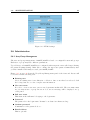
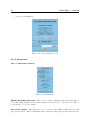
5.3 Login into 0801IP/1601IP and logout
5.3.1 Login into 0801IP/1601IP
Start your web browser and direct it to the address of your 0801IP/1601IP that has been
configured during installation. The address used might be a plain IP address or a host and
domain name, in case you have given your 0801IP/1601IP a symbolic name in the DNS.
For instance, you have to type the following into the address line of your browser for establishing
an unsecured connection:
http://<IP address of 0801IP/1601IP >/
or in case you like to use a secure connection:
https://<IP address of 0801IP/1601IP >/
This leads you to the 0801IP/1601IP login page as shown in Figure 5.3.
Figure 5.3: 0801IP/1601IP login screen
The 0801IP/1601IP has a built-in super user that has all permissions to administrate your
0801IP/1601IP:
Login name
Password
super
0801ip/1601ip (depending on the actual device)
Attention:
Please make sure to change the super user password immediately after you have installed
and firstly accessed your 0801IP/1601IP. Not changing the super user password is a severe
security risk and might result in unauthorized access to 0801IP/1601IP and the host system
with all possible consequences!
5.3. LOGIN INTO 0801IP/1601IP AND LOGOUT
25
Hints:
The browser must be configured to accept cookies, otherwise login is not possible. The
user super can not be used to login via the serial interface of 0801IP/1601IP.
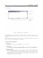
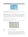
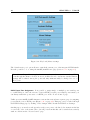
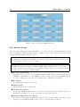
5.3.2 Main Screen
After a successful login, 0801IP/1601IP will present its main screen consisting of three frames
(see Figure 5.4 on the following page)
The upper left frame contains a home link that brings you instantly back to the home page
after you stepped down to one of the administration menu points. The logout link logs you
out of 0801IP/1601IP. That means the current session will be terminated and you have to type
username and password again to login.
Note:
The 0801IP/1601IP will log you out automatically after there is no administration activity
for half an hour. In this case each click on one of the links will lead you to the login screen
where you have to provide the login information again.
The lower left frame of the 0801IP/1601IP main window, called the menu frame, contains the
main menu that leads you to the pages for various administration tasks. The functions of the
menu frame will be described in detail during the following sections.
The different function pages selected by one of the menu links will be presented in the big right
frame, called the function frame.
On the top of the function frame you will notice a select box with port numbers and a switch
button in a schematic picture of 0801IP/1601IP. Choose one of the ports and press switch to
change the currently selected KVM port. The user logged in is only allowed to switch to ports
displayed with a green text. Ports shown in red are not accessible for the user. Have a look at
5.6.3 for details on port access permissions.
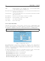
Initially the function frame contains a short summary of your 0801IP/1601IP. Table 5.1 gives
you a description of the meaning of each point.
Table 5.1: Meaning of the main menu 0801IP/1601IP features
Feature
Description
Server Power Status
Shows whether the host system is switched on or off
Firmware Version
Version number of the firmware installed on your
0801IP/1601IP
Device Management
Shows, if 0801IP/1601IP is entirely self-managed or if its
connected to a management device.
Users
Shows all currently logged in users with their identity and
the IP address from where they are logged in (note: in
case a user connected his web browser over a proxy server
the IP address field will show the IP address of the proxy
server and not that of the user machine itself). RC means
that the user has opened the Remote Console. Exclusive
is a sign that the Remote Console is opened in exclusive
mode. Idle is the time since last access during the current
session.
26
CHAPTER 5. USAGE
Figure 5.4: 0801IP/1601IP home menu window
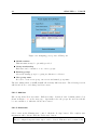
5.3.3 Logout from 0801IP/1601IP
This link logs out the current user and presents a new login screen. Please note that an automatic
logout will be performed in case there is no activity for half an hour.
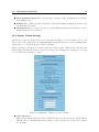
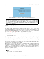
5.4 Remote Console
5.4.1 Show Remote Console
The Remote Console is the redirected screen, keyboard and mouse of the remote host system
0801IP/1601IP controls.
Starting the Remote Console causes an additional window popping up that contains a copy of
the screen of your host system (see Figure 5.5 on the facing page). The Remote Console will
behave exactly in the same way as if you were sitting directly in front of the screen of your
5.4. REMOTE CONSOLE
27
remote system. That means keyboard and mouse can be used in the usual way. However,
be aware of the fact that the remote system will react to keyboard and mouse actions with a
slight delay. The delay depends on the bandwidth of the line over which you are connected to
0801IP/1601IP.
Figure 5.5: Remote Console window showing a desktop screen
With respect to the keyboard, the very exact remote representation might lead to some confusion
as your local keyboard changes its keyboard layout according to the remote host system.
For instance, special keys on the German keyboard won’t work anymore as expected but will
result in their US English counterpart if you are using a German administration system but
your host system uses a US English keyboard layout.
You can circumvent such problems by adjusting the keyboard of your remote system to the same
mapping as your local one or by using the Soft-Keyboard that is part of the Remote Console
applet.
The Remote Console window is a Java Applet that tries to establish its own TCP connection
to 0801IP/1601IP. The protocol that is run over this connection is not HTTP or HTTPS but
a protocol called RFB (Remote Frame Buffer Protocol). Currently RFB tries to establish a
connection to port number 443. Your local network environment must allow this connection to
be made, i.e. your firewall and, in case you have a private internal network, your NAT (Network
Address Translation) settings must be configured accordingly.
In case 0801IP/1601IP is connected to your local network environment and your connection to
the Internet is available using a proxy server only without NAT being configured, the Remote
Console is very unlikely to be able to establish the according connection. This is because today’s
web proxies are not capable of relaying the RFB protocol.
In case of problems, please consult your network administrator in order to provide an appropriate
network environment.
The Remote Console window always tries to show the remote screen with its optimal size.
That means it will adapt its size to the size of the remote screen initially and after the screen
resolution of the remote screen has been changed. However, you can always resize the Remote
Console window in your local window system as usual.
Hint:
In difference to the remote host system, the Remote Console window on your local window
system is just one window among others. In order to make keyboard and mouse work, your
Remote Console window must have the local input focus.
The upper part of the Remote Console window contains a control bar. Using its elements you
can see the state of the Remote Console and influence the local Remote Console settings. The
following section describes the meaning of each control.
28
CHAPTER 5. USAGE
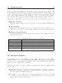
5.4.1.1 Description of Remote Console Options
Ctrl+Alt+Delete
Special button key to send the ‘Control Alt Delete’ key combination to the remote system
(see also Section 5.4.5 on page 35 for defining new button keys).
State line
Shows console and connection state. Normally it displays the size of the remote screen in
pixels. The value in round brackets describes the connection to the remote system: Norm
stands for a standard connection without encryption; SSL stands for a secured connection.
In case there is a connection error, it will be displayed in this line as well. You can double
click the state line in order to see a history of all the state messages.
Auto adjust
Starts the auto adjustment procedure to determine the settings for best visual quality of
the grabbed image. This may take a few moments. During the process the display is
turned off and you will see a notification message.
Sync mouse
Activates the mouse synchronization process. Have a look at Section 5.4.3 on page 31 for
further information about this topic.
Single/Double mouse mode
Switches between the Single Mouse Mode (where only the remote mouse pointer is visible)
and the Double Mouse Mode (where remote and local mouse pointers are visible and need
to be synchronized). Single mouse mode is only available if using SUN JVM 1.3 or higher.
Options
→Exclusive Access
If a user has the appropriate permission, he can force the Remote Consoles of all other
users to close. No one can open the Remote Console at the same time again until this
user disables the exclusive access or logs off.
Options
→Scaling
Allows you to scale down the Remote Console. You can still use mouse and keyboard,
however the scaling algorithm won’t preserve all display details.
Options
→Readability Filter
Toggles the Readability Filter on or off. If the filter is switched on in scaling mode, it will
preserve most of the screen details even if the image is substantially scaled down. This
option will be available only with a Java Virtual Machine version number of 1.3 or higher.
Options
→Chat Window
5.4. REMOTE CONSOLE
29
Opens up the 0801IP/1601IP Chat Frame. See Section 5.4.2 for a detailed description!
Options
→Soft Keyboard
Opens up the Menu for the Soft-Keyboard.
Options
→Soft Keyboard
→Show
Pops up the Soft-Keyboard. The Soft-Keyboard is necessary in case your host system runs
a completely different language and country mapping than your administration machine.
Options
→Soft Keyboard
→Mapping
Used for choosing the according language and country mapping of the Soft-Keyboard.
Options
→Local Keyboard
Used to change the language mapping of your browser machine running the Remote Console Applet. Normally the Applet determines the correct value automatically. However,
depending on your particular JVM and your browser machine settings this is not always
possible. A typical example is a German localized system that uses an US-English keyboard mapping. In this case you have to change the Local Keyboard setting manually to
the right language
Options
→Video Settings
Opens a panel for changing the 0801IP/1601IP video settings. Have a look at Section 5.4.4
on page 32 for a detailed description of the available options.
Options
→Mouse handling
The submenu for mouse handling offers two options for synchronizing the local and the
remote mouse pointer, explained in Section 5.4.3 on page 31. The option for ’Fast Sync’
shows the hotkey in parentheses in case you defined one using the Remote Console Settings.
It is also possible to activate the ’Exclusive Mouse Mode’ (see Section 5.4.5 on page 35
for an explanation).
Options
→Local cursor
Offers a list of different cursor shapes to choose from for the local mouse pointer. The
selected shape will be saved for the current user and activated again next time this user
opens the Remote Console. The number of available shapes depends on the Java Virtual
Machine, only a version of 1.2 or higher offers the full list.
The Remote Console status bar shows some information about the incoming (’In:’) and outgoing
network traffic (’Out:’).
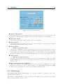
5.4.2 Remote Chat Frame
The 0801IP/1601IP Remote Console features a Chat Frame that allows you to communicate
with other parties logged into the same device. Figure 5.6 on the next page shows an example
30
CHAPTER 5. USAGE
of the Chat Frame.
Figure 5.6: Example for the Chat window
The Chat Frame is helpful especially for discussing problems and questions among logged in
0801IP/1601IP users in case the remote host’s screen should not be changed or misused for that
purpose.
Below all Chat Frame elements are listed together with their meaning and usage. The elements
will be referred to by the terms introduced in Figure 5.6.
Chat Frame element description
Title Bar
Shows the IP address of the 0801IP/1601IP you are connected to.
Chat Area
Read-only text area showing the messages, which have been received so far, inclusive your
own messages sent to others. The identity string of the sender precedes each message.
Identity Label
Shows the identity string used to precede messages sent by this Chat Frame. The first
part of the identity string is the user ID that has been used to log into the client system,
i.e. the system the browser runs on. The second part, behind ‘@’, is the hostname of the
client system. The last part in round brackets is the user name that was used to log into
0801IP/1601IP (‘super’ in the example).
5.4. REMOTE CONSOLE
31
Chat Line
This is an editable text line, where a new message can be entered. Once the Enter key is
hit the message is broadcasted to every other connected party. In case a connected user
has not yet opened the Chat Frame it will be opened automatically in order to deliver the
message.
Note:
Any message sent to the Chat will be broadcasted to ALL connected users, which are using
the Remote Console at the time the message was sent. There is no option to direct a
message to a particular user only.
The Chat has no message history. That means, messages will be received only after opening
the Remote Console. Messages that possibly have been sent among other users will be lost
for a user who opens up his Remote Console afterwards.
5.4.3 0801IP/1601IP Mouse Synchronization
5.4.3.1 Introduction
A common problem with KVM devices is the synchronization between the local and remote
mouse cursors. 0801IP/1601IP addresses this situation with an intelligent synchronization algorithm. There are two mouse modes available on 0801IP/1601IP.
Auto mouse speed
The automatic mouse speed mode tries to detect the speed and acceleration settings of
the host system automatically. See the section below for a more detailed explanation.
Fixed mouse speed
This mode just translates the mouse movements from the Remote Console in a way that
one pixel move will lead to n pixel moves on the remote system. This parameter n
is adjustable with the scaling. It should be noted that this works only when mouse
acceleration is turned off on the remote system.
5.4.3.2 Auto mouse speed and mouse synchronization
The automatic mouse speed mode performs the speed detection during mouse synchronization.
Whenever the mouse doesn’t move correctly, there are two ways for re-synchronizing local and
remote mouse:
Fast Sync
The fast synchronization is used to correct a temporary, but fixed skew. Choose the
option using the Remote Console options menu (see Section 5.4 on page 26) or press the
mouse synchronization hotkey sequence in case you defined one (refer to Section 5.4.5 on
page 35).
Intelligent Sync
If the fast sync doesn’t work or the mouse settings have been changed on the host system,
use the intelligent resynchronization. This method takes more time than the fast one and
can be accessed with the appropriate item in the Remote Console options menu. The
intelligent synchronization requires a correctly adjusted picture. Use the auto adjustment
function or the manual correction in the Video Settings panel (refer to Section 5.4.4 on
the next page) to setup the picture.
32
CHAPTER 5. USAGE
The ’Sync mouse’ button on top of the Remote Console can behave differently, depending on
the current state of mouse synchronization. Usually pressing this button leads to a fast sync,
except in situations where the KVM port or the video mode changed recently.
5.4.3.3 Limitations of the mouse synchronization
While the intelligent algorithm works fine for common cases, there are some special limitations
which may prevent the synchronization from working properly:
Special Mouse Driver
There are mouse drivers, which influence the synchronization process leading to desynchronized mouse pointers. If this happens, make sure you don’t use a special vendor-specific
mouse driver on your host system.
Windows XP Mouse Setting
Windows XP knows a setting to ’improve mouse acceleration’, which has to be deactivated
Badly adjusted picture
To have the intelligent sync working, a correctly adjusted picture is necessary. Use the
auto adjustment function or the manual correction in the Video Settings panel (refer to
Section 5.4.4) to setup the picture. The video also has to be of sufficiently good quality.
Active Desktop
Check if you have the Active Desktop feature of Microsoft Windows enabled. If so, don’t
use a plain background, use some kind of wallpaper. You could also disable the Active
Desktop entirely.
5.4.3.4 Single and Double Mouse Mode
The information above applies to the Double Mouse Mode, where remote and local mouse
pointers are visible and need to by synchronized. 0801IP/1601IP also features another mode,
the Single Mouse Mode, where only the remote mouse pointer is visible. Activate this mode in
the open Remote Console (see Section 5.4 on page 26) and click into the window area. The local
mouse pointer will be hidden and the remote one can be controlled directly. To leave this mode,
it is necessary to define a mouse hotkey in the Remote Console Settings Panel (Section 5.4.5 on
page 35). Press this key to free the captured local mouse pointer.
Single Mouse mode needs at least a Sun Java Virtual Machine 1.3.
5.4.4 0801IP/1601IP Video Settings
0801IP/1601IP features two different dialogs which influence the video settings.
5.4.4.1 Video Settings through the HTML-Frontend
One side is the video options panel in the 0801IP/1601IP HTML-Frontend (see Figure 5.7 on
the next page)
5.4. REMOTE CONSOLE
33
Figure 5.7: Video Settings in HTML frontend
Enable local video port: This option decides if the local video output of 0801IP/1601IP is
active and passing through the incoming signal from the host system.
Noise filter: This option defines how 0801IP/1601IP reacts to small changes in the video input
signal. A large filter setting needs less network traffic and leads to a faster video display, but
small changes in some display regions may not be recognized immediately. A small filter displays
all changes instantly but may lead to a constant amount of network traffic even if display content
is not really changing (depending on the quality of the video input signal). All in all the default
setting should be suitable for most situations.
5.4.4.2 Video Settings through the remote console
0801IP/1601IP features a panel to setup the following video options (see Figure 5.8), available
in the Remote Console Options menu.
Figure 5.8: Video Settings Panel
Brightness
Controls the brightness of the picture
Contrast
Controls the contrast of the picture
Clock
Defines the horizontal frequency for a video line and depends on the video
mode. Different video card types may require different values here. The
default settings in conjunction with the auto adjustment procedure should
be adequate for all common configurations. If the picture quality is still
bad after auto adjustment you may try to change this setting together with
the sampling phase to achieve a better quality.
34
CHAPTER 5. USAGE
Phase
Defines the phase for video sampling, used to control the display quality
together with the setting for sampling clock.
Horizontal Position Use the left and right buttons to move the picture in horizontal direction
while this option is selected
Vertical Position
Use the left and right buttons to move the picture in vertical direction while
this option is selected
Reset this Mode
Resets mode specific settings to their factory defaults
Reset all Modes
Resets all settings to their factory defaults
Save changes
Save changes permanently
Undo changes
Restore last settings
5.4.4.3 Custom Video Modes
Using this option (see Figure 5.9) it is possible to add video modes to 0801IP/1601IP, which
are not recognized using the factory settings. This may be useful when using special modelines
in a X-Window configuration on the host or with uncommon hosts or operating systems.
This option is for advanced users only, it is possible to influence the correct video transmission by using this option, so use it with care!
Figure 5.9: Custom Video Modes
The maximum number of custom video resolutions is 4. Using the option ”‘Custom Modes
Handling”’ custom modes may be disabled (”‘Off”’), used additional to the standard video
resolutions or used exclusive (”‘Only”’). With the last option it is also possible to force a special
video mode for 0801IP/1601IP.
To change the parameters for a mode, choose the number and press ”‘Update”’. It is necessary
to provide some information so the video mode may be correctly recognized:
X Resolution Visible number of horizontal pixels.
Y Resolution Visible number of vertical pixels.
Horizontal Frequency (Hz) The horizontal (line) frequency in Hz.
Vertical Frequency (Hz) The vertical (refresh) frequency in Hz.
5.4. REMOTE CONSOLE
35
Total horizontal pixels The total amount of pixels per line, including the non-visible
and blanking area.
Polarity The polarity (positive/negative) of the synchronization signals. V means vertical, H means horizontal.
Description Here you can provide a mode name which is displayed in the Remote Console
if this custom mode is activated.
5.4.5 Remote Console Settings
The Remote Console settings allow you to customize the Remote Console window prior to its
start. Some of the parameters you might still change while the Remote Console is running while
others have to be set in the Remote Console settings.
All the settings for the Remote Console window are user specific. That means, each user can
individually customize the Remote Console for his needs. Changing the settings for one user
does not affect the settings for others.
Figure 5.10: Example of Remote Console settings
User select box
This control will show the user ID for which the values are shown and for which changes
will take effect. You might change the settings of other users in case you have the necessary
access rights.
36
CHAPTER 5. USAGE
Start in Monitor Mode
Sets the initial value for the monitor mode. By default the monitor mode is off. In case
you switch it on, the Remote Console window will be started in a read only mode.
Exclusive Access
Enables the exclusive access mode immediately at Remote Console startup. This forces
the Remote Consoles of all other users to close. No one can open the Remote Console at
the same time again until this user disables the exclusive access or logs off.
Remote Console Type
Specifies, which Remote Console Viewer to use.
– Default Java-VM
Uses the default Java Virtual Machine of your Browser. This may be the Microsoft
JVM for the Internet Explorer or the Sun JVM if it is configured this way. Use of
the Sun JVM may also be forced (see below).
– Sun Microsystems Java Browser Plugin
Instructs the web browser of your administration system to use the JVM (Java Virtual
Machine) of Sun Microsystems. The JVM in the browser is used to run the code
for the Remote Console window, which is actually a Java Applet. If you check
this box for the first time on your administration system and the appropriate Java
plug-in is not already installed on your system, it will be downloaded and installed
automatically. However, in order to make the installation possible, you still need to
answer the according dialogs with YES. The download volume is around 11 Mbytes.
The advantage of downloading Sun’s JVM lays in providing a stable and identical
Java Virtual Machine across different platforms. The Remote Console software is
optimized for this JVM versions and offers wider range of functionality when run
in SUN’s JVM. (Hint: If you are connected over a slow connection to the Internet
you can also pre-install the JVM on your administration machine. The software is
available on the CD that is delivered along with 0801IP/1601IP.)
– ActiveX control
This option instructs the web browser to use the ActiveX-Control of the KVM Vision
Viewer, an application available separately. You have to install this program on
your local system, please refer to the manual of the KVM vision viewer for further
information. This option only works with Microsoft Internet Explorer on Win32
Systems.
Mouse hotkey
Allows to specify a hotkey combination which starts either the mouse synchronization process if pressed in the Remote Console (see Section 5.4.3 on page 31 for more information)
or is used to leave the single mouse mode. The key codes are listed in Appendix C on
page 69.
Button Keys
Button Keys are meant for simulating keystrokes on the remote system that cannot be
generated locally. The reason for this might be a missing key or the fact, that the local
operating system of the Remote Console is unconditionally catching this keystroke already.
Typical examples are ‘Control Alt Delete’ on Windows and DOS, what is always caught
or ‘Control Backspace’ on Linux for terminating the X-Server. The syntax to define a new
Button Key is as follows:
[conf irm] < keycode > [+| − [∗] < keycode >]∗
5.5. SERVER
37
confirm requests confirmation by a dialog box before the key strokes will be sent.
keycode is the key to be sent. Multiple key codes can be concatenated with a + or a −
sign. The + sign builds key combinations, all keys will be pressed until a − sign or the
end of the combination is encountered. In this case all pressed keys will be released in
reversed sequence. So the − sign builds single, separate keypresses and -releases. The ∗
inserts a pause with a user-definable duration(see Section 5.5.3 on page 39). For a list of
key codes and aliases 0801IP/1601IP recognizes refer to Appendix C on page 69. If you
need more button keys than shown, hit the More entries button.
Pressing the Apply button finally changes the values permanently in 0801IP/1601IP.
5.4.6 Telnet Console
This option offers a Java applet for the Telnet protocol (Figure 5.11) to open a connection to
0801IP/1601IP. Its main use is the passthrough option for the serial port 1 (see also Section 5.6.5
on page 49). The Telnet access has to be enabled in the security settings as well (see Section 5.6.9
on page 53). Of course it is also possible to connect with a standard Telnet client. For details
regarding the Telnet interface please refer to Section 5.7 on page 60.
Figure 5.11: Telnet Console
5.5 Server
5.5.1 Power Control
5.5.1.1 External power option
If Serial Port is set to “External power option” and an external power switch is selected the
Power Control page shows two areas (Figure 5.12 on the following page).
The upper half called “Server Power Control” is used to switch the power for the KVM port
currently active. Use the KVM settings to assign ports of external power switches to a KVM
port. A list of all assigned power ports is shown above the switch buttons. If no assignment
exists, the option is disabled.
The lower half offers controls for switching each port of the external power switch directly.
Select the appropriate port and if there is more than one Smart Start Jr. configured in Serial
Settings select the appropriate device as well. Then decide whether to switch a single port or
all ports of one device as a sequence. The order of the sequence and the delay between two
switched ports are configurable in the Smart Start Jr. setup tool.
Warning: Power ports that are manually switched to “off” state via single port switch can
not be re-activated by using “Sequence On”!
38
CHAPTER 5. USAGE
Figure 5.12: External Power Switch Option
Note: While sequence switch is in progress there are no other actions possible on the power
switch including get state and single port switch. The web frontend will show a notification
in this case.
5.5.1.2 Power Switch Status
If and only if Smart Start Jr. is selected in “External Power Switch Options” (Serial Settings),
there will be a new option in the navigation bar called “Power Switch Status”. Perhaps you
have to reload the navigation bar until the new option is shown.
The “Power Switch Status” page itself shows various information about Voltage, Current, optionally installable temperature probes and the state of switchable external contacts (Figure 5.13
on the next page). If there is more than one Smart Start Jr. configured, you can choose the
currently shown device from the select box on the top of the page.
External contacts can be switched on or off through the frontend. Additionally you can set
these external contacts to monitor several conditions like over voltage etc. This can be done
only with the Smart Start Jr. setup tool or manually with a serial terminal.
5.5.2 Keyboard/Mouse Settings
0801IP/1601IP supports different keyboard and mouse models. The panel shown in Figure 5.14
on page 40 is used to adjust those settings as well as some other ones. Their meaning is listed
below:
5.5. SERVER
39
Figure 5.13: Power Switch Status
Targeted KVM port
Selects the KVM port the settings made below will be applied to. Choosing update will
display the current values for this port and select it for alteration of its settings.
Keyboard Model
Selects the keyboard model used on the remote host system.
Mouse Model
Selects the mouse model that is used on the remote system. A wrongly selected mouse
model may result in strange mouse effects.
Mouse Mode
→Direct (1:n) mouse mode
Use a direct translation of mouse movements between the local and the remote pointer.
You may also set a fixed Scaling which determines the amount the remote mouse pointer
moved when the local mouse pointer is moved by one pixel. This option only works when
the mouse settings on host are linear, means that there is no mouse acceleration involved.
Mouse Mode
→Automatic speed detection
Use this option if the mouse settings on host use an additional acceleration setting.
0801IP/1601IP tries to detect the acceleration and speed of the mouse during the mouse
sync process.
Reset mouse/keyboard emulation
This option will reset the 0801IP/1601IP keyboard and mouse emulation for the host
system. Use it if the keyboard or mouse seems to react irrationally. Its just like pulling
out the keyboard and mouse connectors and plugging them in again.
5.5.3 KVM Settings
The 0801IP/1601IP KVM settings (Figure 5.15 on page 41) allow to setup the ports of the
integrated KVM switch.
It is possible to assign a name to each port and to decide whether to show a button for selecting
this port in the Remote Console or not.
40
CHAPTER 5. USAGE
Figure 5.14: Keyboard/Mouse settings
The ’Switch active port’ option allows to switch the current port of the integrated KVM switch.
It is also possible to do so using the 0801IP/1601IP home page (Section 5.3.2 on page 25).
Note: It is still possible to apply the necessary key combinations for switching KVM
ports through the Remote Console, however, in this case video and mouse synchronization
settings will be shared among the ports and may unintentionally be changed for one of
those ports.
KVM Power Port Assignment It is possible to assign single or multiple power switch ports
to each KVM port. Once the reference between KVM port and power switch ports is made you
can always switch the power state of a KVM port on the “Power Control” page.
Unlike previous 0801IP/1601IP firmware versions this version has a separate page for assigning
power switch ports to KVM ports (Figure 5.16 on page 42). This page can be reached through
the KVM Settings page by clicking on the “Assign” link beneath the KVM Port Settings.
On this page you can select and append several power ports to the list, delete items from the list
or resort the order of the items. Once done all ports from this list can be switched successively
with one click from the “Power Control” page.
5.6. ADMINISTRATION
41
Figure 5.15: KVM Settings
5.6 Administration
5.6.1 User/Group Management
The user and group management of 0801IP/1601IP is based on configurable users and groups.
Each user or group may have different permissions.
Upon delivery, each 0801IP/1601IP is pre-configured with a supervisor user called ‘super’ having
the password 0801ip/1601ip. Make sure to change the super user password immediately after
you have installed and firstly accessed your 0801IP/1601IP.
Figure 5.17 on page 43 shows the User/Group Management panel of the front-end. Its use will
be described in the following text.
Existing user
Select an existing user for modification or deletion. Once a user has been selected, click
the lookup button to see the complete user information.
New user name
In order to create a new user, enter a new login name in this field. The new name must
not yet exist as user or group. In case it does, an error message will be displayed on top
of the panel.
Full user name
This name is the full name belonging to the login name.
Password
The password for the login name. It must be at least four characters long.
Confirm password
Confirmation of the password above.
Email address
This is optional.
42
CHAPTER 5. USAGE
Figure 5.16: Assigning power ports to KVM ports
Mobile number
This information may be optionally provided.
Group membership
Each user can be a member of one or more groups.
Existing groups
Selects an existing group for copying, modification or deletion.
New group name
In order to create a new group, enter a new and unused group name.
The user management of 0801IP/1601IP allows many different users. The following sections
will describe how to add, change and delete users.
5.6.1.1 Add User
Fill out the fields ‘New user name’, ‘Full user name’, ‘Password’ and ‘Confirm password’ as
shown in Figure 5.17 on the next page. Optionally select the groups the new user should
become a member of. Click the ’Create user’ button.
5.6.1.2 Delete User
Select a user in the ‘Existing user’ control. Click the ‘Lookup’ button. The complete user
information will be shown. Click the ‘Delete user’ button.
Hint:
The pre-configured supervisor user ‘super’ can’t be deleted. This user can be renamed only.
5.6. ADMINISTRATION
43
Figure 5.17: User/Group Management
5.6.1.3 Modify User
Select a user in the ‘Existing user’ control. Click the lookup button to get all the user’s information. All fields can be modified as required. The old password is not displayed, but can be
modified. If all changes are done click the ‘Modify user’ button.
5.6.1.4 Copy User
Select a user in the ‘Existing user’ control. Enter a new user name in the field ‘New user name’.
Click the ‘Copy User’ button. This will create a new user with the given name. All properties
of the selected user will be copied to the new one, except user specific permissions.
5.6.1.5 Add Group
Type the name of the new group into the field ‘New group name’ and click the ‘Create group’
button.
5.6.1.6 Delete Group
Select a group in the ‘Existing group’ control. Click the ‘Delete group’ button.
44
CHAPTER 5. USAGE
5.6.1.7 Modify Group
To modify an existing group select the group in the ‘Existing group’ control. The group’s name
field can be modified. Finally click the ‘Modify group’ button.
5.6.1.8 Copy Group
Select a group in the ‘Existing group’ control and type the name of the new group into the field
‘New group name’. Click the ‘Copy Group’ button. This will create a new group and copy all
properties and permissions of the selected group to the newly created group.
5.6.2 User/Group Permissions
A set of permissions is assigned to each user or group. Those rights are used to authorize
access to certain 0801IP/1601IP functionalities for a particular user. By default the user ’super’
has all permissions. His permissions cannot be shrunk. A newly created user or group has no
permissions. A user will inherit the permissions of all groups he belongs to.
Figure 5.18: User/Group Permissions panel
The User/Group Permissions panel as shown in Figure 5.18 allows you to change the permissions
of a certain user or group. The right of one user for changing another user’s or group’s access
rights is determined by the parent/child relationship between them. When one user is creating
another user, he will implicitly become the parent of that new user and hence has the right to
change his permissions. More general, a certain user has the right to change another user’s or
group’s permissions in case he stands higher in the ancestry than the other one. The ’super’
user stands at the top (or the root) of the ancestry, hence has the right to change everybody’s
permissions.
Additionally, there is the restriction that a user can never give more permission to others than
those he has. For example, if a user has no permission to change the network settings he won’t
be able to grant this right to somebody else. However, a user has always the right to reduce
the set of permissions of his descendants.
5.6. ADMINISTRATION
45
In order to change the permissions of a user/group you have to select the user/group first. This
is done using the selection list at the top of the User/Group Permissions panel (see Figure 5.18
on the preceding page). The selection list will show only users and groups for which you have the
right to change their permissions. Next, clicking the ‘Update’ button will show the permission
list of that user. Every right in the list has a permission value, which is explained in Table 5.2.
The displayed columns differ, depending on the user/group selected and the one logged in:
Effective Permission
The final permission which decides if a user may access a specific 0801IP/1601IP function
or not.
User Permission
Permission for the currently selected user/group. If the user selected equals to the one
logged in it is only possible to view the value, otherwise a select box appears to change it.
Inherited Group Permission
Permission value inherited from the groups a user belongs to. This column is not available
while a group is selected.
Field
deny access
allow view
deny change
allow change
allow access
group setting
Table 5.2: 0801IP/1601IP user and group permissions
Description
The user cannot use this function.
The user can view the entry.
The user cannot change the entry’s settings.
The user can change the entry settings.
The user can use this function.
No permission, use the one inherited from the group(s) the
user belongs to. Default is to deny access.
5.6.3 Port Access Permissions
A users ability to look at certain KVM ports may be limited using the port access permission
settings (see Figure 5.19 on the next page). It works similar to the normal User/Group permissions (Section 5.6.2 on the facing page) settings, so most of these instructions also apply here.
Each port uses an ”‘allow access”’ permission.
If the user is not allowed to access a certain port, it influences the behaviour of 0801IP/1601IP
in some ways:
The KVM port switch box on the home page will display the non-accessible ports in red,
the allowed ones in green. It will not be possible to switch to a forbidden port this way.
The same applies to the KVM settings page.
If a switch to a non-accessible port occurs, all users which are not allowed to view this
port will be disconnected. It will not be possible for these users to open a new connection
until an allowed port is activated again.
46
CHAPTER 5. USAGE
Figure 5.19: Port Access Permissions panel
5.6.4 Network Settings
The Network Settings panel as shown in Figure 5.20 on the next page allows changing network
related parameters. Each parameter will be explained below. Once applied the new network
settings will immediately come into effect.
Note:
The initial IP configuration is usually done directly at the host system using the special
procedure described in Section 4.1 on page 15.
Attention:
Changing the network settings of 0801IP/1601IP might result in losing connection to it.
In case you change the settings remotely make sure all the values are correct and you still
have an option to access the 0801IP/1601IP.
IP auto configuration
With this option you can control if 0801IP/1601IP should fetch it’s network settings from
a DHCP or BOOTP server. For DHCP you have to enter dhcp and for BOOTP supply
bootp accordingly. If you specify none then IP auto-configuration is disabled.
IP address
IP address in the usual dot notation.
Subnet mask
The net mask of the local network.
Gateway IP address
In case the 0801IP/1601IP should be accessible from networks other than the local one,
this IP address must be set to the local network router’s IP address.
Primary DNS Server IP address
IP address of the primary Domain Name Server in dot notation. This option may be left
empty, however 0801IP/1601IP won’t be able to perform name resolution.
5.6. ADMINISTRATION
47
Figure 5.20: 0801IP/1601IP network settings
Secondary DNS Server IP address
IP address of the secondary Domain Name Server in dot notation. It will be used in case
the Primary DNS Server can’t be contacted.
Primary Time Server
IP address of the primary NTP (Network Time Protocol) compliant timeserver in dot
notation. 0801IP/1601IP will synchronize its own absolute time with the timeserver’s
one. This is important for writing log entries and for the Dynamic DNS Service.
Secondary Time Server
IP address of the secondary NTP compliant timeserver in dot notation. It will be used in
case the Primary Time Server can’t be contacted.
Remote Console & HTTPS port
Port number at which 0801IP/1601IP’s Remote Console server and HTTPS server are
listening. If left empty the default value will be used.
HTTP port
Port number at which 0801IP/1601IP’s HTTP server is listening. If left empty the default
value will be used.
Telnet port
Port number at which 0801IP/1601IP’s Telnet server is listening. If left empty the default
value will be used.
Bandwidth limitation
The maximum network traffic generated through the 0801IP/1601IP Ethernet device.
Unit is Kbit/s.
Disable Setup Protocol
With this option you may exclude this 0801IP/1601IP from setup protocol.
48
CHAPTER 5. USAGE
5.6.4.1 Dynamic DNS
A freely available Dynamic DNS service (dyndns.org) can be used in the following scenario (see
Figure 5.21):
Figure 5.21: Dynamic DNS Scenario
0801IP/1601IP is reachable via the IP address of the DSL router, which is dynamically assigned
by the provider. Since the administrator doesn’t know the IP address assigned by the provider,
0801IP/1601IP connects to a special dynamic DNS server in regular intervals and registers its
IP address there. The administrator may contact this server as well and pick up the same IP
address belonging to his card.
The administrator has to register a 0801IP/1601IP that is supposed to take part in the service
with the Dynamic DNS Server and assign a certain hostname to it. He will get a nickname and
a password in return to the registration process. This account information together with the
hostname is needed in order to determine the IP address of the registered 0801IP/1601IP.
Figure 5.22: Dynamic DNS configuration panel
You have to perform the following steps in order to enable Dynamic DNS:
1. Make sure the LAN interface of 0801IP/1601IP is properly configured.
2. Enter the Dynamic DNS Settings configuration dialog as shown in Figure 5.22 (Menu →
Network Settings → Dynamic DNS Settings)
3. Enable Dynamic DNS and change the settings according to your needs (see below).
Enable Dynamic DNS
This enables the Dynamic DNS service. This requires a configured DNS server IP address.
5.6. ADMINISTRATION
49
Dynamic DNS server
This is the server name where 0801IP/1601IP registers itself in regular intervals. Currently
this is a fixed setting since only dyndns.org is supported for now.
Hostname
This is the hostname of 0801IP/1601IP, provided by the Dynamic DNS Server. (use
the whole name including the domain, e.g. testserver.dyndns.org, not just the actual
hostname)
Username
You have registered this username during your manual registration with the Dynamic
DNS Server. Spaces are not allowed in the Nickname!
Password
You have used this password during your manual registration with the Dynamic DNS
Server. Spaces are not allowed in the Nickname!
Check time
0801IP/1601IP card registers itself in the Dynamic DNS server at this time.
Check interval
This is the interval for reporting again to the Dynamic DNS server by 0801IP/1601IP.
Note:
0801IP/1601IP has its own independent real time clock. Make sure the time setting of
0801IP/1601IP is correct. This can be achieved by configuring a timeserver (see Figure 5.20
on page 47)
5.6.5 Serial Settings
The 0801IP/1601IP Serial Settings (Figure 5.23 on the following page) allow you to specify,
what device is connected to the serial port and how to use it.
Configuration login
Don’t use the serial port for any special function, use it only for the initial configuration
(see Section 4.1 on page 15).
Modem
Allows to access 0801IP/1601IP via modem, see Section 5.6.7 on the following page for
details.
Passthrough
Using this option, it is possible to connect an arbitrary device to the serial port and access
it (assuming it provides terminal support) via Telnet. Select the appropriate options for
the serial port and use the Telnet Console (see Section 5.4.6 on page 37) or a standard
Telnet client to connect to 0801IP/1601IP. For more information about the Telnet interface
have a look at Section 5.7 on page 60.
External power option
This serial port provides the power control options for 0801IP/1601IP (see also Section 5.5.1 on page 37).
50
CHAPTER 5. USAGE
Figure 5.23: Serial Settings
5.6.6 External Power Options
Choose a suitable setting and fill in additional required options. By the date of printing this
manual 0801IP/1601IP supports the following options
ePowerSwitch - Slave
The ePowerSwitch-S is a cascade of up to 4 power sockets with 8 ports. 0801IP/1601IP
has to be connected to the first socket of the cascade via a serial connection.
Smart Start Jr.
The Smart Start Jr. is a cascade of up to 8 power sockets with 8 ports. 0801IP/1601IP
has to be connected to the first socket of the cascade via a serial connection.
Figure 5.24: External Power Option Settings
5.6.7 Modem Settings
0801IP/1601IP offers remote access using a telephone line in addition to the standard access
over the built-in Ethernet adapter. The modem needs to be connected to the serial interface of
5.6. ADMINISTRATION
51
0801IP/1601IP.
Logically, connecting to 0801IP/1601IP using a telephone line means nothing else than building
up a dedicated point to point connection from your console computer to the 0801IP/1601IP.
With other words, 0801IP/1601IP acts as an Internet Service Provider (ISP) to which you
can dial in. The connection is established using the Point-to-Point Protocol (PPP). Before
you connect to 0801IP/1601IP, make sure to configure your console computer accordingly. For
instance on Windows based operating systems you can configure a dial-up network connection,
which defaults to the right settings like PPP.
The Modem Settings panel allows you to configure the remote access to 0801IP/1601IP using a
modem. The meaning of each parameter will be described below. The modem settings are part
of the serial settings panel (Figure 5.23 on the facing page).
Serial line speed
The speed 0801IP/1601IP is communicating with the modem. Most of all modems available today will support the default value of 115200 bps. In case you are using an old
modem and discovering problems try to lower this speed.
Modem Init String
The initialization string used by 0801IP/1601IP to initialize the modem. The default value
will work with all modern standard modems directly connected to a telephone line. In
case you have a special modem or the modem is connected to a local telephone switch that
requires a special dial sequence in order to establish a connection to the public telephone
network, you can change this setting by giving a new string. Refer to the modem’s manual
about the AT command syntax.
Modem server IP address
This IP address will be assigned to the 0801IP/1601IP itself during the PPP handshake.
Since it is a point-to-point IP connection virtually every IP address is possible but you
must make sure, it is not interfering with the IP settings of 0801IP/1601IP and your
console computer. The default value will work in most cases.
Modem client IP address
This IP address will be assigned to your console computer during the PPP handshake.
Since it is a point-to-point IP connection virtually every IP address is possible but you
must make sure, it is not interfering with the IP settings of 0801IP/1601IP and your
console computer. The default value will work in most cases.
5.6.8 Authentication Settings
With 0801IP/1601IP you have the possibility to keep authentication information in a central
LDAP directory or a RADIUS server. Generally only authentication information are handled
by this central server, all authorization information is handled by 0801IP/1601IP itself which
means that all user accounts must exist twice: one on 0801IP/1601IP side with all permission
data and one on the central server which only requires a user name and a password. The user
name of these two accounts has to be identical.
If you want to use LDAP or RADIUS for authentication purposes you have to specify some
information in the Authentication settings panel (Figure 5.25). You can choose between local,
Figure 5.25: Authentication settings panel
52
CHAPTER 5. USAGE
LDAP and RADIUS authentication. For more information regarding the LDAP and RADIUS
settings see below.
5.6.8.1 LDAP
User LDAP Server
Here you enter the name or IP address of the LDAP server containing all the user entries.
If you choose a name instead of an IP address you need to configure a DNS server in the
network settings.
Base DN of User LDAP Server
Here you specify the distinguished name (DN) where the directory tree starts in the user
LDAP server.
Type of external LDAP Server
With this option you set the type of the external LDAP server. This is necessary since
some server types require special handling. Additionally the default values for the LDAP
schema are set appropriately. You can choose between Generic LDAP Server, Novell
Directory Service and Microsoft Active Directory. If you have neither Novell Directory
Service nor Microsoft Active Directory then choose Generic LDAP Server and edit the
LDAP schema used (see below).
Name of login-name attribute
This is the name of the attribute containing the unique login name of a user. To use the
default leave this field empty. The default depends on the selected LDAP server type.
Name of user-entry object class
This is the object class that identifies a user in the LDAP directory. To use the default
leave this field empty. The default depends on the selected LDAP server type.
User search subfilter
Here you can refine the search for users that should be known to the 0801IP/1601IP.
Active Directory Domain
This option represents the active directory domain that is configured in the Microsoft
Active Directory server. This option is only valid if you have chosen Microsoft Active
Directory as the LDAP server type.
5.6.8.2 RADIUS
RADIUS authentication may use up to 10 servers in case that one or more of them are down
or not reachable. If no server is reachable you will get an ”Authentication failed” message at
log-in even if user name and password are valid.
Server
The Server text field is either an IP address or, in case that a valid DNS server is set in
”Network Settings”, a server name. This field is mandatory.
Shared Secret
The Shared Secret is a text string which is comparable with a server password. This
Shared Secret is optionally configured on the RADIUS servers and has a maximum length
of 128 characters.
5.6. ADMINISTRATION
53
Auth. Port
The port for authentication requests. These type of requests are performed if a user tries
to login or logout. The port for this request is by default 1812 and normally there is no
reason to change it on the server. If you leave this field blank the default value will be
used.
Acc. Port
The port for accounting requests which is only needed on 0801IP/1601IP to write authentication data to the servers log file. The default value for this port is 1813 and it will be
used if the Acc. Port text field is left blank.
Timeout
The timeout in seconds for each request.
Retries
The number of retries for each request and server. (i.e. if you have specified all 10 servers
and each with 3 retries then there are up to 30 requests until authentication succeeds or
fails )
More servers
If this button was clicked the page reloads with more table rows to enter up to 10 RADIUS
servers.
5.6.9 Security Settings
Figure 5.26 shows the panel for security related SSL, Telnet and IP address settings. Each of
those categories will be explained in the following subsections.
Figure 5.26: Security settings
54
CHAPTER 5. USAGE
5.6.9.1 SSL Settings
The following section explains the possible adjustments related to the usage of SSL.
Force HTTPS
If this option is enabled access to the web front-end is only possible using an HTTPS
connection. 0801IP/1601IP won’t listen on the HTTP port for incoming connections.
In case you want to create your own SSL certificate that is used to identify this 0801IP/1601IP
refer to Section 5.6.10 on page 56.
KVM encryption
This option controls the encryption of the RFB protocol, the protocol used by the Remote
Console to transmit the screen data to the administrator machine and keyboard and mouse
data back to the host.
If set to ‘Off’ no encryption will be used.
If set to ‘Try’ the applet tries to make an encrypted connection. In case connection
establishment fails for any reason an unencrypted connection will be used.
If set to ‘Force’ the applet tries to make an encrypted connection. An error will be reported
in case connection establishment fails.
5.6.9.2 Telnet Settings
Enable Telnet access
If this option is enabled, access over Telnet client is possible. For higher security we
recommend to disable Telnet access.
5.6.9.3 IP Access Control
This section explains the settings related to IP access control. It is used to limit access to a
distinguished number of clients only. These clients will be identified by their IP address, from
which they are trying to build up a connection. Refer also to Figure 5.26 on the preceding page.
Note:
The IP access control settings apply to the LAN interface only!
Enable IP Access Control
Enables access control based on IP source addresses.
Default policy
This option controls what to do with arriving IP packets that don’t match any of the
configured rules. They can be accepted or dropped.
ATTENTION:
If you set this to DROP and you have no ACCEPT rules configured, access to the web
front-end over LAN is actually disabled! To enable access again you can change the security settings via modem or by temporarily disabling IP access control with the initial
configuration procedure (see Section 4.1 on page 15).
5.6. ADMINISTRATION
55
Rule Number
This should contain the number of a rule for which the following commands will apply.
This field will be ignored, in case of appending a new rule.
IP/Mask
Specifies the IP address or IP address range for which the rule applies.
Examples (the number concatenated to an IP address with a ‘/’ is the number of valid
bits that will be used of the given IP address):
192.168.1.22/32 matches the IP Address 192.168.1.22
192.168.1.0/24 matches all IP packets with source addresses from 192.168.1.0 to 192.168.1.255
0.0.0.0/0 matches any IP packet
Policy
The policy determines what to do with matching packets. They can be accepted or
dropped.
Note:
The order of the rules is important. The rules are checked in ascending order until a rule
matches. All the rules below the matching one will be ignored. The default policy applies
if no match has been found.
Appending a rule
Enter the IP/Mask and set the policy. Finally, press ‘Append’.
Inserting a rule
Enter the rule number, the IP/Mask and set the policy. Finally, press ‘Insert’.
Replacing a rule
Enter the rule number, the IP/Mask and set the policy. Finally, press ‘Replace’.
Deleting a rule
Enter the rule number and press ‘Delete’.
5.6.9.4 Anti Brute Force Setting
The Anti Brute Force user blocking mechanism allows to disable the login of a certain user if
his password was entered incorrectly a specific number of times. The duration of the blocking
is also configurable.
Max. number of failed logins
Enter the maximum number of failed login attempts after which it should not be possible
for this user to login anymore. Leave this field empty to deactivate the user blocking
feature.
Block time
The number of minutes the user is blocked after he exceeded his maximum number of
failed login attempts. Leave this field empty to block him for an infinite amount of time
until he is manually unblocked again.
56
CHAPTER 5. USAGE
Unblocking users There are two possibilities to unblock a blocked user. A parent user may
go to the user management settings (Section 5.6.1 on page 41) and press the unblock button for
the user.
It is also possible to use the serial console as for the initial configuration (see Section 4.1 on
page 15) and login as ’unblock’. 0801IP/1601IP will ask for the superuser password and present
a list of blocked users which may be unblocked.
5.6.10 SSL Certificate Management
0801IP/1601IP uses the SSL4 protocol for any encrypted network traffic between itself and a
connected client. During connection establishment 0801IP/1601IP has to expose its identity to a
client using a cryptographic certificate. Upon delivery, this certificate and the underlying secret
key is the same for all 0801IP/1601IPs ever produced and certainly won’t match the network
configuration that will be applied to the devices by its user. The certificate’s underlying secret
key is also used for securing the SSL handshake. Hence, this is a security risk (but far better
than no encryption at all).
However, it is possible to generate and install a new certificate that is unique for a particular
device. In order to do that, 0801IP/1601IP is able to generate a new cryptographic key and
the associated so called Certificate Signing Request that needs to be certified by a so called
certification authority (CA). A certification authority verifies that you are who you claim you
are and signs and issues a SSL certificate to you.
The following steps are necessary to create and install a 0801IP/1601IP SSL certificate:
1. Create a SSL Certificate Signing Request using the panel shown in Figure 5.27 on the
facing page (Security Settings → SSL Settings → Create your own SSL certificate). You
need to fill out a number of fields that are explained below. Once this is done, click
‘Create CSR’ which will initiate the Certificate Signing Request generation. The CSR
can be downloaded to your administration machine with the ‘Download CSR’ button (see
Figure 5.28 on page 58).
2. Send the saved CSR to a CA for certification. You will get the new certificate from the
CA after a more or less complicated traditional authentication process (depending on the
CA).
3. Upload the certificate to 0801IP/1601IP using the ‘Upload’ panel as shown in Figure 5.28
on page 58.
After completing these three steps, 0801IP/1601IP has its own certificate that is used for identifying the device to its clients.
Important Note:
If you destroy the CSR on 0801IP/1601IP there is no way to get it back! In case you
deleted it by mistake, you have to repeat the three steps.
In the following the various options of the dialogs are described:
Common name
This is the network name of 0801IP/1601IP once it is installed in the user’s network
(usually the fully qualified domain name). It is identical to the name that is used to
access the device with a web browser (without the ‘http://’ prefix). In case the name
4
SSL — Secure Socket Layer
5.6. ADMINISTRATION
57
Figure 5.27: SSL Certificate Signing Request
given here and the actual network name differ, the browser will pop up a security warning
when the device is accessed over HTTPS.
Organizational unit
This field is used for specifying to which department within an organization 0801IP/1601IP
belongs.
Organization
The name of the organization to which 0801IP/1601IP belongs.
Locality/City
The city where the organization is located.
State/Province
The state or province where the organization is located.
Country
The country where the organization is located. This is the two-letter ISO code, e.g. DE
for Germany or US for the USA.
Challenge Password
Some certification authorities require a challenge password to authorize later changes on
the certificate (e.g. revocation of the certificate). The minimal length of this password is
4 characters.
Confirm Challenge Password
Confirmation of the Challenge Password
Email
The email address of a security contact person that is responsible for 0801IP/1601IP.
Key length
This is the length of the generated key in bits. 1024 Bits are supposed be sufficient for
most cases. Larger keys may result in slower response time of 0801IP/1601IP during
58
CHAPTER 5. USAGE
connection establishment.
Figure 5.28: SSL Certificate Upload
5.6.11 Maintenance
5.6.11.1 Maintenance Features
Figure 5.29: Maintenance
0801IP/1601IP Board Summary This section contains a summary with various information
about this 0801IP/1601IP and its current firmware and allows you to reset the device. Have a
look at Figure 5.29 for an example.
Data file for support This link allows you to download the 0801IP/1601IP data file with
support information. This is an XML file with certain customized support information like the
5.6. ADMINISTRATION
59
serial number etc. You may send this information along together with a support request. It
will help us troubleshooting your problem.
Reset Functions This section allows you to reset specific parts of the device. Currently this involves the video engine and the 0801IP/1601IP itself. Resetting the card itself is mainly needed
to activate a newly updated firmware. It will close all current connections to the administration
console and to the Remote Console. The whole process will take about half a minute. Resetting sub-devices (e.g. video engine) will take some seconds only and do not result in closing
connections.
5.6.11.2 Update Firmware
0801IP/1601IP is a complete standalone computer. The software it runs is called the firmware.
The firmware of 0801IP/1601IP can be updated remotely in order to install new functionality
or special features.
A new firmware update is a binary file which will be sent to you by email or which you can
download from the Peppercon web site. If the firmware file is compressed (file suffix .zip) then
you must unzip it before you can proceed. Under the Windows operating system you may
use WinZip from http://www.winzip.com/ for decompression. Other operating systems might
provide a program called unzip.
Before you can start updating the firmware of your 0801IP/1601IP the new uncompressed
firmware file must be accessible on the system that you use for connecting to 0801IP/1601IP.
Updating the firmware is a three-stage process:
Firstly the new firmware file is uploaded onto 0801IP/1601IP. In order to do that you need
to select the file on your local system using the Browse button of the Upload Firmware
panel (see Figure 5.30). Once the firmware file has been uploaded, it is checked whether
it is a valid firmware file and whether there were any transmission errors. In case of any
error the Upload Firmware function will be aborted.
Figure 5.30: Panel for uploading a new firmware
Secondly, if everything went well, you see the Update Firmware panel (see Figure 5.31 on
the next page). The panel shows you the version number of the currently running firmware
and the version number of the uploaded firmware. Pressing the update button will store
the new version over the old one. Attention: this process is not reversible and might take
some minutes. Make sure the 0801IP/1601IP’s power supply won’t be interrupted during
the update process, because this may cause an unusable device.
Thirdly, after the firmware has been stored, the panel will request you to reset 0801IP/1601IP
manually. Half a minute after the reset, 0801IP/1601IP will run with the new firmware
version and should be accessible. However, you are requested to login once again.
60
CHAPTER 5. USAGE
Figure 5.31: Panel to update a new firmware that was previously uploaded
Attention:
The three-stage firmware update process and complete consistency check are making a mistake in updating the firmware almost impossible. However, only experienced staff members
or administrators should perform a firmware update. Make sure 0801IP/1601IP’s power
supply won’t be interrupted!
5.7 Access via Telnet
The 0801IP/1601IP firmware features a Telnet server that enables a user to connect via a
standard Telnet client. It is used for passthrough access to a device possibly connected to the
serial port 1. This means you may connect any serial device which offers terminal access via
its serial port to 0801IP/1601IP and access it using the Telnet interface. Set the serial settings
(see Section 5.6.5 on page 49) according to the requirements of the device.
Connecting to 0801IP/1601IP is done as usual and as required by the Telnet client, for instance
in a UNIX shell:
telnet 192.168.1.225
This will prompt for username and password in order to log into the device. The credentials
that need to be entered for authentication are identical to those of the web interface. That
means, the user management of the Telnet interface is entirely controlled with the according
functions of the web interface.
Once you have successfully logged in 0801IP/1601IP will present you the command line where
you can enter according management commands.
In general, the Telnet interface supports two operation modes: the command line mode and
the terminal mode. The command line mode is used to control or display some parameters. In
terminal mode the pass-through access to serial port 1 is activated (if the serial settings were
made accordingly). All inputs are redirected to the device on serial port 1 and its answers are
displayed at the Telnet interface.
The following list shows the according command mode command syntax and their usage.
help
Shows the list of the following commands
cls
Clear screen
5
The IP address has to be replaced by the one that is actually assigned to 0801IP/1601IP.
5.7. ACCESS VIA TELNET
61
logout
Logs out the current user and disconnects from the client
version
Shows a compound string off all available version numbers
terminal
Starts the terminal passthrough mode for serial port . The key sequence ‘<esc> exit’
switches back to command mode.
62
CHAPTER 5. USAGE
6 Frequently Asked Questions
Q 001:
A 001:
The remote mouse doesn’t work or is not synchronous.
Make sure the mouse settings in 0801IP/1601IP match the mouse model. There
are some circumstances where the mouse synchronization process could behave
incorrectly, refer to Section 5.4.3 on page 31 for further explanation.
Q 002:
A 002:
The video quality is bad or the picture is grainy.
Try to correct the brightess and contrast settings (see Section 5.4.4 on page 32) until
they are out of a range where the picture looks grainy. Use the auto adjustment
feature to correct a flickering video.
Q 003:
A 003:
Login on 0801IP/1601IP fails.
Was the correct combination of user and password given? On delivery, the user
super has the password 0801ip/1601ip depending on the actual device. Moreover
your browser must be configured to accept cookies.
Q 004:
A 004:
The Remote Console window can’t connect to 0801IP/1601IP.
Possibly a firewall prevents access to the Remote Console. Make sure the TCP
port numbers 443 and 80 are open for incoming TCP connection establishments.
Q 005:
A 005:
No connection can be established to 0801IP/1601IP.
Check whether the network connection is working in general (ping the IP address
of 0801IP/1601IP). If not, check network hardware. Is 0801IP/1601IP powered on?
Check whether the IP address of 0801IP/1601IP and all other IP related settings
are correct! Also verify that all the IP infrastructure of your LAN, like routers etc.,
are correctly configured. Without a ping functioning, 0801IP/1601IP can’t work
either.
Q 006:
Special key combinations, e.g. ALT+F2, ALT+F3 are intercepted by
the console system and not transmitted to the host.
You have to define a so-called ’Button Key’. This can be done in the Remote
Console settings.
A 006:
Q 007:
A 007:
In the browser the 0801IP/1601IP pages are inconsistent or chaotic.
Make sure your browser cache settings are feasible. Especially make sure the cache
settings are not set to something like ”never check for newer pages”. Otherwise
0801IP/1601IP pages may be loaded from your browser cache and not from the
card.
Q 008:
A 008:
Windows XP doesn’t awake from standby mode
This is possibly a Windows XP problem. Try not to move the mouse while XP
goes in standby mode.
64
CHAPTER 6. FREQUENTLY ASKED QUESTIONS
Q 009:
A 009:
Using MacOS X a HTTPS connection fails
You have to install the Peppercon certificate using our certificate installer, available
on the utility CD. Please refer to the instructions on this CD for further information
how to install the certificate.
Q 010:
A 010:
Can’t upload the signed certificate in MacOS X
If an ’internal error’ occurs while uploading the signed certificate either change
the extension of the file to .txt or add a file helper using the Internet Explorer
preferences for this type of file. Make sure that the encoding is plain text and the
checkbox ’use for outgoing’ is checked. Another possibility is to use a Mozilla based
browser.
Q 011:
Everytime I open a dialog box with some buttons the mouse pointers
are not synchronous anymore
Please check, if you have an option like Automatically move mouse pointer to the
default button of dialog boxes enabled in the mouse settings of the operating system.
This option needs to be disabled.
A 011:
Q 012:
A 012:
Remote Console doesn’t open with Opera in Linux
Some versions of Opera don’t grant enough permissions if the signature of the
applet can’t be verified. You can add the lines
grant codeBase "nn.pp.rc.RemoteConsoleApplet" {
permission java.lang.RuntimePermission "accessClassInPackage.sun.*";
};
to the java policy file of opera (e.g. /usr/share/opera/java/opera.policy) to solve
the problem.
A Glossary
ACPI
A specification that enables the operating system to implement power management
and system configuration.
ATX
Advanced Technology Extended: A particular specification of a motherboard introduced by Intel in 1995.
DHCP
Dynamic Host Configuration Protocol: protocol for dynamically assigning IP configurations in local networks.
DNS
Domain Name System: protocol used to locate computers on the Internet by their
name.
FAQ
Frequently Asked Questions
HTTP
Hypertext Transfer Protocol: the protocol used between web browsers and servers.
HTTPS Hyper Text Transfer Protocol Secure: secure version of HTTP.
LED
Light Emitting Diode
PS/2
The PS/2 device interface was developed by IBM and is used by many mice and
keyboards.
SNMP
Simple Network Management Protocol: a widely used network monitoring and control
protocol.
SSL
Secure Socket Layer: encryption technology for the Internet used to provide secured
data transmissions.
SVGA
Super VGA: A refinement of Video Graphics Array (VGA) that provides increased
pitch and resolution performance.
UTP
Unshielded Twisted Pair: a cable with two conductors twisted as a pair and bundled
within the same outer PVC covering.
66
APPENDIX A. GLOSSARY
B 0801IP/1601IP Video Modes
Table B.1 lists the video modes 0801IP/1601IP supports. Please don’t use other custom video
settings besides of these. If done so, 0801IP/1601IP may not be able to detect them.
Table B.1: 0801IP/1601IP Video Modes
Resolution (x,y)
640x350
640x400
640x480
720x400
800x600
832x624
1024x768
1152x864
1152x870
1152x900
1280x960
1280x1024
Refresh Rates (Hz)
70, 85
56, 70, 85
60, 67, 72, 75, 85, 90, 100, 120
70, 85
56, 60, 70, 72, 75, 85, 90, 100
75
60, 70, 72, 75, 85, 90, 100
75
75
66
60
60, 75
68
APPENDIX B. 0801IP/1601IP VIDEO MODES
C Key Codes
Table C.1 shows the key codes used to defines key strokes or hotkeys for several functions.
Please note that these key codes do not represent necessarily key characters that are used on
international keyboards. They name a key on a standard 104 key PC keyboard with an US
English language mapping. The layout for this keyboard is shown in Figure C.1. However, most
modifier keys and other alphanumeric keys used for hotkey purposes in application programs
are on an identical position, no matter what language mapping you are using. Some of the keys
have aliases also, means they can be named by 2 key codes (separated by comma in the table).
Esc
~
F1 F2 F3 F4
1
tab
q
2
3
4
5
6
w
e
r
t
y
Caps a
LShift
F5 F6 F7 F8
s
z
d
x
Lctrl Win Alt
f
c
g
v
7
8
u
h
b
Space
i
j
n
9
F9 F10 F11 F12 Prnt Scrl Brk
0
o
k
m
p
l
,
−
=
[
;
.
AltGR
]
’
?
Bsp
\
Ins Pos1Pgup Num /
*
Del End Pgdn
CR
Rshift
Menu RCtrl
Up
7
8
9
4
5
6
1
2
3
Key (and aliases)
0-9
A-Z
, TILDE
-, MINUS
=, EQUALS
;
’
<, LESS
,
.
/, SLASH
BACK SPACE
TAB
[
]
ENTER
CAPS LOCK
\, BACK SLASH
LSHIFT, SHIFT
Continued on next page
+
CR
Left
Down Right
0
Figure C.1: English (US) Keyboard Layout, used for key codes
Table C.1: Key Names
−
,
70
APPENDIX C. KEY CODES
Table C.1 – continued from previous page
Key (and aliases)
RCTRL
RSHIFT
LCTRL, CTRL
LALT, ALT
SPACE
ALTGR
ESCAPE, ESC
F1
F2
F3
F4
F5
F6
F7
F8
F9
F10
F11
F12
PRINTSCREEN
SCROLL LOCK
BREAK
INSERT
HOME
PAGE UP
DELETE
END
PAGE DOWN
UP
LEFT
DOWN
RIGHT
NUM LOCK
NUMPAD0
NUMPAD1
NUMPAD2
NUMPAD3
NUMPAD4
NUMPAD5
NUMPAD6
NUMPAD7
NUMPAD8
NUMPAD9
NUMPADPLUS,NUMPAD PLUS
NUMPAD/
NUMPADMUL,NUMPAD MUL
NUMPADMINUS,NUMPAD MINUS
NUMPADENTER
WINDOWS
MENU
D Pin Assignments
D.1 VGA HD-15
5
4
10 9
3
2
8
1
7
6
15 14 13 12 11
Pin
1
2
3
4
5
6
7
8
Assignment
Red
Green
Blue
Not connected
GND
GND red
GND green
GND blue
Pin
9
10
11
12
13
14
15
Assignment
5V
GND sync
Not connected
SDA, DDC, ...
HSYNC
VSYNC
DATA CLOCK
Pin
1
2
3
4
Assignment
TX +
TX RX +
Not connected
Pin
5
6
7
8
Assignment
Not connected
RX Not connected
Not connected
Pin
1
2
3
4
Assignment
Not connected
Not connected
TX +
RX +
Pin
5
6
7
8
Assignment
RX TX Not connected
Not connected
D.2 RJ 45 Connector Ethernet
1
2
3
4
5
6
7
8
D.3 RJ 45 Connector ISDN
1
2
3
4
5
6
7
8
72
APPENDIX D. PIN ASSIGNMENTS
D.4 Serial SUB-D 9 Connector 1
1
2
6
3
7
4
8
5
9
Pin
1
2
3
4
5
Assignment
DCD
RX
TX
DTR
GND
Pin
6
7
8
9
Assignment
DSR
RTS
CTS
RI
Pin
1
2
3
4
5
6
7
8
Assignment
VGA Red
VGA Green
VGA Blue
KBD Data
KBD Clock
GND
GND
GND
Pin
9
10
11
12
13
14
15
Assignment
MS Data
KBD VCC
MS Clock
SDA, DCC, ...
HSYNC
VSYNC
DATA CLOCK
D.5 KVM 15 pin connector
5
4
10 9
3
2
8
1
7
15 14 13 12 11
6
E Peppercon Warranty information
LIMITED WARRANTY
Peppercon AG (”Peppercon”) manufactures its hardware products from parts and components
that are new or equivalent to new in accordance with industry-standard practices. Peppercon
warrants that the hardware products including the firmware will be free from defects in materials and workmanship under normal use. Any implied warranties on the Peppercon firmware
and hardware are limited to 24 months, respectively, beginning on the date of invoice. Some
states/jurisdictions do not allow limitations on duration of an implied warranty, so the above
limitation may not apply to you. Additional Peppercon AG grants a special warranty for 6
month.
CUSTOMER REMEDIES
Peppercon’s entire liability and exclusive remedy shall be, at Peppercon’s option, either (a)
return of the price paid, or (b) repair or replacement of the firmware or hardware that does not
meet this Limited Warranty and which is returned to Peppercon with a copy of your receipt.
Damage due to shipping the products to you is covered under this warranty. Otherwise warranty
does not cover damage due to external causes, including accident, abuse, misuse, problems with
electrical power, servicing not authorized by Peppercon, usage not in accordance with product
instructions, failure to perform required preventive maintenance and problems caused by use of
parts and components not supplied by Peppercon. Any replacement hardware will be warranted
for the remainder of the original period or thirty (30) days, whichever is longer.
Peppercon will repair or replace products returned to Peppercon’s facility. To request warranty
service you must inform Peppercon within the warranty period. If warranty service is required,
Peppercon will issue a Return Material Authorization Number. You must ship the products
back to Peppercon in their original or an equivalent packaging, prepay shipping charges, and
insure the shipment or accept the possibility of loss or damage during shipment.
NO OTHER WARRANTIES
To the maximum extend permitted by applicable law, Peppercon disclaim all other warranties,
either express or implied, including, but not limited to implied warranties of merchantability
and fitness for a particular purpose, with regard to the firmware, the accompanying written
materials, and any accompanying hardware. This limited warranty gives you specific legal
rights. You may have others, which vary from state/jurisdiction to state/jurisdiction.
NO LIABILITY FOR CONSEQUENTIAL DAMAGES
To the maximum extent permitted by applicable law, in no event shall Peppercon be liable
for any damages whatsoever (including without limitation, special, incidental, consequential or
74
APPENDIX E. PEPPERCON WARRANTY INFORMATION
indirect damages for personal injury, loss of business information, or any other pecuniary loss)
arising out of the use of or inability to use this product, even if Peppercon has been advised
of the possibility of such damages. In any case, Peppercon entire liability under any provision
of this agreement shall be limited to the amount actually paid by you for the firmware and/or
hardware. Because some states/jurisdictions do not allow the exclusion or limitation of liability
for consequential or incidental damages, the above limitation may not apply to you.
F Specifications
F.1 Size and Weight
Height:
Width:
Length (Box):
Weigth:
44 mm
215 mm
405 mm
3500 g
F.2 Environmental
Temperature
Operating
Storage
Humidity
Operating
Storage
0°C to 40°C (32°F to 131°F)
-18°C to 70°C (-20°F to 158°F)
10% to 90% (non-condensing)
5% to 95% (non-condensing)
76
APPENDIX F. SPECIFICATIONS
G Operation advices
This device has to be operated with the provided power supply ’PEPPERCON UP0451E12P’ only. Use of other power supplies voids the product liability of the manufacturer. If
the power supply shows a malfunction, it must not be opened. Instead a replacement has
to be requested from the manufacturer or the vender.
The power cord of the power supply is the point of junction to the supply network AC
230 V. Therefore the power supply and socket have to be easily accessible to disconnect
them quickly if it is necessary.
The device contains a lithium battery CR 1632. Gladly we exchange this battery for you.
When changing the battery yourself, please notice: ’Attention, explosion hazard while
exchanging the battery improperly. Disposal of old batteries has to be done as mentioned
on the package of the new one.’
78
APPENDIX G. OPERATION ADVICES