1
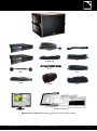
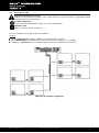
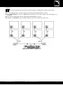
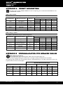
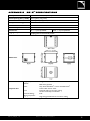
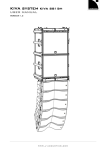
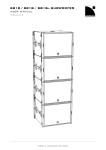
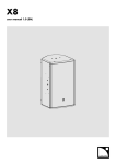
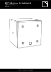
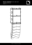
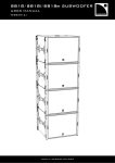
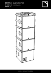
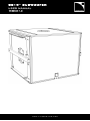
SB15m SUBWOOFER USER MANUAL VERSION 1.0 www.l-acoustics.com SB15m SUBWOOFER user manual VERSION 1.0 SAFETY INSTRUCTIONS 1. Read this manual 2. Follow all SAFETY INSTRUCTIONS as well as DANGER and OBLIGATION warnings 3. Never incorporate equipment or accessories not approved by L-ACOUSTICS® 4. Read all the related PRODUCT INFORMATION documents before exploiting the system The product information document is included in the shipping carton of the related system component. 5. Read the RIGGING MANUAL before installing the system Use the rigging accessories described in the rigging manual and follow the associated procedures 6. Beware of sound levels Do not stay within close proximity of loudspeakers in operation and consider wearing earplugs. Loudspeaker systems are capable of producing very high sound pressure levels (SPL) which can instantaneously lead to permanent hearing damage to performers, production crew and audience members. Hearing damage can also occur with prolonged exposure to sound: 8 h at 90 dB(A), 30 min at 110 dB(A), less than 4 min at 130 dB(A). SYMBOLS The following symbols are used in this document: DANGER This symbol indicates a potential risk of harm to an individual or damage to the product. It can also notify the user about instructions that must be strictly followed to ensure safe installation or operation of the product. OBLIGATION This symbol notifies the user about instructions that must be strictly followed to ensure proper installation or operation of the product. INFORMATION This symbol notifies the user about complementary information or optional instructions. www.l-acoustics.com WELCOME TO L-ACOUSTICS® Thank you for choosing the L-ACOUSTICS® SB15m subwoofer enclosure. This document contains essential information on using the system properly. Carefully read this document in order to become familiar with the system. As part of a continuous evolution of techniques and standards, L-ACOUSTICS® reserves the right to change the specifications of its products and the content of its documents without prior notice. Please check the L-ACOUSTICS® web site on a regular basis to download the latest documents and software updates: www.l-acoustics.com. CONTENTS 1 SB15m SUBWOOFER 3 2 SYSTEM COMPONENTS 4 2.1 Loudspeaker enclosure ............................................................................................................................................................... 4 2.2 Powering and driving system ....................................................................................................................................................... 4 2.3 Loudspeaker cables ..................................................................................................................................................................... 4 2.4 Rigging elements.......................................................................................................................................................................... 4 2.5 Software application .................................................................................................................................................................... 4 3 LOUDSPEAKER CONFIGURATIONS 3.1 Standard configuration ................................................................................................................................................................ 6 3.2 Cardioid configuration ................................................................................................................................................................. 7 4 LOUDSPEAKER CONNECTION 4.1 Connectors ................................................................................................................................................................................. 8 4.2 Connection to LA4 ...................................................................................................................................................................... 9 4.3 Connection to LA8 .................................................................................................................................................................... 10 APPENDIX A 6 8 PRESET DESCRIPTION 12 [SB15_100]: standard ............................................................................................................................................................................ 12 [SB15_100_C]: cardioid ......................................................................................................................................................................... 12 APPENDIX B RECOMMANDATION FOR SPEAKER CABLES 12 APPENDIX C SB15m SPECIFICATIONS 13 1 SB15m SUBWOOFER The SB15m is the recommended subwoofer for the KIVA system and the XT coaxial series from L-ACOUSTICS®. It allows extending the system operating frequency range down to 40 Hz. The SB15m features one direct radiating 15” speaker in a bass reflex tuned enclosure. It provides impact, sensitivity, low thermal compression and reduced distortion. The vent features a progressive profile allowing laminar airflow and reduced turbulence noise even at the highest operating levels. These combined properties contribute to the sonic qualities of the SB15m in terms of precision and musicality. The cabinet is made of first grade Baltic birch plywood to ensure maximum acoustical and mechanical integrity. SB15m subwoofers can be flown or ground-stacked as a standalone array or within a vertical SB15m/KIVA array. A pole-mount socket is integrated into the cabinet, for the mounting of one XT enclosure or two KIVA enclosures. The SB15m is driven and amplified by the LA4 or the LA8 controller. These ensure linearization, protection and optimization for the loudspeaker system in its different configurations, cardioid included . SB15 m _UM_EN_1.0 www.l-acoustics.com 3 SB15m SUBWOOFER user manual VERSION 1.0 2 SYSTEM COMPONENTS The system approach developed by L-ACOUSTICS® consists in offering a global solution that guarantees the highest and most predictable level of performance at any step of loudspeaker system deployment: modeling, installation, and operation. A complete L-ACOUSTICS® system includes enclosures, amplified controllers, cables, rigging system and software applications. 2.1 Loudspeaker enclosure SB15m High-power subwoofer Loudspeaker system design Sound design aspects are beyond the scope of this document. However, the various applications of the system will be based on the loudspeaker configurations presented in this document. 2.2 Powering and driving system LA4 or LA8 Amplified controller with DSP, preset library and networking capabilities Operating instructions Refer to the LA4 and LA8 user manuals. 2.3 Loudspeaker cables DO cables (DO.7, DO10, DO25) 8-point PA-COM® loudspeaker cables. Respective lengths of 1.0 m/2.3 ft, 10 m/32.8 ft, and 25 m/82 ft. DOSUB-LA8 Breakout cable for four passive enclosures. PA-COM® to 4 2-point SpeakON®. SP cables (SP.7, SP5, SP10, SP25) 4-point SpeakON® loudspeaker cables. Respective lengths of 1.0 m/2.3 ft, 5 m/16.4 ft, 10 m/32.8 ft and 25 m/82 ft. Breakout cable for two passive enclosures. SP-Y1 4-point SpeakON® to 2 2-point SpeakON®. Provided with CC4FP adapter. Information about the connection of the enclosures to the LA amplifiers is given in this document. Refer to the LA4 and LA8 user manuals for detailed instructions about the whole cabling scheme, including modulation cables and network. 2.4 Rigging elements Rigging elements or procedures are not presented in this document. Refer to the SB15m rigging manual. 2.5 Software application SOUNDVISION Proprietary acoustical and mechanical 3D modeling software. LA NETWORK MANAGER Remote control and monitoring of amplified controllers Using L-ACOUSTICS® software Refer to the SOUNDVISION user manual and the LA NETWORK MANAGER tutorial. SB15 m _UM_EN_1.0 www.l-acoustics.com 4 SB15m DO25 SP7 DOSUB-LA8 SP5 LA4 LA8 SP-Y1 SP10 DO.7 DO10 Soundvision CC4FP SP25 LA Network Manager SB15m system components (excluding rigging elements and modulation cables) SB15 m _UM_EN_1.0 www.l-acoustics.com 5 SB15m SUBWOOFER user manual VERSION 1.0 3 LOUDSPEAKER CONFIGURATIONS 3.1 Standard configuration In standard configuration, a subwoofer system operates with an omni-directional directivity pattern. It corresponds to the use of subwoofers as single elements or as standard subwoofer arrays. The SB15m subwoofers are driven by the LA8 or the LA4 amplified controller with one factory preset offering a 100 Hz upper frequency limit. SB15m in standard configuration [PRESET] [SB15_100] Horizontal LF extension (-10 dB): 40 Hz On-end Directivity pattern Omni-directional Vertical Single Block Delay settings When combining a line source with subwoofers, delays may have to be added to the presets. Refer to the LA4 or LA8 PRESET LIBRARY user manual to obtain the pre-alignment delay values. OBLIGATION Place the subwoofer enclosures side by side. If not possible, the maximum distance between two adjacent acoustic centers must be 1.7 m. SB15 m _UM_EN_1.0 www.l-acoustics.com 6 3.2 Cardioid configuration In cardioid configuration, a subwoofer system produces a rear SPL rejection. It corresponds to the use of an array of four subwoofers with one reversed element, i.e. turned towards the rear. The SB15m subwoofers are driven by the LA8 or the LA4 amplified controller with one factory preset offering a 100 Hz upper frequency limit. In addition the preset features delay settings optimized for SB15m arrays in cardioid configuration. SB15m in cardioid configuration Directivity pattern Horizontal symmetric Central rear rejection Directivity pattern Horizontal asymmetric Rear rejection on the side of the reversed subwoofer Horizontal [PRESET] [SB15_100_C] LF extension (-10 dB): 40 Hz On-end Vertical Block Delay settings When combining a line source with subwoofers, delays may have to be added to the presets. Refer to the LA4 or LA8 PRESET LIBRARY user manual to obtain the pre-alignment delay values. OBLIGATION Place the subwoofer enclosures side by side. If not possible, the maximum distance between two adjacent acoustic centers must be 1.7 m. SB15 m _UM_EN_1.0 www.l-acoustics.com 7 SB15m SUBWOOFER user manual VERSION 1.0 4 LOUDSPEAKER CONNECTION 4.1 Connectors The SB15m subwoofer is equipped with two 4-point SpeakON® connectors. The IN connector allows receiving the audio signal and the LINK connector allows routing it to another SB15m enclosure in parallel. The SB15m connection in parallel is only possible with the LA8 amplified controller. Internal pinout for L-ACOUSTICS® subwoofer enclosures SpeakON® points 1+ 1- 2+ 2- Transducer connectors LF+ LF - Not used Not used SB15 m _UM_EN_1.0 www.l-acoustics.com 8 4.2 Connection to LA4 Maximum of 4 enclosures per LA4 1 SB15m can be connected to each output channel on the LA4. Therefore, a single LA4 amplified controller can drive up to 4 enclosures. Cardioid configuration Connect the reversed subwoofer to OUT 1 to use the cardioid preset. Impedance load 8 Ω for 1 SB15m. To connect the SB15m to the LA4, 2 options are available. Option A Use SP cables (SP.7, SP5, SP10 or SP25) to connect one SB15m to each of the four LA4 output channels. LA4 option A maximum configuration Option B Connect an SP cable (SP.7, SP5, SP10 or SP25) to the OUT1/OUT2 connector of the LA4. Use a CC4FP adapter to connect an SP-Y1 cable and separate the two output channels, each one feeding one enclosure. Apply the same cabling scheme for the OUT3/OUT4 connector. LA4 option B maximum configuration SB15 m _UM_EN_1.0 www.l-acoustics.com 9 SB15m SUBWOOFER user manual VERSION 1.0 4.3 Connection to LA8 Maximum of 8 enclosures per LA8 2 SB15m can be connected in parallel to each output channel on the LA8. Therefore, a single LA8 amplified controller can drive up to 8 enclosures. Cardioid configuration Connect the reversed subwoofers to OUT 1 to use the cardioid preset. Impedance load 8 Ω for 1 enclosure, 4 Ω for 2 enclosures. To connect the SB15m to the LA8, 2 options are available. Option A Connect a DO cable (DO.7, DO10 or DO25) to the LA8 PA-COM® connector Use the DOSUB-LA8 to separate the four output channels, each one feeding one or two SB15m. If necessary, use SP cables to connect additional SB15m enclosures in parallel with the first ones. LA8 option A maximum configuration SB15 m _UM_EN_1.0 www.l-acoustics.com 10 Option B With various enclosure types connected to the same amplifier, this cabling scheme needs a custom preset. Connect an SP cable (SP.7, SP5, SP10 or SP25) to the OUT1/OUT2 LA8 SpeakON® connector. Use a CC4FP adapter to connect an SP-YI cable and separate the two output channels, each one feeding one or two SB15m. Apply the same cabling scheme for the OUT3/OUT4 LA8 SpeakON® connector. If necessary, use SP cables to connect additional SB15m enclosures in parallel with the first ones. LA8 option B maximum configuration SB15 m _UM_EN_1.0 www.l-acoustics.com 11 SB15m SUBWOOFER user manual VERSION 1.0 APPENDIX A PRESET DESCRIPTION The latest version of each PRESET LIBRARY and the corresponding user manuals are downloadable from the L-ACOUSTICS® web site. [SB15_100]: standard To use SB15m subwoofers as single elements or arrays in standard configuration. Accessible (O) and blocked (X) parameters Inputs/Outputs Elements to connect Routing * IN A Input signal A IN_A Mute X IN B Input signal B IN_B OUT 1 Subwoofer OUT 2 Polarity O Delay O X O O O SB_A O O O O Subwoofer SB_A O O O O OUT 3 Subwoofer SB_B O O O O OUT 4 Subwoofer SB_B O O O O * A, B: channel, A, B IN: input Gain O SB: subwoofer output [SB15_100_C]: cardioid To use SB15m subwoofers as arrays in cardioid configuration. Accessible (O) and blocked (X) parameters Inputs/Outputs Elements to connect Routing * IN A Input signal A IN_A X O O O IN B Input signal B IN_B X O O O OUT 1 Reversed subwoofer SR_A O X X X OUT 2 Subwoofer SB_A O X X X OUT 3 Subwoofer SB_B O X X X OUT 4 Subwoofer SB_B O X X X * A, B: channel, A, B IN: input APPENDIX B SB: subwoofer output Mute Gain Polarity Delay SR: reversed subwoofer output RECOMMANDATION FOR SPEAKER CABLES Cable quality and resistance Only use high-quality fully insulated speaker cables made of stranded copper wire. Use cables of gauge offering low resistance per unit length and keep the cables as short as possible. The following table provides the recommended maximum length depending on the cable cross-section and on the impedance load connected to the amplifier. Recommended maximum length Cable cross-section 8 Ω load 2.7 Ω load 4 Ω load mm2 SWG AWG m ft m ft m ft 2.5 15 13 30 100 15 50 10 33 4 13 11 50 160 25 80 17 53 6 11 9 74 240 37 120 25 80 10 9 7 120 390 60 195 40 130 SB15 m _UM_EN_1.0 www.l-acoustics.com 12 APPENDIX C SB15m SPECIFICATIONS Description Subwoofer enclosure, amplified by LA4 or LA8 Low frequency limit (‑10 dB) Maximum SPL 1 40 Hz ([SB15_100] preset) 135 dB ([SB15_100] preset) RMS power handling 600 W Transducer 1 15" weather-resistant, bass-reflex Nominal impedance 8Ω Connectors IN: 1 4-point SpeakON® LINK: 1 4-point SpeakON® Integrated pole-mount socket Coupling bars stored at handle position Rigging components Dimensions Physical data 1 Weight (net): 36 kg / 79.4 lb Cabinet: Baltic birch plywood Finish: Protection Rating: Grey brown RAL 8019® or Pure white RAL 9010® Custom RAL code on order Steel grill with anti-corrosion coating Airnet® acoustically neutral fabric IP45 Rigging component: High strength steel with anti-corrosion coating Front: Peak level at 1 m under half-space conditions using 10 dB crest factor pink noise with specified preset. SB15 m _UM_EN_1.0 www.l-acoustics.com 13 Document reference: SB15m_UM_EN_1.0 Distribution date: January 9, 2013 © 2012 L-ACOUSTICS®. All rights reserved. No part of this publication may be reproduced or transmitted in any form or by any means without the express written consent of the publisher. www.l-acoustics.com