1
Health Science and Technology, Aalborg University, 2008 Group 695 Aalborg University Health, science and technology. Fredrik Bajers Vej 7D2 Telefon +45 96 35 80 80 Fax +45 98 15 40 08 http://www.hst.aau.dk Synopsis: Title: Computer system to prospective evaluation of a decision support system for setting a ventilator Semester topic: To give a fundamental understanding of human - human factors. Project period: P6 spring 2008 Project group: ST 695 Participants: Mette Jensen Yang Li Heidi Klitgaard Pedersen Sarmini Sritharan Counsellor: Dan Stieper Karbing Circulation: 6 Pagecount: 133 Finishing date 30th of May This project takes basis in an intelligent ventilator INVENT, that uses penalty functions to optimize the ventilator settings on patient in intensive care unit. Choosing the right settings for a ventilator is a dicult tasks, and the dierent settings inuence each other, making the decision a trade o. INVENT optimizes the settings, visualizing the trade os in penalties. In this project a user interface to INVENT is made, that has to be user friendly to clinicians, and to help the clinicians set the settings on the ventilator. With a basis in object orientated analysis and design, in the form of unied modeling language, UML, and Java, the user interface has been designed and documented. The user interface has then been developed, that divide INVENT up in dierent functionalities, and presents the data for these functionalities in a clear way. This division has been made to make the results easier and faster to interpret, as no unnecessary data is presented on the user interface. The user interface developed in this project diers from the former INVENT user interface by presenting less data for the user. Whether the amount of data shown is suitable for the clinician to feel comfortable making a decision to change ventilator settings, must be tested by clinicians and assessed afterward. The contents of the report is freely available, but publication (with citations) can only happen with permission from the authors. Preface This project is the result of a 6. semester project made by project group 695 on Aalborg University in the eld of Health Science and Technology. This report is intended for fellow students and other interest groups and is made under the supervision of Dan Stieper Karbing. The theme of this semester is implementation and design, with a view to a concrete Health technology problem, and the user interface. Mette Jensen Yang Li Heidi Klitgaard Pedersen Sarmini Sritharan iii Reading Instructions This report begins with an introduction resulting in a solution statement. Hereafter the requirements followed by an analysis of the system to be designed, after this the design part with the implementation of the designed. The third part is a test part where it i shown, how the system have been tested and the results of the testing. The fourth part of the report contains a discussion, conclusion and future prospects for the system. In the end of the report there is an appendix containing background theory for the system and the design method, an introduction manual for the system, a business plan and a plan on how to get the system CE approved. This report should be read continuously. The reference system applied is Vancouver, where all the references are placed in square brackets []. In the bracket there is a number that will let the reader know where the reference is from. After citations or specic informations, the reference will appear directly in the text. When using lists the reference is placed at the end of it, and is a certain information comes from another reference it is placed directly where is is used. The source code for the system and an executable le for the system is placed on the CD in the back of the report. To log into the system the following user name and password can be used: User name: INVENT Password: maj2008 There is already an existing patient, that can be located. CPR number: 0905081356. The picture on the front page is from [1]. v The patient has the following Contents I Introduction 3 1 Introduction 5 2 Ventilator settings 9 3 Invent 11 4 Solution Statement 17 5 Requirements 19 5.1 System requirements . . . . . . . . . . . . . . . . . . . . . . . . . . . . . . . . 19 5.2 User interface requirements . . . . . . . . . . . . . . . . . . . . . . . . . . . . 20 5.3 Delimitation . . . . . . . . . . . . . . . . . . . . . . . . . . . . . . . . . . . . . 21 II Analysis 23 6 System description 25 7 Use case 27 7.1 Use case diagram . . . . . . . . . . . . . . . . . . . . . . . . . . . . . . . . . . 27 7.2 Use case descriptions . . . . . . . . . . . . . . . . . . . . . . . . . . . . . . . . 28 8 Program Flow 37 9 Description of analysis classes 43 9.1 LoginGUI . . . . . . . . . . . . . . . . . . . . . . . . . . . . . . . . . . . . . . 43 9.2 PatientCPRGUI . . . . . . . . . . . . . . . . . . . . . . . . . . . . . . . . . . 43 9.3 SettingsGUI . . . . . . . . . . . . . . . . . . . . . . . . . . . . . . . . . . . . . 44 9.4 SimulateGUI . . . . . . . . . . . . . . . . . . . . . . . . . . . . . . . . . . . . 44 9.5 OldsettingsGUI . . . . . . . . . . . . . . . . . . . . . . . . . . . . . . . . . . . 45 CONTENTS 9.6 CONTENTS Database . . . . . . . . . . . . . . . . . . . . . . . . . . . . . . . . . . . . . . 45 10 Analysis class diagram 47 III Design 49 11 Design Criterias 51 11.1 The weighting of the design criterias . . . . . . . . . . . . . . . . . . . . . . . 12 System Design 51 55 12.1 Deployment . . . . . . . . . . . . . . . . . . . . . . . . . . . . . . . . . . . . . 55 12.2 Packages . . . . . . . . . . . . . . . . . . . . . . . . . . . . . . . . . . . . . . . 55 13 Design classes 13.1 GUI classes 57 . . . . . . . . . . . . . . . . . . . . . . . . . . . . . . . . . . . . . 13.2 Database classes . . . . . . . . . . . . . . . . . . . . . . . . . . . . . . . . . . 14 Interaction diagrams 14.1 Login 57 61 65 . . . . . . . . . . . . . . . . . . . . . . . . . . . . . . . . . . . . . . . . 65 14.2 Find and create new patient . . . . . . . . . . . . . . . . . . . . . . . . . . . . 66 14.3 Optimize settings . . . . . . . . . . . . . . . . . . . . . . . . . . . . . . . . . . 67 14.4 List and show old settings . . . . . . . . . . . . . . . . . . . . . . . . . . . . . 67 14.5 Simulate . . . . . . . . . . . . . . . . . . . . . . . . . . . . . . . . . . . . . . . 67 IV Implementation and test 69 15 Implementation 71 16 Test 73 V Synthesis 79 17 Discussion 81 17.1 Validation of the requirements . . . . . . . . . . . . . . . . . . . . . . . . . . 81 . . . . . . . . . . . . . . . . . . . . . . . . . 82 17.3 Validation of the Solution Statement . . . . . . . . . . . . . . . . . . . . . . . 83 17.2 Validation of the design criterias 18 Conclusion 85 19 Future prospects 87 CONTENTS CONTENTS VI Appendix 93 A Mathematical models 95 B The respiratory system 99 C Ventilator 105 D Unied Process and UML 111 E User manual 115 F Business Plan 121 G Standards 129 i Part I Introduction This part contains the introduction and the considerations leading up to the solution statement. Hereafter follows a section of the requirements for the system, that will make the basis for the following parts 3 Chapter 1 Introduction Critically ill patients in the intensive care unit, ICU, are generally characterized by having potentially reversible failure of one or more organ systems. Such patients are intensively monitored and receive intensive therapy comprised of articial ventilation, dialysis therapy,therefore an ICU is traditionally associated with articial ventilation, dialysis therapy, and complex monitoring.[2] Typical care of critically ill patients is a complex and demanding task. To a great extent, the patient's reversion back to health is dependent on aid from medical equipment that has to be managed by one or more nurses all the time.[3] [4] Almost all patients admitted to intensive care units suer from respiratory failure due to a variety of causes [5]. Respiratory therapy can provide the critical support needed to manage breathing problems. The primary goals of respiratory therapy is to support gas exchange, unload the respiratory muscles and buy time for other therapies to treat the causes of respiratory failure.[6] Respiratory therapy is performed using a mechanical ventilator. A ventilator can be used in two ways, as a controller or as an assister. When the ventilator is used as a controller, the patient's respiration is determined by the ventilator. The clinician adjusts the dierent settings, so they t the patient's needs. When the ventilator is used as an assister, the device helps the patient to control his or her own ventilation.[7] This kind of patients typically have chronic respiratory disorders, where the mode is assist-controller mode and this mode is the most used one.[8] When the ventilator works as an assister, the clinician have to check the ventilator several times, instead it is more easy if the ventilator is used as a controller. See more about the ventilator in appendix C on page 105. In the ICU a ood of patient data is presented on equipment and documented. The clinician uses this information when planning therapeutics strategies. The amount of data presented on equipment and factors like noise, lighting, and indoor environment, in addition to other social factors, all contribute to increasing stress for the clinician [9]. According to [9] a high stress level can lead to higher risks of mistakes and a bad prognosis for the patient. There are some critical consequences in connection with respiratory therapy, and the clinicians 5 1. Introduction must be aware of the symptoms of the patients, when they adjust the ventilator. In connection with respiratory therapy, it is important to consider both the positive and negative eects that may be caused by changes in ventilator settings. If the pressure setting is too high, the patient could get barotrauma, which is alveolar rupture due to excessive pressure dierence across the alveolar membrane. This may in worst case cause problems in the body or lungs. The level of inspired oxygen should be set high enough to avoid hypoxemia, which is insucient oxygen in blood, but low enough to avoid the toxic eect of too high oxygen partial pressure in the lungs. Other problems to be avoided include acidosis and alkalosis, which are caused by e.g. a too low and too high P aCO2 , respectively. These problems are critical, and the clinicians should be aware of the eect, when they are going to give a critically ill patient respiratory therapy. There have been developed several kind of decision support systems, DSS, to support the doctors when they have to take dicult decision, some of them is already implemented in clinical practice. These system is based on rules, either using dierent clinical protocols or a way to keep the patients in a comfort zone of pressure. The limitations of these rule-based system is, that it is not use a physiological picture of the patients state, when controlling the patient's ventilation. These could be useful when the clinician is not at the beside and the system controls the ventilation every 5 minutes [10]. INVENT is a hybrid knowledge-and-model-based advisory system designed for intensive care ventilator management. This system perform DSS and also helps clinicians to understand the patient's state, and to decide a ventilation strategy [10]. The INVENT is presented more in chapter 3 on page 11 In 2004 the intensive therapy in Denmark was performed at 50 ICUs, 41 of these were multi-disciplinary intensive care units. These ICUs attends patients from dierent wards, and discharges observation, diagnosis, and treatment of failure in all vital organ systems. The remaining nine ICUs were mono-disciplinary intensive care units, in which the patients have specic diseases, but also can have failure in other organ systems than more than one organ.[4][11] There were 401 beds in total at these 50 ICUs during weekdays and 375 during weekends, this is 11% of all hospital beds in Denmark [12] [11]. Region north Jutland has approx 44 ICU beds, which ts to the size of region in comperison with the entire nation. The number of patients in intensive care in Region north Jutland were 4099 in year 2005 and 4144 in year 2006. These patients were admitted in approximately 254000 hours in year 2005 and approximately 2690000 hours in year 2006, which corresponds respectively to around 62 to 65 hours per patient.[12] As it have been described earlier, there are around 4100 patients, who are admitted at the ICUs in Region Northern Jutland each year, as such the demand for ventilators including respiratory treatment, at ICUs is huge. These patients demand the correct treatment, as self-contained respiration is a vital condition for patients to be released from ICU, so they can get more specic treatments at other wards. Additionally choosing correct ventilator 6 1. Introduction settings is crucial as wrong settings could cause the patient's state to worsen. ventilator settings to consider are introduced in the following chapter. 7 The main Chapter 2 Ventilator settings As described previously, it is very important to use the correct ventilator settings. In this chapter, there will be a description of which settings are important for the patient, so that the most eective respiratory therapy can be given, and complications are avoided. Science critically ill patients are not able to accomplish their own spontaneous ventilations, it is necessary to use mechanical ventilation for maintaining their life, though it does not cure any diseases. Mechanical ventilation can only be used to provide assistance for breathing for patients' survival; in despite of at times it could bring some life threatening complications as barotrauma, oxygen toxicity and so on. These complications can result in more treatments later and a long residing time at ICU even a higher mortality occasionally; these are the negative eects mechanical ventilation by accident could give during the whole curing process. It is the reason that the clinician must take a thoughtful consideration, before the ventilator is set up. [8] For the most used positive-pressure ventilation, it is very important to select the safest mode for using the machine operation, especially when the volume-controlled is applied, because the assist-control mode is frequently set up as the initial mode. By the assist-control mode, it means by when the patient is trying to take a breath, even though the inspiration is not adequate enough, the ventilator will sense the dierence of the pressure, then helps the patient to nish the process with using of the preset tidal volume and rate. In other words, it is the patient, who triggers the ventilator and leads the whole procedure, if he or she absolute is able to do it. Or if the patient's attempt is stop, the control function of the ventilator is going to take the task over for making the patient to breath.[8] As motioned before, in this mode, the tidal volume and rate are preset, the initial setting of these should make patient to get a comfortable respiration, and at same time, it should deliver an adequate amount of oxygen, so the patient can keep the vital functions of the body as well. In following paragraphs, there will be more detailed explanation about how to set the settings up. [8] There is a so called 12-12 rule, which says that, the tidal volume should be set to 12mL 9 2. Ventilator settings per kg body weight with a rate 12 times per minute with the condition of that the patient does not have a chronic lung diseases. The minimized sideline of setting of the tidal volumes is 6-8 mL per kg of emaciated body weight in this mode. The volume is controlled by the positive pressure, called the peak airway pressure, if the volume is set to be bigger, and then there will be a requirement for an increased pressure too. But for instance, a persistently above 45 cm H2 O peak airway pressure could enhance the risk of barotraumas, therefore the clinician have to take the completely consecration before he sets these. [8] There is another factor on ventilator called FI O2 , the fraction of inspired oxygen. It has direct inuence upon the degree of oxygenation in the patient's body and blood, which can be measured by after the Pa O2 Pa O2 . A level of FI O2 may not get under 60%, and a varied FI O2 on 100% can be measured will be dangerous, because of the risk of e.g. oxygen toxicity [8] Shunt, which means while the perfusion to alveolar is normal, the ventilation is unable to support the perfusion. The patient's shunt fraction can be estimated by using the the moment the FI O2 is 100%, where the the changing of the Pa O 2 Pa O2 Pa O 2 at is detract from 700 mm Hg, for every with 100 mm Hg, the shunt will get bigger with 5%. The higher shunt becomes, more risk the patient get. When the shunt is up to 25%, it is supposed to use positive end-expiratory pressure (PEEP), which is a useful tool in mechanical ventilation.[8] PEEP is essential in keeping the airway pressure above the surrounding pressure of the patient, which helps to oppose that the lung is emptied passively. It is done with an accommodated positive pressure measured in centimeters of H2 O as motioned before at the end of every exhalation.[8] 10 Chapter 3 Invent Mechanical ventilation can be seen as having three steps: 1)Estimation of the patient's pathophysiological state; 2) Prediction of the eect on the patient when using dierent ventilator strategies; and 3) Selection of ventilator settings that are optimal in the sense of minimizing damage to the patients physiology and achieving sucient gas exchange.[10] The clinician sets the ventilator settings for a critically ill patient with consideration of the patient's state and the earlier illness by his or her own knowledge and experiences, besides there are kinds of guidelines to tell clinicians how to deal with that for some general problems. Sometimes the clinician uses so called a rule-based system for getting suggestions too. A rule-based system will not give the clinician the exact picture of the patient´s pathophysiological state, but only controls the ventilation of patient with the so-called rules, which are based on working memory, and general and simplistic rules, that means the decision is taken without a deep physiological insight of the specic patient. This can be used in the situation where the system controls ventilation every ve minutes, and the clinician is not at the bedside. By developing a decision support system that provides a physiological picture of patients, the clinician may understand the given device. This can be useful for clinicians to understand patients' states, and it helps clinicians in deciding e.g. ventilator strategy. A model-based decision support system can also answer questions on, how the patient will react to the dierent ventilator settings, if the models are turned to t a particular patient. The clinician has the opportunity to answer "what if" questions by calculating the model simulated outcomes for dierent ventilation strategies. Intelligent Ventilator, called INVENT for short, is an advisory system designed for intensive care ventilator management. It is a sort of decision support system, which is able to suggest the optimal ventilator settings, by using three mathematical and physiological models: oxygen transport, carbon dioxide transport, and lung mechanics. Besides, there are several mathematical functions called utility functions, in which the clinical preferences are described in connection with specically outcomes.[10] On gure 3.1, all the components of INVENT are shown. The ventilator is set in con- nection to the monitors and INVENT, in which there are models describing the patient's physiological status, ventilator settings are taken as the input to these models. Furthermore the physiological models also use model parameters that can be individually measured or 11 3. Invent Figure 3.1: The model of INVENT[10] estimated for each patient. These parameters describing the gas exchange, lung mechanics, blood state, circulation and metabolism, which give clinician a detailed and clear picture of the patient's physiological status. By using the models the values of parameters are estimated from the outcome variables. To estimate the parameters, it requires known values of the specic patient's ventilator settings and the related outcome variables from the monitors. Picture of the patient's state describing all clinical measurements, can be provided from the values of parameters. For the specic patient, a specic simulation of changes in ventilator settings will be performed. In the system, the clinical preferences are described by the utility functions, which indicate the compromise is searched, when the variables of setting are set. The system can generate a suggestion of optimal ventilator settings by optimizing the resulting penalties, e.g. as minimizing total penalty, for possible values of ventilator settings .[10] Physiological models The physiological models in INVENT include two mathematical models of transport of oxygen and carbon dioxide, and six mathematical functions describing the lung mechanics and the clinical preferences. Methematical model of oxygen transport The model of oxygen transport describes how the oxygen has been absorbed, when the transport process starts from not only in the lungs but also in blood, to the tissues. In this model, gas exchange of oxygen is described as dierent ventilations and perfusion ratios happens in the two compartments of the lung. The perfusion distance is constant, where as the ventilation is decided using a parameter. compartment, with shunt fraction as parameter. In addition, the model includes a shunt V/Q mismatch and shunt are the two major factors aecting gas exchange in critically ill patients. This mathematical model also uses the relationship between the oxygen pressure and the hemoglobin saturation, which is described in an oxygen dissociation curve. Furthermore the parameters in model of oxygen 12 3. Invent transport describe cardiac output and the oxygen consumption.[10] Methematical model of carbon dioxide transport The model of carbon dioxide transport gives insight of the storage and transport of oxygen in the lungs, blood, interstitial uid and tissues. It consists of the same elements as the oxygen transport, with an added element of the acid-base chemistry in the interstitial uid and tissue. When the INVENT is used, knowing the eects of dierent ventilation volume on acid-base and CO2 levels is very important. This model can be used to simulate con- ditions for a steady-stead acid-base status in the blood for the varying ventilation volume. The model is explained in chapter A on page 95. Methematical model of lung mechanics The currently used mathematical model of the lung mechanics in INVENT is simple. describes the relationship between PIP and VT It with a constant compliance, which can be understood as the pulmonary volume change per unit pressure change, here means the tidal volume divided by the corresponding change as PIP minus PEEP. The compliance represents the state of the whole lung. For a volume-controlled ventilator, as mentioned with a constant value of compliance, the model can estimate the eect on PIP, when the tidal volume is changed, with condition of that, other factors e.g. airway resistance do not give inuence upon the model. The model is explained in chapter A on page 95. Methematical functions describing clainical perference The analysis of the ventilator settings are realized through utility functions that describe clinical preferences on benets and side eects of mechanical ventilation. These benets and side eects are summed up in four dierent penalty functions.[10] It is not possible to maximize penalties simultaneously for a critically ill patient, as some of them are conicting. Therefore mathematical functions are implemented to calculate the best possible settings for the ventilator, by making the best trade o between the penalty functions and resulting in the lowest total penalty. [10] The physiological models can be used to asses the patient's pathophysiological state and to predict the eects of changing ventilator settings. To select optimal ventilator settings, those which minimize the damage to the patient's physiology, it is necessary to specify ve penalty functions. Figure 3.2 illustrates the six penalty functions implemented in INVENT to describe the penalty associated with barotrauma, atelectasis and oxygen toxicity, acidosis, alkalosis and hypoxaemia. The dierent penalty functions are subjective, as they on this development state only reect the opinion of one expert or clinician.[10] Figure a is the penalty function for barotrauma of PIP, the two individual curves should be understood as that the dierent respiratory frequency might incur the dierent penalty. As 13 3. Invent Figure 3.2: The utility functions used in INVENT.[10] it is shown, a frequency of 20 breaths/min gives higher penalty comparing with a frequency of 15 breaths/min, though the pressure of them are the same. The curves says that with PIP below or equal to 20 cm H2 O , the penalty is zero. The penalty function for oxygen toxicity and absorption atelectasis is shown in gure b, which is dened as a function of suits the denition that Fi O2 Fi O2. The curve intersects the Fi O2-axis at 0.2, which 0.21 gives penalty of zero. Mixed venous pH (pHv) is used to show the penalty function for acidosis and alkalosis. When pHv is equal to 7.36, as showed in the gure c, the penalty is supposed to be zero. Both higher and lower pHv gives higher penalty, since they perspectively incur acidosis and alkalosis. In the last gure, gure d, there are to functions, where and SaO2 SvO2 stands for global ischaemia represents local ischaemia. It is dened as following: a 70% the global ischaemia penalty, and a 98% SaO2 SvO2 gives zero for gives a local ischaemia penalty of zero. This penalty function of hypoxaemia should be considered as a sum of the inclued functions. Because of the explicit formulation, the results can be discussed even modied to reect more than one clinicians' opinions. Therefore it will be possible to develop a computer system to automate the estimation of the utility functions. 14 3. Invent 3.0.1 The Automatic Lung Parameter Estimator Pulmonary gas exchange abnormalities, which are described as either shunt and V/Q mismatch or as shunt and oxygen diusion problem, are measured to help clinicians to prevent hypoxaemia, to monitor how serious the abnormalities are, and to assess the eects of corresponding treatments. Several simple measures as arterial oxygen saturation, the alveolar-arterial oxygen pressure gradient, and some estimated parameters can be used to describe gas exchange problems, e.g., true pulmonary shunt, oxygen diusion abnormalities and ventilation/perfusion (V/Q) mismatch. To simplify the procedure, ensure that the collected data have high quality, and estimate the pulmonary gas exchange parameters automatically and eectively, the automatic lung parameter estimator (ALPE) has been made. ALPE is a system, which consists of a ventilator, a gas analyzer with pulse oximeter, and a computer with the software. The principle of the systems application is, the computer program controls the whole procedure of the experiment, while the clinician is supposed to adjust Fi O2 and start the whole process. The computer collects and records data form the ventilator and gas analyzer. At last, when the computer is estimating gas exchange parameters, it uses two models of oxygen transport, with the conditions of that, the process is under steady state situation. There are two models of pulmonary gas exchange including parameters in the current ALPE system, they describe the fraction of blood involved in gas exchange, which means shunt plus a ventilation/ perfusion mismatch abnormality, or shunt plus a resistance to oxygen diusion from the lungs to the lung capillary blood. Figure 3.3 illustrates the ALPE system. This system include a ventilator(A1,A2), which is connected to a gas analyzer(B1) with pulse oximeter(B2) and a computer(C). The ALPE system is used by a mixing of the air (D) and either oxygen(E), which are supplied from a gas outlets at the wall or nitrogen(E) which come from a gas cylinder. If the patient are breathing without mechanical assistance, the gas will be delivered to the patient from a face mask (F).[13] 15 3. Invent Figure 3.3: The Automatic Lung Parameter Estimator (ALPE) system.[13] 16 Chapter 4 Solution Statement As described above, INVENT is a system that assists the clinician in choosing the correct ventilator settings for a patient. Since INVENT is still under development, it has only one user interface, which are simple enough for the programmers for checking if the program runs as excepted. It seems that, this user interface is designed with the concept of: as much information as possible, so it of possible to see how the program works and which results it give. It results in, there always are many variables, parameters, and other information shown at the same time see gure 4.1 on the following page, which is not optimal, if the clinician should use it. The clinician can become confused on whether to use the settings, and it takes extra time for the outcome of INVENT to be analyzed by the clinician, and the correct settings found. Therefore the solution statement is as follows: How is it possible to make a User interface to INVENT, so the system will present the settings and their outcome in a user-friendly way to the personnel using the system? The following in the rapport will be the process of making this user interface, and the requirements to it. 17 4. Solution Statement Figure 4.1: The current user interface of INVENT[10] 18 Chapter 5 Requirements In this chapter there will be an exposition of the requirements to the software package. There has been made a specied list of requirements to the system and to the graphical user interface (GUI). These requirements are stipulated to make user-friendly GUI. 5.1 System requirements Following requirements are set up for the system: • It must be possible to log into the system, validate the user, and log user name and time for login on a database. This requirement is considered as there are many clinicians at the intensive care unit besides doctors, not all of them are allowed to make new settings for a patient, therefore it is important that the system can validate the user. To do the validation it is required, that the user name and password is registered in a database before the validation is taken. The user name and time for login are saved in a database, so the possible to see who has been logged in when. These two requirements are the basis for the correct using of the system, and the other requirements will be based on the assumption that these requirements are fullled. • It must be possible to search for a patient by the CPR number. Today, in the Danish health care system, the CPR number for a patient is regarded as important information in all the data of a patient. This is the reason that the registration and usage of CPR number are essential for the system. The CPR number will be saved in the database, when the patient is admitted. This makes the user able to search and nd the patient by using the CPR number. • If the patient does not exist in the database, it must be possible to set up a new patient with data, and to save this to the database. When the patient is admitted the data on the patient must be saved in the database together with the CPR number, so the data can be used when they are needed. • It must be possible to save the ventilator settings, which have been optimized or calculated, and log the time for the settings. 19 5.2. User interface requirements 5. Requirements The settings which have been optimized or calculated, and which the clinician is going to use, must be saved in the database. When the settings will be saved the time will also logged. This means that the user can get the history of previous settings on the current patient, and who saved those settings. • It must be possible to get old settings from a database and show them. To see the history of ventilator settings on the current patient, a search can be made by all users. The old settings must be showed in a clear way. meaning that the CPR number, time, and the settings are listed on the user interface. • It must be possible to use the system for simulation It is possible for the clinician to enter ventilator settings, and then the system will simulate the penalties. This means that the clinician can see how the penalties will be, for the dierent settings. • It must be possible to show data for optimization of ventilator settings The system must be able to show the results of the optimization by using the patient data. • It must be possible to log o the system When the user is nished using the system, there must be a way to log o, so that the system is available for the next user to log in. It must be possible at any point in the system to log o. • There must be a possibility to shut the system It must be possible to shut the system down, when there is no need to use the program. 5.2 User interface requirements Following are the user interface requirements: • The user interface must be user-friendly The GUI is an application for the clinicians. The the user interface must to be designed, so the data are presented in a clear way to the clinicians. The application is supposed to be as simple as possible, so the clinicians are able to use it after having read the user guide. • Unnecessary data must not be shown on the user interface The clinicians are busy and sometimes works in stressed situations, the showing of unnecessary data can lead to a risk of mistakes. • Error messages must be shown, so it is clear what the error is When an error occurs in the system, e.g. if the user name cannot be found in the database, an error message must be shown on a user interface to tell the user how to deal with the error. 20 5. Requirements 5.3. Delimitation 5.3 Delimitation The system have not the functionality to establish users, this must be created by the IT administrator. There are chosen that it is not possible to delete patients from the database. 21 Part II Analysis This part contains the analysis of the system. This part is structured using the diagrams from unied modeling language. The system will be described in the context of where it is intended to be used, and also a description of the functionalities of the system is found is this part. 23 Chapter 6 System description The system that is designed is meant to be in an intensive care unit. The system will be used by the clinicians here, to optimize the ventilator settings on each patient. The program designed will be run on a PC at the intensive care unit, and will have a connection to a data storage. The PC should be located by the ventilator, and stay stationary. The location of the PC should not change any of the work ows already at the unit. On gure 6.1 a schematic of the system is shown. The clinician will use the program on the PC, which will use data from the data storage and optimize ventilator settings, and save these settings in the data storage after optimization. Figure 6.1: The schematics of the system 25 Chapter 7 Use case In this chapter the use cases of the system are described. At rst, an overall use case diagram presents a graphical overview of the functionality of the system. 7.1 Use case diagram The overall use case diagram for the whole system is shown in gure 7.1. Figure 7.1: Use case diagram of the whole system 27 7.2. Use case descriptions 7. Use case Actor description The system has only one actor. This actor could be all personnel groups, e.g. doctor, nurse, anesthesiologist etc. It will be dierent how personnel groups use the system. Doctor will typically use, the use cases optimize settings and stimulate. And the rest of the users will use the other use cases. 7.2 Use case descriptions In this section all use cases will be described. This is done by a use case description, a use case specication and an activity diagram for each of use cases. Login Here the user enters the user name and password to get access to the system. Hereafter, the user name and password will be validated. If the user name and password are correct, there will be granted access to the system. Contrarily, if the user is not valid, the system will not be available to the user. To become a valid user in the system, the user must get the system administrator to register his or her user name and password. The use case specication for Login is shown in gure 7.2 and the activity diagram for this use case is shown in gure 7.3 on the facing page. Figure 7.2: Use case description for the Login use case 28 7. Use case Figure 7.3: 7.2. Use case descriptions Activity diagram for Login Find and create new patient Here the user enters a patient's CPR number to nd the patient in the system. If the patient exists, all the data on the patient will be loaded into the user interface, where the user then can update the data if anything has changed. Hereafter the user will be led to another user interface. If the CPR number does not exist, the user has to enter the patient data, and hereafter save the data. After the data has been saved the user is led to another user interface. The use case specication for nd and create new patient is shown in gure 7.4 and the activity diagram is shown in gure 7.5 on the following page. . Figure 7.4: Use case description for the Find and create new patient use case 29 7.2. Use case descriptions Figure 7.5: 7. Use case Activity diagram for Find and create new patient List and show old settings The settings for an existing patient are found in the database and are shown on the user interface. Then the user has the option of checking old settings for the ventilator, and at the same time identifying the time these settings were made. If no old settings for the patient exists,a message will informate the user. The use case specication for List and show old settings is shown in gure 7.6 and the activity diagram is shown in gure 7.7 on the facing page. Figure 7.6: Use case specication for List and show old settings use case 30 7. Use case Figure 7.7: 7.2. Use case descriptions Activity diagram for List and show old settings Optimize settings When the patient has been found, this is an option for the user the INVENT optimization to locate the optimal ventilator settings, using the parameters of the patient. The current ventilator settings are entered and hereafter the settings are optimized. The optimized settings and their corresponding penalties are shown. The use case specication for Optimize settings is shown in gure 7.8 and the activity diagram is shown in gure 7.9 on the following page. Figure 7.8: Use case specication for Optimize settings use case 31 7.2. Use case descriptions Figure 7.9: 7. Use case Activity diagram for Optimize settings Simulate Here the clinician can type the current ventilator settings for the ventilator, hereafter the penalties for these settings are calculated. The penalties will be presented to the clinician, and the clinician can decide whether to use these settings or to calculate penalties for alternative settings. If the settings are used on the ventilator, they must be saved in the database. The use case specication for simulate is shown in gure 7.10 and the activity diagram is shown in gure 7.11 on the facing page. Figure 7.10: The simulate use case specication 32 7. Use case Figure 7.11: 7.2. Use case descriptions Activity diagram for simulate Log out The user of the system will be able to log out of the system all the time. The logout has to be conrmed. If the answer is yes, the logout process will be preformed, an return to login, so the system is ready for the next user. If the answer is no, the user will get back to the user interface, where the user pressed Log out. The use case specication for Log out is shown in gure 7.12 and the activity diagram is shown in gure 7.13 on the following page. Figure 7.12: The log out use case specication 33 7.2. Use case descriptions Figure 7.13: 7. Use case Activity diagram for log out Close System When no user is logged in to the system it is possible to close the whole system. The use case specication for Close system is shown in gure 7.14 and the activity diagram is shown in gure 7.15 on the facing page. Figure 7.14: The close system use case specication 34 Figure 7.15: Activity diagram for close system Chapter 8 Program Flow This chapter will describe the program ow and hereafter the overall functions of the system, as initially expected. Figure 8.1: The program ow showed as screens 37 8. Program Flow On gure 8.1 the dierent screens of the system is showed. Each screen will now be described and the underlying functions introduced. Login: The login, see gure 8.2, will validate the user and at the same time have a log system on all users. Figure 8.2: The mock up of login Find and create new patient This use case has been divided into three Gui mock ups patient, existing patient and new patient. Patient Here the user will enter the patient's CPR number, see gure 8.3. There will then be made a search in a database with patients already in the system. If the patient is in the system the existing patient, see gure 8.4 on the next page will appear and if the patient is not in the system the new patient will appear, see gure 8.5 on the facing page. Figure 8.3: The mock up for patient Existing Patient If the patient is already in the system this is the screen that will appear. Here it is possible to enter new patient data for this patient before proceeding to the decision screen, see gure 8.6 on the next page. 38 8. Program Flow Figure 8.4: The mock up for existing patient New Patient If the patient is not in the system this is the screen for setting up a new patient. Here all the patient data is entered. Figure 8.5: The mock up for new patient Decision The decision screen is to decide what to do when having the right patient. Here it is decided whether to get old settings on the patient, optimize parameters for setting up the ventilator or monitor the patient. Figure 8.6: The mock up for decision Get Old Settings All the old date from the patient is presented by date in a menu, where the desired date is picked and displayed, see gure 8.7 on the following page. 39 8. Program Flow Figure 8.7: The mock up for Get old settings Optimize Settings An optimization of the settings on the ventilator, see gure 8.8. The optimization is based on the parameters measured on the patient, in e.g. blood and circulation. Figure 8.8: The mock up for optimize settings Simulate A simulation of the eects on the patient when the ventilator is set, see gure 8.9 on the facing page. 40 Figure 8.9: The mock up for simulate Chapter 9 Description of analysis classes This chapter contains the analysis classes of the system, based on the things described in program ow, see chapter 8 on page 37. The goal of the chapter is to describe the functionalities of the system by analyzing every use case, so that it will be easier to design every individual class and the whole system. 9.1 LoginGUI LoginGUI class, as seen on gure 9.1, handles the user interface for login, which veries the user name and password by using the method VerifyUser(). After verication the user name and time for the login are logged in the database, by using the methods LogUsername() and LogTime(). Figure 9.1: The class specication for the Login GUI 9.2 PatientCPRGUI PatientCPRGUI, as seen on gure 9.2 on the next page, handles the user interface where the user enters the CPR number, that must be veried in the database, using the method 43 9.3. SettingsGUI 9. Description of analysis classes VerifyCPR(). The verication will let the user know if the patient with that CPR number already exists in the database. If the CPR number is already in the data base, the data is shown on the user interface, using the method ShowParameters(). If the CPR does not exist in the database, the user must enter the parameters of the patient, and save them in the database, using the methods LogCPR() and LogParameters(). Figure 9.2: The class specication for the Patient GUI 9.3 SettingsGUI SettingsGui, as seen on gure 9.3, handles the user interface for optimization of the ventilator settings. After optimization, the settings and their penalties will be shown on the user interface using the methods ShowSettings() and ShowPenalties(). Here after the settings and penalties must be saved in the database, using the methods SaveSettings() and SavePenalties(), so it is possible to see these settings later. Figure 9.3: The class specication for the Settings GUI 9.4 SimulateGUI The SimulateGUI class, as seen on gure 9.4 on the next page, handles the simulate user interface, where the user can enter settings. Hereafter the penalties for these settings are 44 9. Description of analysis classes 9.5. OldsettingsGUI calculated, using the method CalculatePenalties() and shown on the user interface, using the method ShowPenalties. The entered settings and penalties can be saved in the database, using the methods SaveSettings() and SavePenalties(). Figure 9.4: The class specication for the DDS GUI 9.5 OldsettingsGUI The OldsettingsGUI class, as seen on gure 9.5, handles the user interface with old settings. This class fetches old settings from the database, and show them on the user interface, using the method ShowSettings(). Figure 9.5: The class specication for the Old settings GUI 9.6 Database The goal with this class is to give access to the database, using the method makeConnection() so it will be possible to insert data and get data from the database, using the methods saveinDatabase() and getinDatabase(). When done with the database the connection is closed using the method closeConnection. 45 9.6. Database Figure 9.6: 9. Description of analysis classes The class specication for the database class 46 Chapter 10 Analysis class diagram Figure 10.1: The analysis class diagram The gure 10.1 shows how the classes interact with each other. 47 Part III Design This part contains the design process of the system, where the system is designed to fulll the requirements made in the previous parts. This part will lead to the implementation of the system 49 Chapter 11 Design Criterias This chapter contains the description of design criterias of the system. When designing a system there can be a lot of criterias, and some of them can be in conict, therefore this chapter is made to show the weighting of the dierent criterias. The criterias is based on [14]. 11.1 The weighting of the design criterias In the table 11.1 the weighting of the dierent design criterias is shown. The weighting is made from the assumption that INVENT is a commercial product, see appendix F on page 121 and in connection with the CE approval, described in appendix G on page 129. The weighting is categorized as being crucial, important or unimportant. If rated crucial the criteria is crucial for the functionality of the system. If rated important, the criteria is not crucial, but still important. If rated unimportant it is more a nice to have criteria. Criteria Crucial Important Unimportant Usability * Security * Eectiveness * Correctness * Reliability * Maintenance * Testing * Flexibility * Understanding * Reusable * Movable * Integratable * Table 11.1: The weighting of the design criterias 51 11.1. The weighting of the design criterias 11. Design Criterias Now follows a short description of the criterias. Usability Usability refers to placing INVENT in clinical practice. For the clinician to be able to use the system it has to be adjusted to the location, as an ICU is a stressful place, and adjusted for the clinicians, as they will be the ones supplying input to the system. Therefore the usability is rated crucial, as if the system is not adapted to clinical practice, the system will not be used. Security Security refers to the access to the system. It is important that only valid users can use the system, therefore this is rated important. The reason for security not being crucial is that the system is not connected directly to the ventilator, unauthorized users cannot harm the patient, through the use of the system. This rating can change when the system is connected directly to the ventilator, if the system then will be set up to e.g. changing the settings on the ventilator automatically. Eectiveness The eectiveness of the system refers to making the system as little time consuming as possible. This is rated important as the clinician have a lot of patients, and can get frustrated and stressed if the time consume on the system is too great. The eectiveness can be optimized, but is not crucial, as this is a system used on stable patients. Correctness Correctness is how important it is that the system fullls the requirements made in the requirements chapter, see chapter 5 on page 19. This is rated crucial, as the requirements are important for the user accept and the security of the system. Also it is rated crucial as the requirements forms the basis for the whole system. Reliability Reliability is rated crucial as this refers to how important it is that, the dierent functions in the system is carried out precisely. Meaning that the the functionality is carried out in the same way every time and under the same conditions the result will be the same every time. Maintenance Maintenance is rated important. This is how important the cost of nding and correcting errors int the system are. This is rated unimportant as it is crucial to nd the errors and correct them, and therefore the cost of this is unimportant. Testing Testing is how important the cost is of testing the requirements made in chapter 5 on page 19. This is rated unimportant as the requirements must be met, no matter the cost of this. Flexibility The cost of changing the system after it is nished, this is rated important as the system should be made in a way so it is possible to change parts in the system without consuming too much time and money. Understanding Understanding refers to how important it is that the system is easy to get an understanding of for new users. This is rated crucial as the system should be easy to get 52 11. Design Criterias 11.1. The weighting of the design criterias an understanding of, both for new developers and clinicians. Reusable Reusable is how important is it that part of the system can be reused in other systems. This is rated important, as this is an assembled system, made from dierent parts, that might be used in connection with other systems. Movable How important is it that the system in the future should be able to be moved to other platforms. This is rated crucial, as this system is made to be brought from the PC to the ventilator in an integrated system. Integratable It is rated crucial that the system can be integrated with other systems without a to big cost. This is rated important as the idea is to integrate the system with the ventilator. 53 Chapter 12 System Design In this chapter the overall architecture of the system is described. The architecture is illustrated by a deployment diagram, see gure 12.1. The deployment diagram shows how the components of the completed system are physically related, what hardware the software is run on, and how it is connected to the other hardware. 12.1 Deployment Figure 12.1: The deployment diagram of the system. As it is can be seen in the gure 12.1, the system is using a computer, where the software is installed. This computer is connected to the Intranet at the hospital, this connection is visualized by LAN in the gure 12.1. The reason for this connection is that all the patient data and the ventilator settings can be saved in a database on the server located in the hospital. The database includes user names, passwords on the users that are valid, as well as the patient data and the settings on the ventilator for each patient. Every time a user is logged in, the user and time will be logged in the database. 12.2 Packages On the gure 12.1 a component called INVENT on the PC is shown. This component is divided into dierent packages, as shown on gure 12.2 on the next page. 55 12.2. Packages Figure 12.2: 12. System Design The package diagram for INVENT It has been chosen, to divide system in package, so there is a more structured classication of the dierent classes in the system. The GUI package contains all the GUI-classes, which handles the interaction between the user and the system. The database package handles the connection to the database, and the operations on the database. The packages Calculation, invent.bloodpkg and invent.jar have already been implemented by a group on Aalborg University. These handles the optimization and simulation of the ventilator settings. This division is made for, making the system more clear in connecting with coding. 56 Chapter 13 Design classes In this chapter a description of the design classes will be given. There will be specications of the input-output relation for every design class. The classes are an specication of the classes there have be found in the analysis. 13.1 GUI classes This section describes the design of the classes in the GUI package. This classes are: LoginGUI, PatientCPRGUI, SettingsGUI, simulateGUI, OldsettingsGUI, Close, Logout and DecisionGUI . All this classes represent each an user interface. 13.1.1 Design class for LoginGUI This class has responsibility for the user login, and includes three methods: validate(), logusername() and logtime(). The the method logusername() logs user name in the database. Logtime() handles the log of the time for login, and save the time in the database. The method validate(), validate the the entered user name, with the user name, which is established in the database See the design class in gure 13.1. The attributes must be private, so that they not can be changed, without using public methods. Therefore the methods are public. Figure 13.1: The design class for LoginGUI. 57 13.1. GUI classes 13. Design classes 13.1.2 Design class for PatientCPRGUI This design class has two methods getCPR() and validate(). The overall functionality of this class is to handle the search for a patient, and the creation of new patient data. The method getCPR(), fetches the entered CPR. The method Validate(), validate the CPR, and check whether the patient exist in the database or not. The attributes SHUNT, FA2, VD,Q, COMPLIANCE, RESISTANCE, VO2, VCO2, DPG,HB, COHB, METHB and TEMP are all some patients data, the clinicians must enter in the GUI. There will also be get() and set() methods for all this parameters, bur they are not shown in the gure 13.2. Figure 13.2: The design class for PatientCPRGUI 13.1.3 Design class for SettingsGUI This class is used to optimize the settings using the parameters from the class PatientCPRGUI, and nally save these optimal settings. All the "get" methods, which include Baro, Atel, Acid, Oxy, O2toxy and Total, returns penalties. The methods returns doubles for all the penalties, when these have been calculated. The method optimize() takes all the parameters the user typed in PatientCPRGUI, or which have been saved in the database earlier, for the particular patient as the input. The method logsettings() has all the optimized settings as input and returns nothing, and the settings will be logged in the database. 58 13. Design classes Figure 13.3: 13.1. GUI classes Design class for SettingsGUI 13.1.4 Design class for SimulateGUI The class SimulateGUI has three methods, see on gure 13.4 on the following page. The overall functionality of this class is to simulate penalties using current settings and from the patient state. The method CalculatePenalty(), calculates penalties from the settings and the method SaveSettings() saves the settings in the database. The last method is called getpatientdata(), gets all saved data for the patient to use in the calculation. 59 13.1. GUI classes Figure 13.4: 13. Design classes Design class for SimulateGUI 13.1.5 Design class for Oldsettings There are one method in the class OldsettingsGUI, seen on gure 13.5. The method is called getOlddata(), which uses CPR as input and returns an array of settings. The overall functionality of this class is to get old settings from the database. Figure 13.5: The design class for OldsettingsGUI Close This class handles the close function in the system. The close class only consists of one method, called closesystem(). The class description is seen on gure 13.6. Figure 13.6: The close class 60 13. Design classes 13.2. Database classes Logout This class handles the log out of the system, that can be performed at any point in the system. This class has one method called logout. This method will log the user out of the system. The class description is seen on gure 13.7. Figure 13.7: The logout class DecisionGUI This class handles the shift between the dierent user interfaces in the system. This class has three methods that each takes the user to a part of the system. The rst method toSettingsGUI() will take the user to the settings GUI, the second method, toOldsettingsGUI(), will take the user to the oldsettings GUI and the last method, toSimulateGUI(), will take the user to the simulate GUI. The class description is seen on gure 13.8. Figure 13.8: The design class for the desicion GUI 13.2 Database classes This section describes the design of the classes in the GUI database. This classes are: Databaseconnection and Databaseoperation 13.2.1 Design of the class Database This class has been divided into two classes, where the rst, Databaseconnection, handles the connection, see gure 13.9 on the next page and the second, Databaseoperation, handles all communication till and from the database, see gure 13.10 on the following page. This division is made, so that one class handles the connection and another to handling the communication. 61 13.2. Database classes 13. Design classes Design of the class Databaseconnection This class has two methods, setconnection() and closeconnection(), as seen on gure 13.9. This class creates a new element and opens the connection and closes it after the application. The methods do not have any input or output. Figure 13.9: Design class for database connection 13.2.2 Design class for Databaseoperation The Dataoperation class has six methods, as seen on gure 13.10. All the methods, except checkuser(), returns nothing. The input for checkuser() is user name and password, the method will return either true or false depending on whether the user is valid or not. Figure 13.10: Design class for database operation 13.2.3 Classes already implemented In the packages calculation, invent.bloodpkg and invent.jar there are some classes that will be referred to in the design diagrams. As these classes have not been designed in this project they will not be described, such as the design classes above. The classes are listed below and used in the following. Here are the classes in the calculate package: • VQO2model The class containing the physiological model of O2 transport • VQCO2modelThe class containing the physiological model of CO2 transport 62 13. Design classes 13.2. Database classes • IO2constants This class contains constants for VQO2model. • Optimisesettings This class contains the algorithm for calculating the optimal ventilator settings. • PatientState This class contains patient data in a patient state. It means that all data, with must be used to optimization or simulation, e.g. shunt,VO2,Hb etc. • Penalties This class contains the methods used when calculating penalties for the ventilator settings. It also contains variables to express one set of penalties. • Predictions This class uses the classes Blood,VQO2model and VQCO2model and controls the simulation. And it make sure that the models are consistency. • Settings This class contains values to give a set of ventilator settings. • Optimize This class is the former main.java and is renamed to optimize This class holds the patientState, and calls the methods for both optimization and simulation. Here are the classes in the blood package: • Blood • Bloodsample • Eqacidb • Numerics This package simulates the blood variables both in aterial and venous blood. The invent.jar package contains of one class: • visualnumerics This class contains mathematical functions used in INVENT 63 Chapter 14 Interaction diagrams In this chapter the interactions in the system will be explained. There will be sequence diagrams the use cases, described in 7 on page 27, except for logout and close. 14.1 Login When the program starts, an object of the class LoginGUI is established. The user enters user name and password in the GUI. Hereafter, this is veried with user name and password in the database. If the user name and password are the same as they are in the database, the user will be logged in, and the user name and time for login are going to be saved in the database. On gure 14.1, it is illustrated that, the database object and the LoginGUI object are closed after a successful verication. Figure 14.1: The sequens diagram for the use case login. 65 14.2. Find and create new patient 14. Interaction diagrams 14.2 Find and create new patient When the user is logged in, the user must enter the CPR number for the particular patient. Then a search for the patient will be done in the database. If the patient exists, the data on the patient will be shown, and can be updated. The sequence diagram in gure 14.2 below shows what happens if the patient exists and the parameters have been updated in the user interface and the user has pressed update. Figure 14.2: The sequence diagram for the use case Find and create new patient, when the patient exists If the patient does not exist in the database, then the user user must enter name and parameters, and this will be saved in the database. When the data are saved, the database connection closes again. The sequence diagram for when the patient does not exist is seen in gure 14.3. Figure 14.3: The sequence diagram for the use case Find and create new patient, when patient does not exist 66 14. Interaction diagrams 14.3. Optimize settings 14.3 Optimize settings The user can in SettingsGUI perform an optimization of the ventilator settings,to do this an object of the class Optimize is created, then it returns the optimal settings, which must be saved in the database. Thereafter the connection to the database will be closed. This is shown in gure 14.4. Figure 14.4: The sequence diagram for the use case optimizesettings 14.4 List and show old settings This is an option for the user to see old settings, set on the ventilator for the current patient. The settings are fetched in the database and returned to Oldsettings. Here the settings are listed. The sequence diagram for oldsettings is shown in gure 14.5 Figure 14.5: The sequence diagram for the use case List ans show old settings 14.5 Simulate The user can here in the SimulateGUI, simulate the penalties for a given set of ventilator settings. The parameters for the patient is fetched in the database, hereafter a patientState 67 14.5. Simulate 14. Interaction diagrams object is created using these parameters. The settings entered in the user interface is used to make a settings object. penalties. The patientstate and settings is hereafter used to calculate The settings is saved in the database. The sequence diagram for simulate is shown on gure 14.6. Figure 14.6: The sequence diagram for the use case simulate 68 Part IV Implementation and test This part contains the description of the implementation of the system, followed by the test of the system, that determines if the requirements have been fullled 69 Chapter 15 Implementation This chapter describes the implementation of INVENT. The programming language and database language is presented as well as extra classes identied during implemetation Programming and Database Language When having designed the system, it has to be realized. This is done by implementing the design in Java, an object orientated programming language, The Java edition for this program is 1.6.0_05. For saving data, a database is constructed. This is done by using a MySQL database. The database language is SQL, structured query language, that allows the user to send queries to the database. The database is a relational database, which means the data in the tables can have relations to each other. To implement the program and use the two languages a development tool called NetBeans is used. Extra implemented classes During implementation it was necessary to implement three new classes to meet the requirements in chapter 5 on page 19. These classes were close, logout and decisionGUI. After the location of the new classes the iterative process in unied process, these classes were put into design in a new iteration. 71 Chapter 16 Test This chapter describes the tests, which have been made for checking that, if the system works without errors. There will rst be a description of which tests must be performed. According to the method used in the project, UML, there will be a description of how the tests were considered, and which results these tests gave. The goal with this chapter is to see whether the system fullls the requirements made in chapter 5 on page 19 Types of test To be sure that the system has the correct functionality, the following tests must be made; module test, integration test, system test and accept test. A module test is a test, where a class or a group of classes must be tested independently. The module tests in this project have been done continually in the programming process. So there are no results presented for these tests. The integration test integrates the components and classes together, and makes it possible to nd errors in the integration. This test is based on the use cases, 7 on page 27. This chapter present results from the test for each use case. A system test, tests that all the components and classes work together, as it is expected of the user. The result of this will be discussed in chapter 17 on page 81. The accept test is most like the system test, this test is made of the customer. The accept test was not been made in this project. Integration test: Test of use cases In this section the tests of the use cases will be described. There will be tested for the functionalities of the use cases, which are described in chapter 7 on page 27; and it will be done in the chronological sequence, the use cases are used in the system, e.g., the Login is the rst tested user interface, on where the user can begin using the system. The next user interface, Patient screen, is tested separately rst, and then set together with the Login, which can be called an integration test. There will for each use case be a test description 73 16. Test and the results of the tests. Login This use case makes it possible for the user to log in to the system. The user must enter the user name and password to get access to the system. If the user does not have access to the system, a message will appear. A message will also appear, if the user enters an incorrect user name or password. When the user is logged in, the user name and time for log in will be save in the database. Test For the use case "Login", the following test is performed: 1. User enters user name and password What happens, if the user name or password are correct. 2. User enter user name and password What happens, if the user name or password are incorrect. 3. The user does not exist Does the system give an error message, if the user does not exist? 4. The user name and time for log in must be logged in the database Is the user name logged in the database after login? 5. The user clicks the OK-button, and the connection to the database is not available Does the system give an error message to the user, to tell the user that there are problems with the connection to the database? Results of the test No. Test parameter Expected result 1 Correct password and user name Switch to Patient screen X 2 Incorrect password and user name An error message appear X 3 User does not exist An error message appear X 4 Log user and time Will be logged in database X 5 No connection to database An error message appear X Table 16.1: Result The result of the test, of the uses case "Login". Find and create new patient In this use case it must be possible to enter a patient's CPR number, and search in the database for previous patient data. If data exist, it must be possible to update these data. If the patient does not exist, a pop-up message will appear, and tell the user to enter the 74 16. Test name of the patient and patient data. When the user has entered the data, it must be saved in the database, and the system returns to the decision screen. But if some of the data elds are empty, an error message should pop up, and the user must enter the last data. This should be tested together with the Login class, since as soon as the user logged in the system, the Patient screen should come forth. Test For the use case "Find and create new patient" the following test is performed: 1. User enters an existing CPR number Does the patient exist in the database? 2. User enters a CPR number with more than 10 numbers Is the system able to validate this kind of error? 3. The CPR number does not exist Will an error message occur if the patient does not exist in the database? 4. Some data elds are empty Will the system tell the user that there are empty data elds? 5. 6. The Save-button or Update-button are pressed and there will be connection to the database Will an error if the connection to the database is not available. User presses cancel Is all elds reset if cancel is pressed? Results of the test No. Test parameter Expected result 1 The patient exist Old data became listed 2 The CPR number is to large An error message appear 3 The patient do not exist A pop up will appear X 4 Data elds are empty An error message appears X 5 No connection to database An error message appear X 6 Cancel-button is pressed Data elds are reset X Table 16.2: Result X ÷ implemented The result of the test, of the uses case "Find and create new patient". Optimize This use case handles the optimization of the ventilator settings. The user must enter ventilator settings, and hereafter the optimized settings are calculated and shown along with the penalties for this optimized settings. must be saved in the database. 75 If the user wants to use the settings, this 16. Test Test For the use case "Optimize", the following test is performed: 1. No settings are entered and the Optimize-button is pressed Will an error message occur if no settings are entered in on the screen? 2. One setting eld is empty Will the system tell give an error message if there is an empty settings eld? 3. All settings entered Will the optimization start when optimized i pressed? 4. Show-button is pressed Will the data be shown when the show-button is pressed? Results of the test No. Test parameter Expected result 1 No settings entered An Error message appears X 2 One setting eld is empty An Error message appears X 3 All settings entered The Optimization starts X 4 Show-button is pressed Optimized settings & penalties are shown X Table 16.3: Result The result of the test, for the uses case "Optimize" List and show old data This use case makes it possible to see which ventilator settings have been selected before in the system for the current patient. Test In the use case "List and show old data" the following test is performed: 1. No previous settings in the database Will a message appear if there are no settings saved in the database? 2. Some settings are saved Will the settings be shown if there are some settings saved in the database. Results of the test Table 16.4: No. Test parameter Expected result Result 1 No previous settings A message will appear X 2 Saved settings List previous settings X The result of the test, of the uses case "List and show old data" 76 16. Test Simulate The use case makes it possible for the user to calculate penalties from entered ventilator settings. If the user wants to use the calculated settings, these must be saved in the database. And if the user wants to calculate new penalties for new settings, it must also be possible. Test In the use case "Simulate" the following test is performed: 1. No settings is entered,and Calculate-button is pressed Will a message occur telling the user that no settings is entered? 2. One setting eld is empty Will a message occur if one of the settings eld is empty? 3. All settings entered Will the simulation start, when simulate is pressed? Results of the test No. Test parameter Expected result 1 No settings entered An Error message appear X 2 One setting elds is empty An Error message appear X 3 All settings entered The simulation starts X Table 16.5: Result The result of the test, of the uses case "Simulate" Log out This use case makes it possible for the user to log out of the program. The user must press the Logout-button and then a pop-up message will appear, to check that the user really wants to log out. If the user does not want to, the previous screen will appear again. Test For the use case "Log out" the following test is performed: 1. User wants to log out of the program Will a validate logout appear, when log out is pressed? 2. User presses Yes on the decision screen Will the user be logged out? 3. User presses log out by mistake Will the user be returned to origin of log out? Results of the test Close This use case makes it possible for the user to close the system. 77 16. Test No. Test parameter Expected result 1 User presses logout A decision screen appears X 2 User presses yes Went to the login screen X 3 User presses logout by mistake Went back to previous screen X Table 16.6: Result The result of the test, of the uses case "Log out" Test For the use case "Close" the following test is performed: 1. User presses the close system-button Will the system close? Results of the test No. Test parameter Expected result Result 1 Shut down system X Table 16.7: The user wants to close the system The result of the test, of the use case "Close" 78 Part V Synthesis This part contains the discussion, conclusion and future prospects. In the discussion the results of the tests and the fulllment of the requirements are discussed. In the conclusion it is assessed whether the solution statement has been answered. The future prospect presents the possibilities of further development, and improvements to the current system. 79 Chapter 17 Discussion In this chapter, there will be an assessment of the results from the tests and a complete assessment of the whole system. Initially there were some requirements set up for the system in chapter 5 on page 19. In the following sections, it will be discussed whether these requirements were fullled in connection with the design and implementation of the system. 17.1 Validation of the requirements There have been tested for, whether the system fullls the requirements or not, this will be discuss in the following. The current system does not have a method to validate the CPR number. Therefore when a new patient is created, the length of the CPR number is not validated, and a patient can therefore be saved with a CPR number that is either too long or too short. This can make the process of nding the patient more dicult. A simple way of validating the CPR number could simply be implementing a check on the length. A more advanced method to validate the CPR number is to check whether the date in the CPR is a valid date. If the CPR number is not valid, then an error pop-up message should be made, so the clinician will become aware of the error in the CPR number. The current system does not meet the requirement to log the user name with the settings in the database. This have the consequence that, it is not possible to see who have saved the ventilator settings, if an unintended event happens, by using wrong ventilator settings. This requirement could be met by using an attribute to contain the user name, when the clinician logged in, and pass this on through the system. By doing this, the user name can be saved in the database when saving the settings. 81 17.2. Validation of the design criterias 17. Discussion 17.2 Validation of the design criterias In chapter 11 on page 51 the criteria for the design was set up, in the following section, it will be discussed whether the criteria have been met. See table 17.1. A Xmeans criteria was fullled, a (X) means that the criteria was almost fullled and ÷ that the means that the criteria was not fullled. Criteria Crucial Important Unimportant Fullled Usability * ( X) Security * X Eectiveness * ÷ Correctness * ( X) Reliability * X Maintenance * Testing * Flexibility * Understanding * X Reusable * X Movable * X Integratable * X Table 17.1: The fulllment of the design criteria The usability criteria is almost fullled, as the system is designed to minimize the amount of presented data, so the time spent on reading the results from either the simulation or optimization will be reduced, and the result would become more clear. This will minimize the stress for the clinicians. To fully fulll the criteria, the system should be further adjusted to the clinicians, e.g., the clinicians could have the possibility to set up the user interface and data to their preferences. Also to make sure the criteria of usability is met, the system has to be tested by clinicians. The security criteria is fullled. This has been done by implementing a login that will grant access to the rest of the system. This login will control who logs in and makes sure that no one enters the system unauthorized. The backup of data are taken daily, hence the risk for loss of data is minimized. The eectiveness criteria is not fullled. To make the system less time consuming features like a faster search method for the patient could be made, e.g. making a list of CPR numbers appear when some of the numbers has been entered, and make the list update with the possible CPR numbers when more digits are entered. Another time consuming function in the system is the optimization of the ventilator settings. This can be made more eective if placed on a system with a good processor. The better the processor the less time consuming the optimization will be. In this connection it could be used that a part of the system already runs on a server, then the server could make all the calculations, as the 82 17. Discussion 17.3. Validation of the Solution Statement server most likely will have a better processor and therefor the calculations would be done with less time spent. The correctness criteria is almost fullled. The reason is that some of the requirements are not met. These are discussed in section 17.1 on page 81. To meet the criteria fully, these requirements have to be met as described in the section. The reliability criteria is fullled, so that for the same data for a given patient, every time a simulation or optimization is performed, the outcomes of these are the same. Since the process to get outcome are consistent, the system is considered to be reliable. The understanding criteria is fullled, as the system is designed, so the time spent grasping the system should be minimized. The system is designed to make the functionalities presented in a clear way. To system administrators, the understanding criteria is also met, as the system is gathered in packages, and all of the code is well documented by the use of UML. The reusable criteria is fullled as the system is an assembled system, and it is therefore possible to take parts of the system out and use them together with other systems. The clear and individual screens are designed, which has been an advantage for the consideration of design of the reusable packages. The movable criteria is fullled as the system has been programmed in Java, as Java is independent of the platform, on which it is running. The communication from system to the database on the server is furthermore implemented in Java, which makes this part suitable for other platforms as well. The database is located on an external server and will therefore have no inuence, if the system is moved to another platform. The integratable criteria is fullled as it is possible to get the input of settings from the ventilator, and not only from the user interface. This means that, the entered settings can be replaced by settings from a running ventilator, as long as to output of the ventilator is converted to the type double, the algorithm of INVENT can use the output. The criterias maintenance, testing and exibility are not discussed in this chapter, since these refers to future costs, which should be a part of the budget for a company. 17.3 Validation of the Solution Statement In connection to preparation of this project, a new user interface for INVENT has been made. The goal was to make it more user friendly than the former user interface, this was done by not showing unnecessary data on the user interface. It was chosen to divided the functionalities into dierent user interfaces, this was done by gathering the data for each functionality on dierent user interfaces. This division was made to show the data more clearly, so that the risk of mistakes is reduced, when interpreting the results. 83 17.3. Validation of the Solution Statement 17. Discussion The division of data has been done by concluding the importance of the dierent data in connection to making a decision. It was concluded that all the patient data, was moved to a separate user interface. This was done rst and foremost to minimize the data shown on each user interface. There are advantages and disadvantages on doing this. An advantage is that the patient data cannot be alternated by mistake in either the optimization or the simulation. A disadvantage with using this division is that if the patient data needs changing, this cannot be done a easily as in the old INVENT user interface. In the optimization screen it was chosen to show the current settings, the optimized settings and the penalties for the optimized settings. A disadvantage in this screen is that the penalties for the current settings are not shown, and therefore it is not possible to see the change in penalties. This does so that one aspect of choosing whether the new optimized settings are better than the current settings is lost. An advantage is that the clinician only have few data to look at, to make a decision, and therefore is not distracted by two sets of penalties. In the simulation screen it was chosen to show settings entered by the clinician and their penalties. An advantage of this in that a minimum of data is shown. A disadvantage by this is that the clinician will have no current settings and current penalties, to hold the new settings and penalties up against. 84 Chapter 18 Conclusion In the project, the solution statement reads: How is it possible to make a User interface to INVENT, so the system will present the settings and their outcome in a user-friendly way to the personnel using the system? The solution of the solution statement has been met using object orientated analysis and design, UML and Java. Through this process the system has been designed with multiple user interfaces. This has been done to divide the system into dierent functionalities, where only the exact needed data are presented. The system is made secure, by starting the system with a login, where only authorized personnel can login. The login process is logged in a database on an external server, so it is available to see who has used the system. Also all new settings on the ventilator for a patient is logged in a database, when using the system to nd the settings, so old settings can be viewed, and if the wrong settings are used and unintended events occur, the login database and the settings database can be compared to see who made the settings. To divide the system into functionalities a user interface was made, where the clinicians can choose which functionality is wanted. This is done to minimize the amount of presented data, and make the outcome of either the simulation or optimization clear. The overall conclusion on the new user interface compared to the former user interface is that there are some advantages in both. The newly developed is more user friendly, compared to the former, but has room for improvement as discussed in 17.3 on page 83. Furthermore the system has not been tested by clinicians, therefore whether the user interface is user friendly to clinicians can not be concluded. 85 Chapter 19 Future prospects During development process of the user interface, some dierent things have been discussed to the further development of the system. One of these things is dierentiated access to the system. This means that there e.g. can be a system administrator. If the system administrator is logged in, there will be a possibility to ad new users to the system, by accessing the database. Besides the system administrator there can be a dierence in the level of access if it is a nurse or a doctor that logs into the system. This can be an advantage as the doctor probably wont be the one entering the data on the patient in the system, this is done by a nurse, but the nurse wont be able to make the decision to use the optimized or simulated settings, this can only be done by a doctor. The dierentiated access could be made in the database, so that when a person is logged in it can be seen in the database what the user has access to, and the system can handle the user according to that access. Printing is also a further development of the system that would be good. The Electronic Patient Journal is not established completely yet in the hospitals, and ordinary paper journals still are used on the patients. Therefore an option of printing the settings and placing them in the journal would be a good thing. Also if INVENT is placed in another room that the ventilator it would be a good thing to print out the optimized or simulated settings, this will minimize the risk of set the settings wrong on the ventilator, as they then can be brought to the ventilator on paper. The developed system has a problem if there is no access to the Internet, and then the system cannot function. There could be a solution to that by having a login le on the computer in use, so it is possible to log on, and use already existing patients as well. Also a way of saving data temporarily on the computer, till the Internet access is established again at the new settings can be logged in the database. This should be done, so no valuable data is lost. The system currently works in a way so that when changing between the dierent functionalities in the system, the data on the user interface that is left is erased and thereby lost. It would be a good idea to do the change in a way so the data will not be lost. This could be 87 19. Future prospects done e.g. by using tabs. This will also save the user interface decision and give the user of the system easier access to the change of functionality. The system could also be made more user friendly by having a search function, when entering the CPR number on a patient - so that every time a number is entered in the CPR eld, the possible CPR numbers will be shown on a list below, and the right one can be chosen without typing in the whole CPR number. When the doctor has optimized or simulated the ventilator settings, the penalties are shown. A way to make the assessment easier for the doctor is to present the penalties on curves as well. In that way the doctor can get a optical sense by looking at the curves, and the assessment can be made easier. 88 References [1] Maquet. ventilator. http://www.maquet.com/productPage.aspx?m1=112599774495&m2= 0&productGroupID=112808545902&languageID=1&titleCountryID=224, 2008. [2] Timothy W. Evans. Respiratory management in critical care. BMJ Publishing Group, 2003. ISBN 0-7279-17293. [3] Ken Hillman. Clinical intensive care and acute medicine. Cambridge University Press, 2004. ISBN 0-511-18715-7. [4] Jess Mørch Gertsen. generelle rekommandationer for intensiv terapi i danmark. http://www.an.rn.dk/Fakta+og+tal/Nøgletal/, 1998. Dansk Selskab For Intensiv Terapi og Dansk Anæstesiologisk Selskab. [5] Michael J. Apostolakos. The critically ill patient: Overview of respiratory failure and oxygen delivery. McGray-Hill Professional, 2001. ISBN 0-07-138274-7. [6] Andrés Esteban and et.al. Antonio Anzueto, AND Inmaculada Alia. how is mechanical ventilation employed in the intensive care unit? American Journal of Respiratory and Critical Care Medicine, Vol 161, 2000. [7] John G. Webster. Medical instrumentation - application and design. Wiley, 3 edition, 1998. ISBN 0-471-15368-0. [8] Ryland P. Byrd, Kevin L. Eggleston, Tamejiro Takubo, and Thomas M. Roy. ventilation, mechanical. http://www.emedicine.com/med/topic3370.htm, 89 2006. REFERENCES REFERENCES [9] Yoel Donchin and F. Jacob Seagull. the hostile environment of the intensive care unit. Current opinion in critical care, 8(4), 2002. [10] Stephen Edward Rees et.al. using physiological models and decision theory for selecting appropriate ventilator settings. Journal of Clinical Monitoring and Computing, 2006. [11] Anne Lippert, Kurt Espersen, Kristian Antonsen, Tina E. Waldau, and Kim Michael Larsen. kapaciteten på danske intensivafdelinger - en national survey af kapacitet, aysninger og overytninger af kritisk syge patienter. Ugeskrift for læger, 8, 2007. [12] Poul Klint Andersen, Ole Viborg, Annette Schultz, Anne Lippert, and Lynge Kirkegaard. nøgletal - nøgletal vedrørende økonomi, kapacitet og aktivitet. http://www.dasaim.dk/menu-03/pdf-03-01-007.pdf, 2007. Anæstesien i Norjylland, lokaliseret den 27.02.08. [13] Stephen Edward Rees et.al. the automatic lung parameter estimator (alpe) system: Non-invasive estimation of pulmonary gas exchange parameters on 10-15 minutes. Journal of Clinical Monitoring and Computing, 2002. [14] Lars Mathiassen et.al. objekt orienteret analyse og design, 2001. [15] Frederic H. Martini. Fundamentals of anatomy and physiology. Pearson education, 7 edition, 2006. ISBN 0-321-31198-1. [16] Stefan Silbernagl Agamemnon Despopoulos. Color Atlas g Physiology. Thieme, 5 edition, 2001. ISBN 3-13-545005-8. [17] Laurent Brochard Arthur S. Slutsky. mechanical ventilation, 2004. [18] Søren Lyager. respirationens fysiologi. http://www.fi.au.dk/~sl/BASIS/Indholdsfort.htm, Lokaliseret den 06.02.08. [19] R Scott Harris MD. pressure-volume curves of the respiratory system. Respiratory Care, 50(1), 2005. 90 2008. REFERENCES REFERENCES [20] Khosrow Benbehani. mechanical ventilation, 2006. Biomedical engineering handbook, Chapter 84. [21] Hans-Erik Eriksson et. al. UML 2 Toolkit. Wiley, 2004. ISBN 0-471-46361-2. [22] Hamilton medical. http://www.hamilton-medical.com/index.php, 2006. [23] Claus Lindholt. standarder og regler for sundhedsteknologisk udstyr, 2008. 91 Part VI Appendix This part contains appendix to elaborate on topics in the report. 93 Appendix A Mathematical models As it is described in chapter 3 on page 11, the INVENT system uses three mathematical models to estimate parameters for further processing. In this chapter, these three mathematical models will be described to explain which models are used to calculate the optimal settings for a ventilator, which are shown on the user interface. Mathematical model The mathematical models represent the patient's state in connection with dierent parameters, e.g., the transport of O2 and CO2 between compartments and acid base chemistry of blood, interstitial uid and tissues. All these parameters together represent the state of the patient. This section briey describes the theory of these models as well as equations describing the ow of substrate between the compartments and dierential equations that allows calculations of the changes in state. Mathematical model of oxygen transport The model describes the transport of oxygen in the lungs, blood and tissues. As described earlier in chapter 3 on page 11, the lungs are divided into two compartments. At gure A.1 on the following page, space ventilation. VT is the total ventilation without The alveolar ventilation, VA , VD , which is the anatomical dead in each compartment can be calculated, which is shown in the following. VA = f (VT − VD ) (A.1) The equation A.2 describes the oxygen consumption of the whole body, as a dierence between inspired oxygen fraction alveolar ventilation volume VT VA . The and dead space VA (Fi O2 ) and expired oxygen fraction (Fe O2 ), multiplies the is calculated from A.1 using the frequency f and the tidal VD . 95 A. Mathematical models Figure A.1: Model of the oxygen and carbon dioxide transport[10] V O2 = f VA (Fi O2 − Fe O2 )orF ickequation : V O2 = Q(CaO2 − CmvO2 ) CaO2 and CmvO2 (A.2) are respectively the concentration of oxygen in arterial blood and in mixed venous blood. There is an equation, that describes the total oxygen consumption. V O2 = V O2 (1) + V O2 (2) V O2 (1) and V O2 (2) (A.3) respectively stands for oxygen consumption in two compartments of the lung. The oxygen model can be used as a diagnostic tool to estimate patient specic values of shunt and V/Q mismatch, which describes pulmonary abnormality of a patient; in addition, when parameters has been identied, it can also be used to predict the eect of the treatment on oxygenation. In ALPE, the model of oxygen transport is a fundamental element, all the estimations is made with theory and parameter in this model. Mathematical model of carbon dioxide transport The model describes the carbon dioxide transport and storage in the lungs, blood and tissues. The carbon dioxide transport can be described in the same way as the oxygen transport. 96 A. Mathematical models This model is also a two compartment model, with the same values of parameters. dierence from the oxygen model, is that the CO2 The storage in the blood, is represented by reaction equations, which describes the acid-base chemistry of the blood. These acid-base equations are used in connection with reproducing the normal conditions in the lungs, tissues, interstitial uids, arterial and venous blood, from simulated ventilator settings. The equations can describe how dierent volumes have inuence on acid-base and CO2 levels. It will take up till 0.5-1 hour before steady state is reached in the acid-base chemistry after a change in ventilation. The changes takes that long as a large part of the CO2 is stored in the tissues, and this will begin to diuse from the tissue to the blood, as the ventilation improve and the CO2 leaves the blood stream through the lungs.[10] Mathematical model of lung mechanics The lung mechanics model describes the relationship between peak inspiratory pressure (PIP) and tidal volume. This is a no compartments model with a constant compliance representing the whole lung. Dynamic compliance can be described by following equation. Cdyn = VT P IP − P EEP (A.4) where PEEP is the positive end expiratory pressure, PIP is the positive inspiratory pressure and VT is the tidal volume. The model can be used to predict which eect change in VT has on PIP, if Cdyn is known and during constant PEEP on the basis of a volume controlled ventilator strategy. The dynamic compliance is measured during rhythmic breathing and calculated from pressure and volume measurements mostly when no gas is owing, e.g. pause pressure, usually at end-inspiratory and end-expiratory points. PEEP has been used with some other ventilator modes, to hold a constant pressure over the atm. pressure after an expiration. PEEP reduces the amount of non-inated lung tissue, particularly in dependent lung regions. PEEP has been used to counteract when the alveoli are collapsing. Penalty functions The INVENT system is a decision support system, DSS. This system optimizes ventilator settings, by using physiological models to nd the optimal settings for each patient. The analysis of the ventilator settings are realized through utility functions that describes clinical preferences on benets and side eects of mechanical ventilation. These benets and side eects are summed up in four dierent penalty functions. [10] In INVENT it is not possible to maximize all the benets simultaneously, as some of them are conicting. Therefore mathematical functions are implemented to calculate the possibly 97 A. Mathematical models best settings for the ventilator, by making the best trade o between the penalty functions. [10] Figure A.2: The penalty functions included in Invent.[10] The four penalty functions included in INVENT are associated with hypoxemia, acidosis and alkalosis, risk oxygen toxicity and absorption atelectasis and barotrauma, which are all conditions of respiratory failure. The dierent penalties are subjective as they on this development state only reect the opinion of one expect clinician. As well as the side eects, the goals are obtained from simulations, from dierent models or from the ventilator.[10] The pH level in venous blood represents risk for acidosis/alkalosis. Acidosis and alkalosis connected to the pH value in blood is explained further in B on page 100. Acidosis is an increase of the acid concentration in blood. This can be due to an increase in CO2 , from which the decrease in pH follows. Alkalosis is a decrease of the acid concentration in blood. This can be due to hyperventilation, where the CO2 concentration in blood is getting smaller leading to an increase in pH. The Fi O2 level represents the risk of oxygen toxicity and the absorption atelectasis. Oxygen toxicity is a condition that comes as a result of breathing in high partial pressure of oxygen. Absorption atelctasis is a decrease or absent of air in the whole or a part of the lung. This gives a loss in lung volume. The main reason for this is obstruction of the airway that serves the aected area. The PIP level represents the barotrauma. Barotrauma is physical damage to tissue due to a dierence in air pressure between the air space inside and outside the body. The hypoxemia is represented by two functions, Sv02 and Sa02 . Hypoxemia is a respiratory distress syndrome, where there is an absence of oxygen in the arterial blood. 98 Appendix B The respiratory system The primary function of the respiratory system is to supply the blood with oxygen, so the oxygen can be transported to all parts of the body. The oxygen is supplied to the blood by the pulmonary gas exchange, meaning inhaling oxygen and exhaling carbon dioxide. Especially the exhaling of carbon dioxide is important, as this eects the pH value in the blood. Volume and spontaneous breathing During inspiration, the external intercostal muscles and scalene muscles contract, lifting the ribs up and out, at the same time as the diaphragm contracts, lowering the diaphragm, this results in an increase in the volume of the thoracic cavity. The increase of volume lowers the air pressure in the pleural cavity to be below atmospheric pressure, causing the pressure across the alveoli wall to increase and hereby causing the alveoli to expand. During exhalation, the processes from inspiration are reversed and the natural elasticity of the lungs and chest wall normalizes the volume.[15] Figure B.1: Lung volumes[15] 99 B. The respiratory system On gure B.1 on the preceding page the dierent volumes of the lungs are seen. When breathing while resting it is the tidal volume of approximately 0.5L that is used. When resting a human body needs to breath 15-18 times per minute. The requirement for oxygen varies with muscular activity, with an increase in oxygen requirements the rate of breath and the depth of the breathing will increase. When the depth varies the inspiratory reserve volume of 3L and the expiratory reserve volume of 1.7L is taken into use. In gure B.1 on the previous page there is a residual volume, this volume is the amount left in the lungs after a maximal expiration.[15] Respiration Following the air from inspiration to expiration it rst passes through the upper respiratory system, that consists of the nose/mouth, nasal cavity, para nasal sinuses, and pharynx. Here the inspired air is ltered, heated and humidied to protect the ne surfaces of the lower respiratory system. Hereafter the air enters the lower respiratory system, that consists of larynx, trachea, bronchi, bronchioles, and alveoli. When reaching the alveoli gas diusion will occur with oxygen diusing to the blood and the carbon dioxide diusing to the lungs. Hereafter the blood with the high oxygen concentration is transported to the tissue through the arteries, arterioles and capillaries.[15] The respiratory system and pH values The respiration has inuence on the pH value of the blood. The normal level of the H+ concentration in blood is approximately 40nmol/l. This gives a pH at 7.4. pH value in blood below 7.0 and above 7.8 is not compatible for life. The pH of the blood is calculated as[16]: pH = − log[H + ] (B.1) To maintain a normal pH in the blood, the bicarbonate buer system is used. This buer is important one for blood and other body uids. The equation for the bicarbonate buer: CO2 + H2 O ↔ HCO3− + H + As the equation is balanced, then if there is an increase in the level of in the level of H+ (B.2) CO2 then an increase will follow. Therefore the respiratory system has an important role in maintaining a normal pH value. The second most important buer in blood is hemoglobin, which is referred as a nonbicarbonate buer. The equation for the non bicarbonate: buer: HbH ↔ Hb− + H + (B.3) This buer system helps prevent drastic changes in pH when the plasma PCO_2 is rising or falling.[16, 15] 100 B. The respiratory system Problems with the respiratory system In ICUs some patients are not able to breath by themselves. They are put in a ventilator which helps them to breath. The ventilator has to maintain the pressure in the lungs, as if the pressure gets too low the alveoli are not able to remain open and if the pressure gets to high this may cause injury to the lungs. Obstructive, restrictive and combined lung disease causes inadequate gas exchange- The obstructive lung disease is when the breathing is harder due to a narrowing in the airways. This happens e.g. in asthma or bronchitis. The restrictive lung disease is where the functional volume of the lungs is reduced, e.g. in pneumonia or by an edema. The combined lung disease is where both the obstructive and restrictive lung disease is present. Acute respiratory failure(ARF) was the most frequent indication for mechanical ventilation, for critical ill patient the mortality is between 40 and 65%. There is two form for disorders, Acute lung injury(ALI) and acute respiratory distress syndrome (ARDS) which are a subgroups for ARF. These two forms have been focused on most in the littaratur. They are both inammatory disorders of the lung which are commonly caused by sepsis, pneumonia, trauma, and/or aspiration. Acute lung injury is a type of respiratory failure, as mentioned before. caused by a direct injury to the lung (e.g. pneumonia). Primary ALI is Secondary ALI is caused by an indirect insult (e.g. pancreatitis). Acute respiratory distress syndrome is also a type of respiratory failure resulting from many dierent disorders that cause uid to accumulate in the lungs and oxygen levels in the blood to be too low. Many studies have shown that VT have an eect on ARDS patient. The ARDS Network study have found that if the patient is ventilated with low VT it will reduced the mortality.[17] Compliance and PV Curves The lungs are ventilated by the respiratory muscles which accomplish a work, called the respiration work. The size of this work is dependent on how much resistance the muscles have to overcome. This resistance consist of • A resistance against the airow through the airways resistance • A resistance due to the lungs and thorax elastic properties, called compliance.[18] Compliance indicate the rigidity of lungs and the volume of lung extension per pressure unit in L/cm H2 O =. The more rigid the lungs are, the smaller the compliance will be, and the more force is needed to overcome the resistance of lungs. Compliance can be described either as static or dynamic.[18] 101 B. The respiratory system Static compliance The static mechanical properties of the respiratory system are described by the pressurevolume curve, PV-curve. The curve is shown on gure B.2. The PV-curve of static-mechanic properties is sketched by a volume-controlled ventilation with a constant ow. Static compliance is evaluated while the person hold his/her breath, and there must not be no ow of air in the airways. During the static condition, compliance is dened by a volume change (dV) divided by the pressure change (dP). The slope of the static PV curve, represent the static compliance.[18] The compliance assumes a linear relationship between volume and pressure, but there are not linearity at PV relationship.[19] Figure B.2: The static PV-curve[16] Dynamic compliance The respiration is a dynamic process, and therefore it can be appropriate to sketch a PVcurve during dynamics condition, as the static measurement is not always possible. The dynamic PV-curve is sketched during normal respiration, by which a "respiration loop " appears, see g B.3 on the next page.The loop consists of the opposing inspiratory, the red curve and expiratory curves, the green curve. The dynamic compliance is calculated during tidal breath at the points of zero ow on the respiration loop. [19] 102 Figure B.3: The gure the dynamic PV-curve.[16]) Appendix C Ventilator In this chapter there will be a description of the ventilator. To give a understanding of how it is construct and the it works in practice. A ventilator is an important device in respiratory therapy. The ventilator assists patients in ventilating their lungs. The device can be used in two ways, as a controller or as an assistance. When the ventilator is used as a controller, the patient's respiration is determined by the ventilator. The clinicians set the dierent parameters, so they t the patients disorder. When the ventilator is used as an assister, the device helps the patients to accomplish their own ventilation. These patients typically have a chronic respiratory disorder.[7] Negative-pressure ventilators The rst mechanical ventilators were designed to ventilate lungs, in a way simulating natural respiration. They worked therefore with a negative-pressure, as a negative pressure in the pleural cavity is developed because of distention of diaphragm. The setup of a negativepressure ventilator is shown in gure C.1 on the following page. The negative pressure causes the intra-thoracic volume expanded to decrease pressure inside the lungs, and it creates a ow of air into the patient's lungs. The recoil of thoracic muscles then will make the ow for expiration. There is a pressure gradient between the lungs and the atmosphere, which causes the ow of atmospheric air to the lungs. The ventilator controlls the inspiratory and expiatory phase by regulating the pressure inside the body chamber. This regulation takes place between the sub-atmospheric level (inspiration) and the atmospheric level(exhalation). Even though the negative-pressure ventilator tries to emulate the same principle of natural respiration, the concept has not been a success owing to the complication in the engineering implementation. For instance, there has been some discomfort in getting the negative pressure around the thoracic walls by creating a seal. Thereafter the positive-pressure ventilators have been developed.[20] 105 C. Ventilator Figure C.1: A simplied set up of a negative-pressure ventilators.[20] Positive-pressure ventilators The positive-pressure ventilator produces an inspiration ow by making positive pressure on the airway, this positive pressure must be greater than the atmospheric pressure. Figure C.2 shows a block diagram of a positive-pressure ventilator. Figure C.2: A simplied set up of a positive-pressure ventilator.[20] The inspiratory ow delivery system generates a positive pressure in the tubes, that are connected to the airway of the patient. The exhalation control system closes the valve of the tubing to the atmosphere during inspiration. When the ventilator switch to exhalation, the positive pressure generated by the inspiratory ow delivery system stops and the exhalation control system opens the valves. This type of ventilator is therefore suited for treatment of patients with high lung resistance and low compliance. Positive-pressure ventilators are used to treat a large patient group from neonates to adults. [20] 106 C. Ventilator Ventilation Modes Since the ventilator comes to the hospitals, the clinicians have developed strategies to ventilate the lungs. These strategies are based on patients conditions. Some patients need a ventilator to take over the ventilation of their own, completely or partially. When the ventilator takes over completely, the ventilator operates in mandatory mode, and do the breathing for the patient. If a patient needs assistance for breathing, the ventilator delivers spontaneous breaths and operates in spontaneous mode. Mandatory Ventilation Mandatory ventilators are designed to be used by two methods. The rst is volume controlled ventilator, which delivers a specied tidal volume to the patient during the inspiratory phase, and the other is pressure controlled ventilator, that increases the airway pressure to a level, decided by the clinicians, during every inspiratory phase. When a ventilator operates in mandatory mode, it must control all parameters in relation to breathing, such as respiration rate, tidal volume, inspiratory own pattern and respired fraction of the breath. Such a mode is usually labeled as controlled mandatory ventilation. It is possible to illustrate ow and pressure graphs for a volume controlled ventilation (CMV), these graphs are shown in C.3. Figure C.3: These graphs illustrate the ow and pressure for a volume controlled ventilation(CMV).[20] The inspiratory ow waveform on the graphs is chosen to be a half sinewave. On the top graph ti is the inspirations duration, te is the exhalation period, and Qi is the amplitude of the inspiratory ow. The tidal volume is equal to the area under the ow waveform, and is provided by the ventilator. The clinicians set the intervals (ti ,te ). On the lower graph the resulting pressure-time waveform is shown. By using volume controlled ventilation the volume will be the same regardless of the patient's respiratory mechanics, but the resulting pressure waveform is dierent from patient to patient. This is a safety for the patients, as the limits for the maximum airway pressure should t to the clinicians settings.[20] The 107 C. Ventilator lower graph in gure C.3 on the previous page shows, that the airway pressure at the end of the exhalation, may not end at the atmospheric pressure, zero. Because of the chosen PEEP level and/or intrinsic PEEP. On the lower gure C.4 is the pressure and ow waveforms illustrated, these are produced from a mandatory pressure ventilation. Figure C.4: These graphs illustrate the pressure and ow from a mandatory pressure ventilator[20] By using this type of ventilator the airway pressure will raise and maintain a specic level, this is independent of the patients airway compliance and resistance. the level of the pressure during inspiration,Pi . ow waveform. The clinicians set The lower graph illustrate the resulting This waveform will depend on the ventilator mechanics for the dierent patients.[20] Spontaneous Ventilation The nally goal at the intensive unit is to get the patients well, to breath independent from the ventilator totally is one of these most important element, that is why the patients are supposed to use the spontaneous ventilation as soon as they become able to. When a ventilator is applying a spontaneous mode, the patient would be able to breath as the natural way with help from the device, e.g. sometimes the patient needs a oxygen-enriched inspiration phase. The spontaneous mode can control patient's breath rate, ow rate, and the tidal volume, if the patient are unable to breath by their own. Continuous Positive Airway Pressure (CPAP) in Spontaneous Mode Continuous positive airway is one of the most used spontaneous in clinical practice, specially for premature infants. The concept of this mode is: the ventilator maintains a positive pressure at the airway for keeping patient's alveolus not collapsible. Under the mode, a sensitivity level which is lower the PEEP will be set, and if the pressure drops lower than the this level while the patient is attempting to breath, the ventilator will be able to supply breath bale gases to get the pressure attained to the PEEP level. 108 C. Ventilator Pressure Support in Spontaneous Mode This is almost the same as CPAP, but the ventilator attempts to keep the airway pressure little higher the PEEP. Structure of the ventilator A ventilator consists of dierent elements. Figure C.5 is a block diagram showing dierent components of a ventilator. In high pressure tanks (∼ = 1400 kPa) compressed air and oxygen are stored, and are connected to the inlets of the ventilator. Straight after a metering and blending device is connected. The fundamental task of the device, depending on the modes, is to get the correct mix of air ow and a level of oxygen and additionally to deliver a tidal volume which is determined by the clinicians . In a closed feedback loop the air and oxygen valves are placed with the oxygen and air ow sensor. The micro controller in the system controls the valves, so that the valves deliver the correct ow of air and oxygen in the inspiratory phase. In this phase the exhalation valve is closed, so all the compressed air and oxygen ows into the lungs. When the exhalation starts the air and oxygen valves close, and the microprocessor activates the exhalation valve, and delivers a predetermined PEEP level. Figure C.5: A block diagram of a ventilator.[20] Mandatory volume controlled inspiratory ow delivery The electronically valves in the microprocessor-controlled ventilator open from a closed position, so that the mixed gases can ow to the lungs. The ow through the valves depend of which settings the clinicians have for the mandatory breath. This parameters must be 109 C. Ventilator set by the clinicians, for the ventilator to deliver the CMV breath: 1. Respiration rate 2. Flow waveform (Often is a half sinewave used.) 3. Tidal volume 4. Oxygen concentration 5. Peak ow 6. PEEP - This is used to control the exhalation ow. 110 Appendix D Unied Process and UML This chapter is based on [21].Before and under the system's developing, it is important to have structure in the development process. This is done by introducing dierent models to make sure the requirements and functionality of the system are met. Unied Process Unied process (UP) is one of the object-oriented methodologies used more frequently from practice and experience for developing systems with Unied Modeling Language (UML). The basic ideas of UP is: • Based on models from UML, each specifying an aspect of the systems. • Process orientated, with well-dened activities • Iterative and incremental • Risk driven, pushes high-risk activities into the process early • Tailorable so it can be tted for the project In the UP the number and type of the iterations will vary according to the type and size of project. However UP follows a cycle with dierent phases, and in each phase there is a focus on dierent disciplines, see gure D.1 on the next page In gure D.1 on the following page dierent phases are shown, where the length of the "curve" represents the amount and time and eort extended to that particular activity in that phase of the project life-cycle. The inception phase forms the goal of the project. This phase establish the business case , and scope of the project. The Elaboration phase denes the architecture and functionality of the project. This phase are primarily intended to resolve the risks attached to the project development by identifying the majority of the requirements and establishing the core architecture of the software. The construction phase is where analysis, design and programming takes place. Primarily intended to build the remaining software. And nally the transition phase is giving the project to the end user. Each phase is made by a series of iterations. 111 D. Unied Process and UML Figure D.1: Phases and disciplines of Unied Process[21] The documentation of the UP involves the creation of text based documents, diagrams and other artifacts in the notation dened by the Unied Modeling Language (UML). There are certain UML diagrams that are core to the process, namely: • Activity Diagrams • Use-Case Descriptions / Diagrams • Deployment diagram • Collaboration Diagrams • Sequence Diagrams • Class Diagrams • Package Diagrams In this project are Activity-, Use-case-, Deployment-, Sequence-, Class-, and Package Diagrams used. Unied Modeling Language Unied Modeling Language (UML) is not only a standard of a set of diagrams describing the structure and development of a object-oriented software system, but also tools for the format of data, because it considers as a description of semantics and syntax. UML can be used to express requirements, system design, deployment instructions and code structure. In a UML description for a system, to show dierent aspects of the system, there are ve dierent views, which are abstractions consisting of some diagrams: deployment, process, logical, implementation and use cases, see gure D.2 on the next page Deployment The deployment diagram shows the structure of the hardware and the executing software. This view describes the dierent node which are used in the system and how they are 112 D. Unied Process and UML Figure D.2: The views in UML. [21] connected to each other. There is used 3 dierent stereotypes to explain the type of code. These are: • Boundary, is used to show the information in one system to an other system. Boundary classes can e.g. be windows or dialog boxes. • Entity, is used about business objects e.g. debt or invoice. Entity objects carry information. These classes can be stored in the system. • Control, is a connection between boundary and entity. Control handles the processing of the information carried by the entity objects. Process The process view divides the system into processes and processors. This view, which is a non-functional property of the system, handling the following events: Ecient resource usage, handling of asynchronous events from the environment, and parallel execution. This view will typical be described by both dynamic- and implementations diagram. The dynamic diagrams are state machine, interaction and activity diagram. The implements diagram are interaction and deployment diagrams. Logical The Logical view describe the systems functionality. The logical view is a look inside the system to show how messages are sent between objects as well as the static structure of the classes and object. It is in this view the interfaces and structure of the classes are dened. This view uses class and object diagrams to describe the static structure and interaction and activity diagrams to the dynamic structure. Implementation The implementation view describes how the main modules depend on each other. Dependencies and structure of the modules are shown by code modules, which shows their structure 113 D. Unied Process and UML and dependencies. This view is typically described by component diagrams. Use Cases The Use-Case view is the central to UML. It presents a user centric view of the system without regard to implementations. The Use Case view should focus all through the software development process on what the system really trying to accomplish. Use cases describes the system, when interacting with an external actor. This view is described using use-case diagrams and activity diagrams. Use cases are also used to validate the system to the customers requirements and to validate if the nal product fulll these requirements. 114 Appendix E User manual This introduction manual presents how to install and use the system. Installation guide For using the system, run the invent.jar le which is included on the CD, then the system is ready for use. User guide When the program is opened, the login screen, see gure E.1. Figure E.1: The login user interface Here the user must enter the user name and password, then press the OK-button. If the user name and password are correct, the patient screen will appear where the user can search for a patient. If the user name or password are incorrect an error screen will appear, asking the user to try again, see gure E.2 on the next page. 115 E. User manual Figure E.2: Error screen if the entered user name or password is wrong. In patient login screen, see gure E.3, the user should enter the CPR number of the patient, then press the OK-button. Figure E.3: The screen for nding and creating a patient If the patient exists the data from the patient will be loaded into the system, and these can be updated. When the settings have been updated, the update-button is pressed and the decision screen will appear, see gure E.5 on the next page. If the CPR number does not exist in the database, a pop up will appear asking the user to type in parameters and name for the patient, see gure E.4 on the facing page. 116 E. User manual Figure E.4: The pop up message when the patient does not exists. After all the data have been entered, click the Save-button to save the data, then the decision screen will appear, see E.5. In the patient data screen there is also a Cancel-button, this button resets all the parameter elds. In the decision screen three dierent options are available: decision support, optimize settings or old settings. The options are chosen by pressing the corresponding button. Figure E.5: The decision screen. If the Decision support-button is pressed, the user can enter desired settings, see gure E.6 on the following page, and press simulate. Then the penalties for the settings will appear. If the settings are chosen to be correct, the settings must be saved in the database by pressing the save-button, if other settings are wanted they can be entered and the corresponding penalties are shown after pressing simulate. The user can also choose to go back to the decision screen. 117 E. User manual Figure E.6: The simulate screen. The optimization screen is seen in gure E.7. Figure E.7: The optimization screen. The user enters the current settings on the ventilator, when entering numbers use ".", and presses the optimize-button to start the optimization. It takes around ve minutes before the optimization is done, it can be seen that the optimization is done when the optimization button is light gray again. When the optimization has been nished, the Show-button must be pressed to display the optimized settings and their penalties. The user hereafter saves the data by pressing the Save-button, and the information will be saved in the database. A decision screen button is located at the screen, if the user wants to return to the decision screen. When the user presses the old settings-button on the decision screen, the screen for old settings will appear, see gure E.8 on the facing page. Here the user presses the Updatebutton, and the earlier settings for the current patient will be shown in the table. If there are no old settings for the patient, the error screen seen in gure E.9 on the next page will appear when the update-button is pressed. 118 E. User manual Figure E.8: The old settings screen. Figure E.9: The old settings screen. In the program it is possible to log out all the time by using Logout-button, see gure E.10. When the Logout-button is pressed, a pop up will appear to ask the user to conrm the logout. If the Yes-button is pressed, the user will be logged o, and the login screen will appear, and the system is ready for a new login. If the No-button is pressed, the user will return to the screen, from where the Logout-button was pressed. Figure E.10: The logout decision screen Database connection error When a connection error occurs, a pop up message appears, see gure E.11 on the next page. Check to see whether there is a connection to the Internet, and try to establish the connection again. If the error still occurs, contact the system administrator. 119 Figure E.11: Error message occurring if there is no internet connection Appendix F Business Plan This chapter is Business Plan, which is made in connection with the course "Entrepreneurship and Innovation". This plan must give an insight into, which things an entrepreneur must think about before starting a new company. Background knowledge The company consists of four members: • Mette Jensen - [email protected] • Yang Li - [email protected] • Heidi Klitgaard Pedersen - [email protected] • Sarmini Sritharan - [email protected] Resumé GUI INVENT is a newly started company; which consists of four students from Aalborg University. The company develops a part of a software package called INVENT that works as a decision support system to clinicians, who should give patients respiratory therapy. This part is the graphic user interface, GUI, on which the functionality of the decision support system can be represented, so the whole system will be user-friendly for the users. The customers for the product are the hospitals, more specically the intensive care units, ICUs, since the software package is intended for supporting ventilator management in ICUs. In connection with respiratory therapy, to get the critically ill patients survival and give them treatments for becoming well, it is important to consider both the positive and negative eects that may be caused by changes in ventilator settings. INVENT can be used to assist in making decisions fast and all thing considered by using the physiological models and mathematic functions in the system. This can make the respiratory therapy more eective, at the same time, the complications caused by incompatible ventilator settings will decrease. Furthermore, the cost for each patient can be reduced. Besides, the work stress 121 F. Business Plan for the clinicians will be less too by using the system in ICUs. In 2004 the intensive therapy in Denmark was performed at 50 ICUs with 401 beds and Region North Jutland has 44 of this beds, on which the numbers of patients are respectively approx 4100 in year 2005 and approx 4150 in year 2006. These patients were admitted in approximately 254000 hours in year 2005 and approximately 2690000 hours in year 2006, which corresponds respectively to around 62 to 65 hours per patient. In all, it could be a large benet for the health service administration. The company does not expect a large prot in the rst year, because the development of the whole system is not done yet, as well as from the beginning, it is dicult to convince clinicians to use a new technology. But as soon as they can see the advantages by using the system, the market will be large, and the income will be greater. Concept The correct ventilator settings are very important for mechanically ventilated patients to survive in ICUs, and most of the patients are vitally dependent the respiratory therapy. Optimal ventilation of critically ill patients is always an advantage for the whole therapy process. INVENT is a decision support system, which uses physiological models combined with several utility functions in a system to optimize the settings for the ventilator. The physiological models include for example models of gas exchange, lung mechanics and acid base chemistry, which not only describe the current state of patient, but also can simulate eects of changing ventilator settings. As a decision support system, INVENT is based on the decision theory for implementing a doctor's preference, this is called penalty functions. Penalty functions allows the clinicians to evaluate the response of the patient to change INVNET settings without eecting the patient. The company develops the GUI for the software package INVENT, a decision support system to clinicians in connection with respiratory therapy, so the functionality of the decision support system can be represented, then the whole system will be user-friendly for the users. INVENT depends on parameters from ALPE, which is an estimation tool and gives some useful parameters. Currently, INVENT is considered: 1. As a software package to computers, which must be connected to the ventilator, monitor and oximeter. 2. As a software package which can be installed on the ventilator. This makes it possible to give a wide usage. departments at hospitals. There are ventilator companies and IT- As mentioned before, the software package can help to reduce consequence of respiratory therapy, and also to reduce the time, each patient spends on the ventilator. Moreover, the system, in which the convenient GUI is sucient, can also help the clinicians at ICUs to understand the patient's state, and make their work easier. 122 F. Business Plan Resource and goal All the members of the company have had dreams to be their own manager and have their own companies. All the members have dierent backgrounds, as dierent earlier educa- tions and nationalities. The members have in common that all study Health Science and Technology at Aalborg University at the 6th semester. All four members have worked with computers and programming in connection with earlier projects. All four members have the common aim: to produce a product that will improve the safety of patients. Clinicians can see a faster and better result in the particular patient when they use this product. The common goal can be expressed in another way: to produce software, which can help both patients and clinicians at ICUs, and take part in other health technological problems. It is patient focused; and all theories and methods in the system it to get the patients to breathe on their own as soon possible by using the optimal ventilator settings. The advantage by having this product in the system as well as the other two aforementioned programs is that, this product has been developed by using the preferences of doctors, which means the user can accept to use the system. There should be a dialog with a doctor on how to set the user interface up, so it will seem logical for users of the system. That, the user interface is made for doctors with the consideration of their customs, is a advantage in selling of the full package. There are some economical weaknesses in the company, as all the members of the company are students. This gives a shortage in capital for the company. Also it is dicult to set the price for the graphic user interface produced by the company, as it is a part of a whole system that only works all parts together. The price therefore is for the whole system, and has to be decided with the owners of INVENT and ALPE together. Product As previously described, our product is a part of a software package INVENT, which is supposed to be used in connection with respiratory therapy, to help the clinicians at ICU. The part of company in the whole solution is the GUI of the decision support system. Our product can not be used independently, it must be taken as a part of the system INVENT, which also needs the system ALPE to function properly. The product of this company however is the link between the research and putting in into clinical practice, as described in the goals for the company. The product can be considered as a software package for a computer, which must be connected to the ventilator, monitor and pulse oximeter. That means, it should be sold to hospitals directly as a device for ICUs. That is the company concentrates on at the beginning of the establishing. Or the company can sell the product as a software package, which can be installed on a ventilator to the producers of ventilators for improving the functionality of their productions, furthermore increase their sells. 123 F. Business Plan Description of the market The customers for this project are hospitals, more specically ICUS. And as mentioned previously, the farther goal is to exploit the technology as a software package for some specic ventilators as well. At the beginning, the company only considers the Danish market, as the company has much knowledge about the Danish health care system and knows the background like the society and the culture. This product is used to help setting the ventilator in an optimal way for every patient individually. This is a very complex task; because when the doctor is using his or her knowledge and experiences to decide the settings, the outcomes can not be show before they are run. Therefore the clinicians can type in the settings into the system and get the eects resulting for the current patient by using this system. Additionally, the system is made to calculate the optimal settings for the ventilator from the patient's parameters. This can hereby make the patient to get better faster, as the settings always are supposed to be the most optimal ones. Also it will give the patient an advantage with respect to weaning the patient from the ventilator; the system shows the simulation in connection with the used settings to tell the doctors whether the ventilator has been set exactly enough. The time taken to remove the ventilator can be reduced because of the increased eciency; therefore the whole process for the treatment will be faster and more eciently. This makes our product a help at ICUs. In Denmark there are 50 ICUs that can be beneted by this system. The hospitals, which are going to buy this system, will be able to improve the procedure of treatment of the critically ill patients in healing and save money, as each patient needs a shorter time to be weaned from the ventilator therapy. The patients can therefore faster be moved to another ward away from the very costly ICU. Market analysis The company has analyzed the market before development of the product. To do that a SWOT analysis has been made. This can be seen below. SWOT analysis Strengths • Have a high-tech product • Cooperate with the university AAU and the local hospital AAS • Have established the network e.g. with doctors and engineers under the exploitation of the product Weaknesses • Unknown product and therefore more marketing is needed 124 F. Business Plan • A new company and therefore inexperienced in sales and marketing • The technology of the system used is not totally developed therefore still under progress Opportunities • The government focus on the health sector, and use of a lot of money in the sector • Connection with many professionals in the technology sector Threats • Ethics may cause the product to be refused, as a machine will impact the therapy. • The clinicians may have a hard time for accepting a machine giving them advice. • Introductory training will be necessary for the clinicians in using the system. Competitor analysis The company's primary competitors will be other companies who almost the same concepts, e.g. Hamilton Medical, whose aim is to improve the lives of ventilated patients. As our system has the patient-related concept, the ventilation from Hamilton Medical uses information from the patient too, instead of relying on a doctor to manually make adjustments; witch is an advantage as hospitals have patients whose condition changes constantly. With use of this kind of ventilation as well as what our system is supposed to do, patients' lunges can be protect, and eectiveness in helping them throughout the ICUs will be improved. This system has already been introduced to health care professionals, which means the market knows and needs this kind product.[22] Compared with the competitors, INVENT uses the mode-based theory, which gives the optimal outcomes of the simulation, and the suggestions are always related to the patient's real state. Sales promotion and marketing The promotion of INVENT will be done by visiting hospitals, where the system will be demonstrated for the clinicians in the ICU. Also there will be made a web site for the INVENT system, and folders with the web address as well as information on the system will be given. Some of Danish and international respiratory congresses also exist, e.g. national congresses of DMTS(Danish Medical Technological Society) and DASAIM (Danish Society for Anesthesiology and Intensive Medicine), which would be good places to start introducing INVENT, though the international marked is a future goal. Here people who are interested in ventilators and respiration are gathered, so the system will be known by more professionals in the eld. 125 F. Business Plan Organisation of the company Contact information of the company: GUI INVENT Frederik Bajers vej 7 9220 Aalborg Øst The company is owned by: • Mette Jensen - [email protected] • Yang Li - [email protected] • Heidi Klitgaard Pedersen - [email protected] • Sarmini Sritharan - [email protected] The company uses the Danish bank as the nance bank, and has the authorized accountant Jens Hansen. The company has a rent of 20.000 kr. pr month, as it is located at the university. The company has dierent politics. The price is set on the system together with two other companies each owning their part of the system. Therefore it is not possible to get a discount on the system, unless talking to all three companies'. For buying the system, there are dierent ways to pay for the system. The way of payment is decided, when customers are taking the system, together with the owners of GUI INVENT and their authorized accountant Jens Hansen. When the system is bought as a full warranty and service, the company provides as well as an oer to hold courses in using the system to educate a super user, and helps in setting the system up, so it is ready for user. The company has a politic when we are handling customers, that they should always be treated with respect. Every customer will get a contact person from GUI INVENT, which will make dealing with customers and their questions easier for the customer. The contact person from GUI INVENT has to thoroughly know the customer and be able to get solution for each requirement from the customer. Routines for GUI INVENT are dened, and must be followed. • There will be a daily bookkeeping to make sure all papers are in order. • All new customers will be checked to make sure their credit value is good, and they are not listed as a rm that does not pay their bills. • Twice a month all unpaid bills will be handled and reminders sent out. Reminders will be sent to customers three times before being passed on to the authorities. • Salary to employees will be paid once a month. • One employee will have the responsibility to check the supplies every day and order new if necessary. Development of the company The company has developed around the process of developing INVENT. This company will follow INVENT from development all the way through CE approval and till INVENT is no longer serviced. This will take up a lot of time and money, why the company will start looking for investors to help nance the development. 126 F. Business Plan Budget In connection to the starting the company, it is important to set a budget up for the establishment. This budget must be a guideline. There will always be unexpected expenses. The company's budget is listed in table F.1. Price Oce supplies 15.000 kr. 4 Computers of 10.000 kr. Printer 5.000 kr. Phones 5.400 kr. Mobile phones 4.000 kr. Copying machine 7.000 kr. Fax 2.500 kr Furniture 75.000 kr. Company car 180.000 kr. Ventilator etc. 150.000 Total Table F.1: 40000 kr. 483.900kr. The establishment budget To see what costs there are each month, an expenditure budget is set up. From this ex- penditure budget it is possible to calculate the yearly costs, which is 2.052.000 kr. So the rst year that the company exists, it will cost around 2.385.900 kr. The company expect to sell approximately 20 software packages the rst year, and after three yeas all 50 ICUs in Denmark have minimum 2 package per ICU. A package consist of a calculation algorithm and corresponding database. The price for one software package is 30.000 kr. So the income after three years is 3.000.000 kr. Price Oce rental 20.000 kr. Pay 140.000 kr. Cost to company car 3.500 kr. Paper, ink etc. 1.000 kr. Cleaning 2.500 kr. Phone and mobile phone 4.000 kr. Total per month Table F.2: 171.000 kr. The monthly expenditure budget The company needs get a CE-labeling of the product, and in this connection a separate budget can be set up. 127 F. Business Plan Price Standards 3.000 kr. Pay - adviser Table F.3: 100.000 kr. Test company 50.000 kr. Pay - notied body 75.000 kr. Total per month 228.000 kr. The budget for CE-labeling 128 Appendix G Standards In this chapter it will be described which standards and directives that must be explored in connection with the development of INVENT. First the intended use will be set up, then the classication of the device, then a risk analysis and at last a description of which things must documented in connection with CE-labeling of the product. Intended use INVENT - Intelligent Ventilator. • INVENT is a hybrid knowledge-and-model-based advisory system designed for intensive care ventilator management. The systems that have already been implemented in clinical practice are using two principles: either they have implemented dierent clinical protocols, or physiological models combined with utility functions in a theoretic decision approach. • In connection with optimization of ventilator settings, some physiological models are used and one of them is included in the ALPE system, that is the O2 model, that INVENT also uses. • The system has the potential to be used at the intensive care units at the hospitals. • INVENT can be used with all patients in the intensive care units, except patients which state can change rapidly. • INVENT is stationary during optimization, meaning that the system is not moved while optimizing the ventilator settings. Classication The software package is class IIb according to role no. 9 + potential risk. The software package is classied as this because it is an active device and it is potentially hazardous, as wrong ventilation settings can be dangerous for the patient, and cause death. In gure G.1 on the next page is a graphical overview of the classication. The classication is fore the whole system, including ALPE. 129 G. Standards Figure G.1: Classication of medical devices Risk assessment In this section some risks of using the system will be mentioned. The gure G.2 on the facing page shows a Risk Assessment Matrix. The RPN1 and RPN2 are the tree assessed numbers multiplied, if this number exceeds 12 the risk goes from being a minor risk to a moderate risk, and if the RPN exceeds 36 the risk is rated as major. It is desired to have no risk that have the rating moderate and major. The RPN number can be made smaller by using risk mitigation. 130 G. Standards Figure G.2 The following are based on: [23] In the risk assessment table there are some levels that are estimated. These are severity level, the probability of occurrence and the probability of intervention. The level of severity is assessed by following numbers ( S1-S4): 1. Negligible. The harm to patient and/or equipment is negligible. 2. Marginal. The damage to patient and/or equipment is minor. 3. Critical. This is chosen if the damage to patient and/or equipment is major. This can mean permanent loss of body function for the patient. 4. Catastrophic. The damage can result in the death of the patient. 131 G. Standards O1-O6): The probability of occurrence is assessed by the following numbers( 1. Incredible infrequent. The risk of this event occurring is theoretical possible, but in practice it will newer occur. 2. Remote. The hazard may occur, but it is not likely. 3. Occasional. The hazard may occur at times. 4. Probable. The hazard is likely to occur. 5. Frequent. The hazard is likely to occur multiple times in the lifetime of the equipment. 6. Always. The hazard will occur at every use of the equipment. I1-I4): The probability of intervention is assessed by the following numbers( 1. Almost certain. If the hazard occurs the user will know before any harm is done. 2. Likely. If the hazard occurs it will be noticed by checking displays, and there will be enough time to intervene before any harm is done. 3. Unlikely. The hazard is hard to spot, and even if spotted there may not be enough time to prevent harm from happening. 4. Remote. If hazard occurs it is not likely that there will be an intervention before any harm will occur. Requirements In connection to the produce of the product some requirements must be set up. These requirements must maintain the Danish legislation about medical devices in declaration no. 1268 annex1 1-6. To fulll 1. the company will test the product, and make a risk analysis. So that all possible risks will be handled. Then the product will not be a hazard for neither the patient or the user. And to fulll 2 a well documented construction manual will be made, and the product will be tested by a professional test company. The test company will also check the performance of the product. If the performance of the product changes after it has been sold, the company will have to inform the customers of this change, why it is important for the company to know all customers. To secure the user and patient a user manual must be made. The user manual must be read before using the project. In connection to development of the product, clinical testing is important, because it is important that the clinicians can use the product, and the product fullls the user requirements. This clinical test is also important in connection to CE-labeling. CE-labeling some documentation must be made, some of these are listed: • A list of system requirements • A list of user requirements • A user manual • Test protocols 132 To obtain the G. Standards Plan for CE-labeling Before a product can get a CE-labeling, many things must be considered. The plan for CE-labeling can be illustrated like in gure G.3. Figure G.3: Plan for CE labeling In the research phase the intended use must be specied and some clinical trials must be done, to see whether there is a problem or not. In the next phase, which is the project plan phase the budget for the regulatory requirements, and also a time plan for the whole project, included resources plan and economy plan, will have to be done. In the development phase the requirements and performance for the product are specied. In this connection a risk analysis and some clinical assessment are valued, hereafter the acceptance is accomplished. This process of risk analysis is large and is a big part of the whole progress of developing a system, where after the acceptance of the product are done. All steps in the process must be thoroughly documented, given that all documents must be ready for inspection when approving for the CE labeling. 133


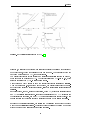

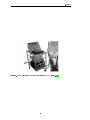
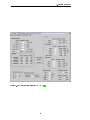


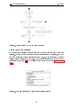
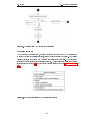

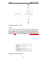
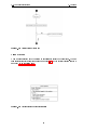
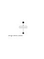

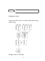

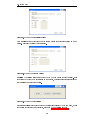


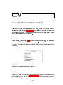
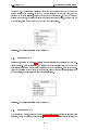

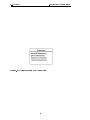
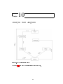


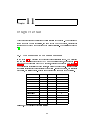

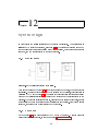


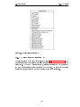
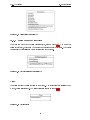
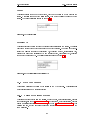
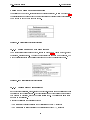


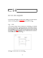

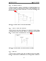
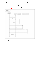


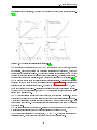


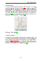


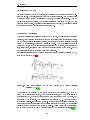
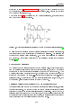
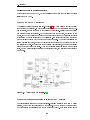


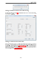
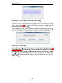
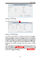


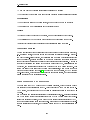

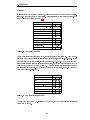


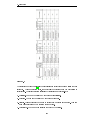


![本棚転倒事故[PDF:847KB]](http://vs1.manualzilla.com/store/data/006643778_2-3d6b3382a58630d271a7cf26f3e1b424-150x150.png)