1
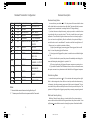
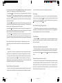
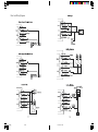
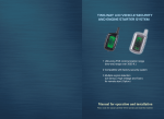
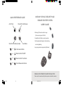
QUICK REFERENCE GUIDE
ONE WAY VEHICLE SECURITY AND
ENGINE STARTER SYSTEM
Arm/Panic
Disarm/Trunk Release
USER’S GUIDE
Ultra-long FM remote control range
(One-way range up to 800m)
Compatible with factory security system
Code hopping technology for anti-scanning
Silent Arm/Auxiliary Output
See Below
and anti-grabbing
Long-range remote engine start (Optional)
+
Continuation Mode
+
Remote Start ON/OFF
+
Remote Start Time Mode
+
Turbo/Reservation Mode
MANUAL FOR OPERATION AND INSTALLATION
Please read this manual carefully before operate and install the machine
ֆཟႇ໓̺̻̾̿̾ͽͺ̻̓͂
2-3
2006.1.21, 11:27
Introduction
Table of Contents
Introduction ............................................................................................................................... 2
Standard Transmitter Configuration ....................................................................................................................... 3
Features Description............................................................................................................................... 4
Standard Arming Mode............................................................................................................................... 4
Silent Arming Mode............................................................................................................................... 4
Multi-level Security Arming ............................................................................................................................... 4
Disarming............................................................................................................................... 5
Security Rearming (Programmable)............................................................................................................................... 5
Panic Mode............................................................................................................................... 6
Door Status Warning (Programmable)............................................................................................................................... 6
Trunk Release............................................................................................................................... 6
Central Lock Automation (Programmable)............................................................................................................................... 6
Passive Arming and Passive Locking
............................................................................................................................... 6
Arming Reminder ............................................................................................................................... 7
Smart LED Indicator ...............................................................................................................................7
Automatic Windows Rolling-up............................................................................................................................... 7
Auxiliary Output (Programmable) ............................................................................................................................... 7
Status Memory...............................................................................................................................7
Automatic Dome Light...............................................................................................................................7
Remote Engine Start (Must need remote start module)
...........................................................................................................8
How to Drive Your Remote Started Vehicle
...............................................................................................................................8
Remote Shut Down...............................................................................................................................9
Continuation Mode (Remote start model only)............................................................................................................................9
Turbo/Short Run (Remote start model only)...............................................................................................................................9
Remote Start Timer Mode (Remote start model only)
...........................................................................................................10
Valet Mode...............................................................................................................................10
Disarming without a Transmitter ...............................................................................................................................11
Code Hopping...............................................................................................................................11
System Installation...............................................................................................................................11
Installation Guide for Receiver...............................................................................................................................12
Harness Description...............................................................................................................................13
Peripheral Plug-in Connectors...............................................................................................................................16
Door Lock Wiring Diagram ...............................................................................................................................17
Features Programming Rountine.............................................................................................................................19
Checklist of Options............................................................................................................................... 20
Transmitters Code Learning Routine.................................................................................................................. 20
Quick Reference Guide for System Wiring.................................................................................................... 21
Limited Warranty ...............................................................................................................................
....................................... 22
Thank you for purchasing This Vehicle Security System.
This vehicle security system features a state-of-the-art technology and
FM design to give you maximum safety and satisfaction in using the system.
1) Please read this manual carefully before using this car alarm so that
you抣l take the full advantage of every marvelous features provided by the
system.
2) The local authorized dealer is responsible for the service and warranty.
3) The system requires no specific maintenance. Your transmitter is powered by a small 12volt 23A lithium battery. When the battery weakens,
operating range will be shortened and the LED on the remote will dim.
4) This device complies with part 15 of FCC rules. Operation is subject
to the following two conditions: (1). This device may not cause harmful
interference, and (2) This device must accept any interference received, including interference that may cause undesired operation. Changes or modifications not expressly approved by the party responsible for compliance
5) Due to the complexity of this system, it must be installed by an authorized dealer only.
6) All the modules and interconnection cables are inaccessible to the end
user except the remote control, the one-way receiver and its signal cables.
Antenna
LED:Status Indicator
Transmitter Series
Three-phase sensitivity
adjustment for shock sensor
Transmitter
1
ֆཟႇ໓̺̻̾̿̾ͽͺ̻̓͂
4-5
Valet Switch
Receiver
2
2006.1.21, 11:27
Standard Transmitter Configuration
Features Description
Standard Arming Mode
BUTTON TIME PRESSED STATUS APPLICABLE
FUNCTION
ARM AND LOCK
will be locked with one siren chirp and one light flash. The starter kill relay becomes
0.5s
DRIVING
LOCK
engaged to avoid unauthorized car starting and the LED begins flashing.
2.0s
NON-DRIVING
PANIC MODE
2.0s
DRIVING
ANTI-ROBBERY
0.5s
ALARMING
STOP ALARMING
0.5s
ARMED/STARTED DISARM AND
0.5s
DRIVING
UNLOCK
2.0s
ARMED AND NORMAL TRUNK RELEASE
0.5s
NORMAL
SILENT ARM
AND LOCK
2.0s
NORMAL
AUXILIARY
CHANNEL 5 OUTPUT
0.5s
ARMED
REMOTE START
TIMER MODE
+
for 0.5s, the system will be armed and the doors
NORMAL
UNLOCK
+
In normal status, press button
0.5s
0.5s
ARMED
If you hear three more chirps after arming, maybe you need to re-check the doors
to see whether they are properly closed. This chirp is called door zone bypass
notification. This notification is given out when some door is not closed properly or
if your car has a dome light delay. After the notification, the system will delay to
monitor the door zone for an additional 20 seconds or until the dome light turns off.
When armed, your vehicle is protected as follows:
1) Light impacts will trigger pre-warning signal. When triggered, the siren will
chirp for 3s and the parking light will flash twice.
2) Heavy impacts will triggered the system to sound the siren and flash the lights
for 15s.
3) If a door/hood/trunk is opened, the system will immediately start chirping the
siren and flashing the parking lights for a period of 30s.
4) Turning on ignition key will triggered the same response as opening a door.
5) If you select to install a Field Disturbance Sensor, such as a microwave sensor,
the system can react to any intrusions into the field with the full triggered sequence.
REMOTE START
ON/OFF
+
0.5s
DRIVING
CONTINUATION MODE
+
0.5s
DRIVING
TURBO MODE
Silent Arming Mode
In normal status, press button
for 0.5s to activate silent arming with one light
flash. In silent arming mode, there will be no siren chirp confirmation when arming
or disarming, also the pre-warning response to light impacts is bypassed. This ensures that no chirps will be emitted by the siren in an area you want chirp-free. The
Notes:
1. Normal status means disarmed and ignition key off.
2. “+”means press the buttons in sequence within 2 seconds.
system is still fully capable of triggering except the pre-warning response bypassed.
Multi-level Security Arming
Multi-level Security Arming allow you to select which of the systems inputs or
sensors will be active and which will be bypassed when the system is armed. Pressing Button
again within five seconds of arming the system will activate the Multi-
3
ֆཟႇ໓̺̻̾̿̾ͽͺ̻̓͂
6-7
4
2006.1.21, 11:27
level Security feature. Each time Button
is pressed again, a different security level
your car from theft even when your car is disarmed by accident.
is selected. The different security levels are selected as follows:
Press Button
once: The siren chirps once. The system is armed. All zones are
active. LED indicator blinks once and then pauses for 2.0 seconds and then repeats.
Press Button
a second time within 5 seconds: The siren chirps once again. The
shock sensor zone is now bypassed. LED indicator blinks twice with a two-second
pause and then repeats.
Press Button
a third time within 5 seconds: The siren chirps one more time. The
Panic Mode
If you are threatened in or near your vehicle , or if you want to identify the parking
location of you car, press button
for 2.0s, and you will enter Panic Mode. The siren
will sound for 16s with light flashing. To stop Panic Mode at any time, press button
for 2.0s again or press button
for 0.5s.
Optional sensor zone (Microwave sensor zone) is now bypassed. LED indicator blinks
three times with a two-second pause and then repeats.
Press Button
a fourth time within 5 seconds: The siren chirps one more time. The
Door Status Warning (Programmable)
The lights will flash to inform you that some door is not closed well. When temper-
Shock sensor zone and Microwave sensor zone are now bypassed. LED indicator
ately parking, such flashing may warn coming cars to take care. It is suggested to
blinks four times with a two-second pause and then repeats.
cancel this feature when your car has a dome light delay.
Press Button
a fifth time within 5 seconds: The siren chirps one more time. The
Shock sensor zone, Microwave sensor zone and Hood Pin Switch input are now
bypassed. LED indicator blinks five times with a two-second pause and then repeats.
Note: Multi-level Security Arming only applies to a single arming cycle. Once
the system is disarmed and then re-armed, all the zones (inputs) will be active
Trunk Release
Press button
for 2.0s to open the trunk. Yo u may select whether disarm and
unlock doors when trunk released by options.(This function is suitable for cars with
electric trunk opener)
again.
Central Lock Automation (Programmable)
This function enables your vehicle to automatically lock the doors upon pressing
Disarming
Tamper Alert: If you hear four additional siren chirps and light flashes, please
check your car to see whether the security system was triggered in your absence.
brake pedal after ignition is on and unlock the doors upon key off. During driving,
you may also press button
to lock or button
to unlock without activating security
mode.
The system will be disarmed and the door will be unlocked with two siren chirps
and two light flashes if press button
for 0.5s. When disarming, if you hear two
additional siren chirps and light flashes, please check your car to see whether it has
been suffered with bumps. This is called trigger reminder.
Passive Arming and Passive Locking
The system also can be programmed to arm itself automatically (call passive arming).
Once passive arming is enable, the system will arm itself in 40 seconds every time
Security Rearming (Programmable)
The system will re-enter into last arming mode automatically if no door is opened
after the system "sees" you turn ignition off and leave your car by opening and closing the doors. If passive locking function is enable, the system will lock doors at the
same time when entering passive arming.
or ignition is still off within 35s after disarmed by remote. This feature is to protect
5
ֆཟႇ໓̺̻̾̿̾ͽͺ̻̓͂
8-9
6
2006.1.21, 11:27
Arming Reminder
The system will turn on the dome light every time you disarm your system. The
The system also can remind you of arming the system if you forgot to do so. The
system will give out three siren chirps with light flashes 20 seconds after you turn off
dome light will go out 30 seconds later or immediately go out after you turn the
ignition on.
the ignition key and close all the doors. After hearing the audible reminder, you
should press button
to arm and lock.
Remote Engine Start (Must need remote start module)
Remote start makes it possible to warm up the engine, as well as adjust the interior
Smart LED Indicator
temperature of the vehicle. If interior heating or cooling is desired, the climate con-
In arming status: LED flashes the same number as the times of pressing button
within
trols must be preset, and the fan blower must be set to the desired level prior to
remote staring the vehicle.
5 seconds.
In turbo state: LED stays solid for 2 seconds, then pause for 2 seconds.
1) In arming mode, press button
for 0.5s and then press button
for 0.5s to
activate the remote engine start function.
In valet mode: LED stays solid.
ACC, Door, Hood/Trunk triggered: LED stays solid for 0.5 seconds, then pause for
2) The siren will chirp once and parking lights flashes once.
3) In gasoline vehicles, the engine will wait 6 seconds after the parking lights
0.5 seconds.
flash. In diesel vehicles, the engine will start when the WA IT-TO-START indicator
on the vehicles dash goes out.
Automatic Windows Rolling-up
This system supplies a windows rolling-up feature. The system will roll up all the
windows at the arming command to ensure safety of your vehicle. ( A windows rolling-up module may be necessary. Please contact your local dealer for details)
4) Once the vehicle has started, it will run for the pre-programmed period of time
(either 15 or 25 minutes) or until a shut-down input is triggered.
Notes:
1.The parking lights will flash every 30 seconds during the engine is running.
Auxiliary Output (Programmable)
Pressing button
for 2.0s will activate auxiliary channel 5 output, which is
programmed to output pulse of 0.5 seconds or 15 seconds or latched,reset with ignition.
This design is to increase your comfort. It can be programmed to operate trunk,
windows, sunroof etc. Please contact your dealer for details.
2. Never start the vehicle if it is not in either PARK or NEUTRAL position and
never forget to activate the parking brake before remote start.
3. For manual transmission vehicles, only when you've been setting the reservation mode, you can start your vehicle.
4. It is unsafe to remote start the vehicle in a garage or other enclosed area.
Breathing the exhaust from the vehicle is hazardous to your health.
Status Memory
This system may remember the status before power off so as to restore the former
working status such as arm mode , disarm mode and Valet mode, even if the power
supply is destroyed.
Automatic Dome Light
How to Drive Your Remote Started Vehicle
When you are ready to drive the vehicle:
1) Press button
0.5s to unlock and disarm and open the door.
2) Insert the ignition key and turn it to the ON (not the START) position in
30 seconds.
3) Press the brake pedal
7
ֆཟႇ໓̺̻̾̿̾ͽͺ̻̓͂
10-11
8
2006.1.21, 11:27
Note: If the brake pedal is pressed before the key is in the ON position, the
6. Exit and secure the vehicle. Press button
for 0.5s.
engine will shut down.
7. The engine will turn off after the programmed run time.
Note: Once you activate the short-run turbo mode,the system will remain this
mode always. If you don't want this mode any more, press button
Remote Shut Down
While the vehicle is running during remote start operation, the system will monitor
the vehicle and will automatically shut down the engine if the system receives any of
the following shut-down inputs:
Remote Start Timer Mode (Remote start model only)
In arming state, press button
1) The brake pedal is pressed.
+ again to
cancel it anytime.
0.5s and then button
0.5s to activate the
2) The hood is opened.
Remote Start Timer Mode. The siren will chirp 4 times and parking lights flash 4
3) The pre-programmed run time (15 or 25 minutes) has elapsed.
times.
4) Press button
and button
In this mode, the system will start the engine every 3 hours, for a maximum of six
again.
cycles. The engine will run for the programmed run time and then shut down to keep
5) The TACH or Oil sensor or High voltage signal disappear.
engine warm in the cold weather. The remote start command
can shut down the
+
engine in timer mode, but the system will remain in the timer mode. To exit timer
Continuation Mode (Remote start model only)
While driving, if you press button
0.5s and then button
0.5s, you are now in
the continuation mode with 5 chirps from the horn and 5 parking lights flashes. The
engine will continue running for 10 minutes even if you take your key from the
ignition. This mode is useful for occasions when you wish to exit and lock the vehicle with button
0.5s for short periods of time, but would like to leave the motor
running and climate controls on, for example, a grocery store. To exit Continuation
Mode, press button
0.5s and then button
0.5s again, or press button
0.5s to
disarm the system, turn the ignition key on and then press the brake pedal.
Turbo/Short Run (Remote start model only)
Turbo mode keeps the engine running after arriving at your destination for a programmed period of 1, 2, or 3 minutes. This allows the systems timer to conveniently
cool down the turbo after you have left the vehicle.
To activate:
a. Timer mode is exited automatically after the sixth run cycle.
b. Press button
c. Press button
0.5s and then button
the brake pedal.
d. If any other shut down zones or alarm has been triggered, the timer mode will
exit.
Valet Mode
Valet mode is used when washing the vehicle or having it serviced. In Valet Mode,
the security system works just as a keyless entry (door lock/unlock, trunk release, car
finding) without any security functions.
To enter or exit Valet mode:
1.Turn the ignition on.
3.Siren chirps three times and lights flash three times.
2. Remove your foot from the brake pedal and leave the engine running.
0.5s and then button
0.5s
4. The siren will chirp three times with three light flashes.
4.LED turns on solidly.
5.Repeat step 1,2 to exit Valet Mode, LED goes out.
5. Turn off the ignition key, the engine will keep running.
9
ֆཟႇ໓̺̻̾̿̾ͽͺ̻̓͂
0.5s again.
0.5s to disarm the system, turn the ignition key on and then press
2.Press and hold the Valet Switch for 3 seconds
1. Park the vehicle and set parking brake.
3. Press button
mode, do one of the following:
12-13
10
2006.1.21, 11:27
Disarming without a Transmitter
If your remote is lost, damaged or any other reason cause you can not control your
security system, you can manually disarm your vehicle security system.
7. Verify with the owner, the mounting locations for all visible components, including the LED and Receiver.
8. Verify with the owner, the optional features of vehicle security system and the
features that must be programmed during installation.
1.Turn the ignition on.
2.Within 5 seconds, press and release the Valet Switch button for over 5 times.
3.Siren chirps twice, lights flash twice, all alarm are released, system returns to
9. Inspect and perform a function test of all vehicle systems before and after the
installation.
10. Always use a Volt/ohm meter for testing vehicle circuits. Never use a test light.
disarm state.
11. Always look before drilling any holes or mounting self-tapping screws. Be sure
fuel lines and exterior wiring looms are clear as they are often close to the chassis
Code Hopping
This system uses code hopping technology to increase the security of the alarm. In
case the remote falls out of sync with the main control unit, you may do the transmitters code learning routine to make the main control unit re-sync the transmitter
automatically.
and difficult to see.
12. Protect all wires running from the engine compartment to the interior of the
vehicle by covering with electrical tape and split loom tubing. Be sure to use a grommet when routing wires through the firewall.
13. Properly fuse any additional accessories such as starter module, window module,
door lock actuators, etc., Making sure to power them separate from the alarm Main
System Installation
1. Due to the complexity of this system, installation must only be performed by an
authorized dealer.
2. Thoroughly read and become familiar with the installation instructions before
beginning the installation.
3. Review system contents:
Unit. This will ensure the functionality of the security system in the event of an
accessory failure.
14. Remove all fuses to avoid running down the battery during installation.
vehicle.
Installation Guide for Receiver
a. Main Control Unit
The mounting place of receiver has a substantial influence upon the communica-
b. Siren
c. One-way receiver with built-in Shock Sensor and Valet Switch
tion range of the system. It is recommended to install the receiver to left-upper side
d. Starter Kill Relay
(left-steering wheel)
e. Remote Starter Module with 5-pin Starter Harness.
note to clean the mounting position with a wet cloth in order to glue the receiver
f. Harness.
firmly.
4. Verify vehicle is equipped with electronic fuel injection, and starts/idles nor -
Hide the wire by carefully
pushing it inside the space
of the front windows blind
mold trim.
mally before installation.
5. Determine if vehicle is equipped with a factory theft deterrent system and obtain
proper bypass module if required.
6. Find a location to mount the hood pin switch that will not interfere with the
opening of the hood, and is not in a position that can accumulate water. The hood pin
is a safety device that must be installed to avoid remote starting during engine servicing.
11
ֆཟႇ໓̺̻̾̿̾ͽͺ̻̓͂
14-15
12
2006.1.21, 11:28
Harness Description
5 Heavy Gauge Starter Harness in the Starter Module (Ignition Switch Interface)
Purple Wire: Starter Output (+). Connect to the vehicle's starter wire.
ORANGE WIRE: Accessory Output (+). Connect to the accessory wire coming
from the ignition switch that supplies power to the heater/air-conditioner. Some cars
may have multiple accessory wires.
PINK WIRE A: Ignition Output (+). Connect to the main ignition wire that provides +12V when the ignition is on and while cranking the starter.
PINK WIRE B: Second Ignition Output (+). Connect to the second ignition wire
of the vehicle.
RED WIRE: Main Power Input (+). Connect to the battery or constant power
wire at the ignition switch with a minimum 30 Amp supply. Remove the fuse until
the installation is completed and all wiring is checked.
7-pin Connector Secondary Harness for Remote Start(H4)
Pin1-3: Factory wiring to the remote start module.
Pin4: BLUE/WHITE WIRE: (-)200ma bypass output when remote start. Connect this wire to the interface of Remote Start Bypass Module.
Pin 5: GREY/ BLACK WIRE: Diesel wait-to-start bulb input. (-) Connect this
wire to the wire in the vehicle that sends the signal to turn on the WAIT-TO-START
bulb in the dashboard. In most diesels, the wire is negative (ground turns on the bulb)
and the GRAY/BLACK wire can be directly connected to the wire in the vehicle. If
the vehicle uses a positive wire (12V to turn on the bulb), you must set the proper
signal polarity in the options list(Features #12).
Pin 6: BLACK/WHITE WIRE: (-)Neutral Safety Switch Input. Connect this
wire to the PARK/NEUTRAL switch in the vehicle. This wire will test with ground
with the gear selector either in PARK or NEUTRAL. This will prevent the vehicle
from accidentally being started while in a drive gear. This input MUST rest at ground
in order for the remote start system to operate. Connected properly the vehicle will
only start while in PARK or NEUTRAL. You may also connect this wire to the Parking Brake Switch.
Pin 7: VIOLET/WHITE WIRE: Oil Sensor signnal (Default), High-Voltage
Sensing/Tachometer input (OPtional). This input provides the module with information about the engines resolu tion per minute (RPMs). Connect to the vehicle's tach
wire. Common locations for a tachometer wire are the ignition coil, instrument cluster,
fuel injectors, or engine computers. The correct wire shows between 1V to 6V (AC)
and fluctuates with the idle of the engine when testing with a multi-meter capable of
testing AC voltage.
Note: This wire has the same function with the High-Voltage sensing input, so it
is a alternative solution when voltage sensing input does not supply satisfactory
operation. If connect to the High-Voltage sensing input, you must coil this wire
five loops onto the High-Voltage from the engine distributor.
10-Pin Connector Primary Harness (H1)
Pin 1: BROWN WIRE: Siren Output (+). The brown wire must connect to the
red wire of the siren. The black wire must be grounded.
Pin 2: WHITE WIRE: Parking Light Output (+/-) Relay. Connect this wire to the
circuit that shows +12V or ground only when the parking lights are on and set the
internal parking light relay jumper to the proper polarity. For parking light circuits
exceeding 10 Amps, a relay is required. For vehicles with independent left and right
parking light circuits, diodes must be installed to keep the circuits separate.
Note: Do not connect the white wire to the vehicles headlight circuit.
Pin3: Violet: Unlock #87a Normally Closed
Pin4: Blue/Black: Unlock #30 Common (Output)
Pin5: Brown/Black: Unlock #87 Normally Open (Input)
Pin6: Violet/Black: Lock #87a Normally Closed
Pin7: Green/Black: Lock #30 Common (Output)
Pin8: White/Black: Lock #87 Normally Open (Input)
Pin9: Red: Constant +12V Input. Connect this wire to the battery or Constant
Power wire at the Ignition Switch with a 15Amp Supply.
Pin10: Black: System Ground. Connect this wire firmly to the Chassis Ground.
6-pin Secondary Harness for Outputs(H2)
Pin 1: ORANGE WIRE: Armed Output (-) 500mA. The orange wire supplies a
ground output while armed to activate a relay for starter defeat and anti-grind
protection.
13
ֆཟႇ໓̺̻̾̿̾ͽͺ̻̓͂
16-17
14
2006.1.21, 11:28
Pin 2: BLUE WIRE: Second unlock (passenger unlock)output (-) 200mA This
Pin 2: GREEN/WHITE WIRE: Factory Rearm Output (-) 500mA. This wire
system is equipped with a dedicated passenger unlock output allowing two stage
supplies a ground output on remote start shutdown to rearm a factory security system.
door lock operation. When connected this wire, disarming the system will unlock
Connect to the wire that requires a ground pulse to rearm the factory security system.
Pin 3: BLACK WIRE: Optional Sensor Input (-).Connect to an optional instant
only the driver s door. Pressing the disarm button again will unlock all doors..
sensor such as trunk pin switch.
Pin 3: WHITE/BLACK WIRE: Auxiliary Channel 5 Output (-) 200mA. This
wire provides a (-) 200mA output whenever the transmitter button
is pressed for
Pin 4: GREY WIRE: Hood Pin Input (-). Connect this wire to the hood pin switch.
The switch must supply a ground output(-)when switch is opened. This input will
2S. This output can be programmed to provide the following types of outputs:
a. 0.8-second timed: Output that will send a ground pulse of 0.8 second.
disable or shut down the remote start when the hood is opened. It will also trigger the
b. 15-second timed: Output that will send a ground continuous pulse for 15 seconds.
security system if the hood is opened while the system is armed.
c. Latched,reset with ignition: Output that will send a signal when the Channel 5
button (button
) is pressed and will continue until the same button (button
) is
pressed again. It additionally stops output whenever the ignition is turned on.
Pin 4: PURPLE/BLACK WIRE: Auxiliary 4 Output (-)500mA for windows
rolling-up option. Connect to a power window module.
Pin 5: BLACK/WHITE WIRE: Dome Light Output (-) 500mA. Connect to the
Pin 5: BROWN WIRE: Brake Input (+). Connect to the wire that shows +12V
when pressing the brake. The brown wire is a safety shutdown wire that must be
connected.
Pin 6: YELLOW WIRE: (+) Ignition Input of the Key Cylinder to Alarm. Connect to the ignition wire that provides +12V when the ignition is on and while cranking the starter.
wire that activate the vehicle's dome light, usually the door pin switch wire. Note: the
Pin 7: GREEN WIRE: Negative Door Input (-). Most vehicles use negative door
dome light output can usually connect to the same wire used for the door trigger
trigger circuit. Connect the green wire to the wire that shows ground when any door
input (see purple and green door input wire).
is opened. In vehicles with factory delays on the dome-light circuit, there is usually a
wire that is unaffected by the delay circuit.
Note: This output is only intended to drive a relay. It can not be connected
Pin 8: PURPLE WIRE: Positive Door Input (+). Connect to the door switch
directly to the dome light circuit, as the output cannot support the current draw
circuit wire that shows +12V when any door is opened. This type of door circuit is
of one or more light bulbs.
usually found on Ford Vehicle.
Never use this wire to drive anything but a relay or a low-current input. The
transistorized output can only supply 200mA of current. Connecting directly to
a solenoid, motor, or other high-current device will cause it to fail.
Pin 6: RED/WHITE WIRE: Vehicle Trunk Release Wire (-)500mA. Connect
this wire to the electronic trunk opener. (Relay may required).
8-pin 2510 Harness for Inputs and Outputs(H3)
Pin 1: GREEN/BLACK WIRE: Factory Disarm Output (-) 500mA. This wire
Peripheral Plug-in Connectors
7-PIN White Connector: One-way Receiver Port
3-PIN Black Connector: Optional Sensor Input port, for example, the Microwave Sensor.
2-PIN White Connector: LED Port. Mount LED in an area where it may be
easily seen from either side of the vehicle.
provides a ground output on disarming and before remote starting to disarm a factory
security system. Connect to the wire that requires a ground pulse to disarm the factory security system.
15
ֆཟႇ໓̺̻̾̿̾ͽͺ̻̓͂
18-19
16
2006.1.21, 11:28
Door Lock Wiring Diagram
17
ֆཟႇ໓̺̻̾̿̾ͽͺ̻̓͂
20-21
18
2006.1.21, 11:28
Checklist of Options
Features #
Option1(Default)
1.Power motor/Vacuum
Power motor
Option2
Vacuum
door locking system
(0.8s pulse)
(3.5s pulse)
Single
Double
3.Automatic rearming
ON
OFF
4.Auto door lock/unlock
ON
OFF
ON
OFF
6.Passive Arming
OFF
ON
7.Passive locking in passive
OFF
ON
2.Single/double pulse unlock
Option3
when ignition is on
5.Parking lights flash when
door opened in disarm mode
arming mode
8.Auxiliary Channel 5 Output
Features Programming Rountine
Step 1:In the disarming state, turn the ignition key to the "OFF" position, then
0.8 second pulse 15 seconds pulse Latched output
9.Disarm when trunk release
ON
OFF
10.Parking Lights Flashing/Constant
11.Gasoline/Diesel Engine Start
Flashing
Constant
Gasoline
Diesel
12.Glow plug polarity of Diesel
press and release valet switch for 5 times rapidly within 10 seconds. The siren will
13.Engine Run time
Negative
15 min
Positive
25 min
chirp four times and parking lights will flash four times , which indicate features
14.Short Run/Turbo
1 min
2 min
3 min
programming mode is activated. In this mode, the LED goes out.
Step 2:Press and release the valet switch the same number of times as the desired
features number of which is going to be programmed. Status LED flashes the same
number of times following by a 1.5 second pause.
Step 3:Press button
to select the first option, siren will chirp once and lights
will flash once. Press button
to select the second option, siren will chirp twice and
lights will flash twice. Press button
to select the third option, siren will chirp
three times and lights will flash three times.
Note: Repeat step 2 and step 3 for each feature to be changed. If no programming active within a 10 second period, the Features Programming Mode will
expire.
Transmitters Code Learning Routine
You may program a new transmitter if the original one was lost or damaged, but
remember to delete the data of the lost transmitter from the Main Unit for safety
purpose.
Step 1:In disarming state, turn the ignition key to “ON” position, and then press
and release the Valet Switch for over 5 times, the LED will flash rapidly to indicate
that transmitter learning mode is activated.
Step 2: Within 6 seconds, Press the button
0.5s and then press the button 0.5s
of the pre-programmed transmitter. Siren will chirp 5 times and parking lights will
flash 5 times to confirm that the new transmitter code learning has been successful.
Step 3: Repeat Step 1 and Step 2 again to do the second new transmitter code
learning.
Note: If no button is pressed within 10 seconds, the system will exit code learning mode without changing the original transmitter.
19
ֆཟႇ໓̺̻̾̿̾ͽͺ̻̓͂
22-23
20
2006.1.21, 11:28
Quick Reference Guide for System Wiring
Limited Warranty
This Alarm & Starter product is warranted against manufacturing defects in material and workmanship for 180 days from the date of purchase from the authorized
Dealer.
During the period, the Dealer will repair the products without charging the parts
and labor cost.
The warranty does not cover damage or failure caused by or attributed to Act of
God, abuse, misuse, improper or abnormal usage, improper maintenance, lightning,
or other incidence of excess voltage, or any repairs other than those provided by the
When warranted time is expired, Dealer will repair the products only charging the
parts cost.
Purchase Information
Name of Dealer
Address
Zip Code
Phone
Fax
Date of Purchase
Signature of Installation Engineer
Product Information
Model
Type of Vehicle
Serial number of Remote Control#1
Serial number of Remote Control#2
21
ֆཟႇ໓̺̻̾̿̾ͽͺ̻̓͂
24-25
22
2006.1.21, 11:28