1
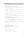
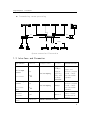
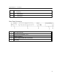
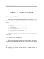
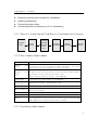
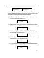
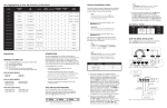
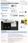
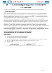
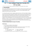
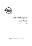
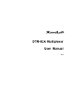
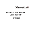
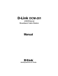
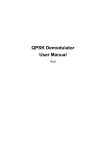
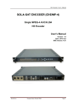
Single Multiplexer
User Manual
Ver2.0
Single Multiplexer User Manual
Chapter 1 Product Outline
1.1 Outline
single multiplexer, with our company own intellectual property rights,
is a embeded digital video communication product, a digital broadcasting TV
system TS stream re-multiplexer. Based on PID package interchange technology, it
can combine several single-programs or multiple-programs, which are compressed, coded,
and multiplexed according to customer request by head-end, into single transport stream.
And it can insert EPG(Electronic Program Guide)
、CA(Conditional Access)and data
broadcast signal into the output TS stream. Choose one TS stream to multiplexer, and
output is MPTS, and it can creat SI/PSI information automatically, also with service and
PID filter, and re-multiplexer function. It can receive 8 routes TS stream, and
can insert the SI table from the service information server in real time,
thereby realize more value-added services, like EPG, data broadcast, etc. It
adopted the solution of minimum volume and lowest price, and it meets MPEG-2
standard, can be used in TV station, digital video inspection, and so on.
1.2 Features
•
Support up to 8 routes ASI inputs, can be cascading
•
Output code rate continuously adjustable, max output real data rate
to 100Mbps
•
Support up to 155Mbps real data rate for each route input, and support
package burst mode
•
Input TS stream package length (188/204) adapting
•
3 routes ASI output interfaces
1
Single Multiplexer User Manual
•
With input MPTS analysis function, display the input programs and
output valid stream
•
High definition PCR adjustment, average PCR tremble keep in 20-60ns
•
PID filter/PID redefine function, the customer can add/delete programs
and PID, also modify PID
•
LCD panel, can inspect the system status in real time, and set the
parameters of multiplexer remotely
•
With ethernet interface, can control the multiplexer through PC
remotely
•
With parameters save function, will call out the parameters
automatically when turn on the multiplexer
•
Failure insulation function, one abnormal input TS stream will not
impact other TS streams
•
Very low time delay, the time between input and output will keep in 1 ms
•
With bandwidth protection function
•
Code rate adapting. When VBR change, it can keep toal output code rate constant
•
Support CA system, EPG, EMM and ECM
•
With PSI creating function. The customer can edit SDT and NIT, and
extend their SI service via ethernet
Application
l
Program gathering/distribution
l
SDH network transmission, satellite DVB-T, MMDS
l
CATV headends
l
VOD
l
Digital transfering
l
Video distribution in TV network
l
Transmitting stream and re-multiplexer
2
Single Multiplexer User Manual
l
Transmitting stream processing
Satellite Receiver
Multiplexer
Satellite Receiver
MPEG-2 Encoder
MPEG-2 Encoder
Video Server
ASI
ASI
Ethernet
RS232/422
Multiplexer
Hub
Console
ASI
DS3/E3
ASI
EPG Server
控制台
QAM Modulator
MPEG-2Encoder
PDH/SDH
System connection illustration
1.3 Interface and Parameter
Input Interface
DVB ASI Input
Interface
(8 routes)
DVB ASI Output
Interface
Connector
Package Format
Bit rate
Grammar/Character
188/204 adapting
Up to
155Mbps,
support
equality
mode and
package
burst mode
Single and
multiple program
stream, comply
with ISO-13818
standard
BNC,
75
BNC,
188/204 adapting
(3 routes,
same)
120Mbps
75
Ethernet
interface
RJ45
Basic
Dimension
10Base-T
Single and
multiple program
stream, comply
with ISO-13818
standard
Can realize
remote control,
and EPG,PSI,SI
service
44mm×482mm×330mm
3
Single Multiplexer User Manual
;-20~80℃(storage)
specification Environment 0~45℃(working)
Power
110~220VAC±10%,50/60Hz,25W
Supply
1.4 Principle Chart
Ethernet
TS Input
module
PS232/4
85
module
8 input
PID filtrate, mapped
CH analyse, select
Controlling module
Keyboard
LCD
PID filtrate, mapped
CH analyse, select
TS adjusting,
controlling
Output module
multiplexing
TS adjusting,
controlling
Output module
multiplexing
1.5 Appearance and Description
Front Panel Illustration:
Multiplexer
1
2
3
4
1
5
6
578
6
7
8
Enter
Digital
Video
Broadcasting
Menu Lock
Power
3
2
1
LCD Display Interface
2
Power Indicator
3
Input TS stream indicator
4
Up /Down/Left/Right Arrow
4
5
6
7
4
Single Multiplexer User Manual
5
Enter key
6
Menu button
7
Lock button
Rear Panel Illustration:
1
ASI output interface
2
1~8 ASI input interfaces 1 to 8
3
Ethernet interface
4
Power supply and filter all in one socket
5
Grounding
5
Single Multiplexer User Manual
Chapter 2 Installation Guide
2.1 Acquisition Check
When users open the package of the device, it is necessary to check
items according to packing list. Normally it should include the following
items:
l
Multiplexer…………………………………1
l
User’s Manual ………………………… 1
l
AC Input Power Cord………………………1
l
Output interface connecting cable ………2
If any item is missing or mismatch with the list above, please contact
local dealer.
2.2 Installation Preparation
When users install device, please follow the below steps. The details of
installation will be described at the rest part of this chapter. Users can also
refer rear panel chart during the installation.
The main content of this chapter including:
n
Checking
the
possible
device
missing
or
damage
during
the
transportation
6
Single Multiplexer User Manual
n
Preparing relevant environment for installation
n
Installing Multiplexer
n
Connecting signal wires
n
Connecting communication port (if it is necessary)
2.2.1 Device’s Installation Flow Chart Illustrated as following:
Acquisition
Check
Fixing
Device
Connecting
Grouding
Wire and
Power
Cord
Connecting
Signal Wire
Setting
Parameter
Running
Device
2.2.2 Environment Requirement
Item
Machine
space
hall
Machine
floor
hall
Environment
temperature
Relative
temperature
Pressure
Door & window
Wall
Fire protection
Power
Requirement
When user install machine frame array in one machine hall, the
distance between 2 row of machine frames should be 1.2~1.5m and
the distance to wall should be no less than 0.8m。
Electric Isolation, Dust Free
Volume resistivity of ground anti-static material:1(107~1(1010(,
Grounding current limiting resistance: 1M(。
Floor bearing should be greater than 450Kg/m2。
5~40(C sustainable ,0~45(C short time,
installing air-conditioning is recommended
20%~80% sustainable 10%~90% short time
86~105KPa。
Installing rubber strip for sealing door-gaps and dual level
glasses for window
It can be covered with wallpaper, or brightness less paint.
Fire alarm system and extinguisher
Requiring device power, air-conditioning power and lighting power
are independent to each other. Device power requires AC power 220V
50Hz,50W Please carefully check before running.
2.2.3 Grounding Requirement
7
Single Multiplexer User Manual
n
All function modules’ good grounding designs are the base of reliability and
stability of device. Also, they are the most important guarantee of lightning
arresting and interference rejection. Therefore, system must follow this rule.
n
Coaxial cable’s outer conductor and isolation layer should keep sound electric
conducting with the metal housing of device.
n
Grounding conductor must adopt copper conductor in order to reduce high
frequency impedance, and the grounding wire must be as thick and short as
possible.
n
The 2 terminals of grounding wire must make sure for well electric conducting,
and process for antirust.
n
It is prohibited that users use other devices as part of grounding wire’s electric
circuit
n
The section of the conjunction between grounding wire and device’s frame
should be equal or greater than 25mm2
2.2.4 Frame Grounding
All the machine frames should connect to protective copper strip. The
grounding wire should be as short as possible and avoid circling. The section of
the conjunction between grounding wire and grounding strip should be equal or
greater than 25mm2.
2.2.5 Device Grounding
Connecting the device’s grounding rod to frame’s grounding strip with
copper wire.
2.3 Wire’s Connection
8
Single Multiplexer User Manual
l
The power supply outlet is located at the left of rear panel, and the power
switch is just above it. The protective grounding wire connective screw is located at
the down-left side of power supply outlet
l
Connecting Power Cord: User can insert one end into power supply outlet,
while insert the other end to AC power.
l
Connecting Grounding Wire: When the device solely connects to protective ground, it
should adopt independent way, say, share the same ground with other devices. When the device
adopts united way, the grounding resistance should be smaller than 1Ω
Notice: Before connecting power cord to Encoder, user should set the power switch to “OFF”.
2.4 Signal Wire Connection
The signal connections include the connection of input signal wire
and the connection of output signal wire. The signal connection wire are
both ASI.
2.4.1 ASI Input Connection
User can find ASI IN1-IN8 input port on the Equipment, according to connector mark described
in the rear panel illustration, and then, connecting the Q9 coaxial cable, one end to the ASI IN1-8 and
the other end to the Encoder’s or other equipment ASI output port.
2.4.2 ASI Output Port Connection
User can find ASI output port on the Equipment, according to connector mark described in the
9
Single Multiplexer User Manual
rear panel illustration, and then, connecting the ASI cable (in the accessories), one end to the
multiplexer’s ASI output port and the other end to the scrambler’s or Modulator’s input port.
multiplexer’s ASI output port and its connected ASI cable connector illustrated as follow:
Chapter 3 Operation
This multiplexer’s front panel is user operation interface. Before
operating, we should collocate input and output parameter. Input setting
includes the select of multiplexed channels, output parameter includes
setting of TS output. Equipment supply perfect menu for user select, detail
operations go as follows:
1. Front Panel Keyboard Function Description
LOCK button: menu keyboard
ENTER: Activating and edit the parameters which needs modify, or
confirming the change after modification and turn over;
MENU: Cancel, back to the previous menu
LEFT、RIGHT:In modifying mode, change parameters or move cursor
10
Single Multiplexer User Manual
UP、DOWN: In modifying mode, change parameters, in menu mode, page
up and page down
2. Main page
2.1 Start-up interface:
复用器
000.000Mbps
Ver2.01
l
Ver2.01 indicate software version。
l
000.000Mbps indicate output TS stream, if total output TS stream is
less than valid TS stream, here will display “overflow”
3. Menu operation
press LOCK to enter main menu, In main menu, press UP and DOWN
to page up and page down, press enter key to confirm.
1: *语言/language
2:Output Parameter
5:*Apply Output
6:NET Parameter
3: Channel Search
4: Program Select
7:*Resume Default
8:Reset System
3.1 【语言/language】Press LEFT and RIGHT to choose“English/*中文” ,
press ENTER to confirm, press MENU to exit.
1.1: *语言/language
*English 中文
3.2【Output Parameter】press ENTER to entry,press UP and DOWN to page
up and page down, press enter key to confirm. press MENU to exit.
2.1:*Total-Rate
2.2:Special PID Ma
2.5:PAT Interval
2.6:PMT Interval
11
Single Multiplexer User Manual
2.3:*CA Output Enab
2.4:CAT Interval
2.7:*SDT Interval
2.8:NIT Interval
Note: “Special PID mapping/CA output Function”, when configured with
network management, should press NO when you choose the output on the
panel, and can only be reconfigured by network management.
3.2.1 Total-Rate,Press UP and DOWN to modify the parameters, press
ENTER to confirm, press MENU to exit.
2.1.1: Total-Rate
38Mbps
3.2.2 Special PID Ma, Press LEFT and RIGHT to choose“*NO/YES”, press
ENTER to confirm, press MENU to exit.
2.2.1: Special PID Ma
*NO
YES
3.2.3 CA Output Enab , Press LEFT and RIGHT to choose“*NO/YES”, press
ENTER to confirm, press MENU to exit.
2.3.1: CA Output Enab
*NO YES
3.2. 4
CAT Interval
Press UP and DOWN to modify the parameters,
press ENTER to confirm, press MENU to exit.
2.4.1: CAT Interval
150ms
3.2.5 PAT Interval Press UP and DOWN to modify the parameters, press
ENTER to confirm, press MENU to exit.
2.5.1: PAT Interval
40ms
12
Single Multiplexer User Manual
3.2.6
PMT Interval
Press UP and DOWN to modify the parameters,
press ENTER to confirm, press MENU to exit.
2.6.1: PMT Interval
94ms
3.2.7
SDT Interval
Press UP and DOWN to modify the parameters,
press ENTER to confirm, press MENU to exit.
2.7.1: SDT Interval
300ms
3.2.8 NIT Interval Press UP and DOWN to modify the parameters, press
ENTER to confirm, press MENU to exit.
2.8.1: NIT Interval
500ms
3.3【Channel Search】Press LEFT and RIGHT to choose“NO All CH->1
” , press ENTER to confirm, press MENU to exit.
3.1: Channel Search
*NO
All CH->1
6:
3.4【Program Select】choose channel first, press ENTER to choose the
program,Press LEFT and RIGHT to choose“*NO/YES”, press ENTER to
confirm, press MENU to exit.
4.1: *CH1
4.2:CH2
4.1.1: CCTV-1
NO
*YES
3.5【Apply Output】After finish the above operations, you must do this
operation. Press LEFT and RIGHT to choose“*NO/YES”, press ENTER
to confirm, press MENU to exit.
5.1:
Apply Output
*NO
YES
13
Single Multiplexer User Manual
3.6【NET Parameter】Press ENTER to entry. Must reboot the system after
configuration. The client can use hard reboot or soft reboot.
6.1: *IP Address
6.2:Port
6.3:*SubNet Address
6.4:MAC
【IP Address】/【Port】/【SubNet Address】/【MAC】
。Press UP and
DOWN to page up and page down, press ENTER to modify,
press ESC to exit.
6.3.1: SubNet Address
255.255.255.000
6.4.1: MAC
00-03-64-00-01-21
3.7【Resume Default】Press ENTER to entry,Press LEFT and RIGHT to
choose“*NO/YES”, press ENTER to confirm, press MENU to exit.
7.1: Resume Default
NO *Yes
3.8 【Reset System】Press ENTER to entry,Press LEFT and RIGHT to
choose“*NO/YES”, press ENTER to confirm, press MENU to exit.
8.1: Reset System
NO *YES
When all the configuration finished, the system will operate properly.
14