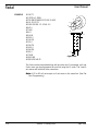
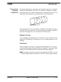
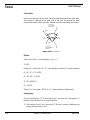
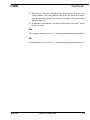
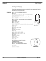
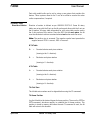
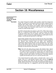
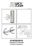
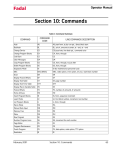
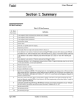
1
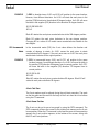
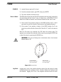
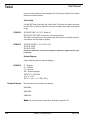
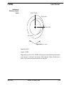
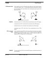
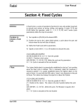
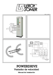
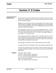
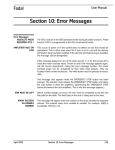
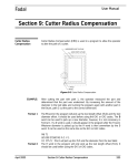
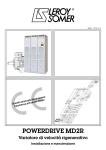
Fadal
User Manual
Section 12: Rotary Axes
A Axis
Direction of Motion
Direction of motion is defined as per ANSI/EIA RS-274-D. Since the VMC
rotates the work piece, the rotary head must rotate clockwise to achieve a
counterclockwise tool motion and visa versa.
The positive sign is assumed. The Negative symbol must precede the angular
amount. A-90. is correct, -A90. is incorrect.
A+ = Counterclockwise work piece rotation (viewing in the X+ direction).
A- = Clockwise work piece rotation (viewing in the X+ direction).
END POINT
G91 (A+90ß)
START POINT
G91 (A-270ß)
Figure 12-1 Direction of Motion
G90 Absolute Mode
April 2003
In the absolute mode (G90) the A word value defines the final position between
0 and 360. The + or - signs define the direction of rotation. The + sign causes
counterclockwise work piece rotation, the - sign causes clockwise rotation to
the indicated degree. There are two possible ways to get to a position on the
rotary table in absolute: by rotating either from the positive or negative
direction.
Section 12: Rotary Axes
265
Fadal
User Manual
EXAMPLE:
1) G90: In absolute terms A+90. and A-90. will position to the same location;
however, from different directions. An A+90. will rotate the work piece in the
positive (CCW) direction to the absolute 90 degree location. An A-90. will move
the table in the negative (CW) direction to the absolute 90 degree location.
N1 G0 G90 A90.000
N2 A-0
Block N1 rotates the work piece counterclockwise to the 90th degree position.
Block N2 rotates the work piece clockwise to the zero degree position.
Changing N2 to a value of A+0 would cause counterclockwise rotation to the
zero degree.
G91 Incremental
Mode
In the incremental mode (G91) the A axis value defines the direction and
number of degrees to rotate. An A+90. causes the work piece to rotate
counterclockwise 90 degrees. If the next move were an A-90. the work piece
would rotate clockwise to the original position.
EXAMPLE:
1) G91: In incremental terms A+90. and A-270. will position to the same
location; however, from different directions. An A+90. will move the table in
the positive (CCW) direction 90 degrees from its current position. An A-270.
will move the table in the negative (CW) direction 270 degrees from its
current position.
N1 G0 G91 A+90.
N2 A-90.
Block N1 rotates the work piece counterclockwise 90 degrees. Block N2 will
rotate the work piece clockwise 90 degrees.
A Axis Cold Start
The A axis markers must be aligned during the cold start procedure. The mark
on the face plate and the mark on the body of the A axis must be in line before
using the CS command.
A Axis Home Position
The A axis can be set to zero at any angle by using the SETA command. The
SETA command will store the current A axis position into memory as the A axis
home position. When the CS command is used and the move to home question
appears the A axis position appears, at the bottom of the screen, along with
the XYZ and B axis positions.
266
Section 12: Rotary Axes
April 2003
Fadal
User Manual
EXAMPLE:
1) Jog the fixture or part until it is level.
2) From the command mode, type SETA, then press ENTER.
3) The A axis should now be set to zero.
Move to Home
The G28 code in format one and the HO command return the rotary head to the
set point along with the X and Y axes. In format two, a G90 G28 X0 Y0 A0
needs to be coded so that the A axis will move home with the X and Y axes.
1) If the current Z axis position is above (+) the HOME position, the X, Y and A
axis moves to zero first, then the Z axis moves in the negative direction.
2) If the current Z axis position is below (-) the HOME position, the Z axis
moves in a positive direction (to zero) first, then the X, Y, and A axis move to
zero.
After the HO moves are computed, the CNC enters the waiting state. The
operator can command the execution of the moves by pressing the START key
or abort the moves by pressing the MANUAL key.
!
WARNING: This move will always be in the direction that is the shortest
distance back to A0.
0˚
180˚
180º OR GREATER
FACEPLATE ROTATES
'CCW' TO GET HOME
LESS THAN 180º
FACEPLATE ROTATES
'CW' TO GET HOME
Figure 12-2 Move to Home
Jog Mode
April 2003
Jogging the A axis in the positive direction causes the work piece to rotate
counterclockwise when viewing in the X+ direction. Relative tool motion would
be clockwise. Jogging the A axis in the negative direction causes the work
Section 12: Rotary Axes
267
Fadal
User Manual
piece to rotate clockwise when viewing in the X+ direction. Relative tool motion
would be counterclockwise.
A Axis Brake
Use the M60 code to activate the A axis brake. The brake will remain activated
until the M61 is coded or another A axis move is made, either from the program
or jog.
EXAMPLE:
N1 G90 G0 M61 Y-2.3 X1.3 Brake off
N2 Z1.6754 A90. M60 Z and A axis move then brake on
An M-60 is used with an A move when using fixed cycles so that the cycle will
not execute until the brake is applied.
EXAMPLE:
N10 G82 G99 R0+.1 Z-.25 F45. P130
N11 A30. M-60
N12 A60. M-60
On line N11 and N12 the A axis moves into position, the brake is applied, then the cycle
is executed.
Decimal Degrees
A axis values are given in decimal degrees.
EXAMPLE:
Numerical Format
d° = Degrees
m’ = Minutes
s" = Seconds
DD = Decimal degrees
40°30’13" = 40.50361
d° m’ s" = DD
DD= d° + (( m’ + ( s" / 60)) / 60 ))
No more than seven numbers are allowed.
A##.#####
A###.####
A####.###
Note: The decimal point is required for all angles except for A0.
268
Section 12: Rotary Axes
April 2003
Fadal
User Manual
Maximum &
Minimum Angular
Limits
START POINT
G90 (A+90ß)
END POINT
G90 (A-90ß)
Y+
X+
Figure 12-3 Max. & Min.
Smallest: A.002
Largest: A1080.
Programming a G91 G1 X2. A1080. will cause an interpolated move where the
X axis moves 2. and the A axis moves 1080. degrees. When a fixed cycle is
used, A axis motion will cause execution of the cycle.
April 2003
Section 12: Rotary Axes
269
Fadal
User Manual
EXAMPLE:
N1 M6 T1
N2 (TOOL #1, DRILL
N3 G0 G90 S10000 M3 E1 X0 Y0 A30.
N4 H1 D1 M7 Z.1
N5 G81 G99 R0.1 Z-.5 F40. X.5
N6 X2.5
N7 A90.
N8 X.5
N9 A150.
N10 X2.5
N11 A210.
N12 X.5
N13 A270.
N14 X2.5
N15 A330.
N16 X.5
N17 G80
N18 M5 M9
N19 G0 G90 H0 Z0
A0ß
Y0
Z0
60ß
X0
0ß
30ß
60ß TYP
.50
2.0
Figure 12-4
The A axis can be interpolated along with any other axis. For example, an X and
A axis move can be programmed on one line using the G1 code. The X and A
axis moves will both end at the same time.
Note: A G2 or G3 will not accept an A axis move in the same line. (See Flat
Cam Programming).
270
Section 12: Rotary Axes
April 2003
Fadal
User Manual
EXAMPLE:
N18 M6 T3
N19 (TOOL #3, 3/8 (.375) 2FL EM
N20 G0 G90 S8000 M3 E1 X3.5 Y0 A0
N21 H3 D3 M7 Z.1
N22 G1 Z-.27 F10.
N23 G91 F50.
N24 X1.
N25 X-1.A-30.
N26 X-1.A30.
N27 A90.
N28 X2.
N29 A-90.
N30 X1.
N31 Z.1 G0
N32 M5 M9
1.00
1.00
30ß
90ß
2.00
Figure 12-5
Degree Feedrate
Calculation
The actual move distance must be calculated before the feed rate can be
determined. This distance may be estimated; however, for best results use the
equation below.
The following example is programmed for a part with a diameter of 4.0. The
desired cut is 90 degrees interpolated with an X axis move of 3.0 (see line N6
of the example program below). The feed rate used for calculation was 25 ipm.
Actual move distance = Sqrt (((Dia. of surface to be cut * 3.14159) / (360 /
Degrees of rotation))2 + X2)
EXAMPLE:
Actual move distance
= Sqrt (((4 * 3.14159) / (360 / 90))2 + 3.02)
= Sqrt ((12.56636) / 4)2 + 9)
= Sqrt ((3.14159)2 + 9)
= Sqrt (9.8696 + 9)
= Sqrt (18.8696)
= 4.3439
(G94) Feed Rate = Degrees of Rotation / (Actual Move Distance / Desired Feed
Rate)
April 2003
Section 12: Rotary Axes
271
Fadal
User Manual
EXAMPLE:
Feed rate
EXAMPLE:
G94
= 90 / (4.3439 / 25)
= 90 / .173756
= 517.97
N1 M6 T1
N2 (TOOL #1, 1/2 END MILL
N3 G0 G90 S5000 M3 E1 X0 Y0 A0
N4 H1 M8 Z.1
N5 G1 Z0 F25.
N6 X3. A90. F517.97
N7 X1. 25 Inches per Minute move
N8 X3. A90. 517.97 Degrees per Minute
N9 G90 G0 H0 Z0
Note: The machine control default is G94, therefore it is not required to code
the G94 into the program if degrees per minute is used.
Note: An F word, on a line with an A axis move only, represents degrees per
minute.
Feed Rate
Specification in
Degrees per Minute
G93 - 1/T (Inverse
Time)
272
Table 1: Feed Rate Specification
Axis Ratio
Maximum Rapid Traverse
Maximum Programmable
Feed Rate
360:1
2000
1250
180:1
4000
2500
120:1
6000
3750
90:1
8000
5000
72:1
10000
6250
The G94 code is used more commonly than the G93. G93 was used by controls
that did not interpolate XA or YA moves. The advantage of using G94 (the
default code) is to allow the programmer to switch between ipm and dpm with
no code cancellation. Except for code cancellation, G94 and G93 effectively cut
the A axis interpolated move in the same way.
Section 12: Rotary Axes
April 2003
Fadal
User Manual
The following example is programmed for a part with a diameter of 4.0. The
desired cut is 90 degrees interpolated with an X axis move of 3.0 (see line N6
of the example program below). The feed rate used for calculation was 25 ipm.
Actual move distance = Sqrt (((Dia. of surface to be cut * 3.14159) / (360 /
Degrees of rotation))2 + X2)
EXAMPLE:
Actual move distance
= Sqrt (((4 * 3.14159) / (360 / 90))2 + 3.02)
= Sqrt ((12.56636) / 4)2 + 9)
= Sqrt ((3.14159)2 + 9)
= Sqrt (9.8696 + 9)
= Sqrt (18.8696)
= 4.3439
(G93) Feed Rate = 1 / (Actual Move Distance / Desired Feed Rate)
EXAMPLE:
Feed rate
EXAMPLE:
G93
= 1 / (4.3439 / 25)
= 1 / .17376
= 5.755
N1 M6 T1
N2 (TOOL #1, 1/2 END MILL
N3 G0 G90 S5000 M3 E1 X0 Y0 A0
N4 H1 M8 Z.1
N5 G1 Z0 F25.
N6 G93 X3. A90. F5.76
N7 G94
N8 X1.
N9 G93 X2. A30. F11.07
N10 G94
N11 G90 G0 H0 Z0
All moves in this example from N6 to N9 are equivalent to a feed rate of 25 ipm
linear interpolation.
April 2003
Section 12: Rotary Axes
273
Fadal
G15 - YZA Circular
Interpolation
User Manual
This code is used to interpolate Y, Z arcs while making simultaneous A axis
movement. This code is used when it is necessary to cut an arc with the bottom
of the end mill. G15 may also be used with a ball nose end mill.
START POINT BEFORE
ROTATION
END POINT AFTER
ROTATION
G91
Y
Figure 12-6
Note: When the center of the arc to be cut is not the same as the center of
rotation on the A axis, G15 must be used to cut the radii (see picture
below).
The following diagram shows the information required to program G15.
J
K
Figure 12-7
The G15 arc requires four descriptors: end point, center description, A axis
rotation, and the G2 or G3 code. These four elements are determined as
follows:
1) End point description:
a. Incrementally Y and Z axis moves are described as the direction and
distance from the start point, prior to A axis rotation, to the end point,
after the A axis rotation.
b. In absolute terms the Y and Z axis end positions are given as the absolute locations after rotation.
2) Center description:
a. The J is the incremental Y direction and distance from the Y axis start
point to the center of A axis rotation.
274
Section 12: Rotary Axes
April 2003
Fadal
User Manual
b. The K is the incremental Z direction and distance from the center of the
arc to be cut to the center of A axis rotation.
A- FOR CCW
TOOL MOTION
1.000
START POINT
.500
END POINT
Y (G91)
J
START POINT
G3
Z (G91)
K
.800
.400
A AXIS
ROTATION
AMOUNT
R .10
(4)PL
A AXIS
CENTER
PART
BEFORE ROTATION
PART AFTER
ROTATION
ƒÓ1.50
Figure 12-8
Z+
Y+
Y-
3) A axis description:
a. Incrementally the A axis rotation is given as the angle between the end
point at the beginning of the move and the end point at the end of the
move (See picture below).
b. In absolute terms this would be given as the absolute angle of the part
at the end of rotation.
Figure 12-9
4) G2 or G3 description:
a. The arc direction coding is based on viewing the part looking in the X+
direction. A clockwise arc uses a G2 code and a counterclockwise arc
uses a G3.
April 2003
Section 12: Rotary Axes
275
Fadal
276
User Manual
EXAMPLE:
N1 (G15 RECTANGLE
N2 (X0 IS END OF PART, Y0 IS CENTER, Z0 IS TOP OF 1.5 DIA PART
N3 G90 G0 X.3 Y-1.5 E1 A0 S5000 M3
N4 H1 Z-.35 M8
N5 G91 G8 G1 Y1.9F10.
N6 G15
N7 Y-.7 Z.1 J-.4 K-.3 A-90. G3
N8 G90 Y.6
N9 G91 Y-.7 Z-.1 J-.3 K-.4 A-90. G3
N10 G90 Y.8
N11 G91 Y-.7 Z.1 J-.4 K-.3 A-90. G3
N12 G90 Y.6
N13 G91 Y-.7 Z-.1 J-.3 K-.4 A-90. G3
N14 M5 M9
N15 G90 G0 H0 Z0
N16 E0 X0 Y0 A0
N17 M2
EXAMPLE:
N1 (G15 CRANKSHAFT
N2 (X0 IS END OF PART, Y0 IS THE CENTER, Z0 IS THE TOP OF 1.5 DIA
N3 (TOOL IS A .5 DIA CENTER CUTTING 2FL EM
N4 G90 G0 S5000 M3 E1 X.45 Y0 A0
N5 H1 Z.1 M8
N6 Z-.05 G1 F10.
N7 G15
N8 G91
N9 Y0 Z0 J0 K-.45 A-360. G3
N10 G90
N11 Z.1 G0
N12 X1.15 A180.
N13 Z-.05 G1
N14 G91
N15 Y0 Z0 J0 K-.45 A-360. G3
N16 G90 G0 Z.1
N17 M5 M9
N18 G90 G0 H0 Z0
N19 E0 X0 Y0 A0
N20 M2
Section 12: Rotary Axes
April 2003
Fadal
Flat Cam (Cam
Wrapping)
Programming
User Manual
Flat cam programming is used when an XY program needs to be “wrapped”
around the circumference of the part. This function is designed to convert Y
axis motion into A axis motion. XA conversion is used when the A axis is the
rotary table, YB conversion is used when the B axis is the rotary table.
Figure 12-10 Flat Cam
The conversion from Y to A axis moves is defined in the program by using a
G17 and Q word in the same line. The Q word represents a number used by the
control for converting the Y or X axis moves to A or B axis moves.
Wrapping X on B Axis
Y axis wrapping is assumed. Use G17 Q word P1 on the same line in the
program for YB wrapping. All information for Y to A wrapping applies to X to B
wrapping.
Cam Diameter
The cam diameter to be used is usually given on the blueprint. If it is not given,
use the outside diameter of the part for the cam diameter. Y axis moves, when
wrapped, are measured along the circumference of the cam diameter.
Note: The angular move for one inch of Y axis motion for CAM DIA. 1, is less
than the angular motion for one inch of CAM DIA. 2 (see the picture above).
April 2003
Section 12: Rotary Axes
277
Fadal
User Manual
A Axis Ratio
Each rotary table has an axis ratio. Not all manufactures keep the same ratio.
This number is affected by the gear ratio of the axis. The manual for each
rotary head contains the A axis ratio number to use for calculating the Q word.
1" ALONG THE
CIRCUMFERENCE
OF DIAMETER 1
CAM DIA 1
A AXIS
MOTION
B AXIS
MOTION
CAM DIA 2
1" ALONG THE
CIRCUMFERENCE OF
DIAMETER 2
Figure 12-11 A Axis Ratio
Q Word
A axis ratio = 90 to 1, cam diameter = 4., pi = 3
.14159
(Inches) Q = A axis ratio / (5 * pi * (cam diameter in inches)) 5= counts constant
Q = 90 / 5 * 4 * 3.14159
Q = 90 / 20 * 3.14159
Q = 90 / 62.8318
Q = 1.4324
(Metric) Q = A axis ratio / ((5/25.4) * pi * (cam diameter in millimeters))
Unwrapping
Prior to canceling the G17 Q word code, the Y axis must be “unwrapped” so
that the A axis can return to its original position.
1) The position of the Y axis, when the G17 Q word is coded, establishes the
original position of the A axis.
278
Section 12: Rotary Axes
April 2003
Fadal
User Manual
2) Returning the Y axis to its original position should return the A axis to its
original position. The A axis position read out on the screen must be the
same position that it started from to be fully unwrapped. The Q word can be
altered to attain this.
3) An absolute or incremental Y axis move can be used to return the Y axis to
its place of origin.
G90
If the program moves the Y axis Y+5., then the unwrapping move would be Y0.
G91
If the program moves the Y axis Y+5., then the unwrapping move would be Y-5.
April 2003
Section 12: Rotary Axes
279
Fadal
User Manual
Canceling Cam Wrapping
Directly after the unwrapping move, cancel the flat cam programming function
by coding a G17 on a line by itself.
EXAMPLE:
N1 O1 (FLAT CAM PROGRAM EXAMPLE
N2 M6 T1
N3 (TOOL #1, 1/2 2 FL E.M. USE .5 IN THE TOOL TABLE
N4 G0 G90 S2000 M3 X0 Y0 A0
N4.5 G51.1 Y0 It is important to mirror the Y axis
N5 H1 D1 M8 Z.1
N6 G17 Q1.4324 This line starts Flat cam conversion
(see Q word)
N7 X1.125 Y-2.125
N8 G1 Z-.27 F25.
N9 G1 G42 X2.125 To maintain a climb cut on a mirrored
path, use G42
Figure12-12
N10 Y-.25
N11 X1.875 Y0 I-.25 G3
N12 X.25
N13 X0 Y-.25 J-.25 G3
N14 Y-4.5
N15 X.322 Y-5.2437 I1.02 G3
N16 X.625 Y-5.9437 I-.657 J-.7 G2
N17 Y-6.5
N18 X2.125 I.75 G3
N19 Y-3.375
N20 X1.125 G40
N21 Z.1 G0
N22 Y0 Return to original Y position
(unwrapping move)
N22.5 G50.1 Turn off mirror
N23 G17 This line cancels the Flat cam
conversion
N24 M5 M9
Figure 12-13
N25 G90 G0 H0 Z0
2.125
4.50
6.50
R 1.02
R .96
R .75
(FULL RADIUS)
280
Section 12: Rotary Axes
April 2003
Fadal
User Manual
Note: Rapid movements (G0 or G5) are reduced in speed during the flat cam
conversion.
400 / Q word amount = new rapid rate
400 / 1.4324 = 279.25 IPM
Mid Program Start
Mid program starts may not be executed after the G17 Q word which is used to
start the cam wrapping feature. The mid program start feature can be used on
any line before the G17 Q word and after the G17 that is used to cancel cam
wrapping.
Writing a Cam Wrapping Program
When writing a program to be wrapped, mirror the Y axis with a G51.1 Y0 at the
beginning of the program, just before the G17 Q#, and exchange all G41 codes
to G42. (See the program example above.)
Cam Wall Angles
A axis machining can produce two different cam wall angles. The cam walls
may intersect or they may be parallel. These wall angles are determined by the
programming methods used. The wall configuration required is established by
the part blueprint.
Note: Flat cam conversions will produce walls that intersect (see picture
below).
Figure 12-14
April 2003
Section 12: Rotary Axes
281
Fadal
User Manual
Review the print to determine whether the walls on the print intersect or are
parallel. Place a straight edge on a wall on the print to help determine if the
walls intersect.
Figure 12-15
Note: If the walls are parallel, DO NOT use flat cam (cam wrapping)
conversions (see picture above).
Figure 12-16
Parallel walls are normally associated with slots or grooves. These parallel
walls can be maintained by using a cutter that is the same diameter as the
width of the slot. When the slot is wider than the cutter, Y axis movements must
be made to maintain parallel walls.
Parts that have parallel walls, such as slots or grooves, are usually parallel
because a follower pin must fit into the slot or groove.
1) Start cutting the slot by programming the center of the groove, and cut with
an undersized cutter. This cutter must be undersized enough to account for
cutter deflection.
2) Use the same programmed path to make a second cut with a full- sized
cutter.
282
Section 12: Rotary Axes
April 2003
Fadal
User Manual
Parts with parallel walls can be cut by using a cam system that provides this
feature. These systems allow for the Y axis to be offset to account for cutter
radius compensation, if required.
Tilt Rotary Table
Direction of Motion
Direction of motion is defined as per ANSI/EIA RS-274-D. Some tilt rotary
tables are set up with the B axis as the tilt portion and others with the A axis as
the tilt portion. All rotary table information for a tilt rotary table can be read in
the A axis portion of this section. Since the VMC tilts the work piece, the tilt
must be clockwise to achieve counterclockwise tool motion and visa versa.
Note: The positive sign is assumed. The negative symbol must precede the
angular amount. B-90. is correct, -B90. is incorrect.
B Tilt Table
B+
=
Counterclockwise work piece rotation
(viewing in the Y+ direction).
B-
=
Clockwise work piece rotation
(viewing in Y+ direction).
A Tilt Table
A+
=
Counterclockwise work piece rotation
(viewing in the X+ direction).
A-
=
Clockwise work piece rotation
(viewing in X+ direction).
Tilt Cold Start
The tilt table axis markers must be aligned before using the CS command.
Tilt Home Position
Jog the tilt table to the desired degree for home position. Then use the SETB or
SETA command, whichever applies, to establish the tilt home position. This
position is stored in memory and when the next CS command is used, the tilt
table will return to this location.
April 2003
Section 12: Rotary Axes
283
Fadal
User Manual
Axis Limits
The tilt limits are as follows:
1) B tilt table:
• 105 degrees - from the cold start position
• 15 degrees + from the cold start position
2) A tilt table:
•
•
105 degrees + from the cold start position
15 degrees - from the cold start position
B-105˚
A+105˚
CS
A-15˚
Z+
CS
B+15˚
Z+
X+
Y+
Figure 12-17
Tilt Table Brake
EXAMPLE:
284
To activate the brake for the tilt table use the M62 code. When the next tilt axis
move is made, the brake will automatically release. M63 can be used to release
the tilt table brake.
N1 G90 G0 M63 Y-2.3 X1.3 Brake off
N2 B+315. M62 B tilt move then brake on
Section 12: Rotary Axes
April 2003
Fadal
User Manual
G90 Absolute Mode
In the absolute mode, the tilt angular value defines the final position between
15 and 265 degrees. The + or - signs define the direction the table will move to
get to the degree of tilt. Care must be used in selecting the proper sign for tilt to
prevent over travel.
265˚
270˚
270˚
315˚
265˚
315˚
A+
B-
0˚
0˚
15˚
15˚
Z+
A-
Z+
B+
X+
Y+
Figure 12-18 G90 Absolute Mode
EXAMPLE:
In absolute terms B+10. will tilt the B axis counterclockwise to the 10th degree.
In absolute terms B-270. will tilt the B axis clockwise to the 270th degree.
In absolute terms A-10. will tilt the A axis clockwise to the 10th degree.
In absolute terms A+270. will tilt the A axis counterclockwise to the 270th
degree.
G91 Incremental
Mode
In the incremental mode (G91) the tilt value defines the direction and number
of degrees for the tilt table to move. A B+10. causes the table to tilt positively
(CCW) 10 degrees from its current position. A B-10. causes the table to tilt
negatively (CW) 10 degrees from its current position.
B+90˚
A-90˚
A+90˚
Z+
B-90˚
Z+
X+
Y+
Figure 12-19 G91 Incremental Mode
EXAMPLE:
April 2003
In incremental terms B+90. tilts the table 90 degrees counterclockwise from its
current position.
Section 12: Rotary Axes
285
Fadal
User Manual
In incremental terms B-90. tilts the table 90 degrees clockwise from its current
position.
In incremental terms A+90. tilts the table 90 degrees counterclockwise from its
current position.
In incremental terms A-90. tilts the table 90 degrees clockwise from its current
position.
Feed Rate
Feed rate is addressed by use of the F word and a G01 code. Tilt motion is
programmed in degrees per minute. For example; G91 G01 B+45. F50.0
rotates the B axis 45 degrees at 50 degrees per minute. Use the following chart
to find the maximum programmable feed rate for selected device.
See the degree feed rate calculation information in this section for details.
A & B Fixtures
Offsets
286
A & B Fixtures offsets are relative from the E0 or SETA, SETB position. This
fixture offset value (in the fixture table) is an absolute value relative to zero.
Within the program the direction of motion is specified by + (positive) or (negative). For Rotary table see figure 1, for Tilt see figure 2.
Section 12: Rotary Axes
April 2003