1
Ao Afliitive
Act.iosr/Equal Opportusait y Employer
.’
\
#
This work was supported by the US Department of Energy, Division of Reactor
Research and Technology, and the Electric Power Research Institute.
9
DISCLAIMER
his report was preparedasan accountof work sponsoredby an agency of the United States Government.
Neither the United States Government nor any agency thereof, nor any of thek employees, makes srry
warranty, express or implied, or assumes any legal liability or responsibility for the accuracy, completeness,
or usefulness of any information, apparatua, product, or process disclosed,or represents that its use would
not infringe privately owned rights. References herein to any specific commercial product, process, or
aer-viceby trade mme, trademark, manufacturer, or orherwisz, does not newaaarity eorsst.itute or imply ita
endorsement, recommen&tion, or favoring by the United Statea Government or any agency thereof. The
vtews arrd opinions of authors exprewd herein do not necessarily state or reflect those of the United
States Government or any agency thereof.
LA-9303-M,
Manual
vol. II(ENDF-324)
Iaaued: May 1982
The NJOY Nuclear Data Processing System,
Volume 11:The NJOY, RECONR, BROADR,
HEATR, and THERMR Modules
R. E. MacFarlane
D. W. Muir
R. M. Boicourt
-,
—
-.
.,
.
-.
.-
-—
. . ..-=
.r’
LOWNlallTilOS
LosAlamos National Laboratory
LosAlamos,NewMexico87545
THE NJOY NUCLEAR DATA PROCESSING SYSTEM, VOLUME II:
THE NJOY, RECONR, BROADR, HEATR, AND THERMR MODULES
by
R. E. MacFarlane, D. W. Muir, and R. M. Boicourt
ABSTRACT
The NJOY nuclear data processing system is a comprehensive computer code package for producing cross sections
and related nuclear parameters from ENDF/B evaluated nuclear
data.
This volume provides detailed descriptions of the
NJOY module, which contains the executive program and
utility subroutines used by the other modules, and it discusses the theory and computational methods of four of the
modules used for producing pointwise cross sections: RECONR,
BROADR, HEATR, and THERMR.
VIII.
INTRODUCTIONTO VOLUME II
The NJOY nuclear data processing
system is a comprehensive
computer code
package for producing pointwise and multigroup cross sections from ENDF/B-IV and
-V evaluated nuclear data.
A concise description of the code system and refer-
ences to the ancestors of NJOY are given in Vol. I of this report.
This volume
provides more detailed discussions of the theory and methods used in four of the
modules that prepare pointwise cross-section data.
It also describes the execu-
tive program that controls the order of execution of the various modules, and it
discusses the library of utility routines that are available to all of the processing modules.
NJOY is a very modular system.
standing code.
The organization
In fact, each module is essentially a free-
of this report reflects the structure.
module is described in a separate chapter.
Each
In order to allow for easy revision,
each
chapter
uses
independent
numbering
of
figures,
tables,
equations,
and
pages, and each chapter contains its own references.
The next chapter describes the overall structure of the NJOY system, the
executive
program,
the
utility
subroutines
available
to the processing
This is followed by chapters describing four of the modules that pro-
modules.
duce
and
“pointwise”
ENDF (PENDF) libraries.
sections from ENDF resonance parameters
RECONR reconstructs pointwise cross
and interpolation laws, BROADR Doppler
broadens these cross sections to any desired temperature, HEATR generates heat
and radiation damage production cross sections, and THERMR adds elastic and inelastic thermal cross sections for free and bound scatterers.
IX.
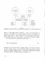
NJOY
The modular
used here
structure of NJOY is shown in Fig. 1.
in a very
restrictive
sense:
a module
The term “module” is
is a block of coding that
communicates with other modules only through logical units (the terms “tape” and
“file” will
module
be used
interchangeably
is essentially
in this
a freestanding program.
lay” version of the code.
report).
This means that every
Figure 1 illustrates the “over-
Here the NJOY level
consists of a simple executive
program for linking modules together and a set of utility subroutines available
to all modules.
Other
For example, the linking of
structures are possible.
modules could be handled by the normal sequencing capabilities of the operating
system; the NJOY utilities would then be made ava” lable to the loader as a relocatable library.
The restrictive definition of the term “module” used here
makes it possible to choose whichever of these two configurations
able for a particular
operating
is most suit-
system, makes it >asy to add new modules, and
protects a module against changes or repairs in another module.
A.
The Executive Program
This is the main program of the NJOY system.
It simply reads a module name
in free format and calls in the requested module.
module
contains
The first card read by any
the unit numbers for the various input and output files.
In
this way, the output of one module can be assigned to be the input of another
module,
thereby
linking the modules
to perform
Table I gives an example of the linking procedure.
2
the desired
processing
task.
NJOY
ENDF/B
PENDF
+
!
GENDF
\1
I
I
Main
program
I
‘t
Input
Module
?4
Work ing
Module
Olltput
MODER
RECONR
BROADR
UNRESR
MODER
DTFR
CCCCR
HEATR
THERMR
GROUPR
GAM INR
ERRORR
MATXSR
COVR
ACER
POWR
Basic structure of the
‘!
Module
Fig. 1.
NJOY code (overlay configuration).
TABLE I
EXAMPLES OF LINKING MODULES TOGETHER IN THE OVERLAY CONFIGURATION
[mount an ENDF/B tape on unit 20]
o
5
*RECONR*
20 21
[input 1ines for RECONR]
*GROUPR*
20 210
22
[input 1ines for GROUPR]
*OTFR*
22 23 21
[input 1ines for DTFR]
*STOP*
[DTF-format card images written on unit 23]
3
The main program also sets the page length (NPAGE) for blocked binary files
(see below) and assigns the unit numbers for system input and output.
NJOY ex-
pects these numbers to be less than 10 (the normal choice is 5 for input and 6
for output).
print
In a time-sharing environment,
it is often helpful to have a short
for the terminal while still preserving
printer.
the long listing for the system
Such an option is provided by IOPT=l.
This option changes the input
and output (NSHORT) to unit 7, which can be equivalence
The
final common
parameter
is IVERF, which
should be 4 to process
ENDF/B-IV
evaluations and 5 for ENDF/B-V.
The
input
the beginning
for the NJOY module are given as comment cards at
instructions
of the module.
They are reproduced
here for the convenience
of
the user (see also Vol. I: User’s Manual).
*
* ---INPUT SPECIFICATIONS
*
c
c
c
c
c
c
c
c
c
c
c
c
c
c
c
c
c
* CARD 1
*
IOPT
*
* CARD 2
*
IVERF
* CARD 3
*
MOPT
*
*
*
*
*
*
*
*
(FREE FORMAT)--------------------------*
INPUT OPTION
O FOR CARD INPUT AND FULL OUTPUT
1 FOR TERMINAL INPUT WITH SHORT OUTPUT ON TERMINAL
ENDF/B VERSION NUMBER (4 OR 5 ONLY)
SIX CHARACTER MODULE NAME DELIMITED WITH *
E.G. , *RECONR* (ONLY FIRST FOUR CHARACTERS ARE
USED . REPEAT FOR EACH MODULE DESIRED). USE
*sTop* T()TERMINATE PROGRAM.
SEE THE COMMENTS AT THE START OF EACH MODULE FOR
ITS SPECIFIC INPUT INSTRUCTIONS.
*
*
*
*
*
*
*
*
*
*
*
*
*
*
*
The example in Table I clarifies their use.
B.
Interface Files
Another requirement of a good modular system is that the input and output
files be in a common format so that modules can work with each other’s output in
a flexible way.
Since NJOY is
basically an ENDF/B processing code, ENDF/B-com-
patible formats (see Sec. X.D) were chosen for linking modules together.
put”
and “output”
modules
(see Fig. 1) can be specified
other formats (the “outside world”).
PENDF
4
However,
.
to the terminal (TTY).
to communicate
“Inwith
if the user desires, the RECONR
tape can be run through BROADR to produce a new Doppler-broadened
PENDF
b
tape
for GROUPR.
Many
other
combinations
files also provide for convenient
sequence.
For example,
are possible.
These
common-format
restarts at many points in the calculational
if a user is trying to produce pointwise cross sections
at 300 K, 600 K, and 900 K and runs out of time while working on 900 K, he can
save the partially
.
●
PENDf tape
completed
modules
use specially constructed
patible
with
the multigroup
and
groupwise
restart
from
600 K.
Multigroup
ENDF formats (GENDF) that are com-
output modules.
A GENDF
tape from GROUPR can be
saved in the NJOY data library, run through CCCCR to produce one output format,
and then run through MAT~SR for another output format.
In
NJOY, unit numbers from 20 through 99 are used for storing results or
linking modules,
be destroyed
units 10 through 19 are reserved for scratch files, which can
after
a module
has completed
its job, and units below 9 are re-
served for the system.
There
are special
utility
These routines can be modified
routines
to open, close, and reposition
files.
to adapt NJOY to a particular operating system.
OPENZ(LUN,NEW)
Open the unit = ABS(LUN).
If LUN > 0, use coded (formatted) mode, and
if LUN < 0, use binary mode.
10 < LUN < 20.
If
NEW=
1,
Destroy on close or job termination if
destroy
the
file
on
this
unit
(if
it
exists) and open a new file.
CLOSZ(LUN)
Close the file with unit = ABS(LUN).
REPOZ(LUN)
Reposition (rewind) the unit = ABS(LUN).
SKIPRZ(LUN,NREC)
Skip NREC records forward or backwards.
Caution:
Some systems
loops of backspace
these
operations
structures
for
have a call
option;
others can use
and dummy reads as given in the NJOY code.
work well
1/0
for this
files.
for systems
On
some
that
systems,
use “linked-list”
however,
Both
data
backspace
is
implemented as a rewind followed by forward dummy reads to the desired
location.
In such cases (for example, VAX), SKIPRZ must be recoded to
avoid calling BACKSPACE repeatedly.
This strategy
able
If call-
is similar to the approach standardized for FORTRAN-77.
open and close
operations
(or the equivalent)
are not available
on the
target system, a fixed set of units can be defined on a program card (CDC) or
job control
deck
simply
return
binary
1/0 in one part
c.
to
(IBM), and these routines can be replaced with versions that
the
calling
program.
Caution:
of the program
and coded
some units may be used for
(formatted)
1/0 in another.
Free-format Input
For a card-input
program,
free-form
input is convenient,
sharing environment,
it is almost essential.
been
the NJOY utilities
included
among
This
capability.
routine contains
a subroutine
Therefore,
to provide
but in a timeFREE has
a simple free-format
a machine-dependent
subroutine
input
PACK,
that
may have to be adapted to local conditions.
FREE(NIN, Z,NZA, NCW)
NIN
input logical unit containing free-format card images
Z(I)
dimensioned variable containing numbers decoded from input cards
NZA
on call, number of words desired
on return, number of words found
NCW
All
number of Hollerith characters to be loaded in each word, blank fill
to right
numbers read from the input cards are returned as real in Z.
program can convert selected numbers to integer
variables
are returned
machine.
If NCW
in integer
mode
form using the
as
required.
internal
N-bit
The calling
Hollerith
code of the
is larger than the number of characters per word, successive
locations of Z will be used.
Fields on the input cards are delimited by any character
other
purpose
( +,-,number,E,H,*,R,/).
For
exponent
fields,
not used for anthe
E must
be
●
present,
quired
and spaces are not allowed before the E. -Decimal
after
numbers.
Hollerith
fields
may
use
nHstring
points are not reor
*string*.
The
✎
character / terminates the input for one call to FREE (it may involve more than
one card) leaving any unread variables unchanged.
default variables
from the right.
lowing R to be repeated n times.
6
This feature is often used to
The nR specification
causes the number fol-
Some input examples follow.
W@
UM!i?l
12
12.
1.2E1
*U235*
4HU235
5R1.O
3R1. 1E6
1.2+1
1.2 El
4RU235 (does not right-justify)
Other examples will be found in input samples throughout this report.
FREE contains several parameters that may have to be changed when converting between
different
machines:
NBPC
is the number of bits per character
Hollerith data (6 on CDC, 8 on IBM), MACHWD
ters
in a machine
word
should be approximately
machine.
for
is the number of Hollerith charac-
(10 on CDC, 4 on IBM), and RNDOFF is a constant that
equivalent
to one bit in the last place for the target
The rest of the machine dependence is incorporated into FUNCTION PACK,
which inserts characters into words.
masking
for
CDC
machines,
Two versions are supplied: one is based on
and the other
uses one-byte
variables
and equiva-
lencing for IBM systems.
D.
ENDF Input-Output
The ENDF/B evaluated nuclear data files are well documented elsewhere,l but
for the convenience of the reader, some features of the format will be described
here.
ENDF/B
“tapes”
(MF), and “sections”
are subdivided
(MT).
internally
into “materials”
A MAT contains all data for a particular evaluation
for an element or isotope (for example, MAT1276
A “file” contains
versus
energy
(MAT), “files”
a particular
data; MF=15
is an evaluation
for 8-0-16).
type of data for that MAT: MF=3 is cross-section
contains
secondary
photon
energy
distributions.
A
“section” refers to a particular reaction [for example, MT=2 is elastic scattering and MT=107 is the (n$a) reaction].
MF, and MT values.
rial-end
Every record contains the current MAT,
Two materials are separated by a record with MAT=O (the mate-
or MEND record).
file-end or FEND record).
Two files are separated by a record with MF=O (the
Two sections are separated by a record with MT=O (the
section-end or SEND record).
Finally, the tape is terminated with a record with
MAT=-1 (tape-end or TEND record).
NJOY has a set of utility
subroutines
for locating desired positions on an
ENDF tape.
7
FINDF(MAT,MF,MT,NIN)
NIN
Search
backward
or
forward
for
the
first
record
with
this
MAT,MF,MT
TOSEND(NIN,NOUT1 ,NOUT2,A)
TOFEND(NIN,NOUT1,NOUT2,A)
TOMEND(NIN,NOUT1 ,NOUT2,A)
●
TOTEND(NIN,NOUT1,NOUT2,A)
Skip forward past the next SEND, FEND, MEND, or TEND Card on NIN.
NOUT1
and/or
NOUT2
are nonzero,
copy the records.
If
Input and output
files must be in the same mode.
The data on an ENDF tape are written in 7 different kinds of “structures”,
each of which
has a binary and a formatted form (the words “coded”, “formatted”,
and “BCD” will often be used interchangeably even though the actual representation
might
Hollerith
be
ASCII
display
code).
The
structures
are:
(1) TAPEID,
a
title for the tape; (2) CONT, a control record (includes SEND, FEND,
MEND, and TEND);
words;
or
(5) TAB1,
dimensional
of data items; (4) HOLL, a list of Hollerith
(3) LIST, a list
a one-dimensional
tabulation
tabulation
of data pairs; (6) TAB2, a two-
control record; and (7) DICT, an index (“dictionary”) to
the sections found in the MAT.
It should be noted that HOLL is a special case
of LIST and DICT is a special case of CONT.
In binary mode, each “structure”
is written as a single logical record as
follows:
TAPEIDIMAT,MF,MT/A(I),I=l,17]*
where MAT=tape number, MF=MT=O, and the Hollerith data are 16A4,A2;
CONTIMAT,MF,MT/Cl ,C2,L1,L2,N1,N2] ;
LIsTIMAT,MF,MT/cl,c2, Ll,L2,Nl,N2/
A(I),I=l,N1];
HoLLIMAT,MF,MT/cl,c2,
Ll,L2,Nl,N2/
A(I),I=l,N1];
*
In ENDF/B manuals, the slash is used as a logical divider. Replace it with a
comma and add parentheses when constructing a FORTRAN 1/0 list.
8
(0
where
MF=l,
MT=451,
and each
line of Hollerith
characters
is stored
in A as
16A4,A2;
TABl[MAT,MF,MT/cl,c2, Ll,L2,Nl,N2/
NBT(I),JNT(I),I=l,N1/
X(I),Y(I),I=1,N2],
.
where
NBT and JNT are the interpolation
table and Y(X) is the one-dimensional
tabulation;
.
TAB2[MAT,MF,MT/cl,c2 ,Ll,L2,Nl,N2/
NBT(I),JNT(I),J=l,NI],
table is to be used to control a series of N2 LIST or
where the interpolation
TAB1 structures that follow; and
DICTIMAT,MF,MT/O. ,O.,MFS,MTS,NCS,MODS] ,
where
there
is” a record for each section in the material
card count
(NCS) for that section.
(MFS,MTS) giving the
For ENDF/B-V, MODS indicates the revision
number for that section.
The ENDF/B procedure manuall explains
how these structures are combined to
represent various physical quantities.
In
order
to
that
keep
each
“structure”
words,
the
make
record
followed
these
records
length below
is broken
practical,
approximately
up into many
by MAT, MF, MT,
limits have been established
card
10 000 words.
images,
limit to the length of a data structure written
program
reading
reasonable
the data
size.
can normally
The MINX codez was
50%
of
eliminate
its
this
running
waste,
ENDF/B data structures.
of
intermediate
length
a
time coding
“blocked
(typically
is no in-
in BCD form because a
forced to use BCD formats to handle the
Analysis shows that this code uses more
and decoding
binary”
A structure
There
6 data
be coded to use the data in “pages” of
large tabulations found on PENDF tapes.
than
BCD mode,
each containing
and a line sequence number.
trinsic
In
format
BCD
has
formats.
been
In
developed
order
to
for the
is divided up into several logical records
about
300 words), each having the following
form:
[MAT,MF,MT, NB,NW/A(I), I=l,NW],
where NB is the number of words remaining in the data structure (the last record
has
NB=O).
record,
but
This
type of record
is also adaptable
is compatible
with
to paging methods.
the official
ENDF binary
The page size can be chosen
to optimize input/output rates for a particular computer system.
9
A set of utility subroutines has been devised to handle both blocked-binary
and paged-BCD input and output.
TPIDIO(NIN,NOUT,NSCR,A,NB,NW)
Read/write
the Hollerith
tape
identification
record
to/from
array A
(NB=O ,NW=17) .
CONTIO(NIN,NOUT,NSCR,A,NB,NW)
Read/write
a
control
.
record
to/from
A
(NB=0,NW=6).
Uses ACONT for
END cards.
ACONT(NOUT,NSCR)
Write an end record on the desired units.
LISTIO(NIN,NOUT,NSCR,A,NB,NW)
Read/write the first record or page of a list record to/from A.
If NB
is not zero, continue with MOREIO, as illustrated in Examples 1 and 2
below.
HOLLIO(NIN,NOUT,NSCR,A,NB,NW)
Read/write the first record or page of the Hollerith descriptive data
(MF1,MT451) to/from A, taking account of the 16A4,A2 format needed in
BCD mode.
If NB is not zero,
use MOREIO.
TABIIO(NIN,NOUT,NSCR,A,NB,NW)
Read/write the first record or page of a TAB1 structure.
8
zero, use MOREIO.
If NB is not
TAB210(NIN,NOUT,NSCR,A,NB,NW)
Read/write a TAB2 structure (NB=O).
DICTIO(NIN,NOUT,NSCR,A,NB,NW)
Read/write the entire material dictionary (really an index) to/from A.
On entry,
NW
is the number of entries in the dictionary.
MOREIO is
not used.
MOREIO(NIN,NOUT,NSCR,A,NB,NW)
b
Read/write continuation records or pages to/from the array A.
Returns
NB=O after processing the last record or page.
.
CXFP(X,F,S,N)
This routine is used by some of the other ENDF/B routines to prepare
formatted
numbers
output
are
without
output
normal
as A1.23456tNN
size of the exponent.
10
the
FORTRAN
“E”.
or tl.234567tN,
Floating-point
depending
on the
In these calling sequences, the unit numbers can be positive, negative, or
zero.
mode,
Positive
numbers
and zero means
sequence
is not used.
mean
BCD
mode,
negative
the file corresponding
All of these
numbers
mean blocked-binary
to this position
in the calling
routines use one area of label led common
COMMON/CONT/Cl,C2, L1,L2,N1,N2,MAT,MF ,MT,NS,NSP,NSC
●
.
where Cl through MT have their usual ENDF meanings,
for NIN,
NSCR.
NS is
NSP is the sequence number
the sequence number of NOUT, and NSC is the sequence number for
Two examples may help to make clear the use of these routines.
Example 1.
Read All Data
LOC=l
CALL TABIIO(NIN,O,O,A(l),NB,NW)
10 IF (NB.EQ.0) GO TO 20
LOC=LOC+NW
CALL MOREIO(NIN,O,O,A(LOC),NB,NW)
GO TO 10
20 [process data in A]
Example 2.
Pagi~
CALL TABIIO(NIN,O,O,A(l),NB,NW)
10 [process this page of data in A]
IF (NB.EQ.0) GO TO 20
CALL MOREIO(NIN,O,O,A(l),NB,NW)
GO TO 10
20 CONTINUE
●
When NIN is BCD, paging is automatic.
Positive and negative unit numbers can be
mixed in TPIDIO, CONTIO, LISTIO,
when mode conversion is desired.
4
The advantages
etc.,
of the blocked-binary
mode are demonstrated
in Table II
for
several characteristic processing tasks.
E.
Buffered Binary Scratch Storage
During the execution of a program, there are often times when large amounts
of data need to be stored in mass storage temporarily.
In order
to make such
scratch storage as efficient as possible,
routines that automatically
buffer such
NJOY includes a pair of utility sub-
data
through
fast
memory to disk
and/or
1arge core memory (LCM).
LOADA(I,A,NA,NTAPE,BUF,NBUF)
FINDA(I,A,NA,NTAPE,BUF,NBUF)
where
I
=
data
point
1<0 flushes
array
number (I must increase,
the
containing
fast
memory buffer
data
1=1 causes
except
a rewind
and
to mass storage)
to be stored or destination
of data to be
read
NA
=
number
of words
to be transmitted
NTAPE =
logical unit number of disk file
BUF
fast-memory buffer array
=
NBUF =
(must be the same for all I)
length of buffer array
When a point is to be saved, LOAOA stores it in BUF.
is automatically
to see whether
dumped to disk.
When BUF becomes full, it
When a point is to be retrieved, FINDA checks
the desired point is in BUF.
until the desired point is in memory.
If
not, it reads through the disk
It then returns the desired point.
When
NA is small, using LOADA/FINOA reduces the number of 1/0 operations dramatically.
TABLE II
EXAMPLESOF EFFICIENCY GAINS OBTAINEDWITH BLOCKED-BINARYINPUT
BCO
Test
235u
Doppler broadening
235u
P3 elastic matrix
2351j
(n,2n) matrix
BB
72.1
169.
4.99
10.9
4.51
.838
46.5
139.
Iron Doppler broadening
b
Sometimes
In such cases,
it
is
necessary
to
find
use
SCANA(E,IP,NP,NA,NTAPE,BUF,NBUF)
12
a particular
part
of the
buffered
data.
where E is a value for the first of the NA words, and 1P points to part of the
data whose first word is either equal to E or is the first value less than E.
F.
Dynamic Storage Allocation
In many large computer codes; storage requirements may change continually
throughout
the execution
available memory,
of a problem.
If maximum
use
is to be made of the
it is necessary to reallocate and repack storage in response
to the requirements of the calculation.
In NJOY, these functions are handled by
the STORAG package of 4.subroutines.
STORAG(IAMAX,NIDMAX,IPR,A)
Initialize variably dimensioned
the container
maximum
array A.
number
of data
dynamic storage allocation system for
IAMAX = length of container array.
NIDMAX =
identifiers that will be needed at one time.
IPR = print flag (normally O, use 1 to suppress most routine messages).
RESERV(ID,NWORDS,INDEX,A)
Reserve
NWORDS in A for the data set identified by ID.
left-adjusted
Hollerith
ID can be a
name or a number less than or equal to 9999.
If
Space will be allocated at the top of A if possible.
insufficient
space is available, A will be repacked, and another attempt to reserve
space will be made.
words to this ID.
If NWORDS = -1, repack A and assign
all available
INDEX points to the first word for data set ID in A.
RELEAS(ID,NWORDS,A)
Release all but NWORDS of the space assigned to ID in A.
deletes
this
entries
above
ID.
If NWORDS
is less than zero,
it are deleted.
Note
that
this
repacking
NWORDS = O
ID and all ID
of A only takes
place when the released space is really needed (see RESERV).
FINDEX(ID,INDEX,A)
Find the index for the data set ID.
Using FINDEX is good practice if
there is any chance that A might have been repacked since RESERV was
cal led.
The NWORDS=-1 option in RESERV is useful when the number of words in a data
set is not known in advance -- an example,
13
Nw=-1
CALL RESERV(3HSIG,NW,LSIG,A)
READ(NIN)NW,(A(LSIG+I-l),I=l,NW)
CALL RELEAS(3HSIG,NW,A)
STORAG prints out routine messages
the use of memory.
(if IPR=O) so that the user can monitor
The following example from THERMR illustrates several char-
*
acteristics of STORAG.
.
1
2
STORAG
ID SCR
ID BUFO
ID BUFN
3
4
5
6
7
8
9
ID STK
ID FL
XX FL
XX STK
ID E
.
.
.
10/20000
1/ 2050
2/ 3050
3/ 4050
4/ 4110
5/19963
406
-1
4/ 4095
In line 1, STORAG is initialized with 20 000 words of core for up to 10 identifiers.
The
In lines 2, 3, 4, and 5, space is reserved for SCR, BUFO, BUFN, and STK.
number
before
the slash is the ordinal number assigned to the identifier,
and the second number is the total amount of storage used so far.
space
for
STORAG
message
were
FL was
table were
would
needed
reserved with
allocated.
have appeared
NWORDS=-1.
If
here.
repacking
Therefore,
had been
In line 6,
20 000 words
necessary,
less the
a “REPACKING”
The program determined that only 406 words
for FL, and the remainder of the storage was released in line 7.
The maximum storage used to this point was 4110 + 406 = 4516.
Farther on, the
code was finished with STK and FL, and both were released by a single call with
NWORDS=-1
as indicated by line 8.
assigned.
Finally, line 9 shows a new identifier being
Note that position 4 in the STORAG table was reused.
The STORAG system is compact and easy to use.
The overhead required to use
it is very small unless frequent repacking is required.
G.
ENDF/B Utility Routines
There
so many
14
are several
other modules
operations
that
performed on ENDF/B data that are needed in
it is practical
to put them
into the NJOY level.
TERP1(X1,Y1,X2,Y2,X,Y,I)
Interpolate for y(x) between yl(xl) and y2(x2) using the ENDF/B interpolation
y
law I [1=1 means y=yl,
1=2 means y is linear in x, 1=3 means
is linear in in(x), 1=4 means
In(y) is linear in x, and 1=5 means
In(y) is linear in In(x)].
TERPA(Y,X,XNET,IDIS,A,IP,IR)
Interpolate
for y(x)
in the TAB1 structure
searches for the correct
The routine
range starting from 1P and IR
interpolation
(initialize to 2 and 1 for first call).
value in the tabulation.
in array A.
It returns XNEXT, the nextx
IDIS is set to 1 if there is a discontinuity
at XNEXT, it is zero otherwise).
GETY1(X,XNEXT,IDIS,Y1,ITAPE,A)
GETY2(X,XNEXT,IDIS,Y2,1TAPE,A)
Find y(x)
in a TAB1
structure
starting
at the current
ITAPE by paging the data through array A.
location
on
GETY1 and GETY2 are iden-
tical for occasions when two different tapes are being searched at the
same time.
XNEXT and IDIS behave as in TERPA.
least NPAGE+50 words
in length.
The array A must be at
These routines are normally used to
retrieve cross sections from MF=3.
GRAL(XL,YL,XH,YH,X1,X2,1)
This function returns the integral from xl to X2 of an ENDF/B function
with interpolation
law I (see TERP1).
XL, YL, XH, and YH are the low
and high limits of the interpolation panel.
INTEGA(F,X1,X2,A,IP,IR)
Integrate
the TAB1
automatically
function stored
determines
The routine
in A from xl to x?.
the correct
interpolation
law-for each panel
or fraction of a panel and uses GRAL to compute each part of the integral .
calls,
Set IP=2 and IR=l
the
previous
on the first call to INTEGA.
values
of
In subsequent
1P and IR will usually provide a good
starting point for searching in the TAB1 structure.
H.
Code Conversion
Standardization
where
it is possible
ever,
by using
of
fairly
the
computer
industry
has not yet
to write a truly machine-independent
reached
the point
FORTRAN code.
simple commands and isolating some functions
How-
in utility
15
subroutines,
it is possible to minimize
the number of changes that have to be
made to convert a typical CDC code to an IBM machine.
changes can be made automatically
App. D).
Furthermore, many of the
with a simple preprocessing code (see Vol. I,
NJOY uses the following trick:
.
.
.
CCDC
●
INTEGER H(5)
CCDC
CIBM
c
REAL*8 H(5)
CIBM
.
●
.
The variable H is intended to hold Holler th data.
To convert from CDC to IBM,
simply add a C in column 1 of every card image bracketed by CCDC cards and remove the C from column 1 of every card ima!e bracketed by CIBM cards.
Machine-dependent
discussed above.
aspects
of free-form
input and
interface 1/0 have been
Several other conversion problems are discussed here.
BANNER
This
subroutine
prints
the NJOY banner
on the output
file.
It in-
cludes a user field LAB, which should be changed to properly identify
the user’s installation.
used to inciicate
Wtljctl
remove CALL MACH(MX)
The date
It also includes a variable MX, which can be
machine was used at large COmpUtitKJ Centers;
if a corresponding
and time-of-day
capability
is not available.
routines used here may have to be replaced
with local equivalents.
*
ERROR
This
subroutine
should
result in a fatal error exit and must be ad-
justed to reflect the local system.
Special features such as trace-
back information or saving files for later analysis can be performed
here.
TIMER
This
routine
will
have to be revised
given is appropriate for CDC machines.
16
in many
systems.
The coding
,
SIGFIG
Because of the many comparisons and searches that it makes, NJOY often
has
to match
significant
exactly
number
two numbers
bits.
equal
of
to
This
routine
is
each ‘other by
digits
and
from nonterminating
.
that are different
removing
intended
truncating
any
binary fractions.
only
to
the
in the few
make
such
numbers
low-significance
This problem
least
numbers
to a given
junk
resulting
is not so common
on short-word-length machines, but it might still be necessary to convert this routine for some machines.
I.
Error Messages
NJOY***ILLEGAL
ENDF/B VERSION NUMBER
Only 4 and 5 are allowed.
ENDF/B-111 data can be processed with IVERF=4.
NJOY***ILLEGAL OPTION
Use O for card-image input or 1 for TTY.
NJOY***ILLEGAL MODULE NAME
Check spelling, and check for missing (/) or incorrect item counts in the
preceding module.
Only the first four characters of each name are used.
OPENZ***ILLEGAL
CLOSZ***ILLEGAL
UNIT NUMBER
UNIT NUMBER
Units less than 10 are reserved for the system.
TOMEND***MODE CONVERSION NOT ALLOWED
TOFEND***MODE CONVERSION NOT ALLOWED
TOSEND***MODE CONVERSION NOT ALLOWED
Input and output units must both be binary or both be BCD.
FINDF***MAT---MMT--MT---NOT
ON TAPE
Desired section cannot be found.
STORAG***STORAGE
There
EXCEEDED
is not enough
storage
allocated
to hold even
the directory table.
RESERV***STORAGE
EXCEEDED. NEED---MORE WORDS FOR ID----
Container array is not large enough to hold desired data, even after repacking. The message gives an estimate of the additional storage required.
RESERV***ID--- ALREADY DEFINED
An ID must be released before being reassigned.
RESERV***POINTER
SEQUENCE ERROR
.
The directory
clobbered.
RESERV***EXCEEDED
at
the
start
of
the
container
array
has
probably
been
MAXIMUM NUMBER OF ID-S
See NIDMAX in STORAG.
RESERV***REQUESTED
RESERVE OF ZERO WORDS
Check coding that called RESERV.
RELEAS***ID---NOT
DEFINED
Check coding and spelling.
RELEAS***ATTEMPT TO RELEASE MORE WORDS THAN STORED
Self-explanatory.
FINDEX***ID---NOT
Check coding.
DEFINED
Check coding and spelling.
J.
References for NJOY
1.
R. Kinsey, “ENDF-102, Data Formats and Procedures for the Evaluated Nuclear
Data Files, ENDF,” Brookhaven National Laboratory report BNL-NCS-50496
(ENDF 102) 2nd. Ed. (ENDF/B-V) (October 1979).
2.
C. R. Weisbin, P. D. Soran, R. E. MacFarlane, D. R. Harris, R. J. LaBauve,
J. S. Hendricks, J. E. White, and R. B. Kidman, “MINX, A Multigroup Interpretation of Nuclear X-Sections from ENDF/B,” Los Alamos Scientific Laboratory report LA-6486-MS (ENDF-237) (1976).
18
-1
I
x.
RECONR
The
RECONR
resonance
parameters
interpolation
,
module
is
used
to reconstruct
and to reconstruct
schemes.
sections
cross
sections
from ENDF/B
The output is written as a pointwise-ENDF
from
nonlinear
tape (PENDF)
with all cross sections on a unionized energy grid suitable for linear interpolation to within a specified tolerance.
.
cross
resonance
or inelastic)
at
are reconstructed
all energies.
The
material dictionary
resonance
Redundant reactions (for example, total
to be exactly equal to the sum of their parts
parameters
are removed
from File 2, and the
is corrected to reflect all changes.
Resonance reconstruc-
tion uses methods based on RESEND1 and linearization
for MINX.2
uses the method developed
RECONR has the following advantages over the RESEND module of MINX:
.
Efficient use of dynamic storage allocation and a new stack structure allow
large problems to be run without the use of secondary overlays.
.
The unionized grid improves
ibility of the output.
.
A correct material dictionary is provided.
.
Approximate $x Doppler broadening
for narrow-resonance materials.
.
A resonance-integral
A.
ENDF/B Cross Section Representations
the accuracy,
may
usefulness,
and ENDF/B compat-
be used to speed up reconstruction
criterion is added to the normal linearization criterion, in order to reduce the number of points added to the tabulation to
represent “unimportant” resonances.
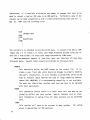
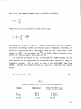
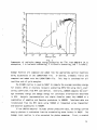
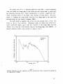
A typical cross section derived from an ENDF/B evaluation is shown in Fig.
1.
The
low-energy
cross sections are “smooth”.
They are described
in File 3
(see IX.D for a review of ENDF/B nomenclature) using cross-section values given
,
on an energy grid with a specified law for interpolation between the points.
In
the resolved resonance range, resonance parameters are given in File 2, and the
.
cross sections for resonance reactions have to be obtained by adding the contributions of all the resonances
gies comes
fined.
the unresolved
to “backgrounds” from MF3.
region where
explicit
At still higher ener-
resonances
are
no longer de-
Instead, the cross section is computed from statistical distribution of
resonance parameters
given in File 2 and backgrounds
the highest energies, the smooth MF3 representation
from File 3.
Finally, at
is used again.
19
“o
~-l
‘-b
c
.
L
s
.$%
b
~d
c1
i%
m
VI
o
b%
00
-10-3
10-2 10-’ 10°
10’
10’
10’
Ener~v
(eV)
104
ld’
106
10’
Fig. 1.
A typical cross section reconstructed from an ENDF/B evaluation using RECONR.
The smooth, resolved, and unresolved energy regions use different representations of the cross sections.
For medium-mass
isotopes, the unresolved range is usually omitted.
For the
lightest isotopes, the resolved range is also omitted, the resonance cross sections being given directly in the “smooth” format.
ent
resonance
parameter
representations
are
In addition, several differ-
allowed.
It
is the
purpose
of
RECONR to take all of these separate representations and produce a simple crosssection-versus-energy
B.
representation such as that shown in Fig. 1.
Unionization and Linearization Strategy
Several
of
cross sections
the
cross
sections
found
in ENDF/B evaluation
are summation
(for example, total, inelastic, and sometimes n2n and fission),
and it is important that each summation cross section be equal to the sum of its
parts.
However,
if the partial
cross sections are represented with nonlinear
interpolation schemes, the sum cannot be represented by any simple interpolation
20
law.
A typical case is the sum of elastic scattering (MT2 interpolated linearly
to represent
represent
.
a constant)
I/v).
The total cross
section
cannot
be represented
log-log to
accurately
by
either scheme unless the grid points are very close together.
This effect leads
to significant
and to splitting
balance
errors
problems in continuous-energy
Furthermore,
.
and radiative capture (MT102 interpolated
integrated
(see BROADR),
in several ways.
easily,
and,
cross
finally,
transport
codes
Monte Carlo codes.
the use of linear-linear
E) can be advantageous
can be
in multigroup
interpolation
(that is, a linear in
The data can be plotted easily, they
sections can be Doppler broadened efficiently
linear data can be retrieved
efficiently
in con-
tinuous-energy Monte Carlo codes.
Therefore,
RECONR puts all cross sections on a single unionized grid suit-
able for linear interpolation.
one pass
pass
As described in more detail below, RECONR makes
through the ENDF/B material to select the energy grid, then a second
to compute cross sections on this grid.
Each cross section on the PENDF
tape (except for the redundant summation cross sections) is exactly equal to its
ENDF/B value.
The summation cross sections are then obtained by adding up the
partials at each grid point.
While RECONR is going through the reactions given in the ENDF/B evaluation,
it also checks
the
reaction
thresholds
against
ratio to the neutron (AWR) given for the reaction.
threshold > %
is not satisfied,
i
If the condition
Q
(1)
the threshold energy
s moved up to satisfy the condt ion
and
an informative message is printed if the change exceeds O.I.%.
If
,
the Q value and atomic weight
desired, the unionized grid developed
plemented
with
“user
matically
adds
1.E-5 eV,
already present.
grid
points”
given
0.0253 eV,
and
from the ENDF/B file can be sup-
in the input data.
20 MeV
to the grid
The
code auto-
if they are
not
c.
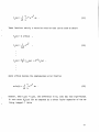
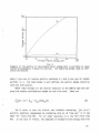
Linearization and Reconstruction Methods
Linearization
(LUNION)
and resonance reconstruction
(RESXS) both function
by inserting new energy grid points between the points of an original grid using
an
“inverted
stack”.
simple
example
values.
For
grid.
For
shown
The
in Fig. 2.
linearization,
reconstruction,
resonances.
general
The
stack
concepts
The
are
illustrated
with
a
stack is first primed with two starting
they will
they
involved
be two adjacent
will
usually
is said to be
be
the
points
peaks
on the original
of
two
.
adjacent
inverted because the lower energy is at
.
the “top” (1=2).
This
interval
or
“panel”
is
now
divided
into two parts,
and the cross
section computed at the intermediate point is compared to the result of linear
interpolation
between
the
adjacent
points.
If the
two
values
do not agree
within various criteria, the top of the stack is moved up one notch (1=3), and
the new value is inserted (1=2).
The code then repeats the checking process for
the new (smaller) interval at the top of the stack.
until convergence
section
The top of the stack rises
is achieved for the top interval.
The top energy and cross
are then saved on a scratch file, the stack index is decremented,
the checks
are repeated.
This process
and
is continued with the top of the stack
rising and falling in response to the complexity of the cross section until the
entire panel AE has been converged
bounds of the next panel.
(1=1).
The stack is then reprimed with the
The process continues
until the entire energy range
for linearization or reconstruction has been processed.
This new stack logic enables a panel to be divided into parts as small as
AE/2n where”n is the stack size (currently 20), and several different cross sections (elastic, capture, fission) can easily be stored in arrays of this size.
By contrast,
RESEND used several arrays 500 words long and sometimes ran out of
storage while subdividing between resonances.
Intervals are subdivided differently for linearization and resonance recon1
struction.
RESEND.
used.
In the
latter case,
For linearization
Analytic
formulas
the
interval
the method
are
used
is simply divided
developed
to choose
in half as in
by D. R. Harris for MINX2 is
the optimum
intermediate
point;
this point turns out to be the energy value where the slope of the actual interpolation function equals the slope of the linear interpolate.
vided for each of the nonlinear ENDF/B interpolation laws: ois
in(a) is linear in E; and in(o) is linear in in(E).
22
Formulas are prolinear in in(E);
,
VI
m
0
C5
I
I
1
1 I
I
I
1
Energy +
Stack
Version
1
2
1
2
3
I
432
1
1
5432
1 I I
432
1 I
3
4
5
6
7
8
9
10
I
Energy Grid Now Stored in Stacka
1
I
32
1
2
I
1
1
1
1
I
I
I
I
2
I
321
I
I
4321
I I I
321
I I
21
1
i
1
I
1
I
1
I
Result of Convergence Test
on Lowest-Energ y Segment
Not converged, add midpoint
II
II
Converged, wr te lowest E to d sk.
11
II
Not converged, add midpoint
II
I
I
Converged, write lowest E to disk.
II
I
11
Not converged, add
midpoint
12
Converged, write lowest E to disk.
II
13
,
14
Finished. Read energy of next
resonance and repeat.
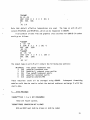
aNumbers above energy markers indicate location in the stack.
stack may be as large as 20.
Total length of
Fig. 2.
Inverted-stack method used in LUNION and RESXS.
23
The
convergence
criterion
used for linearization
is that the linearized
cross section at the intermediate point is within the fractional tolerance ERR
of the actual
cross section specified by the ENDF law.
More complicated
cri-
teria are used for resonance reconstruction.
There
are two basic problems
that arise if a simple fractional tolerance
test is used to control resonance reconstruction.
the energy
First, as points are added to
rounded to the same number when a formatted output file is produced or when the
machine-dependent
limit for decimal
clearly
sense
makes
reached.
no
to
single-precision
continue
to
add
grid
accuracy
points
is reached.
after
this
limit
It
is
Through the use of dynamic format construction, the energy resolution
available for formatted NJOY output is 7 significant figures (that is, tl.234567
+n)
rather
than the usual 5 or 6 (see Section X.D).
(32-36 bits per word), the limit set by precision
figures.
files
on Ilshort-wordlimachines
is also about 7 significant
On “long-word” machines (typically 60-64 bits per word), binary output
can
be
used,
and
NJOY can produce
up
to
15
significant
figures
if
necessary.
Significant
figure control
is implemented
as follows:
each intermediate
energy is truncated to NDIGIT significant figures before the corresponding cross
sections
are computed,
and
if the resulting
number is equal to either of the
adjacent values, the interval is declared to be converged.
Thus, no identical
energies are produced, but an unpredictable loss in accuracy results.
in the
area
of this
interval
is certainly
less
than
0.5*Ac7*AE, so this
The error
value
is
added to an error estimate and a count of panels truncated by the significant
figure check is incremented for a later informative diagnostic message.
The
resonance
second
basic problem alluded to above is that a very large number of
grid points
arise
from straightforward
resonance cross sections of some isotopes.
linear reconstruction
of the
Many of these points come from nar-
row, weak, high-energy resonances, which do not need to be treated accurately in
many applications.
%
an example, the capture and fission resonance
integrals
important for thermal reactors must be computed with a l/E flux weighting.
the resonance reconstruction
of processing,
However,
the resonance
if the high-energy
tolerance
is set high (say l%] to reduce the cost
integrals will
resonances
If
be computed
(whose importance
to only %
accuracy.
is reduced by the l/E
weight and the l/v trend of the capture and fission cross sections) are treated
with less accuracy than the
24
,
grid, adjacent energy values may become so close that they will be
ow-energy resonances, then it is likely
.
that one can achieve an overall reduction
puting
cost),
or
increased
Since l/E weighting
accuracy
in the number of points (hence com-
in computed resonance integrals, or both.
is not realistic in all applications
(for example, in fast
reactors), user control of this “thinning” operation must be provided.
Based on these arguments,
problem
of very
the following approach was chosen to control the
large files.
First, panels
are subdivided
and capture cross sections are converged to within
These two tolerances
and
0.5%,
example,
panel
to
until the elastic
ERRMAX, where ERRMAX ~ ERR.
are normally chosen to form a reasonable band, such as 10%
ensure
tQat
for plotting).
all
resonances
are
treated
at
least
roughly
(for
If the resonance integral (1/E weight) in a particular
is large, the panel is further subdivided to achieve an accuracy of ERR
(say 0.5%).
interval
value
However, if the contribution to the resonance integral from any one
gets
small,
the
interval will
be declared
converged,
of the cross section will end up with some intermediate
again,
the contribution
than 0.5*Ao*AE.
to the error in the resonance
and the
local
accuracy.
Once
integral should be less
This value is added into an accumulating estimate of the error,
and a count of panels truncated by the resonance integral check is incremented.
The problem with this test is that RECONR does not know the value of the
resonance
actual
integral
allowed
the resonance
fractional
integral
ERRINT=ERR/lOOOO
barn
in advance,
with
choice.
vary
The
error
error
in
resulted
would
from
from a few barns
integral
the
parameter
integral.
ERRINT
Instead,
per grid point (barns/point).
ERR=O.001
if 10000 points
integrals
so the tolerance
is not the
it is more
like
Thus, a choice of
limit the integral error to about 0.001
reconstruction.
Since important resonance
to a few hundred barns, this is a reasonable
check can be suppressed by setting ERRINT very small or
ERRMAX=ERR.
When resonance reconstruction
possible
resonance
integral
check
covers
integral
over
several
the unresolved
range,
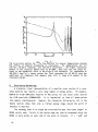
is complete, RECONR provides a summary of the
error
due to significant
coarse
energy
if present.
bands
figure reduction and the
(see Fig. 3).
The parameter
The last band
NDIGIT and the
param-
eters ERRMAX and ERRINT, taken together, should be considered as knobs that can
increase or decrease
the errors
in their
respective
columns to get an appro-
priate balance of accuracy and economy for a particular application.
25
D.
Resonance Representations
RECONR
code
1
with
uses the resonance
three
changes:
a
formulas
more
as implemented
efficient
in the original RESEND
calculation
of multilevel
Breit-
Wigner cross sections developed by C. Lubitz of the Knolls Atomic Power Laboratory (General Electric Co.) and coded by P. Rose of the Brookhaven National Laboratory,
the addition
Doppler-broadening
of competitive widths
calculation
for
introduced for ENDF/B-V, and a $X
single-level
Breit-Wigner
and
Adler-Adler
resonance shapes.
An expanded discussion of the following formulas can be found
3
in the ENDF/B-V format manual.
The
subroutine
that
computes
single-level
Breit-Wigner
cross
sections
(CSSLBW) uses
(2)
‘f
‘f
‘Z(J
—*(e,x)
r mrt
(3)
,
(4)
(5)
where On, a
and Op are the neutron (elastic), fission, radiative capture,
f’ ‘y’
and potential scattering components of the cross section arising from the given
resonances.
added
There
to these
can be “background”
values
to account
cross
sections
for competitive
in File 3 that must be
reactions
such as inelastic
scattering or to correct for the inadequacies of the single-level representation
with
regard
to multilevel
effects or missed resonances.
The sums extend over
all the resolved resonances r that may belong to different
(L and AJ in the code).
26
.
spin sequences J2, J
Each resonance is characterized by its total, neutron,
.
ESTIMATED
MAXIMUM ERROR DUE TO
RESONANCE INTEGRAL
CHECK (ERRMAX,ERRINT)
ANO SIGNIFICANT
FIGURE TRUNCATION
(NDIGIT)
UPPER
ENERGY
1.55E+02
4.96E+02
1.63E+03
5.20E+03
1.73E+04
5.62E+04
1.78E+05
4.00E+05
ELASTIC
INTEGRAL
PERCENT ERROR
RES-INT
SIG-FIG
7.45E+oo
5.94E+O0
4.12E+oo
6.49E+O0
9.66E+O0
4. 2oE+O0
3.50E+o0
.000
.000
.000
.000
.001
.004
.008
CAPTURE
INTEGRAL
PERCENT ERROR
RES-INT
SIG-FIG
2.82E-02
1.71E-01
6.80E-03
1.61E-02
1.74E-02
1.19E-02
5.64E-03
0.000
0.000
0.000
.000
.000
.009
.007
.009
.002
.149
.134
.200
.216
.257
0.000
0.000
0.000
. C08
.097
4.284
5.265
POINTS
AOOED BY RESONANCE RECONSTRUCTION
= 12309
POINTS
AFFECTEO BY RESONANCE INTEGRAL
CHECK =
6969
1262
POINTS
AFFECTED BY SIGNIFICANT
FIGURE
REOUCTION
=
POINTS
REMOVEO BY BACKTHINNING
=
201
FINAL
NUMBER OF RESONANCE POINTS
= 12749
●
*.********.
Sample
●
*************
of RECONR
●
*************
●
*************
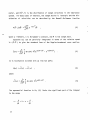
Fig. 3.
resonance-integral and
●
******8******
significant-figure
fission, and capture widths (I_t,rn, r f, ry) and
162.036S
*******
error
summary.
ts maximum value (SMAX = Om/rt
in the code)
o
_
m
4n
‘n
~2gJ7’
(6)
where gJ is the spin statistical factor
ZJ+l
gJ=—
I is
(7)
41+2 ‘
the total spin SPI
given
in File
2,
and k is the neutron wave number that
depends on incident energy E and the atomic weight ratio to the neutron for the
isotope, AWRI, as follows:
27
k = (2.196771
x 10-3)
The neutron width
/g&
fi
.
(8)
in these equations is energy dependent due to the penetration
factors Pg; that is,
Pg(E) r
‘n(E) ‘~”
Po=p
(lo)
,
pi=<
,
l+p
‘2
(9)
‘
(11)
and
.-d_
,
9+3p2+p4
(12)
where Er is the resonance energy and p = ka depends on the channel radius (RA)
a = 0.123 AWR11/3 + 0.08
.
(13)
The phase shifts are given by
A
$-J=P
(14)
~
A
- tan-l;
@~=P
,
and
(15)
,
(16)
A
02=
P-tan
-l&
3-p2
28
A
where
p
=
ka
depends
on
the
scattering
components of the cross section are the
radius
AP
actual
line shape functions * and x.
given
in
the
file.
The final
At
zero temperature,
*=-L
(17)
1+X2‘
~=-E_-
1+/ ‘
.
(18)
and
(19)
2(E-E;)
x=
Y
‘t
sg(lErl)
E;=Er+
in
terms
of
- SQ(E)
2(Pl(lErl)
the
So=o
shift
l-n(lErl)
(21)
Sl=-+
,
and
(22)
l+f)
2
Is+;p ~
9+3p +p
To go to higher
f)=
(20)
factors
,
S2 = -
,
temperatures,
(23)
define
‘t
9
J=
(24)
4kTE
AWRI
29
where
k is the Boltzman constant and T is the absolute temperature.
The line
shapes $ and x are now given by
(25)
(26)
in terms of the complex
probability
function
(see QUICKW, WTAB, and W, which
came from the MC2 code4)
2
W(z) = e-z
=—
where
:
erfc(-iz)
~-m <dt
z = x + iy.
BROADR)
because
(27)
‘
The ~
method is not as accurate as kernel broadening
the backgrounds
broadened,
and
neglected;
however,
terms
important
the ~
(which
for
method is
are sometimes
energies
less
less
expensive
version of RECONR includes Doppler broadening
for
the
quite
(see
complex) are not
than
about
than
BROADR.
16kT/AWRI
are
The current
single-level Breit-Wigner
representation only.
a
The
section
Lubitz-Rose
(CSMLBW)
is
method
formulated
On(E) = Z CJn9(E)
Q
30
,
used
for
calculating
multilevel
Breit-Wigner
cross
as follows:
(28)
I
Onl(E) = ~
: gJ 1 - unJ(E)
and
(29)
ir
Zioy - ~
nr
~ E; - E - ir#2’
UnJ(E) = e
(30)
,
●
where
the
symbols
are
the
same
as
those
used
above.
Expanding
the
complex
operations gives the actual formula used
where
sums
the
over
r are
limited to resonances
in spin sequence .!2,J.
The
fission and capture cross sections are the same as for the single-level option.
The allowed values of J for this sum are limited to the range
where S is the magnitude of the channel spin 1-% and I is
The
total
,
multilevel
cross
sections
~t(E) = ~
Adler-Adler
are
sin2$o +%
given
representation
the target spin (SPI).
is defined
for 2=0
only.
The
by
{Z~[(Gcos2@o
v
r
rr
+Hsin2$O)
r
$(0,x)
●
+ (Hrcos2@0 - Grsin2$O) x(6,x)]
+ Al + A2/E + A3/E2 + A4/E3 + BIE + B2E2]
,
(32)
where
Pr-E
(33)
x.—
v’
r
and where v r is the resonance half-width (corresponds to r/2 in the Breit-Wigner
notation), pr is the resonance energy, Gr is the symmetric total parameter, Hr
is the asymmetric
total parameter,
and the Ai and Bi are coefficients
of the
total background correction.
The fission and capture cross sections both use the form
a(E)=@
x
2
r
[Gr$(&x)
+ tir@,x)]
‘r
+ Al + A2/E + A3/E2 + A4/E4 + BIE + B2E2]
where
the values of G, H, Ai ,
and
Bi
(34)
,
for the desired reaction are
appropriate
used.
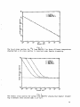
Doppler
broadening
can be applied as for the SLBW case, except note that
rr in Eq. (24) must be replaced with 2vr.
sections
are
more
accurate
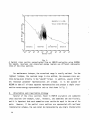
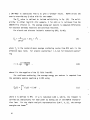
smoother.
However,
accurate.
An
than
cross
example
of
SLBW
sections
the
cross
below
agreement
Doppler-broadened
sections
about
between
because
background
the
16kT/AWRI
~
Adler-Adler cross
will
broadening
still
and
be
the
is
in-
more
accurate kernel broadening (see BROADR) is shown in Fig. 4.
Infinitely
puted
in CSUNR1
distributions
are
not
solved
dilute
or CSUNR2
from File 2.
temperature
resonance
cross
sections
using average
resonance
With the approximations
dependent;
data
in the unresolved energy range are com-
generated
therefore,
using
the
results
TEMPR > 0.
on the single-level approximation with interference:
32
parameters
and probability
used, these cross sections
are
a
good
match to re-
The formulas used are based
—
---------
Reconr only
Broadr
Z Difference
.
,
/-.
...
~.,
l.,
------ --- ——--—
--..-,,
b“4,!.\lA4,$)u(+)&A*.v-
2.5
1.5
1.0
Energ~
3.0’
(eV)
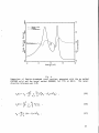
Fig. 4.
Comparison of Doppler-broadened cross sections generated with the OX method
The recon(RECONR only) and the kernel method (BROADR) for Z33U at 300 K.
struction
tolerance
was
0.2%.
27c2 ~
~2
On(E) = up + —
9,J
‘J
~
[~:Rn
- 27nsin2@2]
,
(35)
D
,
2
.
OX(E) = ~
9J––
Z
Q,J
~
rnrxflx
Y
(36)
D
= 4Tt
—2
(21 + l)sin2$g
‘P
k2 ~
,
(37)
33
where
x
stands
for
either
fission
or capture,
average widths and spacing for the 9,J
integral
simply
for the reaction
the averages
taken
spin sequence, and Ri is the fluctuation
and spin sequence
over
pi and ~ are the appropriate
(see
the chi-square
GNRL).
These integrals are
distributions
specified
in the
file; for example,
where Pp(x) is the chi-square distribution for p degrees of freedom.
grals
are
evaluated
with
the
quadrature
scheme
developed
The inte-
for MC2-115
giving
(39)
The &
and Q$ are the appropriate quadrature weights and values for p degrees of
freedom, and l_y is assumed to be constant
petitive
width
PC
is assumed
cross section is not computed.
to effect
(many degrees of freedom).
the fluctuations,
The com-
but a corresponding
The entire competitive cross section is supposed
to be in the File 3 total cross section as a smooth background.
It should be noted that the reduced average neutron width
(AMUN) is given
in the file, and
(40)
34
where
the
for the unresolved region are defined as
penetrabilities
(41)
‘
‘0=1
2
VI=+
*
(42)
and
,
l+p
v2=-f2-
.
(43)
p+3p2+p4
Other
parameters
are
defined as for SLBW.
Unresolved parameters
can be given as independent of energy, only fission
widths dependent on energy, or as fully energy dependent.
The first two options
are
The
processed
in
CSUNR1
and
the
last
one
in CSUNR2.
ENDF/B-V
formats
specify that cross sections are to be computed at the specified energy points,
and the cross sections are to be computed
for energies between these points by
interpolation.
gives
However,
energy-independent
Therefore,
RECONR
interpolation
this
evaluations
is allowed
procedure
carried
over
to linearize
unreasonable
from earlier
the unresolved
results
versions
cross
for
the
of ENDF/B.
section
using
For most applications, the numbers in this energy
on parameters.
range are replaced by UNRESR where a different strategy is used to select intermediate points.
E.
Code Description
The
step
.
flow of this module
is to read
is controlled
by the RECONRprogram.
cards 1, 2, and 3 of the user’s input.
The first
The TAPEID record of the
input tape (NENDF) is read and printed, then the new TAPEID record is written on
the output
tape
(NPEND).
RECONR
is now ready to enter the loop over desired
materials.
For each material,
STORAG is used to allocate space for the energy nodes
and for scratch storage (ENODE, SCR) and RUIN is cal led to read cards 4 through
7
of the user’s
1 x 10⁻⁵ eV
and
input.
20 MeV
RUIN automatically
and
the
thermal
adds the ENDF/B
energy
0.0253 eV
energy
limits of
to any energy
grid
35
points
entered
by
the
user.
If
the
reconstruction
temperature
(TEMPR)
is
greater than zero, a table of $ and x functions is generated.(the W table; see
WTAB and QUICKW).
The
FINDF
card of file 1 (MF=1,MT=451)
File
flags
1
and
on
to
the
input
utility
for
ENDF/B
analyze
the
the
tape
dictionary
subroutine
is
desired
is
used to find the first
then
material.
examined
to
obtain
certain
constants
The “dictionary”
(ANLYZD).
is really an
index to all the files and sections (reactions) appearing for the MAT.
determines which
and
ANLYZD
reactions should be considered “redundant”; that is, the sum-
mation reactions that will be included on the PENDF tape.
tion (MT=l for neutrons, MT=501
The total cross sec-
for photons) will always be included; the non-
elastic cross section (MT=3) will be included if it is needed for photon production
(that is, MF12, MT3 is found); the inelastic cross section (MT=4) will
be included if MT51 through MT91 occurs, and the total fission reaction (MT18)
will be called redundant
38) is found.
NCS).
if the partial fission representation
(MT19, 20, 21,
Space for the new material dictionary is then reserved (MFS, MTS,
Section identification and card counts will be entered into these arrays
as they are determined.
The
next step
is to read File 2, which contains
resonance parameters (if any).
data
being
and RDFIL2
stored,
is called
RECONR
resonance
While the resonance parameters
energy
to
are
its list of energy nodes
In the unresolved energy range, RECONRuses the energies of tabulated
(ENODE).
parameters
or
independent
fission
parameters,
lethargy spacing.
removed.
The array RES is assigned to contain the File 2
to read them.
adds each
resolved and unresolved
widths
RECONR
if
available.
creates
If the evaluation
additional
node
energies
uses energywith
equal
The energy nodes are sorted into order and duplications are
When control is returned to RECONR, any unused space in the RES array
is released to be made available for other uses.
The subroutine
LUNION is used to linearize and unionize the ENDF/B data.
b
Space is reserved for two buffers to be used by LOADA/FINDA and for the linearization stack (Y and X).
possible
subdivision
The length of the stack (NDIM) determines the smallest
-NDIM
times the
of each panel (energy points as close as 2
panel width can be generated).
Since the number of energies in the union grid
may soon exceed the capacity of any reasonable
small-core array, the existing
list of energy nodes is copied to binary scratch storage (LOADA/FINDA).
36
This
.
storage
and
system
consists
of
the
buffers
BOLD
14 and 15 as the union grid is built up.
reaction
sufficient
●
BNEW
and
the
scratch
units
IOLD
The energy grid points will “ping pong” back and forth between units
INEW.
each
and
in sequence
to
represent
linear interpolation.
LUNION now starts with MT=2 and checks
to determine
the
reaction
to
within
the
desired
IOLD) is
tolerance
using
If not, RECONR uses ISLIN1 to select the optimum points
to be added to the new grid (on INEW).
MT is processed.
the current grid (on
whether
When all nonredundant
INEW and IOLD are swapped and the next
reactions have been examined,
the list
of energies in LOADA/FINpA storage is the desired linearized and unionized grid.
The storage used is released.
This grid
RESXS.
the
RESXS
is used as the starting
first
linearization
reserves
stack
point
for resonance reconstruction
in
space for the LOADA/FINDA buffers BUFR and BUFG,
(X and Y), and the partial cross sections (SIG).
length of the stack
(NDIM) determines
possible subdivision of a
-NDIM
panel between two nodes (energy points as close as 2
times the panel width
can be generated).
RESXS then examines the grid on NGRID (IOLO from LUNION)
panel
by panel.
Grid points
are added
convergence
criteria discussed
are copied
to NOUT
This procedure
tape
through
(NOUT) containing
smallest
and cross sections computed until the
in Section C are satisfied.
LOADA/FINDA
is continued
the
The
The cross sections
RESXS continues to the next panel.
and
until all panels
The result is a
are converged.
the energy grid in the resonance region and the total,
elastic, fission, and capture cross sections at each energy point.
Unionization
three
partials
is obtained
are
CSNORP
if there
Wigner
parameters,
Adler-Adler
eters.
at TEMPR
automatically
computed
are
no
parameters,
simultaneously
resonance
CSMLBW
for
A new feature of NJOY is
broadening
(AA) parameters
are given.
in
parameters,
multilevel
and CSUNR1
by $X
in the resonance
SIGMA.
CSSLBW
This
routine
for single-level
Breit-Wigner
or CSUNR2
region since the
parameters,
for unresolved
calls
Breit-
CSAA
resonance
for
param-
the ability to reconstruct the cross sections
if single-level
Breit-Wigner
The Doppler-broadened
(SLBW) or Adler-Adler
resonance shapes are obtained
using QUICKW (see description in UNRESR) in CSSLBW or CSAA and the linearization
procedure proceeds as before.
The
resonance
sections in EMERGE.
cross
sections
on NGRID
First, the background
are merged
with
the ENDF/B
cross
grid from LUNION is merged with the
37
“
resonance
grid
accumulate
the
(IOLD/INEW).
grid
point,
point
A
the
from
RESXS and written
cross
total
section
onto the
LOADA/FINDA
file, which
and any other redundant reactions required
1 Oop
is then set up over all nonredundant
ENDF
cross section is obtained by interpolation.
has a resonance
contribution
on NRES$
and also
saved on NGRID.
reaction have been processed,
reactions.
it is added.
cross section at this point is added into the appropriate
tions on IOLD/INEW
will
When
The
If
For each
this grid
resulting
net
redundant cross sec-
all the energies
for this
the cross sections on NGRID are converted into a
TAB1 record and written onto NSCR.
This loop is continued
until all reactions
have been processed.
When EMERGE is finished, NSCR contains cross sections for
all the nonredundant
reactions, and IOLD contains the redundant summation cross
sections.
Control now passes to RECOUT, which writes the new file 1 comments and dictionary.
actions
It then steps through the reactions on NSCR and IOLD.
are
redundant
converted
to
reactions
are
Redundant
TAB1 records and inserted in the correct order.
simply
copied.
Finally
a
MEND
record
is added
reNonand
control is returned to RECONR.
RECONR either directs that this process be repeated for another isotope or
writes
a TEND record and terminates.
containing
the desired pointwise
The result is a new tape in ENDF format
cross sections.
and 13 are included for neutron tapes.
Note that only files 1, 2, 3,
Only 1 and 23 are included for photon
tapes.
F.
Input Instructions
The
cards
input
instructions
for each module
at the beginning of each module.
are given
They are reproduced
venience of the reader (see also Vol. I, User’s Manual).
38
in the code as comment
here for the con-
,
.
c
c
c
c
c
c
c
c
c
c
c
c
c
c
c
c
c
c
c
c
c
c
c
c
c
c
c
c
c
c
c
c
c
* ---INPUT
*
SPECIFICATION.’j(FREE FORMAT)----------------------__-------_x
* CARD 1
*
NENDF
*
NPEND
* CARD 2
*
LABEL
*
UNIT FOR ENOF/B TAPE
UNIT FOR PENDF TAPE
66 CHARACTER LABEL FOR NEW PENDF TAPE
DELIMITED WITH *, ENDED WITH /.
* CARD 3
*
MAT
*
NCARDS
*
*
NGRID
*
*
ERR
*
*
*
TEMPR
*
*
NDIGIT
*
ERRMAX
*
*
*
ERRINT
A
MATERIAL TO BE RECONSTRUCTED
NUMBER OF CARDS OF DESCRIPTIVE DATA FOR NEW MF1
(DEFAULT=O.)
NUMBER OF USER ENERGY GRID POINTS TO BE ADDED
(DEFAULT=O. )
FRACTIONAL RECONSTRUCTION TOLERANCE USED WHEN
RESONANCE-INTEGRAL ERROR CRITERION (SEE ERRINT)
IS NOT SATISFIED.
RECONSTRUCTION TEMPERATURE (DEG KELVIN)
(DEFAULT=O.
)
DIGITS (DEFAULT=6)
NO. SIGNIFICANT
FRACTIONALRECONSTRUCTION TOLERANCE USED WHEN
RESONANCE-INTEGRAL ERROR CRITERION IS SATISFIED
(ERRMAX.GE.ERR. DEFAULT=20.*ERR)
MAXIMUM RESONANCE-INTEGRAL ERROR (IN BARNS)
PER GRID POINT (DEFAULT=ERR/lOOOO)
* CARD 5
*
CARDS
*
NCARDS OF DESCRIPTIVE COMMENTS FOR MT451
EACH CARD DELIMITED
WITH *, ENDED WITH/.
* CARD 6
*
ENODE
*
*
*
USERS ENERGY GRID POINTS
CARDS 3, 4, 5, 6 MUST BE INPUT FOR EACH MATERIAL DESIRED
MAT=O/ TERMINATES EXECUTION OF RECONR.
*
*
*
*
*
*
*
*
*
*
*
*
*
%
*
*
*
*
*
*
*
*
*
*
*
*
*
*
*
*
*
*
A sample input for processing two isotopes from ENDF/B-IV tape 407 follows:
*RECONR*
20
-21
*PENDF
,
*
TAPE
1261
2
.005
0./
FOR U-235
AND PU-239 FROM T407*/
0
*92-U-235 FROM T407*/
*PROCESSED WITH NJOY*/
1264
2
.005
0./
0
*94-PU-239 FROM T407*/
*PROCESSED WITH NJOY*/
0/
39
The resulting PENDF tape will contain the desired TAPEID card, followed by
U235, a MEND card, PU239, a MEND card, and a TEND card.
G.
Error Messages
RUINA**ILLEGAL NDIGIT
Value must be between 1 and 15.
a short-word computer.
RDFIL2***STORAGE
IN
ENODE EXCEEDED
Too many energy nodes including
MF2. Increase NODMAX in RECONR.
RDFIL2***STORAGE
Any value above 7 will be ineffective on
the
user’s
nodes and the energies
from
IN A EXCEEDED
Too much resonance data. The main container array is too small. Increase
/STORE/ and JX in RECONR or decrease buffer size_s NBUFG, NBUFR, or NBUF.
ANLYZD***TOO MANY REDUNDANT REACTIONS
Increase the size of MTR(10) and MTRT(10) in /RECON/ and increase NMTMAX=1O
in RECONR.
LUNION***EXCEEDED
STACK
Increase length of linearization stack NDIM (currently 20).
RESXS***STACK EXCEEDED
Increase length of reconstruction stack NDIM (currently 20).
CSMLBW***NOT CODED FOR T.GT.O DEG K
The ~
Doppler-broadening option is only coded for single-level BreitWigner and Adler-Adler resonance parameters.
Use TEMPR=O. on input.
CSAA***LI=
Error in format of evaluation.
*
RECOUT***FOR MF -- MT -+
Indexing and pair count for this section do not make sense.
H.
Input-Output Units
The following logical units are used:
40
10
NSCR1 in RECONR, NOUT in LUNION, and NIN in EMERGE.
nonredundant sections from original ENDF/B tape.
11
NSCR2 in RECONR; NGRID in LUNION, RESXS, and EMERGE.
grid for ENDF/B tape (not counting resonances).
12
NSCR3 in RECONR, NOUT in RESXS, and NRES in EMERGE.
grid and cross sections.
13
NSCR4 in RECONR is used for two separate purposes.
In RESXS it is a
In
binary scratch file NSCR used for the unthinned resonance data.
EMERGE and RECOUT it is NMERGE and contains the nonredundant reactions on
the union grid.
14/15
IOLD/INEW in LUNION.
ENDF/B cross sections.
14/15
IOLD/INEW in EMERGE.
Used
sections on union grid.
20-99
User’s
5,6,7
System 1/0 units (see NJOY).
choice
for
Used
NENDF
locally
only
and NPEND
union
Contains resonance
to accumulate
union grid
summation
to link RECONR with
for
cross
other modules.
Unit 10 has the same mode as
Unit 13 is binary when used in RESXS, and it has the same node as NPEND
NPEND can have a different mode than NENDF.
elsewhere.
I.
Contains
locally only to accumulate
Note that 11, 12, 14, and 15 are always binary.
NENDF.
Contains copy of
Storage Allocation
Storage
parameter
allocation
in RECONR
is sensitive to (1) the amount of resonance
data, (2) the size of the resonance reconstruction stack, (3) the use
of $x broadening,
and (4) the sizes of LOADA/FINDA buffers.
Other storage re-
quirements are minor.
Buffer sizes can be reduced or increased at will.
speed
tradeoff
with
no
change
in
capability
or
The result is a storage/
accuracy.
See
NBUFG=2000,
NBUFR=2000, and NBUF=2000 in RECONR.
The ~
broadening option requires 7688 words of additional storage.
fore, the container
array in /STORE/ can be reduced significantly
required.
changes
No
code
Resonance reconstruction
smallest
subdivision
of
are
needed--just
avoid
TEMPR
in RESXS uses 5 x NDIM words.
a panel
that can be obtained.
greater
if ~
than
Thereis not
zero.
NDIM determines the
Using
NDIM=20
allows
points to be generated with spacing as small as one-millionth of the panel size
(220).
41
J.
References for RECONR
1.
0. Ozer, “RESEND: A Program to Preprocess ENDF/B Materials With Resonance
Files into Pointwise Form,” Brookhaven National Laboratory report BNL-17134
(1972).
2.
C. R. Weisbin, P. D. Soran, R. E. MacFarlane, D. R. Harris, R. J. LaBauve,
J. S. Hendricks, J. E. White, and R. B. Kidman, “MINX: A Multigroup Interpretation of Nuclear X-Sections from ENDF/B,” Los Alamos Scientific Laboratory report LA-6486-MS (ENDF-237) (1976).
3.
R. Kinsey, Ed., “ENDF-102, Data Formats and Procedures for the Evaluated
Nuclear Data File, ENDF,” Brookhaven National Laboratory report BNL-NCS50496 (ENDF 102), 2nd Edition (ENDF/B-V) (1979).
4.
B. J. Toppel, A. L. Rage, and D. M. O’Shea, “MC2, A Code to Calculate
Multigroup Cross Sections,” Argonne National Laboratory report ANL-7318
(1967).
5.
H. Henryson II, B. J. Toppel, and C. G. Stenberg, “MC2-2: A Code to Calculate Fast Neutron Spectra and Multigroup Cross Sections,” Argonne National
Laboratory report ANL-8144 (ENDF-239) (1976).
*
*
42
XI.
BROAOR
BROADR
generates
Ooppler-broadened
and
thinned
cross
sections
format starting from piecewise linear cross sections in PENDF format.
cross
sections can be from RECONR or from a previous BROADR run.
.
in
PENDF
The input
The code is
based on SIGMAIL by D. E. Cullen of Lawrence Livermore National Laboratory.
method
is often
called
“kernel
broadening”
because
The
it is based on a detailed
integration of the integral equation defining the effective cross section.
is a fully accurate method, treating all resonance and nonresonance
tions including multilevel effects.
It
cross sec-
BROADR differs from SIGMA1 in the following
ways.
.
An alternate calculation is used for low energies and
that corrects a numerical problem of the original code.
.
Variable dimensioning is used, which allows the code to be run on large or
small machines with full use of whatever storage is made available.
.
All low-threshold reactions are broadened and thinned in parallel on a
union grid. This makes the code run several times faster than the original
SIGMA1.
.
Binary input and output can be used.
for a typical run.
.
The summation cross sections total, nonelastic, and sometimes
(MT18) or n2n are reconstructed to equal the sum of their parts.
.
The file “dictionary” is updated.
A.
Doppler-Broadening
high temperatures
This roughly halves the time required
Theory
The effective cross section for a material at temperature
be that
cross
section
T is defined to
that gives the same reaction rate for stationary
nuclei as the real cross section gives for moving nuclei.
PV~(V,T) =~d?pl~-?la(lt-?l)P(i’,T)
where ~
fission
is the velocity
of the
incident
Therefore,
,
particle,
target
(1)
~’
is the velocity
of the
target, p is the density of target nuclei, o is the cross section for stationary
43
-a
.
nuclei, and P(~’,T) is the distribution
system.
of target velocities
in the laboratory
For many cases of interest, the target motion is isotropic and the dis-
tribution
of
velocities
can
be
described
by
the
Maxwell-Boltzmann
function
(2)
“1
0
where a = M/(2kT), k is Boltzmann’s constant, and M is the target mass.
Equation
V = l&~’1
(1) can be partially
to give the standard
integrated
in terms of the relative speed
form of the Doppler-broadened
cross
section:
(3)
It
is instructive to break this up into two parts:
*
;(v) = O*(V) - a (-v)
,
(4)
where
#
O*(V)
= —
#v2
The exponential
to the range
44
m
JdVa(V)
~
V2e-a(v-v)2
.
(5)
function in Eq. (5) limits the significant part of the integral
For a*(-v), the integral depends only on velocities satisfying
These results can be converted to energy units using
●
.
16kT
Em=~m(fl)2=~
&
.
Some examples are given in Table I.
Doppler-broadening
effects will be impor-
tant below this energy and for any features such as resonances, thresholds, or
artificial
respect
discontinuities
to 2~.
in
evaluations that are not slowly-varying with
235
As an example for
U at 100 eV, Doppler effects are im-
portant for features smaller than about 0.8 eV.
The numerical evaluation
cross
section
acceptable
RECONR).
of Eq. (5) developed for SIGMA1 assumes that the
can be represented by a piecewise
accuracy.
This
is
just
the
form
Defining the reduced variables y = @
linear function of energy to
of
the
NJOY PENDF
tapes
(see
and x = ~~V, the cross section
becomes
(6)
(T(X) = Ui + Si(xz - x:)
TABLE I
ENERGY PARAMETER FOR EFFECTIVE 00PPLER BROADENING
m
‘2
U-235
U-235
Temperature
Energy Parameter (Em)
300 K
0.2 eV
300 K
0.0017 eV
1.0 keV
69 eV
45
■
with
SIOpe
Si = (CJi+l - ~i)/(x~+l
‘i+l
1:
a*(y) .T
x%
i=O
s
xi
- X!).
Equation
(5) can now be written
as
2 -(x-y)z ~x
a(x) x e
(7)
= Z {Ai[ai - six;] + Bisi]
i
where X. = O, XN+I = ~,
Ai=;H2+$Hl+Ho
Y
Bi=~H
Y
+5
24
,
and
2
yH3+6H2+4yHl+yH0
(8)
‘
and where “Hn” is shorthand for Hn(xi-yjxi+l-y).
infinity
assume
a constant
cross
section
The extrapolations to zero and
(sO=SN=O).
The H functions are the
incomplete probability integrals defined by
Hn(a,b) =4
~zn
e-zz dz
(9)
.
fia
$
These functions can be computed in two ways.
First,
4
Hn(a, b) = Fn(a) - Fn(b)
where
46
(lo)
m
Fn(a) = :
J Zn e-zz dz
Jia
.
(11)
These funct ons satisfy a recursion relation that can be used to obtan
f
FO(a) = * erfc(a)
,
2
Fl(a) =~
e-a
,
(12)
2fi
.
.
.
Fn(a) =%
Fn-2(a) + an-lFl(a)
,
.
.
.
where erfc(a) denotes the complementary error function
&
erfc(a) = <
in
9
J e-z
a
2
dz
.
However, when Fn(a) ~ Fn(b), the difference
(13)
in Eq. (10) may lose significance.
In such cases Hn(a,b) can be computed by a direct Taylor expansion of the de4
fining integral.2
Write
47
Hn(a,b) =<
~
o
JI
=Gn(b)
Zn e-zz dz - ~
~
jiio
- Gn(a)
Zn e-zz dz
.
(14)
But by Taylor’s Theorem,
.
Gn(b) - Gn(a) =~G~(a)
+
●
OO +
(b-a)m G~m)(a) + ..=
m!
.
(15)
Also,
G(m)(x) .—
n
~m-1
[~ne-xz] = e-xz ~m
n(x)
,
(16)
dxm-l
where P:(x) is a polynomial with recursion relation
P:(x) = $& Pn
‘-l(X) - 2XP:-l(X)
with
P; = Xn.
(17)
From this point, it is straightforward
to generate terms until
the desired number of significant figures are obtained.
When interpreting BROADR output, it is useful to remember several important
features
changed.
of the Doppler-broadening
process.
A l/v cross
section
remains
un-
Contrary to “popular knowledge”, the area under a resonance does not
remain unchanged unless E >> kT/A.
In fact, each resonance develops a new l/v
tail.
section
Finally,
a
constant
cross
(for
example,
elastic
develops a l/v tail at low energies after Doppler broadening.
shown
in Figs. 1, 2, and 3; they can be best understood
Doppler process preserves reaction rate
WY(V)
according
reaction rate is expected for T > 0 even as v + O.
48
to
scattering)
These effects are
by noting that the
Eq. (l), and a finite
‘Q
o=
ODEGK
A=30000DEGK
~=3mOcm
DEo K
(
‘a
~
&
1
g
.+
&
.
r! “b
.+
.
i
a
-b
I
.
-10*
, t
,,, ,,1
,,1
10+
I
-2
104
,
,
-1
,8s1
, t
Id’
,1
t t , ,U&
Id
Id
E#er2.y (L%
Fig. 1.
10
The (n,a) cross section for
B from ENDF/B-V for three different temperatures
showing that a I/v cross section is invariant under Doppler broadening.
k‘ ‘“Y ‘ ‘“Y
‘ “’’’’” ‘ “’’’’” ‘ “’4’’”‘ “’’’’” ‘ “’’’’” ‘ -1
M= ODEGK
~=3WDEGK
O=3000DEGK
O=300GUDEGK
\\\
1
i
I
104
,,,,,,1
10+
,1
,0!
t
10-3 10+
Enerl!
I
-1
(eV)
Id
td
Id
,,*,1
Id
J
Id’
Fig. 2.
The elastic cross section for carbon from ENDF/B-V showing that Doppler broadening a constant cross section adds a I/v tail.
49
*
,
-isI
,,1
10+
I
0
I
10-’
10=
,,4[
d’
,
Id
Energy (eV)
UJ
Id
Fig. 3.
240
The (n,y) cross section for
Pu from ENDF/B-V for several temperatures showing
the effects of Doppler broadening on resonances.
The temperatures are O K
The higher resonances
(solid), 30 000 K (dotted), and 300000 K (dash-dot).
behave in the classical manner even at 30 OOOK ; note that the line shape returns to the asymptotic value in the wings of the resonance. All resonances at
300 000 K (and to a lesser extent the first resonance for 30 000 K) show the
additional l/v component that appears when kT/A is large with respect to the
resonance energy.
B.
Data-Paging Methodology
A piecewise
linear
representation
of a reaction cross section of a reso-
nance material may require a very large number of energy points.
ENDF/B-IV
U-238
(MAT1262)
for 0.5% precisioh
into memory
requires
(ERRMAX=ERR).
simultaneously.
57 400 points
for the total
It is impractical
However,
the discussion
For example,
cross
section
to load all these points
8
following Eq. (5) in the
A
theory
section
shows
that
only
a
limited
energy
range
around
the
point
of
interest is required.
The strategy
used is to stage the cross-section data into three “pages” of
NPAGE
points
NPAGE
or more points on each-side
50
each.
Points in the center page can then be broadened
of the point of interest.
Ifv-
using the
4/&
and
v + 4/4;
are both included in the three-page range, accurate broadening can be
performed.
If not, a diagnostic warning is printed; the user should repeat the
calculation with a smaller temperature step or larger page size.
There are many different
reaction cross sections for each material.
How-
ever, the cross sections for high velocities are normally smooth with respect to
32kT/A for any temperatures
outside of stellar atmospheres;
not show significant Doppler effects.
the
lowest threshold
point.
therefore, they do
The code uses the input value THNMAX or
(typically > 100 keV) below the input THNMAX as a break-
No Doppler broadening or thinning is performed above that energy.
Fur-
thermore, the Ai and Bi factors in Eq. (7) depend only on the energy (or velocity) values and not on the cross sections.
Since the Ai and Bi are expensive to
compute, the code computes them only once for the points of a unionized energy
grid (see RECONR).
The sum of Eq. (7) is accumulated
reactions simultaneously.
for all the nonthreshold
This trick makes BROADR several times faster than the
original SIGMA1.
c.
Coding Details
The code begins
by reading the user’s input (see Section D).
Storage is
then allocated for the LOADA/FINDA buffers (IBUFO and IBUFN) and for the scratch
storage
(ISCR).
The
buffer
length
NBUF
can
be
changed
at will
(currently
NBUF=1OOO).
The input PENDF tape is searched for the desired material
restart option
for MAT1
is set (ISTART=l), the temperatures
If the
less than or equal to TEMP1
are assumed to have been broadened previously
the output file.
(MAT1).
and they are copied to
In either case, the files for TEMP1 are copied to a scratch
file on unit NSCR1 (currently set to 10).
Next NSCR1 is rewound and examined
from
the total
cross
section
(MT1)
reaction by reaction.
is saved on scratch
The energy grid
storage
using
LOADA.
If the input tape has not been through RECONR, the BROADR module will still run,
●
but at possibly
reduced
accuracy.
EMIN = 1 eV) is located on NSCR1.
file
IOLD
computed
(12
or
13) using
The next low-threshold
reaction (less than
The energy points are retrieved from scratch
FINDA,
the cross
sections
for this
reaction
are
on this grid, and the results are stored on scratch file INEW (13 or
12) using LOADA.
The units for IOLD and INEW are then exchanged, and the entire
process is repeated for the next’ low-threshold reaction.
51
The final result of this process is a list of NREAC low threshold reaction
types
in MTR
input value
(usually MT2, MT18,
and MT102), the first high threshold or the
in THNMAX, and a scratch file IOLD containing the energy grid and
all the low threshold reactions (there are N21N points).
Now that
the number
of reactions to be broadened
(NREAC), storage for data paging can be assigned.
available
possible
The total amount of storage
The value of NAMAX should be as large as
(current value is 30 000).
This space is divided up into the largest
page
size,
NPAGE.
An
overflow
region
NSTACK
is used to allocate three pages for energies
reaction
(EB),
is known
is NAMAX-2*NBUF-NWSCR-40.
possible
STORAG
simultaneously
cross
and
section
three
(S), one extended
extended
pages
page
is
also
(E), three pages for each
for the broadened
for the broadened
allocated.
cross
sections
energy
grid
(SB).
This
system is designed to use the available storage with maximum efficiency.
The
cross
sections
on IOLD are now broadened
and thinned
by FILE3
(see
below) and the results are written on scratch unit INEW using LOADA.
from NSCR1 (actually an index) is revised to reflect any
The “dictionary”
thinning and written on the output PENDF tape (NOUT).
ature
is written
Note that the new temper-
into the first word of the Hollerith data record to simplify
later searching.
The broadened cross sections are now converted
merged with
the
(and sometimes
unbroadened
nonelastic,
of its parts.
The
into ENDF TAB1 records and
cross sections on NSCR1.
The total cross section
fission, and n2n) is reconstructed
new Doppler
broadened
to equal the sum
“MAT” on NOUT is a legal PENDF file
with the same MAT number as the original data but a new temperature.
The process
requested.
is now repeated for each of the NTEMP2 final temperature TEMP2
Note that after each step INEW contains the new data and IOLD con-
tains
the previous
units
are
data.
interchanged.
TEMP2(IT-1).
Because
If the “bootstrap”
For
of
this
thinning,
option,
the
option
TEMP2(IT)
broadening
The accumulation of error is usually not a problem.
is set (ISTRAP=l), these
is always
runs faster
obtained
at each
from
step.
For ISTRAP=O, TEMP1 is used
for the starting temperature every time.
The broadening
and thinning calculations
the parallel processing
and input/output this subroutine is taken from SIGMA1).
The routine loads data into the appropriate
52
are directed by FILE3 (except for
core pages from scratch file IOLD,
calls BROADN to broaden it, calls THINB to thin it, and writes the broadened and
thinned results onto scratch file INEW.
BROADN is also nearly unchanged from SIGMA1.
The energy grid points just
loaded into E by FILE3 are converted to the dimensionless variables x and y [see
Eq. (6)],
A loop is then set up ‘over the y values in the center page.
ring to Eqs. (7) and (8), the sum is accumulated for xi belowy
become insignificant.
constant.
Eq.
(10)
If
The Hn(a,b)
or
the
alter~ate
are produced by FUNKY and HUNKY using either
method
of
direct
expansion.
The
ordered to take advantage of previously computed values of Fn.
added to the sum.
until the terms
necessary, the cross section is extended to E=O as a
functions
is performed for xi > y.
Refer-
calculation
is
A similar loop
For low energies, the term a*(-y) is then computed and
The broadened cross sections are stored in SB, and the ener-
gies are converted back to eV and stored in EB.
The THINB routine follows SIGMA1 except that no thinning is performed above
the minimum threshold
their
deviation
within
(THNMAX).
All points
from the straight
tolerance,
all
can
be
point, and the test is repeated.
as an output point.
in a given interval are tested for
line connecting
removed;
the
the endpoints.
interval
is extended
If all are
to one more
If any point fails, the last point is accepted
The thinned data remain in EB and SB for FILE3.
HUNKY has been modified to implement the alternate Hn(a,b) calculation when
necessary
(see HNABB).
When using the direct method, Fn values from the pre-
vious step are used in the difference of Eq. (10) and FUNKY is called to get the
new values.
The Ai and Bi of Eq. (18) are related to the S1 and S2 here.
FUNKY evaluates Fn(a) by the recursion formula of Eq. (12) using a rational
2
approximation to the reduced complementary error function.
HNABB
implements
the
alternate
calculation
described
by Eqs.
(14)-(17).
The series expansion is continued until about six significant figures are guaranteed (see EPS in HNABB).
HNABB is called when only four significant figures are
reliable in HUNKY (see TOLER in HUNKY).
D.
User Input
The following input instructions have been copied from the comment cards at
the start of BROADR and are also given in Vol. 1: User’s Manual.
53
* ---INPUT SPECIFICATIONS
*
c
c
c
c
c
c
c
c
c
c
c
c
c
c
c
c
c
c
c
* CARD 1
*
NIN
*
*
*
*
*
*
*
*
*
*
NOUT
CARD 2
MAT1
NTEMP2
ISTART
ISTRAP
TEMP1
ERRTHN
THNMAX
INPUT PENDF TAPE
OUTPUT PENDF TAPE
MATERIAL TO BE PROCESSED
NUMBER OF FINAL TEMPERATURES (MAXIMUM=6)
RESTART (O NO, 1 YES)
BOOTSTRAP (O NO, 1 YES)
STARTING TEMPERATURE FROM NIN
FRACTIONAL TOLERANCE FOR THINNING
MAX. ENERGY FOR BROADENING AND THINNING
(DEFAULT=l MeV)
* CARD 3
*
TEMP2
* CARD 4
*
MAT1
*
Note that
FINAL TEMPERATURES
(DEG KELVIN)
NEXT MAT NUMBER TO BE PROCESSED WITH THESE
PARAMETERS. TERMINATE WITH MAT1=O.
TEMP1 need not occur on NOUT.
add new temperatures
useful
(FREE FORMAT)--------------------------------*
if a
job
temperature.
The
temperatures
will
temperature
five.
The restart option enables the user to
to the end of an existing PENDF tape.
runs
out
of
time
while
processing,
This option is also
for example,
job can be restarted from the partial NOUT.
be copied
*
*
*
*
*
*
*
*
*
*
*
*
*
*
*
*
*
*
the
fifth
The first four
to the new NOUT and broadening will continue for
The bootstrap option speeds up the code by using the broad-
ened and thinned result for TEMP2(I-1) as the starting point to obtain TEMP2(I).
The THNMAX
parameter
broadening
of
can be used to speed up a calculation
inappropriate
data
or to prevent the
such as unresolved cross sections or evalua-
tions using histogram or sharp triangular representations at high energies (for
example, ENDF/B-V lead).
The following example prepares a single output tape containing AM-241 and
AM-243 from ENDF/B-IV at two temperatures each.
*BROADR*
20 21
1056 2 0 1 0. .001/
300. 1200.
1057
0/
Unit 20 contains a RECONR-generated BCD PENDF tape containing O K cross sections
for the two
accuracy.
54
isotopes.
Four materials
will
be generated on unit 21 with O.1%
The default THNMAX of 1 MeV will be used.
E.
Error Messages
BROADR***TOO MANY LOW THRESHOLD REACTIONS
The current limit is 9.
Check TT, MTR, and NTT in BROADR, TT in FILE3,
Too many reactions might also strain the total storage
and SBT in BROADN.
(see A and NAMAX in BROADR).
BROADR***INPUT AND OUTPUT MUST BE SAME MODE
The latter is
Use coded to coded, or blocked binary to blocked binary.
much faster due to the several tape copies performed in BROADR.
BROADR***STORAGE
Insufficient
EXCEEDED
storage
WARNING***BROADENING
to
update
dictionary.
Increase
NWSCR
in
BROADR.
TRUNCATED AT A = ---
Increase
The page is too small for the temperature difference requested.
total storage available or repeat the calculation with smaller temperature
steps and ISTRAP = 1.
The normal maximum size of A is 4.0 and A is inversely proportional to Ti - Ti_l.
F.
Input/Output Units
10
NSCR1 in BROADR.
Contains the ENDF/B data at the initial temperature.
12/13
IOLD/INEW in
reactions.
20-26
User’s choice for NIN and NOUT to link with other modules.
BROADR.
Contains
Units 12 and 13 will always be binary.
union energy
grid and
low threshold
Unit 10 will have the same mode as NIN
and NOUT (binary mode is recommended).
G.
Storage Allocation
in the most eff cient way possible.
The con-
tainer array in /STORE/ and NAMAX should be made as large as possible.
NBUF can
All storage used is divided
a
be
.
increased
or
decreased
at
will-- large values will
give
faster
execution.
NWSCR depends on the size of the ENDF/B dictionary and 1000 words is sufficient
for all current evaluations.
55
References for BROADR
H.
1.
D. E. Cullen, “Program SIGMA1 (Version 77-l): Doppler Broaden Evaluated
Cross Sections in the Evaluated Nuclear Data File/Version B (ENDF/B)
Format,” Lawrence Livermore National Laboratory report UCRL-50400, Vol.
17, Part B (1977).
2.
M. Abramowitz and I. Stegun,
Publications, New York, 1965).
56
Handbook of Mathematical Functions
(Dover
XII .
HEATR
The
HEATR
module
generates
pointwise
radiation damage energy production
existing
.
PENDF tape.
averaged,
plotted,
evaluators
,
checks
heat production
cross
sections
and
for specified reactions and adds them to an
The heating and damage numbers can then be easily group
or
reformatted
ENDF/B
files
for
other
purposes.
for neutron/photon
An
option
energy-balance
of use to
consistency.
The advantages of HEATR include:
.
.
Heating and damage are computed in a consistent way.
.
All ENDF/B neutron and photon data are used.
.
Kinematic checks are available to improve future evaluations.
A.
Theory of Nuclear Heating
Heating
the product
is an important parameter of any nuclear system.
It may represent
being sold--as in a power reactor-- or it may effect the design of
peripheral systems such as shields and structural components.
Nuclear heating can be conveniently divided into neutron heating and photon
heating (see Fig. 1).
to the
local neutron
The neutron heating at a given location is proportional
flux and arises
from the
kinetic
energy
of the charged
products of a neutron induced reaction (including both charged secondary particles and the recoil nucleus itself).
tional
to the
Similarly,
the photon heating is propor-
flux of secondary photons transported
neutron reactions.
It is also traceable
titles (for example, electron-positron
from the site of previous
to the kinetic energy of charged par-
pairs and recoil induced by photoelectric
capture).
Heating,
lease
therefore,
in —
MAterials)
is often
factors
described
kij(E)
defined
by the KERMAl (Kinetic Energy ~esuch that the
heating
rate
in a
mixture is given by
H(E) = 2 Z pikij(E)~(E)
ij
(1)
57
r)
W
/
/
/
\
.—
and
—_
burnup
material
number density
i and reaction
photon scalar flux at E.
j at
\
/
/
z’
/
gammas
T
local
heating
Components of nuclear heating.
is the
GFIMMFI
FLUX
53
_
“
\
de Iayed
local
heating
pi
\
prompt.
prompt
where
\
/“
NEUTRON
FLUX
A
4,
prompt
and
delayed
non–local
heating
Fig. 1.
HEATR treats the prompt local neutron heating only.
of material
incident
i, kij(E) is the kerma factor for
energy
E, and $(E)
is the neutron
or
Kerma is used just like a microscopic reaction cross
section except that its units are energy x cross section (eV-barns for HEATR).
The “direct method” for computing the kerma factor is
kij(E) = z ~ij2(E)aij(E)
J?
(2)
where the sum is carried out over all charged products of the reaction including
the recoil nucleus, and ~.. is the total kinetic energy carried away by the ~th
—
lJQ
species of secondary charged particle.
Unfortunately, ENDF/B does not include
the detailed spectral information needed to evaluate Eq. (2).
58
NJOY computes most kerma factors by the “energy-balance
For this reason,
2
The energy
method”.
allocated
to neutrons
and photons
is simply
subtracted
from the available energy to obtain the energy carried away by charged particles:
kij(E) = (E + Qij - ~jjn - ~ijJaij(E)
Q value for reaction j, En is the total energy
where Q.. is the mass-difference
lJ
of secondary neutrons
(3)
,
including multiplicity,
and ~y is the energy of secondary
photons including photon yield.
This method
is well suited for use with ENDF/B, which contains neutron and
photon spectral data but not the particle spectra required by the direct method.
The disadvantage
difference
of this method
between
is that the kerma factor sometimes depends on a
large numbers.
In order to obtain accurate results, extreme
care must be taken with the evaluation to ensure that photon and neutron yields
.
and average energies are consistent.
In fact, the lack of consistency in
ENDF/B-IV often reveals itself as negative kerma factors.
However, this is not always the defect
bered
that
heating
has both
neutron
it seems to be.
and photon
components.
It must be rememA negative kerma
might indicate that too much energy has been included with the photon production
in the evaluation.
photons
stay
This will result in excessive photon heating if most of the
in the system.
right magnitude
However,
the
negative
to cancel this excess heating.
kerma will
have just the
The energy -balance method guar-
antees conservation of total energy in large homogeneous systems.
In this context, large and homogeneous means that most neutrons and photons
stay
in their
evaluation
source
affect
region.
the
spatial
It is clear
that energy-balance
errors
in the
distribution
of heat and not the total
system
heating when the energy-balance method is employed.
A final problem
evaluations
“n ENDF/B.
in the files
tions,
with
yields,
the energy-balance
method
occurs
for the elemental
Isotopic Q values and cross sections are not available
It will usually be possible to define quite adequate cross secand
spectra
for
the
element.
However,
it is clear
that the
available energy should be computed with an effective Q given by
59
(4)
where
pi
energy
is the atomic
dependent
fraction
of isotope i in the element.
and can be represented only approximately
This number is
by the single con-
stant Q allowed in ENDF/B.
For elastic scattering,
the neutron kerma factor can be directly evaluated
without reference to photon data.
For other reactions, conservation of momentum
and energy can be used to estimate the kerma or to compute minimum and maximum
limits for the heating.
HEATR includes an option that tests the energy-balance
kerma factors against these kinematic limits, thereby providing a valuable test
of
the
neutron-photon
heating
numbers
isotope
is important
consistency
for a particular
of
the
isotope
evaluation.
should
If the energy-balance
fail these tests, and if the
for a “small” system, an improved evaluation
required.
The alternative
production
is dangerous
of making
because
the
ad hoc fixes to
faults
in the
is probably
improve the
neutron
local heat
and/or photon data
revealed by the tests may lead to significant errors in neutron transport and/or
photon dose and nonlocal energy deposition.
In practice, an exception to this conclusion must be made for the radiative
capture reaction (n,y).
The difference between the available energy E+Q and the
total energy of the emitted protons is such a small fraction of E+Q that it is
difficult to hold enough precision to get reasonable recoil energies.
the emitted
included
above
photons
in evaluated
is especially
change
by
cause
several
a component
capture
MeV
of recoil whose effect is not normally
spectra.
troublesome
between
Moreover,
Finally,
for capture
energies
the “element
because
dominated
problem”
the available
by resonances
cited
energy
may
in different
,
isotopes of the element, giving rise to many negative or absurdly large heating
numbers.
These problems are more important for damage calculations (see below)
where the entire effect comes from recoil and the compensation provided by later
deposition of the photon energy is absent.
For
using
60
these
reasons,
conservation
HEATR
of momentum.
estimates
The
the
recoil
recoil due to radiative
is the vector
capture
sum of the “kick”
.
caused
by the
sequent
incident
photons.
directions
neutron
Assuming
and the kicks due to the emission of all sub-
that all photon emission
is isotropic and that the
the photon component of recoil
of photon emission are uncorrelated,
depends on the average of E; over the entire photon spectrum
~
E
-—+.——J.——
‘R=A+l
where
mc
2
is the
This
25-100 keV.
elements
,
(5)
2(A+l)JnC2
neutron
formula
mass-energy.
gives
and has no precision
The
an estimate
problems.
second
term
that works
However,
is
important
below
for both isotopes and
it does
not explicity con-
serve energy, and isotopes with bad capture photon data can still cause problems.
B.
Theory of Damage Energy
Damage
to materials
consideration
problem
in
caused
by neutron irradiation
is an important design
in fission reactors and is expected to be an even more important
fusion
power
systems.
There
are many
radiation
cause damage; for example, direct heating, gas production
embrittlement),
A
helium
and the production of lattice defects.
large cluster
there
that may
(for example,
of lattice defects can be produced by the primary recoil
nucleus of a nuclear reaction as it slows down in a lattice.
that
effects
is an empirical
(DPA) and vario,us properties
correlation
between
the number
of metals such as elasticity.
It has been
shown
of displaced
atoms
The number of dis-
placed atoms depends on the total available energy Ea and the energy required to
displace
an atom
from its lattice position
Ed.
Since the available energy is
used up by producing pairs,
DPA=$
.
d
(6)
The values of Ed used in practice are chosen to represent the empirical correlations, and a wide range of values is found in the literature 3’4 (see Table I
for some examples).
calculates.
It
The energy available to cause displacements
depends
on
the
recoil
spectrum
and
the partition
energy between electronic excitations and atomic motion.
used
was
given
by
Robinson5
Lindhard6 (see Fig. 2).
The damage output
(eV-barns).
As
based
on
the
is what HEATR
electronic
of recoil
The partition function
screening
theory
of
The results are suitable for metals only.
from HEATR is the damage energy production cross section
in Eq. (l), multiplying
by the density
and flux gives eV/s.
Dividing by 2Ed gives d splacements/s.
TABLE I
TYPICAL VALUES FOR THE ATOMIC DISPLACEMENT ENERGY NEEDED TO COMPUTE DPA
(displacements per atom)
Material
Energy (eV)
Aluminum
Copper
Stainless Steel
Titanium
Vanadium
Tantalum
Niobium
33.8a .
37.5a
50.0a
33b
37.5a
50.Oa
68b
75.0a
~Ref. 3, with an efficiency of 0.8.
Ref. 4, as given.
c.
Computation of Kerma Factors
The ENDF/B files do not usually give photon production data for all partial
reactions.
often
used.
.
Redundant reactions such as nonelastic (MT3) and inelastic (MT4) are
It is still possible
to compute
partial kerma factors for these
●
redundant reactions by reordering Eq. (3) as follows:
(7)
62
1
1
1
w
Al
/
0.0
2.0
4.0
Primary
6.0
Recoil
Energy
10.0
8.0
(eV)
“ld
Fig. 2.
Examples of the portion of the primary recoil energy that is available to cause
lattice displacements in metallic lattices. The remaining energy leads to electronic excitations.
where j runs over all neutron partials contained in J and 1 runs over all photon
partials
in J.
The total kerma is well defined, but partial
kermas should be
used only with caution.
HEATR loops through all the neutron reactions on the ENDF/B tape and computes the neutron contributions needed for the first term.
k~j(E) = [E + Qij - Zijn(E)jOij(E)
.
The
and
particle
ENDF
MF3.
Q
value
is
reactions
“Cl” field
zero
for
represented
from MF3.
elastic
by scattering
These are
(8)
inelastic
with
For
(n,n’)
set,7 Q
is the
scattering.
an LR flag
For al 1 other reactions, Q is the “C2” field from
In the case of fission, the component of delayed fission energy from File
63
1 (MT-458)
is subtracted
from Q to give a “prompt” result.
HEATR allows the
user to override any Q value with his own number.
The En value
plicity
is either
is defined
implicit
ENDF/B file (fission ~).
to include multiplicity
(for example,
in Eq. (8).
The multi-
2 for n2n) or is retrieved from the
The average energy per neutron is computed differently
for discrete two-body reactions and continuum reactions.
For elastic and discrete inelastic scattering (MT2, 51-90),
En=
+ 2rfl + r2)
E2(1
,
(9)
(A+l)
where fl is the center-of-mass
effective mass ratio.
average scattering cosine from MF4 and r is the
For elastic scattering r = A, but for threshold scatter-
ing
(lo)
where S is the negative of the C2 field from MF3.
For continuum
scattering, the average ener~
per neutron is computed from
the secondary neutron spectrum g in MF5 using
E-U
E’g(E+
~n(E) =~
E’)dE’
,
(11)
0
●
✎
where U is defined
in MF5.
carried out analytically
tion laws.
If g is tabulated
(LAW 1, LAW 5), the integral is
for each panel by making use of the ENDF/B interpola-
For the simple analytic representations
8
energies are known.
64
(LAW 7, 9, 11), the average
The neutron cross sections required by Eq. (8) are obtained from an existing PENDF file (see RECONR and BROADR).
When the neutron sum in Eq. (7) is complete, the code processes the photon
production files.
4
only
If the evaluation does not include photon data, HEATR returns
the first sum.
This is equivalent
to assuming that all photon energy is
deposited locally consistent with the fact that there will be no contribution to
I
the photon transport source from this material.
Discrete photon yields and energies are obtained
from MF12 or MF13.
Con-
tinuum photon data are.obtained
from MF15, and the average photon energy and E2
Y
For radiative capture, the photon term becomes
are computed.
(12)
where
y~
is
contribution
Eq.
the
capture
from Eq.
photon
yield
from MF12.
(8) by conservation
(8) is sufficient,
and the product
This
the capture
For other
of momentum.
of ~~, yy,
corrects
reactions,
and Oy is subtracted
from
the neutron contribution.
Note that
kerma factors
locally.
D.
if there are no photon files for the evaluation,
are equivalent
,
the
that all photon
energy is deposited
The same result can be forced using the LOCAL input parameter.
Kinematic Limits
As an option
L
to assuming
the resulting
provided mainly as an aid to evaluators,
kinematic
maximum
and
minimum
kerma
factors
and
energy-balance
result.
The formulas used are as follows.
HEATR will compute
compare
them
with
the
For elastic scatter-
ing (MT2),
rR=2AE2(l-fl)
(A+l)
,
(13)
65
where ~R is the expected recoil energy.
For
discrete
inelastic
scattering
(MT51-90),
the
photon
momentum
is
neglected to obtain
ER=
2*E2[l-fl
(A+l)
(14)
mJ-A9
where
E = -C2 from MF3.
For continuum inelastic scattering
1!
neutrons are assumed to be isotropic in the LAB system giving
EER=
(MT91), secondary
En
A
,
(15)
and
(A-l)E - (A+l)~n
F=
Y
A
(16)
9
—
where
E
is the average
photon
energy
expected
for this representation.
For
radiati~e capture (MT102),
(17)
4
.
(18)
66
‘K =
[~; Qr[l.[A..Ql,,
(19)
with
MRC2 = 939.512(A + 1) - Q
(20)
being the mass-energy in MeV.
For
two-body
scattering
followed
by particle
emission
(MT51-91,
LR flag
set), a minimum and maximum can be defined
(E; + Ex)min = ER
(E~+E)
x max
,
=~R+
(21)
Q + (Ey)max
,
(22)
where ~R is the value from Eq. (10), (11), or (12), Q is the C2 field from MF3,
and
(Ey)max
is the -C2
field
from MF3.
In
these equations
energy and Ex is the energy of the charged product.
E~ is the recoil
For absorption followed by
particle emission (MT103-12O),
(ER+Ex)min=A+:-x.,
(Ey)max =
Q+A:~-xE
(ER+ Ex)max=E+Q
-x
(23)
‘
,
(24)
(25)
67
where Q is the C2 field from MF3 and x is the particle mass ratio (x = 1 gives a
minimum for all reactions).
For neutron continuum scattering (MT16, 17, 22-37),
and
(ER+ ‘x)mf~=o
(26)
Ex)max =E+Q-$
(ER+
,
where Q is the C2 field from MF3.
(27)
Finally, for fission (MT18-21, 38), the limits
are
(ER)min = E+Q-~~n-15Mev
(ER)max = E+Q-~n
and
(28)
,
(29)
where Q is the prompt fission Q less neutrinos.
These
values
significant
messqges,
are
at very
9
intended to be very conservative.
low neutron energy.
Note that EK is only
In order to reduce unimportant
a tolerance band is applied to the above limits.
satisfied,
the resulting
kerma factors
error
If all checks are
should give good local heating results
even when 99.8% of the photons escape the local region.
E.
Computation of Damage Energy
The formulas used for calculating
damage energy are derived from the same
,
sources as the heating formulas given above, except in this case, the effects of
scattering
angle
do not result in simple factors like fl because the Robinson
partition function is not linear.
‘R
P(E) =
1 + FL(3.4008#6
68
Instead, it is calculated as follows:
+ ()+40244~3/4 + &)
(30)
.
if ER ~ 25.0 eV and zero otherwise.
e = ER/EL
In Eq. (30), ER is the primary recoil energy,
(31)
,
1/2
EL=
30.724 ZRZL(Z;’3 + Z:’3)
(AR+AL)/AL
(32)
,
0 .0793 Z;’3 Z:’2(AR+AL)3’2
‘L-
~z;/3 +Z2334A32A12
L/ ) /
~’
(33)
s
[
and Zi and Ai refer to the charge and atomic number of the lattice nuclei (L)
and the recoil nuclei (R).
and then
The function behaves like ER at low recoil energies
levels out at higher energies.
Therefore,
the damage energy produc-
tion cross section is always less than the heat production cross section.
For elastic and two-body discrete-level
ER(E, p) =
‘E z (1(A+l)
2Mp +M2)
inelastic scattering,
,
(34)
where the ‘Ineffectivemassi’ is given by
M=il-7E
A+l~
(35)
,
b
and p
●
is the center-of-mass
scattering
cosine.
The damage
energy
production
cross section is then obtained from
69
1
D(E) =cJ(E) J f(E,p)P(ER[E,p])dp
-1
,
(36)
where f is the angular distribution from the ENDF/B File 4.
performed with a 20-point Gaussian quadrature.
flags to
indicate,
at present.
for example,
This integration is
Discrete-level
reactions with LR
(n,n’)a reactions are treated in the same way
The additional emitted particles are ignored.
b
Continuum reactions (n,n’) give a recoil spectrum
.
ER(E, E’,p) = ~ (E -2~~+E’)
where
,
(37)
E’ is the secondary neutron energy, p is the laboratory cosine, and the
photon momentum has been neglected.
The damage becomes
1
D(E) = u(E) ~
0
dE’ f
-1
dp f(E,p) g(E+E’) P(ER[E,E’,p])
where g is the secondary energy distribution
the
angular
distribution
is
defaulted
to
integration to 5% accuracy
data, a trapezoidal
integration
(38)
from ENDF/B File 5.
isotropic,
quadrature is used for the angular integration.
g, an adaptive
,
and
In the code,
a 4-point
Gaussian
For analytic representations of
is used for E’; for tabulated File 5
is performed using the energy grid of the file.
The same procedure is used for (n,2n), (n,na), etc., with no account being taken
●
of the extra emitted particles.
The recoil for radiative capture must include the momentum
photon below 25-100 keV giving
70
of the emitted
w
I
A+l
‘R = ~-’&&’”’@+&
6
where @ is the angle between the incident neutron direction and emitted photon
direction.
6
(39)
>
If subsequent photons are emitted in a cascade, each one will add an
additional term of E; and an additional angle.
A complete-averaging
of Eq. (39)
with respect to P(ER) would be difficult and would require angular correlations
not present in ENDF/B.
However, damage calculations are still fairly crude, and
an estimate for the damage obtained by treating the neutron “kick” and all the
photon kicks independently should give a reasonable upper limit because
(40)
Finally,
for the
ER=~
(n,particle)
reactions,
(E* - 2r aE*Ea COS+ + aEa)
,
the primary
recoil
is given
by
(41)
where a is the mass ratio of the emitted particle to the neutron, E* is given by
~*=(A+l-a)E
A+l
9
(42)
and the particle energy Ea is approximated as being equal to the smaller of the
available energy
71
Q+fi
,
(43)
or the Coulomb barrier energy
1.029
&3
x 106 ZZ
(in eV)
(44)
,
+ A1/3
where z is the charge of the emitted particle and Z is the charge of the target.
A more reasonable distribution would be desirable,
tage of eliminating
imparted
by
the
emitted particle
but this one has the advan-
an integration, and most results are dominated by the kick
incident
neutron
anyway.
The
angular
is taken as isotropic in the lab.
distribution
for
the
At high incident energies,
direct interaction processes would be expected to give rise to a forward-peaked
thereby
distribution,
reducing
the
damage.
However,
the
importance
of this
effect is also reduced by the dominance of the neutron kick.
Figure 3 gives a typical result of a damage energy production calculation,
showing
the
separate
contributions
of elastic,
inelastic, and absorption pro-
cesses.
F.
Coding Details
The main program
starts by reading user input, assigning storage pointers,
and locating the desired material
the dictionary.
used.
on the PENDF tape.
INIT is called to examine
Flags are set if MF12 or 13 is present and if MT18 or 19 is
This subroutine also saves the grid of the total cross section (MT1) on
the LOADA/FINDA scratch file that will be used to accumulate the kerma factors,
damage, and kinematic checks (if requested).
Now NHEAT
is called.
After
allocating
itself some temporary storage, it
copies MF1
from the ENDF tape
CONBAR.
loop is set up over all nonredundant
reaction,
A
the appropriate
to be used for the retrieval
reactions
of fission ~ by
in MF3.
For each
Q value is chosen, the cross sections are retrieved
with GETY1, and the average neutron energies and damage energies are calculated
with DISBAR, CONBAR, CAPDAM, and DISDAM.
72
The neutron part of the kerma and the
Q
,
I I II, ,,,
,
I I
,,, ,,
I I ,4, ,,,
I
I , ,,, ,,,
I
I t
,,, ,,
1
1
I ,1, ,,,
Y-J
1
, 1
,,, ,,
1
I
/
““-a
-Id’
Id
10’
4
ld
Id
Id
EnerRv tV)
Fig.
10’
3.
Components of radiation damage energy production for 27A1 from ENDF/B-V (A is
absorption, I is inelastic scattering-Y E is elastic scattering, and T is total).
damage
being
function
are computed
accumulated
computed
and added
on the
and added into the appropriate
LOADA/FINDA
file.
If desired,
onto the LOADA/FIN!lA file.
partial
kinematic
reactions
limits are
This loop is continued
for all
reactions and all grid energies.
The DISBAR routine is used by NHEAT to compute the average secondary energy
for elastic
(MT2) or discrete
tering coefficient
age secondary
in MF5.
combination
from MF4 (see GETFLE).
energy
Analytic
inelastic scattering (MT51-90) using the PI scat-
and damage
energy
representations
from the MF5
and Gaussian quadrature
table
for continuous
use simple
of adaptive and Gaussian
interpolated
Similarly, CONBAR computes the aver-
formulas
quadrature
using TABBAR
in ANADAM.
or integrated
section
into ANABAR or a
Tabulated
using
data are
trapezoidal
includes photon production data, the energy carried
away by photons is subtracted from the accumulating
cross
coded
described
in TABDAM.
If the ENDF/B material
damage
distributions
is also corrected
kerma factors in GHEAT.
for photon momentum.
The
First, a scratch
73
Transition probability arrays are con-
file is prepared containing MF12 and 13.
verted using CONVER if present.
MF13.
~
Tabulated
A loop is set up over all reactions in MF12 and
energy distributions
are computed
for MT102).
are integrated using GAMBAR (both ~y and
In order
to avoid
requiring
MF3, MT3 pointwise
d~ta, the code uses MT1-MT2 to compute the nonelastic neutron cross section if
required.
The
final
steps are accomplished
from the LOADA/FINDA
PENDF tape
The partial
in HOUT.
kermas and damage
file are recast into TAB1 records and written onto the new
using MT numbers
kerma = 300 + 102 = 402)
and
from the 300 series
a
special
444
for kerma
series
for
(that
damage
is, capture
(444 = total
damage, 445 = elastic, 446 = inelastic, and 447 = disappearance).
The material
dictionary is updated to include the new sections.
If the
are printed
long print is requested, the Q values, En, a, heating, and damage
for each neutron reaction on a special coarse energy grid.
Simi-
larly, the average photon energy EBAR, yield, cross section, and the photon part
of the
print
heating
is
a
(indicated
as a subtraction)
little different.
are printed.
For MF12,MT102
It shows the photon-induced
recoil
the
and damage
energy as EGAM and EDAM and the corrected heating as HEATING and DAMAGE, rather
than the change due to capture photons as in other reactions.
MT102
a check
is made
Also, for MF12,
of the total photon energy computed from MF12 and MF15
versus the approximate available energy E + Q, and the percent difference ERR is
printed
if greater than 1% (modest differences
topes due to the neglect of recoil).
energy-balance
summary
print
the coarse
error
grid
is printed.
this summary print.
cessing
for the light iso-
This percent difference will appear as an
in a heating calculation
of the partial
are expected
for a large system.
Finally, a
kerma factors and damage energy cross section on
On option,
the
kinematic
limits are included in
The coarse energy grid is chosen in NHEAT during the pro-
of the first reaction.
At present, decade steps are used below 1 eV,
factor of two steps from 1 eV to 100 keV, quarter-lethargy
steps above 100 keV,
and *1 MeV steps above 2 MeV.
,
The kinematic checks are intended for evaluators and other people familiar
with
ENDF/B
sense,
photon
but partial
12 or 13; even
many
74
representations.
The
kermas are only defined
then,
some energy
MT301
(total)
column
always
makes
for reactions that appear in File
ranges may
not be defined.
As an example,
files use MT4 and MTI02 to represent the photons at low energies and MT3
at high energies; do not pay attention to 304 and 402 above the breakover point.
Another example might indicate the care required in interpreting these “error”
In 27
flags.
Al, some of the proton emission is given as pseudo-level (n,n’p)
reactions
t
,
in MT51-90.
The corresponding
photons
are given
in MT28.
Clearly
MT328 makes no sense, and neither does MT304.
G.
Input Instruction
The
input
instructions
that
follow
are reproduced from the comment cards
in HEATR (see also Vol. I: User’s Manual).
c
c
c
c
c
$
4
c
c
c
c
c
c
c
c
c
c
c
c
c
c
c
c
c
c
c
c
c
c
c
c
c
c
c
c
c
c
c
c
* ---INPUT SPECIFICATIONS
*
* CARD 1
*
NENDF
*
NIN
*
NOUT
* CARD 2
*
MATD
*
NPK
*
NQA
*
NTEMP
*
*
LOCAL
*
*
IPRINT
* CARD 3
*
MTK
*
*
*
A
*
*
*
*
*
*
*
*
*
*
*
* CARD 4
*
MTA
* CARD 5
*
QA
*
(FREE FORMAT)--------------------------------*
UNIT FOR ENDF/B TAPE
UNIT FOR INPUT PENDF TAPE
UNIT FOR OUTPUT PENDF TAPE
MATERIAL TO BE PROCESSED
NUMBER OF PARTIAL KERMAS DESIRED (DEFAULT=O)
NUMBER OF USERQ VALUES (DEFAULT=O)
NUMBER OF TEMPERATURES TO PROCESS
(DEFAULT=O. MEANING ALL ON PENDF)
O/l=GAMMA RAYS TRANSPORTED/DEPOSITED LOCALLY
(DEFAULT=O)
PRINT (O MIN. lMAX. 2 CHECK) (DEFAULT=O)
*
*
*
*
*
*
*
*
*
*
*
*
*
*
MT NUMBERS FOR PARTIAL KERMAS DESIRED
TOTAL (MT301) WILL BE PROVIDED AUTOMATICALLY.
PARTIAL KERMA FOR REACTION MT IS MT+300
AND MAY NOT BE PROPERLY DEFINED UNLESS
A GAMMA FILE FOR MT IS ON ENDF TAPE.
SPECIAL VALUES ALLOWED-303
NON-ELASTIC (ALL BUTMT2)
304
INELASTIC (MT51 THRU 91)
318
FISSION (MT18 OR MT19, 20, 21, 38)
401
DISAPPEARANCE (MT102 THRU 120)
DAMAGE ENERGY PRODUCTION VALUES-444
TOTAL
445
ELASTIC (MT2)
446
INELASTIC (MT51 THRU 91)
447
DISAPPEARANCE (MT102 THRU 120)
CARDS 4 AND 5 FOR NQA GT O ONLY
MT NUMBERS FOR USERS Q ONLY
USER SPECIFIED Q VALUES (EV)
75
As an example, consider a HEATR run for ENDF/B-IV U-235 with partial kermas
and user-specified Q values:
*HEATR*
20 21 22
1261 4 3/
303 304 318 402
19 20 21
172.65E6 172.65E6
The list of partial
and MF13.
The
have partial
172.65E6
kermas is obtained by seeing which reactions appear in MF12
total
(MT301)
is provided
automatically.
The
PENDF tape will
kermas for 301, 303, 304, 318, and 402, but the values will not be
printed.
H.
Error Messages
HEATR***REQUESTED
TOO MANY KERMA MTS
8 values in addition to MT301 are allowed with kinematic checks, otherwise
26 can be requested.
HEATR***REQUESTED
TOO MANY Q VALUES
Limited to 30 only.
HEATR***MODE CONVERSION NOT ALLOWED BETWEEN NIN AND NOUT
Both units must be BCD (positive) or blocked binary (negative).
NHEAT***NEUTRON BINDING ENERGY FOR SEQUENTIAL N2N MISSING. Q’S SHOULD BE ENTERED
ON A DATA CARD AS A NEG. NO. IN EV
Self-explanatory.
NHEAT***STORAGE
Reflects a problem in the ENDF/B evaluation for Be-9.
EXCEEDED
k
Insufficient storage for diagnostic energy grid.
See ELIST (100) and ILMAX.
b
CONBAR***NKTOT GT NKMAX
More than 12 subsections found.
all dimensioned 12.
CONBAR***TABULATED
See NKMAX and Dl, D2, El, E2, and LOC,
SUBSECTION MUST BE LAST
Required by organizational problems. This situation is satisfied in vers.
IV and V. Other evaluations may need to be modified.
76
CONBAR***INSUFFICIENT
STORAGE FOR RAW ENDF DATA.
Main container array is too small.
HGTYLD***ILLEGAL
Increase/STORE/ and NAMAX in HEATR.
LND
Assumes a maximum of six time-groups for delayed neutrons.
)
HGTYLD***STORAGE
d
EXCEEDED
Increase NWMAX in NHEAT (currently 2500),
TABBAR***CODED
FOR LF=l AND LF=5 ONLY
Self-explanatory.
HGTFLE***DESIRED
Should not occur.
ENERGY ABOVE HIGHEST ENERGY GIVEN
Fault in the evaluation.
HGTFLE***NOT ENOUGH STORAGE FOR RAW DISTRIBUTIONS
Main container array too small.
GETCO***LIMITED
Increase /STORE/ and NAMAX in HEATR,
TO 21 LEGENDRE COEFFICIENTS
Normal ENDF/B limit.
GETCO***LAB TO CM CONVERSION NOT CODED
Discrete scattering data should be in the center-of-mass
HCONVR***ENERGY
system already.
READ IN DOES NOT MATCH PREVIOUS ENERGIES
Something is wrong with the data in MF12, LO=2 (transition probability
arrays).
GHEAT***NOT CODED FOR LO=2
b
.
Will not occur since LO=2 data has been transformed to LO=l format by
CONVER.
GAMBAR***REQUESTED
ENERGY AT HIGHEST GIVEN ENERGY
v
Some fault in MF15 data.
GAMBAR**XSTORAGE
EXCEEDED IN A.
Increase container array /STORE/ and parameter NAMAX in HEATR.
77
Storage Allocation
I.
Variably
dimensioned
Storage requirements
dynamic
storage
allocation
is
used
for most
data.
are dominated by the length of MF5 or MF15 for the evalua-
tion.
The size of common /STORE/ and the parameter NAMAX in HEATR may be ad-
justed
accordingly.
creased at will.
100
30
26
12000
The
LOADA/FINDA
buffer size NBUF may be decreased
or in-
The code is currently dimensioned as follows:
coarse grid points
auxiliary Q values
partial kermas (8 when kinematic limits are requested)
total storage
J.
References for HEATR
1.
M. A. Abdou, C. W. Maynard, and R. Q. Wright, “MACK: A Computer Program to
Calculate Neutron Energy Release Parameters (Fluence-to-Kerma Factors) and
Multigroup Reaction Cross Sections from Nuclear Data in ENDF Format,” Oak
Ridge National Laboratory report ORNL-TM-3994 (July 1973).
2.
D. W. Muir, “Gamma Rays, Q-Values, and Kerma Factors,” Los Alamos Scientific Laboratory report LA-6258-MS (March 1976).
3.
T. A. Gabriel, J. D. Amburgy, and N. M. Greene, “Radiation-Damage Calculations: Primary Knock-On Atom Spectra, Displacement Rates, and Gas Production Rates,” Nucl. Sci. Eng. g, 21 (1976).
4.
D. G. Doran, “Neutron Displacement Cross Sections for Stainless Steel and
Tantalum Based on a Linhard Model,” Nucl. Sci. Eng. Q, 130 (1972).
5.
M. T. Robinson, in Nuclear Fusion Reactors (British Nuclear Energy Society,
London, 1970).
6.
J. Lindhard, V. Nielsen, M. Scharff, and P. V. Thomsen,
Vidensk. Selsk, Mat-Fys. Medd. —33 (1963). “
7.
R. Kinsey, “ENDF-102, Data Formats and Procedures for the Evaluated Nuclear
Data File, ENDF,” Brookhaven National Laboratory report BNL-NCS-50496
(ENDF-102) (October 1979).
8.
ibid, p. 5.13.
9.
R. Sher, S. Fiarman, and C. Beck, “Fission Energy Release for 16 Fissioning
Nuclides,” unpublished data (October 1976).
78
Kgl. Dansk,
XIII.
THERMR
The THERMR module generates pointwise
the thermal
)
i
energy
then
neutron scattering cross sections in
range and adds them to an existing PENDF tape.
sections
can
be
group-averaged,
plotted,
modules.
Elastic cross sections are generated
or
reformatted
for hexagonal
in
The cross
subsequent
lattices using an
extended version of the method of HEXSCAT1 and for noncrystalline materials such
as CH2 and ZrH by direct
elastic
cross
sections
evaluation
using the
and energy-to-energy
incoherent approximation.
matrices can be produced
In-
for free
scatterers or for bound scatterers when ENDF/B scattering functions are available.2’3
This function has previously
been performed using FLANGE-11.4
THERMR
has the following advantages over HEXSCAT and FLANGE-II:
*
.
The energy grid for coherent elastic scattering is produced adaptively so
as to represent the sharp Bragg edges to a specified tolerance using
linear interpolation.
.
The secondary energy grid for inelastic incoherent scattering is produced
adaptively so as to represent all structure with linear interpolation.
.
Incoherent cross sections
matrix for consistency.
.
Free incoherent scattering is normalized to the Doppler broadened elastic
scattering cross section in order to provide an approximate representation
of resonance scattering and to preserve the correct total cross section.
.
Discrete angle representations are used to avoid the limitations of Legendre
expansions.
A.
Coherent Elastic Scattering
are
The thermal coherent scattering
5
as follows:
OcOh(E+E’ ,P) = Uc *
computed
o
integrating
the
incoherent
from a powdered crystal may be represented
T? 1:1<1‘ax
.2
T#o
by
lF~$\2
e-2WDr2
6(p-po)6(E’ -E)
(1)
79
where
(2)
(3)
and where E is the incident neutron energy, E’ is the secondary neutron energy,
p is the scattering
cosine in the laboratory reference system, Uc is the char-
acteristic
scattering cross section for the material, M is the target
coherent
mass, V. is the volume of the unit cell, N is the number of atoms per unit cell,
F is the form factor, WD is the Debye-Wailer
coefficient,
and ~ is one of the
reciprocal lattice wave-vectors.
The
sum can be simplified
by
lumping all terms with the same value of r
together and defining a single factor f(~).
~coh
(E,p) =Ucm
n’hz
o
This
sum
is easily
be
(4)
f(z)cs(p-po[~])
T+o
performed
f(-c) values is available.
closely spaced.
“;max
Then
for any E if a sorted list of precomputed
~ and
As x gets large, the values of T get more and more
In order to save storage and run time, a range of T values can
lumped together to give a single effective T and f(~).
This device washes
out the Bragg edges at high energies while preserving the proper average cross
section and angular dependence.
The current grouping factor is 5% (see EPS in
SIGC).
Lattice
formulas
constants
(given
(see FORM) and methods
borrowed directly from HEXSCAT.
80
in SIGC for graphite, Be, and BeO), form factor
for computing
reciprocal
lattice vectors were
The energy grid for E is obtained adaptively (see COH).
A panel extending
from just above one Bragg edge to just below the next higher edge is subdivided
by successive
halving
until
linear
interpolation
(TOL) of the exact cross
is within
section
a specified
at every point.
frac-
This pro-
tional
tolerance
cedure
is repeated for every pan”el from the first Bragg edge to the specified
maximum energy for the thermal treatment (EMAX).
The
code actually
computes
and writes
(that is, the P. cross section).
crete
scattering
factors
angles
po[~]
out the average over p of Eq. (5)
Subsequent
from
f(~) from the cross-section
the
codes can deduce the correct dis-
location
of the Bragg
step at the Bragg
edge
edges
and the
(see GROUPR).
A
typical coherent elastic cross section is shown in Fig. 1.
I
t
r
I
I
I
r I
I
I
,
I I , I
I
,
Graphite
300 K
h
I
10-3
, tt
I
, t
10-2
I
10-1
Energy
t , (
Id
(eV)
Fig. 1.
Typical behavior of the coherent elastic scattering from a crystalline material
as computed by THERMR.
81
Incoherent Inelastic Scattering
B.
In
ENDF/B
the
notation,
thermal
incoherent
scattering
cross
section
is
given by
(5)
E is the initial neutron energy, E’ is the energy of the scattered neu-
where
tron, p is the scattering cosine in the laboratory system, Ob is the characteristic bound incoherent scattering cross section for the nuclide, T is the Kelvin
temperature, @ is the dimensionless energy transfer
~=E’k;E
,
(6)
a is the dimensionless momentum transfer
.E’+E-
U
k is
21-J@
AkT
Boltzmann’s
neutron
mass.
82
f
scattering
material.
and A
is the ratio of the scatterer
mass to the
free cross section, Cf,
(A+1)2
GO
The
constant,
The bound scattering cross section is usually given in terms of
the characteristic
‘b
(7)
9
AZ
(8)
“
law S(a,~)
describes
the binding
of the
scattering
For a free gas of scatterers with no internal structure,
atom
in a
I
S(ci,
p) =
J
e
-(a2+p2)/4a
.
(9)
@
For binding
puted3
in solids and liquids, S(a,P) for several materials has been com2
and written in ENDF/B File 7 format.
The scattering law is given as
tables of S versus a for various values of @.
Any desired values of S can be
obtained by interpolation.
If the u or F required is outside of the range of the table in.File 7, the
differential
scattering cross section can be computed
using the SCT approxima-
tion
(lo)
where Teff is the effective temperature
for the SCT approximation.
These tem-
peratures are given in Ref. 3; they are usually somewhat larger than the corresponding Maxwellian
temperature
T.
of Teff for the common moderators
For the convenience of the user, the values
i
re included as defaults
(see input instruc-
tions).
THERMR
included
expects
on
the
the requested
ENDF/B
thermal
temperature T to be one of the temperatures
f le, or within
(296 K is used if 300 K is request d).
tained by interpolating
a few degrees
of that
value
Intermediate temperatures should be ob-
between the resulting cross sections and not by inter-
polating S(a,f3).
The secondary energy grid for incoherent scattering is obtained adaptively
(see CALCEM).
A stack is first primed with four points; a point at the kine-
matic down-scattering
limit E(A-1)2/(A+l)2,
a point near E’ = E or near the ex-
pected peak (E + kT if E < kT), and a point far out on each wing.
These inter-
vals are then subdivided by successive halving until the cross section obtained
by linear interpolation
is within the specified tolerance of the correct cross
83
section (from SIGL).
find the incoherent
The result is easily integrated by the trapazoid rule to
cross
section
at energy
In this
E.
way,
all the extreme
energy dependence of this function is accurately represented.
The
cross
section
for
one
particular
E + E’
is the
angular variable of Eq. (5).
The angular dependence
subdividing
the
until the actual
represented
by linear interpolation
gral
as
cosine
under this curve
described
above.
range
is used
Rather
providing
angular
function
the
(see SIG)
the secondary-energy
the
over
is obtained by adaptively
to within a specified tolerance.
in calculating
than
integral
traditional
is
The intedependence
Legendre
coeffi-
cients, THERMR divides the angular range into equally probable cosine bins and
then selects the single cosine in each bin, which preserves the average cosine
in the bin.
These equally probable cosines can be converted to Legendre coeffi-
cients easily when producing
use in Monte Carlo codes.
group constants,
and they are suitable for direct
For strongly peaked functions such as scattering for
E >> kT when the result begins to look “elastic”, all the discrete angles will
be bunched
together
near the
scattering angle defined by ordinary
This behavior cannot be obtained with ordinary
versely,
P3 Legendre coefficients.
Con-
if such angles are converted to Legendre form, very high orders can be
If a direct
used.
kinematics.
calculation
of Legendre components
is desired, reverse the
sign of NNL in CALCEM.
The
EGRID
incident
energy
in CALCEM).
grid
The choice
is currently
stored directly in the code (see
.
of grid for O1nc (E) is not critical since the
of course, ~inc(E+E’) for one
cross section is a slowly varying function of E.
value of E’ is a very strongly energy-dependent
energy dependence
is partially
of the
energy
secondary
follow the line E’ = E.
energy
grid might
between
GROUPR.
adjacent
prove
function.
However, this strong
an artifact of looking at a given E’.
distribution
The shape
changes slowly whereas the peak tends to
This behavior implies that a relatively coarse incident
adequate
E values.
One
if a suitable
such
method is used to interpolate
interpolation
The use of discrete angles is especially
scheme
is implemented
in
suitable for this interpola-
tion scheme.
The
scattering
applicable
law for free gas scattering
to scatterers
with
no internal
given
structure.
in Eq. (9) is strictly
However, many materials
of interest in reactor physics have strong scattering resonances in the thermal
84
v
r
range (for example, 240Pu and 135Xe).
tion produced
The Doppler broadened elastic cross sec-
by BROADR is formally correct
for a gas of resonant scatterers,
but the cross section resulting from Eq. (9) is not.
resonance
scattering
in a way
section, HEATR renormalizes
}
1
section.
c.
The secondary
that at
In order to allow for the
least provides
the correct total cross
the free scattering to the broadened elastic cross
energy distribution will still be incorrect.
Incoherent Elastic Scattering
Materials such as polyethylene and zirconium hydride exhibit a component of
elastic
scattering
(that
is,
E’ = E)
that
can
be
treated
in the
incoherent
approximation3
(11)
where
a b is the characteristic
integral.
bound
cross
section
and W is the Debye-Wailer
The energy grid of the elastic cross section is used for E, and the
average cross section and equally probable angles are computed using
(12)
where W is interpolated from tables given in reference 3, and
-2EW(l-pi_l)
N
~i=— 2EW ‘e
(2EWpi-1 - 1)
-2EW(l-pi-1)
-e
(2EWpi-1 - 1)]/(1 - E-4EW)
,
where
85
Pi ‘l+~gn
1
[
1 - e-4Ew+
N
e-2Ew(l-pi-1)
(14)
1
is the upper limit of one equal probability bin and ~i is the selected discrete
cosine in this bin.
Here N is the number of bins and p. is -1.
I
D.
Coding Details
1
The procedure begins in THERMR with the reading of the user’s input. The
*
required ENDF tape (NENDF) is only used for MF7 data; it can be set to zero if
only free scattering
is needed.
Similarly, MATDE is the material number on the
MF7 tape and can be set to zero for free problems.
gives
The ENDF MF7 format only
“MocJfo”, the product of the free scattering cross section for the prin-
ciple scatterer and the number of principle scatterer atoms in the molecule.
a result, THERMR needs the parameter
As
NATOM to obtain the effective microscopic
cross section (for example, for H in H20, use NATOM = 2).
THERMR then finds the desired material on the input PENDF and ENDF tapes.
It will
automatically
loop over NTEMP materials
have been through BROADR.
on NIN.
The input tape must
The elastic cross section at the current temperature
is saved on a LOADA/FINDA scratch file to be used for normalizing free scattering if necessary.
sections
On option,
by calls
to COH,
THERMR
computes
IEL, and CALCEM.
elastic
and/or
inelastic
cross
The results are written onto the
.
output PENDF tape by PEND.
Some alteration of ENDF/B formats and conventions was required to accommodate thermal cross sections.
into
cross
MF=3
using
section
thermal
MT
MTREF
(if
(see user
present)
numbers
The incoherent
will
be
input).
uses MTREF+l.
between
200
inelastic cross sections fit well
The coherent
or
Other modules
and
250.
elastic
of NJOY expect
that
incoherent
energy-to-
energy matrix is stored in MF6 (coupled angle-energy distributions).
The orig-
inal
secondary
angle
ENDF
and
formats
energy
are
are
not well-suited
not tightly
to this application
coupled
as required
‘-These are tapes in the 320 series
available
Center at Brookhaven National Laboratory.
86
The
incoherent
because
by the physics
from the National
of the
Nuclear
Data
r
problem.
Three
new options
have been defined:
angle inelastic transfer cross sections,
LTT=5
for reordered
discrete-
LTT=6 for discrete-angle elastic data,
and LTT=7 for coherent elastic reactions.
The format for LTT=5 is (in standard ENDF/B notation)
[MAT,6,MT/zA,AwR,o,LTT,o,o]HEAD
[MAT,6,MT/TEMP,0. ,O,NNR,NNE/E iJTAB2
for
<subsections
each
[MAT,6,0/O. 0, 0 0 00
of
the
NNE
values
of
incident
energy
E>
]SEND
The structure of a subsection for LTT=5 is
[MAT,6,MT/0.,E,0,0,(NL+2)*NEP
NL+2/
Ei,fl ~1,~2,...~NL,
9
‘i’fZ”””
.]LIST
‘IIEP’fNEP”where E is the incident energy, NL is the number of discrete angles (currently
8), and NEP is the number of secondary energy (E’) values.
For each E’ value,
the normalized scattering function is given, where
Jf(E+E1)dE{
This
=1
(15)
.
is followed by the NL discrete cosines.
the other E’ values.
positive
The table continues
for each of
This format also works for Legendre coefficients
(set NNL
in CALCEM) except that in this case NL is the Legendre order (that is,
3 for P3 distributions),
fl is 1, and the pi are replaced by the Pl, P2, P3...
Legendre coefficients.
The
format
for LTT=6
for elastic scattering.
is the same as above except NEP = 1 because E’ = E
The normalized distribution reduces to fl = 1.
The format for LTT=7 is just provided to hold a position in File 6 because
all
the necessary
information
is implicit
in File 3.
The
structure
used
is
87
I
I
[MAT,6,MT/zA,AwR, o, LTT,o,o]HEAD
[MAT,6,MT/ZA,AWR, O,O,O,NBRAGG]CONT,
where NBRAGG is the number of Bragg edges used in the cross-section calculation.
In subroutine COH, the energy grid is determined adaptively and stored onto
the
same
LOADA/FINDA
scratch
file
used
for
the
elastic
cross
section.
The
elastic cross section is converted to the coherent grid using Lagrange interpolation
(see TERP).
[energy/
The structure of the record stored on the scratch file is
static elastic / incoherent inelastic / coherent elastic].
Coherent cross sections at a given energy E are computed by SIGC.
is
If this
the first entry (E=O), the appropriate lattice constants are selected.
the reciprocal
Then
lattice wave vectors and structure factors are computed, sorted,
and stored for later use.
On a normal entry (E>O), the stored list is used to
accumulate the sums of Eq. (4).
Incoherent
appropriate
elastic
cross
Debye-Wailer
are
computed
in
subroutine
IEL.
The
integrals are given in data statements and adjusted to
the specified temperature
the coding.
sections
using TERP.
The angle-integrated
The bound cross sections are also set in
cross section is computed analytically on the
grid of the static elastic cross section and written back onto the LOADA/FINOA
scratch file in the same slot used for coherent elastic as described (both never
occur
in the same material).
The discrete
equally
probable
cosines are cast
into LTT=7 format and written onto a scratch tape for use by TPEND.
Incoherent
cross
sections
and matrices
first entry, the ENDF/B scattering law
are generated
in CALCEM.
On the
s read in or parameters are set for free
scattering.
On subsequent entries, the adaptive loop to determine the secondary
energy
is carried
grid
out.
are returned by SIGL, which
As each
The requ red cross sections and discrete cosines
uses
SIG to compute the differential cross sections.
D versus E’ curve is computed, it is put directly into the modified MF6
format and written
onto a scratch file.
section is accumulated
grid of the LOADA/FINDA
selected,
the
elastic
by trapezoidal
At the same time, the incoherent cross
integration, interpolated onto the energy
scratch file, and stored.
cross
section
is stored
If free scattering has been
in the
incoherent
slot.
process is repeated for each energy in the incident energy grid (EGRID).
88
This
[
Incoherent
inelastic
computed in SIGL.
tribution
static
scattering
sections
and discrete
cosines
are
The stack for the adaptive reconstruction of the angular dis-
for a given E + E’ is primed with p = -1, p = +1, and the angle for
(that is, T = O) scattering.
vided by halving
specified
until the actua~
tolerance
of the cross
section
cross
process
interval
section
on the stack is subdi-
computed
by SIG
is within a
As each panel is converged,
cross section.
corresponding
linearization
crete cosines.
The top
of a linear interpolate.
area is added to the accumulating
and the
cross
On convergence,
to each equal-probability
its
the fraction
bin is computed,
is repeated to find the bin boundaries
and dis-
Note that Legendre coefficients can be computed in this routine
from the discrete cosines.
Finally, PEND is called to prepare the output tape.
The dictionary is up-
dated to account for the new sections that are being added.
and the cross
formatted,
in MT2
values,
sections
and written
and the total
nor
is the
stored
on the
LOADA/FINDA
to the output tape.
cross
section
union grid
scratch
File 3 is located,
file are retrieved,
Note that the elastic cross section
in MT1 are not changed from their static
updated.
As a result,
MT200-250
must
be con-
sidered supplemental.
Subsequent modules could ignore them or use them in place
of the static values.
Also note that it is possible to run THERMR several times
with different values of MTREF.
The result would be one PENDF tape containing
static cross sections and several different binding states that can be selected
at
will
(for
example,
MT2 = static
hydrogen,
MT201 =
free hydrogen,
MT202 =
hydrogen in water, and MT203 = hydrogen in polyethylene, all on one PENDF tape).
File 6 matrices are read from a scratch tape (NSCR) in ENDF format, normalized, and written
back onto the final tape.
Since free incoherent scattering
was set equal to elastic scattering in CALCEM, the approximate resonance correction of the matrix is now complete.
E.
Input Instructions
The following input instructions have been copied from the comment cards in
HEATR (see also Vol. I: User’s Manual).
89
* ---INPUT SPECIFICATIONS
*
c
c
c
c
c
c
c
* CARD 1
*
NENDF
*
NIN
*
NOUT
* CARD 2
*
MATDE
*
MATDP
*
NBIN
*
NTEMP
*
IINC
c
c
c
c
c
*
*
*
*
*
*
*
*
*
*
*
*
*
*
*
*
*
*
c
c
c
c
c
c
c
c
c
c
c
c
c
c
c
c
c
c
c
c
c
c
c
c
c
c
c
c
c
ICOH
NATOM
MTREF
IPRINT
(FREE FORMAT)--------------------------------*
ENDF/B TAPE FOR MF7 DATA
OLD PENDF TAPE
NEW PENDF TAPE
MATERIAL DESIRED ON ENDF TAPE
MATERIAL DESIRED ON PENDF TAPE
NUMBER OF EQUI-PROBABLE ANGLES
NUMBER OF TEMPERATURES
INELASTIC OPTIONS
NONE
o
COMPUTE AS FREE GAS
1
RESERVED
2
3
COMPUTE S(A,B) AND MATRIX
4
READ S(A,B) AND COMPUTE MATRIX
ELASTIC OPTIONS
o
NONE
GRAPHITE
1
BERYLLIUM
2
BERYLLIUM OXIDE
3
POLYETHYLENE
11
H(ZRH)
12
ZR(ZRH)
13
NUMBER OF PRINCIPAL ATOMS
MT FOR INELASTIC REACTION (201-250 ONLY)
PRINT OPTION (O=MINIMUM. I=MAXIMUM.
2=MAX . NORMAL + INTERMEDIATE RESULTS)
(DEFAULT=O)
* CARD 3
*
TEMPERATURES (KELVIN)
TEMPR
* CARD 4 FOR IINC=4 ONLY
*
EFTEMP
EFFECTIVE TEMPERATURES FOR SHORT COLLISION TIME
*
(DEFAULT FOR EACH TEMPERATURE IS STANDARD VALUE
*
FROM GENERAL ATOMIC REPORT IF AVAILABLE.
*
OTHERWISE MATERIAL TEMPERATURE)
* CARD 5
*
TOL
TOLERANCE
*
MAXIMUM ENERGY FOR THERMAL TREATMENT
EMAX
*
The
following
for hydrogen
sample problem
in water.
three-temperature
PENDF
thermal cross sections
It assumes that a previous RECONR/BROADR run prepared a
tape
on
tape 320 was mounted on unit 26.
90
illustrates producing
*
*
*
*
*
*
*
*
*
*
*
*
*
*
*
*
*
*
*
*
*
*
*
*
*
*
*
*
*
*
*
*
*
*
*
*
*
*
*
*
unit
23
in blocked
binary mode.
ENDF/B-111
*THERMR*
26 -23 -24
1002 1269
300. 500.
/
.01 2.0
Note
that default
8 3
600.
4
effective
0
2
201
temperatures
,
0
are used.
The tape on unit 24 will
contain MF3/MT201 and MF6/MT201, which can be requested in GROUPR.
A calculation of both free and graphite cross sections for ENDF/B-IV carbon
would go as follows:
*THERMR*
o -23 -24
0 12748
3 1 0
300. 900. 1200.
.02 3.7
*THERMR*
26 -24 -25
1065 1274 3 3 4
300. 900. 1200.
/
.02 3.7
1
201
1
1209
0
0
The output tape on un t 25 will contain the following new sections:
MF3/MT201
3
209
3
210
6
201
6
209
6
210
These
reactions
free carbon incoherent xsec
graphite incoherent xsec
graphite P. coherent cross section
free carbon incoherent matrix
graphite incoherent matrix
graphite coherent MF6
could
all
be
averaged
using
GROUPR.
Subsequent
formatting
modules could then be used to select the desired scatterer and merge it with the
static data.
F.
Error Messages
THERMR***IINC = 2 or 3 NOT PROGRAMMED
These are future options.
THERMR***MODE CONVERSION NOT ALLOWED
NIN and NOUT must both be binary or both be coded.
91
THERMR**XNIN = O
“
An input PENDF tape is required.
THERMR***ILLEGAL
REFERENCE MT
Restricted to MT201-250.
THERMR*X*MAT AND TEMP NOT ON TAPE
Check input instructions against contents of thermal tape.
COH***TOO MANY LEGENDRE ORDERS
The code currently computes only P , but NL = 1 in COH can be changed if
desired. Code is currently limite~ to 6 (Pa). If more coefficients are
desired, increase NLMAX and the dimensions
f the variables S, EJ, and EX
in COH, CALCEM, and PEND.
SIGCOH***STORAGE
EXCEEDED
Not enough room for lattice factors.
SIGCOH***ILLEGAL
Increase /STORE/ and NAMAX in THERMR.
LAT
Only three lattices are coded so far.
To add others,
in SIGC and form factor formulas in FORM.
insert
the
constants
IEL***UNKNOWN MATERIAL IDENTIFIER
Only three options are coded so far. To add others, insert DATA statements
for the Debye-Wailer integrals and values for the bound cross sections.
CALCEM***NL TOO LARGE FOR BINNING
Increase NLMAX (now 17) and the dimensions of Y and YT.
CALCEM***DESIRED TEMPERATURE NOT FOUND
Requested temperatures do not agree with those on NIN from a previous
BROADR run.
CALCEM***STORAGE
EXCEEDED
Increase NWSCR in THERMR. This may cause a STORAG error that requires
/STORE/ and NAMAX to be increased.
SIG***ILLEGAL OPTION
Only tabulated S(a,~) and free gas are coded at this time.
92
SIGL***NEGATIVE DISCRIMINANT
SIGL***NO LEGAL SOLUTION
Having trouble solving equation for the boundary of a bin.
TPEND***DID NOT FIND TEMP ON NIN
Temperatures requested for THERMR are not consistent with those on the
input PENDF tape.
TPEND***STORAGE
EXCEEDED
Increase NWSCR in THERMR.
TPEND***CROSS
SECTION = O
Thermal cross section of zero can not be used to normalize the distribution.
G.
Input/Output Units
The following logical units are used.
10/11
Also used in COH, READEM, CALCEM, and TPEND.
IOLD/INEW in THERMR.
Used for the LOADA/FINDA scratch file that saves the energy grid and
reaction cross sections.
12
NSCR in THERMR. Also used in CALCEM and TPEND.
ing matrix before normalization.
13
NSCR2 in THERMR and TPEND.
simply copied to NOUT.
20-99
User’s choice for NENDF, NIN, NOUT, and NREAD (IINC = 2 only) to link
No-mode conversion between NIN and NOUT allowed.
with other modules.
Units 10 and 11 are always binary.
and NOUT.
Contains
data
Conta” ns the scatter-
from NIN that are to be
Units 12 and 13 have the same mode as NIN
The user can choose the modes for NENDF, NIN, and NOUT, except NIN
and NOUT must have the same mode.
H.
Storage Allocation
The
scratch
allocated
storage
array.
ciency.
in THERMR
for
NBUF may be changed at will;
NWSCR controls the maximum
E’ for incoherent scattering.
(always
the
LOADA/FINDA
larger values
buffers
increase 1/0
and
a
effi-
size of the TAB1 records of u(E+E’) versus
Hence, it interacts with TOL.
stack (STK) in COH is controlled
requested
is
The linearization
by IMAX and the number of Legendre components
1 in the standard version).
The current value of IMAX (20)
93
is sufficient to divide each panel into parts as small as one-millionth of the
panel
size.
The length of the list of lattice factors (FL) in SIGCOH is
con-
trolled by the size of the ENDF/B File 7 and /STORE/ must be big enough for the
problem.
I.
References for THERMR
1.
Y. D. Naliboff and J. U. Koppel, “HEXSCAT: Coherent Scattering of Neutrons
by Hexagonal Lattices,” General Atomic report GA-6026 (1964).
2.
R. Kinsey, Ed., “ENDF-1OZ, Data Formats and Procedures for the Evaluated
Nuclear Data File, ENDF,” Brookhaven National Laboratory report BNL-NCS50496 (ENDF-102) (1979).
3.
J. U. Koppel and D. H. Houston, “Reference Manual for ENDF Thermal Neutron
Scattering Data,” General Atomic report GA-8774 revised and reissued as
ENDF-269 by the National Nuclear Data Center, Brookhaven National Laboratory (1978).
4.
H. C. Honeck and D. R. Finch, “FLANGEII (Version 71-1), A Code to Process
Thermal Neutron Data From an ENDF/B Tape,” Savannah River Laboratory report
DP-1278 (ENDF-152) (1971).
5.
M. M. R. Williams, The Slowing Down on Thermalization
Wiley and Sons, New York, 1966).
of Neutrons
94
tiU.S.GOVERNMENT
PRINTING
OFFICE:
f982.o-S76-O
201101
(John