1
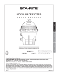
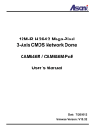
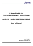
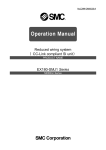
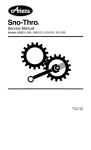
Workstation 2000
User’s Manual
Workstation 2000 User Manual
Table of Contents
What is a Workstation?…………………………………..
1
How Does It Work?…………………………………………. 2
Receiving And Inspection………………………………….. 3
Installation Guidelines……………………………………… 3
Disclaimer………...…………………………………………. 3
Electrical Assembly..………………………………………..
4
Compressed Air Supply………………………………….…. 4
Collector Power Switches………...………………………… 4
Quick Reference Manual—Wiring Diagram……………… 5
Collector Shutdown Procedure…………………………….. 6
Blower Assembly...………………………………………….. 6
Maintenance…………………………………………………. 6
MCS Controller Diagram………………………………….... 6
MCS Controller Setup...……………………………………. 7
Replacing Filters…………………………………………….
8
Replacement Parts………………………………………….. 9
Workstation 2000
The workstation is a completely self-contained unit consisting of a collector housing,
motor/blower system, filter cartridges and an on-line automatic pulse filter cleaning system. The “dirty air” inlet and “clean air” outlet shall be at the top. Large, easy opening
door provide access to filter cartridges and pulsing air reservoir areas for filter changes
and maintenance.
Cartridge Filter
access door
Outlet Panel
OR
After Filter Module containing
HEPA or Gas type filters.
Electronic Controls
• STOP/START switch
• Power Disconnect switch
• Pressure Gauge
• MCS Control Reading
Display Window
Access Door
• Reservoir
or
• Immersion Tank
14Ga Welded
Steel Construction
Filter Booth Assembly
• Metal Mesh Filters
Page 1
True DownFlow Technology
BLINDING / REENTRAINMENT:
Blinding occurs when dust reentrainment is advanced to the point where air flow through a filter is in sufficient for the task. Staggered blinding is where filters in a group are unevenly
loaded with dust.
INLET and DOWNFLOW
Inlet velocity should not exceed design conditions. (This requires some duct design planning
since velocity reduction requires distance of travel to reduce.) Otherwise dust storms and velocity spikes will destroy materials and cause unrestrained reentrainment.
DownFlow defines that gages will be introduced above the filters to purpose that fan energy,
gravity and cleaning energy will work together in the same direction, I.e., down towards the
hopper. Cleaning moves particles outward into a downward moving gas flow. Thus any rising
flow is compromising to favor reentrainment.
FILTERS: VERTICAL vs. HORIZONTAL
There is zero (cleaning reentrainment if each particle removed from a filter goes to the hopper
and not back on a filter. To this end, filters should be mounted vertically positioned in down
flowing dirty air. From a design point, it is the best.
Consider the lower cost design filters essentially mounted horizontal. First the top third of each
filter is a 2” deep dust trap. Secondly, dust cleaned from upper filters falls down into lower filters. This is reentrainment due to design. These flaws are not a part of the DownFlow design.
DIRECT TO THE HOPPER
Dust, as it passed the inlet deflectors, has an aerial view of the
filters and it sees only the top of filters and the open space between...direct to the hopper. In the DownFlow design, these two
areas are typically equal. Given Laminar flow, the gas velocity (at
A/C = 1.5:1) entering the open space between the filters is 412
fpm (Another example: if A/C = 2:1, the gas velocity downward
entering the open space between the filters is 549 fpm) This velocity regardless of A/C becomes 0 fpm at the base of each 52”
filter stack. Thinking of a dust particle entering the space between filters, it’s velocity vector is 412 units long and is directed to
the hopper. According to its mass, the particle is propelled per
MV2 towards the hopper. This is a negative system so the air
surrounding the particle is being attracted to the filter at a velocity
shown by a vector 1.5 units long. This is a correct representation and it illustrates the great
advantage of vertically positioned filters; i.e. in this true down flow design, dust particles by design are more compelled to bypass a filter than to enter it.
FILTERS
DownFlow filters are of excellent construction, matching the best available. We precondition
these filters with a unique process which has proven worthy over time. The cellulose media is
able to withstand water immersion and recover, which speaks to its high resin content (22% by
weight) and mechanical resilience.
Other: pleat lock construction, standard operating temperature of 220o F; short time exposure
to 300o F; Mullen burst 25 psig.
Page 2
Receiving and Inspection
Congratulations on the purchase of your new Clean Air America Workstation 2000
Upon receipt of the Workstation, remove the master packing list from the workstation
and reconcile it with the total shipment. Report any discrepancies to Clean Air America,
Inc. as soon as possible. Next remove the packaging from the unit then, if applicable,
remove the unit from the pallet. At this point, carefully inspect the workstation and any
other items shipped with the unit for any damage that may have been incurred during
shipping. If damage is found, report it to the shipping company immediately.
Installation Guidelines
Prior to using your Workstation, the unit must be fully assembled. Adequate electrical
and compressed air must also be connected to the workstation. These connections are
defined on page 4 of this manual.
Installation Instructions for WorkStation 2000
1.
2.
3.
4.
Determine desired location for Workstation 2000.
Anchor Booth to ground.
Apply silicone to Booth where Cabinet will mate.
Lift Cabinet using the four designated lifting points (one at each corner of the Cabinet).
5. Place the Cabinet onto the Booth with Cabinet Front (side with doors) facing the
same direction as the Booth Front (side with walk in opening). Use the bolt
pattern for alignment.
6. Bolt the Cabinet and Booth together securely.
Disclaimer
The Workstation is not designed to work with combustible materials, explosive
materials or particles. Operating the workstation with these materials could result in a serious fire inside the unit.
Page 3
Electrical Connections
Workstations operate on 208/460 volt, 3 phase power. The unit can also be configured
for 575 volt operation where necessary. Power is connected to the workstation at the
power junction box located on the right side of the unit. When power is properly
connected, the blower will rotate counter-clockwise when viewed from top of the workstation. To ensure proper operation, power connections should be performed by a certified Clean Air America, Inc installer or professional electrician. Any damage incurred
from improper electrical power connection will void the warranty of the workstation. A
wiring schematic is provided on page 5 of this manual.
DFC Workstation Power Switches
Power Disconnect Switch
This switch controls the main power to the workstation. When the switch is in the “0” position, main
power to the unit is disconnected. When in the “1”
position, main power is reaching the unit and it can
be started. To determine if power is reaching the
collector, with the switch in the “1” position, look into
the MCS controller window and see if the controller
display is active. If the display is active, power is
reaching the unit. This switch also provides the
means to lock out the switch using a small padlock
thus preventing accidental power up.
Power Start/Stop Switch
This switch controls the actual operation of the unit.
•
•
•
The “START” button begins the collectors operation
The “STOP” button stops the collectors operation
The “ON” light will illuminate when the “Start”
button is depressed. The light will remain
illuminated until the “Stop” button is depressed.
Compressed Air Connection
In order for the automatic pulse filter cleaning system to operate, Workstations require a
70 to 110 PSI dry, compressed air connection made to the unit. The compressed air inlet
is accessed by opening the top filter rank panel in the booth. The inlet is located inside
the opening, on the right side This inlet requires a 1-1/4” NPT male fitting. NOTE: Do
not operate the workstation without an appropriate compressed air supply. Doing
so will greatly diminish the life of the filter cartridges.
Page 4
Page 5
Collector Shutdown Procedure
Proper workstation shutdown is one of the key factors to achieving maximum filter
cartridge life. To properly shutdown the workstation, simply depress the “Stop” button. After approximately 1 minute, the workstation will cycle through its offline cleaning process.
Depending on model, this process could take up to 5 minutes. Always wait for the offline
cleaning process to finish before disengaging the Power Disconnect switch. NOTE:
Never shutdown the workstation by disengaging the Power Disconnect. If the
workstation is shut down in this manner, it WILL NOT perform offline cleaning and
diminish the life of the filter cartridges.
Blower Assembly
The Workstation is equipped with an impeller-style blower directly coupled to a high
efficiency TEFC motor. Some Workstation designs employ a housed blower assembly.
To ensure optimal workstation performance, this assembly is custom engineered by
Clean Air America for each customers particular application.
Maintenance
Workstations should be inspected and cleaned periodically. The inspection and cleaning interval depends on the amount of particulate generated in your specific application.
The units hopper, dust bin or dust tray should be emptied periodically and the waste disposed of in accordance with local regulations. Filter cartridges need replaced when the
set pressure drop indication is above the set “Delta-P” number. See page 10 for
instructions on filter cartridge replacement.
MCS Digital Controller
Face plate of the MCS controller is similar to drawing shown below.
(See Page 7—”MCS Controller Setup” for additional information)
Red indicates factory preset values
*1.7
*2.0
5
Page 6
MCS Controller Setup
The MCS Controller is configured at the factory during the test/inspection process. When the motor is not running, the controller display should read approximately zero (0) . When the motor is
started, it will increase to a level around 0.5 ÄP.
The following instructions will guide through any adjustments or changes that may need to be
made:
• Select the MANUAL or AUTOMATIC mode by moving the switch in the desired position (by
switching MANUAL Mode, the LED Manual will light up, and by switching to AUTOMATIC
Mode the LED AUTOMATIC will illuminate). In MANUAL Mode the unit will command the
valves with the Pause Time and Pulse Time which has been set. In AUTOMATIC Mode the
unit automatically regulates the Pause Time in order to maintain a constant Delta-P (ÄP).
When you select the PRECOATING function, you inhibit the MANUAL Mode.
1. Press SELECT MENU: on the display will flash the no. 1: with “+” or “-” select the PULSE
TIME
2. Press SELECT MENU: on the display will flash the no. 2: with “+” or “-” select the MANUAL
CYCLE TIME. Setting this function to select after how many seconds the “Economist’ returns
to command the same value. The “Economist” will automatically circulate the Pause Time
depending on the Manual cycle Time and the number of the connected valves.
3. Press SELECT MENU: on the display will flash the no. 3: with “+” or “-” select the SET
DELTA-P desired
4. Press SELECT MENU: on the display will flash the no. 4: with “+” or “-” select the DELTA-P
value that will activate the ALARM.
5. Press SELECT MENU: on the display will flash the no. 5: with “+” or “-” select the NO. OF
CYCLES FOR THE “SHUT DOWN CLEANING” which is automatically inserted when the
Delta-P goes below 0.1kPa, once the fan has been switched off. By selecting 0 you will
bypass the Shut Down Cleaning. During the Shut Down Cleaning cycle the letter E will
appear on the display. Upon termination of the end cycle cleaning will appear on the display
“END” to indicate that the cleaning cycle has ceased. (Note: no connection required as it
functions with Delta-P).
6. Press SELECT MENU: on the display will flash the no. 6: with “+” or “-” select the DELTAPRECOATING value desired (by selecting 0 you will bypass this function). The “Economist”
will only accept a Delta-P greater than the set Delta-P (see step 3). The valve will not pulse
until the Delta-P PRECOATING value has been reached, regardless of the Set Delta-P (step
3) or the Delta-P Alarm (step 4). It will also ignore the Shut Down Cleaning function if the set
Delta-P PRECOATING value has not been reached. Once the Delta-P PRECOATING value
is reached, the cycle of the valves will start and the PRECOATING function will autodelete,
until you’ll assign it a new value.
7. Press SELECT MENU: on the display will flash the no. 7HH: immediately appears on the
display the HOUR COUNTER with 4 digits. When the counter arrives to 9999, the Hour
Counter will recommence at 0.
8. Press SELECT MENU: on the display will flash 8PAS: key access to the SUBMENU (only if
necessary request the instruction page): press SELECT MENU again; on the display will
appear the letter E: The cycle starts
NOTES:
• Pressing the key “Delta-P/valves” it is possible to return in E (run) from every step of the
programming
• During the programming, after 2 minutes from the last setting, the unit automatically returns to
E (run)
• The system will automatically ignore the outlets which have not been connected (lead search),
displaying rapidly the outlets which have not been detected
• During the first cycle, check that all of the outlets function correctly (in the case that they are
ignored check the connections to the solenoid, or check that there is power from the solenoid).
Page 7
Replacing Filters
Proper filter cartridge replacement is important to optimal performance of the Workstation. Replacement filter cartridges are available from your Clean Air America sales
representative. When changing filter cartridges, use the process outlined below.
1. Press the STOP switch and allow blower to spin down so that system can perform a Shut
Down Cleaning Cycle.
2. Move Auto / Manual Switch to Manual
At this point, the valves will pulse alternately approximately every 15 seconds. If unit does
NOT pulse every 15 seconds, press Select Menu. Display will flash No:1
Set to 0.2 with “+”
or “-” key (for Pulse Time) Press Select Menu again. Display will now flash No:2
Set to 12
with “+” or “-” key (for seconds between pulses). Note: Pressing Key “Delta-P/valves” allows
you to return to E (run) from every step of the programming menu. Let valves pulse with a
pause time between pulses of at least 15 seconds to clean filter cartridges a much as
possible.
3. Reset Auto / Manual Switch to Auto
4. Start workstation and allow it to run for 1 minute.
5. Spin down Blower. Note: The Blower must stop completely before opening the Filter Door
(Step 8)
6. Switch off MCS Controller by placing the power switch (bottom left of controller) in the “0” position This will prevent the unit from doing another Shut Down Cleaning Cycle.
Replacing Cartridge Filters
1. OPEN Filter Door
2. To loosen the filter lid, turn T-Handles located at the top of the filter cartridges (counterclockwise when viewing from top)
3. Remove filter lids
4. Slide out Tray with T-Handles and clean thoroughly.
5. Slide large plastic bag over the top of 1 filter cartridge and move bag all the way down to bottom of filter cartridge.
6. Remove Filter Cartridge and tie bag closed.
7. Repeat steps 11 and 12 until all filter cartridges to be replaced have been removed.
8. Install new filters being sure to face the end with the rubber seal downward. Make sure filter
lid is centered on filter.
9. Slide in Tray with T-Handles. Make sure indentation in T-Handle is centered on raised part of
filter lid.
10. Tighten T-Handles by turning clockwise (when viewing from top) so that filter lids are secured.
11. Close and secure Filter Door
12. Press Start Switch and allow Blower to spin up
13. Switch on MCS Controller by placing the Power Switch in the “1” position.
Replacing Metal Mesh Filters
1.
2.
3.
4.
5.
6.
7.
8.
9.
Remove 2 bolts from upper filter rack access door.
Gently lower access door until you can easily reach the metal filters
Slide out filters
Wash / clean filters
When thoroughly dry replace the filters back into the rack
Raise the access door back into closed position and reinstall bolts
Repeat steps 1 to 6 for the lower filter rack access door
Press Start Switch and allow Blower to spin up
Switch on MCS Controller by placing the Power Switch in the “1” position
Page 8
Workstation 2000 Replacement Parts
CAA Part #
Item Description
1834 (Cellulose) or 2468 (Polyester)
Cartridge Filter 26”
2790
Metal Mesh Filters 24” x 24”
1862 (5 and 10Hp) ; 3069 (15Hp)
Motor Starter
1902
ON/ OFF Switch
2642
MCS Controller
6391
Pressure Gauge
1884
Disconnect Switch
6346
Motor / Blower 5 Hp
2475
Motor / Blower 10 Hp
2476
Motor / Blower 15 Hp
3041
Immersion Tank
Page 9