1
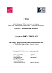
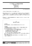
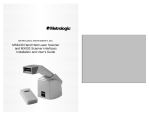
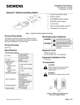
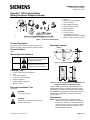
Installation Instructions
Document No. 129-404
January 21, 2013
OpenAir™ GCA Spring Return
Rotary Electronic Damper Actuator
a.
b.
c.
d.
e.
f.
g.
h.
i.
b
d
i
a
g
e
h
Manual
Override
f
EA0878R3
c
j
j.
Actuator
Self-centering shaft adapter
Position indicator
Shaft adapter locking clip
Position indicator adapter
Mounting bracket
Mounting screws
3 mm hex wrench
Conduit adapter 1/2-inch
(Not available to GCAxxx.xP models)
500 ohm resistor (GCA15x.xx only)
Figure 1. Parts of the GCA Actuator.
Product Description
Describes the steps for direct-coupled mounting of the
OpenAir GCA spring return electronic damper actuators.
Mounting Positions
NEMA 2
Product Numbers
GCAx
WARNING:
Personal injury or loss of life
may occur if you do not follow a
procedure as specified.
CAUTION:
Equipment damage or loss of
data may occur if you do not
follow a procedure as specified.
EA1104R1
Warning/Caution Notations
<9
0˚
< 90
90
˚
˚
Figure 2. Acceptable NEMA 2-Positions.
•
•
•
•
•
•
•
10 mm (13/32-inch) open-end wrench
Drill
4 mm (5/32-in) drill bit
3 mm hex wrench (provided)
Phillips screwdriver
Small flat-blade screwdriver
Marker or pencil
Expected Installation Time
30 minutes
WARNING:
Do not open actuator.
EA1105R1
Required Tools
90˚
Figure 3. Only Acceptable Position for NEMA Type 3R
Rating Using ASK75.1U Weather Shield.
The GCA actuator is UL listed to meet NEMA Type 3R
requirements (a degree of protection against rain, sleet,
and damage from external ice formation) when installed
with the Weather Shield (product number ASK75.1U) and
outdoor-rated conduit fittings. Actuator must be in the
vertical position.
Prerequisites
CAUTION:
Do not turn the 3 mm hex key against the
direction of the arrow.
Item Number: 129-404 Rev. JA
NOTE: Actuator is shipped from the factory with 5°
preload. When power is applied to the actuator,
the preload is released. To manually release the
preload, insert the 3 mm hex key in the override
opening and turn the key in the direction of the
arrow. See Manual Override.
Page 1 of 7
Document No. 129-404
Installation Instructions
January 21, 2013
Installation
Table 1. Actuator Positioning and Damper Control.
1
Determining the Actuator
Mounting Orientation
Damper
Type
Power Fail
Spring Return
Position
EA1055R1
Close
Close
Open
Open
3
90
90
Actuator
Mounting
Orientation
2-Position
EA1038R1
2
Manual
Override
Manual
Override
90
90
Manual
Override
Manual
Override
GCA12x
Power On
Open
Close
Open
Close
Open
Close
Open
Close
GCA22x
3-Position
Y1
Y2
GCA13x
Y1
Page 2 of 7
Open
Close
Open
Y2
Modulating Control
EA1040R1
EA1039R1
Close
Y = 10V
GCA15x
Y = 2V
GCA16x
GCA15x
Close
Open
Close
Y = 2V
Y = 10V
GCA16x
Open
Y = 10V
(or Y = Uo + ΔU)
Close
Open
Close
Open
Y = 0V
(or Y = Uo)
Siemens Industry, Inc.
Document No. 129-404
Installation Instructions
January 21, 2013
d
c
3
> 77 mm
>3 in
4
2
b
MANUAL
OVERRIDE
a
NOTE:
MANUAL
OVERRIDE
3
1
2
SHAFT
ADAPTER
ALIGNMENT
MARK
d
Place the shaft
adapter right next
to the alignment
mark, keeping
the mark visible.
90
b
4
>20 mm
<77 mm
>3/4 in
<3 in
e
a
c
5
EA1022R1
MANUAL
OVERRIDE
MANUAL
OVERRIDE
Figure 4. Shaft Length and Proper Shaft Adapter Location.
OR
NOTE: If the damper
fail-safe position is
open, change the
actuator preload from
the factory-set 5° to
85°. See Manual
Override.
4
4
3
3
MANUAL
OVERRIDE
EA0289R2
MANUAL
OVERRIDE
Figure 6. Place the Actuator on the Shaft.
Figure 5. Close the Damper.
7
1/2
7
1/2
5
4 mm
5/32 in.
2 PLACES
f
EA0357R2
10 mm
13/32 in.
10 mm
13/32 in.
g
Apply 7.5 lb-ft
(10 Nm) torque
maximum
EA0359R3
6
MANUAL
OVERRIDE
MANUAL
OVERRIDE
Figure 7. Fasten the Mounting Bracket.
Figure 8. Fasten the Shaft Adapter to the Damper Shaft.
Siemens Industry, Inc.
Page 3 of 7
Document No. 129-404
Installation Instructions
January 21, 2013
Mechanical Range Adjustment
Manual Override
1
90˚
5
2
3
90˚
2
al
Manu
ide
Overr
HOLD
1
al
Manu
ide
Overr
TRAIN
GEAR PIN
LOCK
al
Manu
ide
Overr
5
TRAIN
GEAR PIN
LOCK
h
EA0374R3
3 mm
6 7 8
4
TRAIN
GEAR PIN
LOCK
4
Figure 9. Manual Override.
To use manual override or set preload, do the
following: (Figure 9)
MANUAL
OVERRIDE
EA0279R1
3
x 7-3/4 = 90˚
EA0278R2
90˚
MANUAL
OVERRIDE
Figure 10. The Angular Rotation is Adjustable Between 0°
and 90° at 5 Degree Intervals.
Make sure the actuator is in the "0" (fail-safe) position when making
this adjustment. If making the adjustment before the actuator is in
service, take into account the factory set 5° preload. To release the
preload, see To Release Manual Override or Preload section.
Other settings
1.
Insert the 3 mm hex key in the override opening,
(Step 1).
For adjustment of auxiliary switches and span/offset options see the
Technical Instructions listed under References.
2.
Turn the key in the direction of the arrow until you
reach the desired degree of opening, (Step 2).
Tandem Operation
3.
Hold the key in place, (Step 3).
Two GCA Actuators with 2-position or floating control signal are
mounted to the same side of the damper shaft using the ASK73.1
Tandem Mounting Bracket as shown in Figure 11.
4.
Insert a small flat-blade screwdriver into the gear
train lock pin. Turn the screwdriver in the same
direction as the arrow until you hear a click or meet
slight resistance, (Step 4).
Two GCA Actuators with a modulating control signal are mounted to
the same side of the damper shaft using the ASK73.2U Tandem
Mounting Bracket also as shown in Figure 11.
CAUTION:
When engaging the gear train lock pin,
cautiously turn only about 5 degrees
until you hear a click or meet slight
resistance. Turning too far will strip the
lock pin.
5.
Remove the key or keep it in place, (Step 5).
1.
Insert the 3 mm hex key in the override opening,
(Step 6).
2.
Turn the key only a short distance in the direction of
the arrow, (Step 7).
3.
Remove the key, (Step 8).
The actuator will return to "0" (fail-safe) position.
NOTE: Applying power and sending a control
signal will release manual override.
Page 4 of 7
EA0905R1
To release manual override or preload
Figure 11. Tandem Mounting on Same Side of Damper Shaft.
NOTE: For applications requiring single damper shaft operation by
up to four GCA modulating control signal actuators mounted
on each side of the damper shaft, use the GCA15x Series
Actuators with Master/Slave mode operation selected. See
Figure 12.
(See Wiring Diagrams for GCA15x Series master/slave operation
wiring instructions.) (See OpenAir™ Spring Return Electric Damper
Actuator Modulating Control Technical Instructions document
155-173P25 for complete tandem mounting instructions.)
Siemens Industry, Inc.
Document No. 129-404
Installation Instructions
January 21, 2013
Wiring Diagrams
Modulating 0 to 10 Vdc Control, 24 Vac: GCA16x
Modulating 2 to 10 Vdc Control, 24 Vac/dc: GCA15x
8
9
S1
S4
SH
EA0284R1
PU
A
B
S2 S3
S5 S6
M
2
1
EA0909R1
2-position Control, 24 Vac/dc: GCA12x
1
Figure 12. Tandem Mounting on Each End
of Damper Shaft.
EA0281R1
S1
References
OpenAir™ Spring Return Electric Damper Actuator Modulating
Control Technical Instructions (155-173P25).
OpenAir™ Weather Shield Kits Installation Instructions
(129-261).
Use earth ground isolating step-down Class 2
transformers. Do not use autotransformers.
NOTE:
The maximum rating for a Class 2 step-down
transformer is 100 VA. Determine the supply
transformer rating by summing the VA ratings
of all actuators and all other components
used. It is recommended that not more than
80% of the transformer VA be utilized. The
GCA actuator consumes 8 VA or less.
P3
S1
S4
A
B
S2 S3
S5 S6
2-position Control, 120 Vac: GCA22x
LINE
3
DUAL AUXILIARY
SWITCHES
COMMON COMMON
S1
S4
SWITCH
A
SWITCH
B
EA0863R1
M
4 GND
NEUTRAL
S2
S3
S5
N.C. N.O.
S6
N.C. N.O.
Special Application: Modulating 4 to 20 mA
Control with GCA15x and external 500 ohm
resistor
8
Actuator
Siemens Industry, Inc.
P2
2
1
Either AC line voltage from the same phase
must be applied to all six outputs of the dual
auxiliary switches, or UL-Class 2 voltage
must be applied to all six outputs.
2
S1
S4
500
A
B
S2 S3
S5 S6
M
EA1102R1
Operating
Power
Voltage
Consumption
Modulating Control
GCA16x
24 Vac
7 VA/5W
GCA15x
24 Vac/dc
7 VA/5W
2-Position and Floating Control
GCA12x,
24 Vac/dc
7 VA/5W
GCA13x
GCA22x
120 Vac
8 VA
S5 S6
0%
100%
1000
M
CAUTION:
Mixed switch operation to the switching
outputs of both auxiliary switches (A and B)
is not permitted.
NOTE: With Plenum cables, only UL-Class
2 voltage is permitted.
S2 S3
7
P1
EA1103R1
•
B
Floating Control, 24 Vac/dc: GCA13x
6
All wiring must conform to NEC and local codes and
regulations.
A
M
2
Wiring
•
S4
9
1
Page 5 of 7
Document No. 129-404
Installation Instructions
January 21, 2013
Table 2. Wire Designations.
Wiring Diagrams, Continued
Standard
Symbol
Master/Slave: GCA15x
1
2
3
4
6
Supply (+)
Controller
Control Signal
0 to 10 Vdc
1
Supply
Input 0 to 10 Vdc
or 2 to 10 Vdc
Neutral
Actuator 1
G
G0
L
N
Y1
Red
Black
Black
White
Violet
Red
Black
Black
White
Violet
Y2
Orange
Orange
Y
Gray
Gray
U
Pink
Pink
S1
Q11
S2
Switch A N.C.
Q12
S3
Switch A N.O.
Q14
S4
Switch B Common
Q21
S5
Switch B N.C.
Q22
S6
Switch B N.O.
Q24
P1
Feedback
Potentiometer
0 to 100% P1 - P2
Feedback
Potentiometer
Common
Feedback
Potentiometer
100 to 0% P3 - P2
a
Gray/
red
Gray/
blue
Gray/
pink
Black/
red
Black/
blue
Black/
pink
White/
red
Gray/
red
Gray/
blue
Gray/
pink
Black/
red
Black/
blue
Black/
pink
Black
b
White/
blue
Black
c
White/
pink
Black
7
8
2
Output (Feedback)
9
9
8
1
Supply
Input 0 to 10 Vdc
or 2 to 10 Vdc
Neutral
Actuator 2
2
8
1
Input 0 to 10 Vdc
or 2 to 10 Vdc
Supply
Neutral
EA1217R1
Actuator 3
2
Neutral (-)
Color
Standard Plenum
Supply (SP)
Neutral (SN)
Line
Neutral
Control signal
clockwise
Control signal
counterclockwise
(GCA16x)
Input Signal
0 to 10 Vdc (GCA16x)
2 to 10 Vdc (GCA15x)
Position Output
0 to 10 Vdc (GCA16x)
2 to 10 Vdc (GCA15x)
Switch A Common
Neutral
8
Terminal
Connection
Function
P2
P3
Retrofit Wiring
Modulating Control
(0 to 10 Vdc)
Function
Supply (24V)
Common
0(2) to 10 Vdc Input
0(2) to 10 Vdc Feedback
2-Position Control
(24 Vac/Vdc)
Function
Supply (24V)
Common
2-Position Control
(120 Vac)
Function
Line (120V)
Neutral
Page 6 of 7
Siemens
GCA Series
Color
Red
Black
Gray
Pink
Number
Color
Number
1
2
8
9
Red
Black
White
Orange
2
1
3
5
Siemens
GCA Series
Color
Red
Black
Number
1
2
Siemens
GCA Series
Color
Black
White
Belimo
AFB Series
Number
3
4
Belimo
AFB Series
Color
Red
Black
Number
2
1
Belimo
AFB Series
Color
Black
White
Number
2
1
Honeywell
MS7520 Series
Color
Red
Black
White
Blue
Number
Color
Number
1
2
3
5
Red
Black
Gray
Orange
2
1
3
4
Honeywell
MS8120 Series
Color
Red
Black
Number
1
2
Honeywell
MS4120 Series
Terminal
Only
Johnson
M9220 Series
Number
1
2
Johnson
M9220 Series
Color
Red
Black
Number
2
1
Johnson
M9220 Series
Color
Black
White
Number
2
1
Siemens Industry, Inc.
Document No. 129-404
Installation Instructions
January 21, 2013
Dimensions
4-3/16
(106)
OPENING FOR
STANDARD 1/2"
CONDUIT
CONNECTOR (2)
∅
1.04
(26.5)
EA0846R1
8-1/4
(210)
15-3/8
(390)
4-1/16
(103)
1-3/8
(35)
Figure 13. Dimensions of the ASK75.1U Weather Shield in Inches (Millimeters).
min. 4 in.
100 mm
3-1/16 in.
78 mm
MAX
3/4 in.
20 mm
1-1/8 in.
28 mm
11-13/16 in.
300 mm
3-3/8 in.
86 mm
min. 8 in.
min. 1/4 in.
7 mm
200 mm
7-3/4 in.
197 mm
1 in.
25 mm
5/32 in.
4 mm
1-11/32
1-11/32
34 mm
34 mm
3-15/16 in.
min. 2-1/2 in.
60 mm
100 mm
EA1087R1
OPENING
FOR 3/8"
FLEX CONDUIT
(3 PLS)
11/32 in.
10 mm
1-23/32 in.
30 mm
1.1 in.
28.5 mm
Figure 14. Dimensions of the GCA OpenAir Actuator and Mounting Bracket in Inches (Millimeters).
Information in this publication is based on current specifications. The company reserves the right to make changes in specifications and
models as design improvements are introduced. OpenAir is a trademark of Siemens Scheiwz AG. Other product or company names
mentioned herein may be the trademarks of their respective owners. © 2013 Siemens Industry, Inc.
Siemens Industry, Inc.
Building Technologies Division
1000 Deerfield Parkway
Buffalo Grove, IL 60089-4513
USA
+1-847-215-1000
Your feedback is important to us. If you have comments
about this document, please send them to
[email protected]
Document No. 129-404
Printed in the USA
Page 7 of 7