1
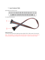
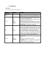
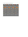
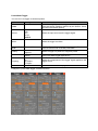
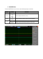
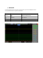
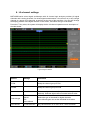
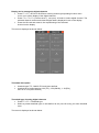
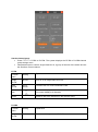
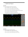
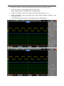
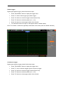
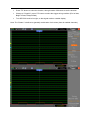
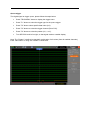
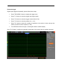
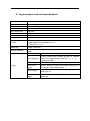
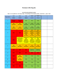
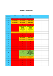
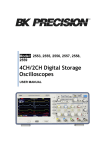
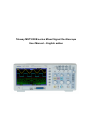
Tekway MST1000B series Mixed Signal Oscilloscope
User Manual – English addon
1. Logic Analyzer Cable
MST1000B Logic Analyzer pinout
Port cable as shown below:
Digital signal input
In order from left to right for the digital signal input (GND, D0-D15, GND) a total of 18 input ports.
Note::Pins marked as “N” in picture above are NOT free/not connected, for sure they do have a
function (threshold voltage and maybe VCC for active probe – I need to check this in detail)
2. Trigger Menu
Edge trigger
You can use it to trigger on waveform edges
Options
Trigger Type
Settings
Edge
Source
CH1
CH2
EXT
EXT/5
AC Line
D0-D15
Mode
Auto
Normal
Coupling
AC
DC
HF Reject
LF Reject
Comments
By default the oscilloscope uses the edge trigger which
triggers the oscilloscope on the rising or falling edge of the
input signal when it crosses the trigger level (threshold).
Select the input source as the trigger signal.
CH1, CH2: No matter the waveform is displayed or not, a
certain channel will be triggered.
EXT: Does not display the trigger signal and allows a
trigger level range of +1.6V to -1.6V.
EXT/5: Same as EXT option, but attenuates the signal by
a factor of 5 and allows a trigger level range of +8V to -8V.
AC Line: Uses a signal derived from the power cord as the
trigger source.
D0-D15: trigger on LA falling or rising edge.
Select a trigger mode.
By default, the oscilloscope uses the Auto mode. In this
mode, the oscilloscope is forced to trigger when it does
not detect a trigger within a certain amount of time based
on the SEC/DIV setting. The oscilloscope goes into the
scan mode at 80ms/div or slower time base settings.
In the Normal mode, the oscilloscope updates the display
only when it detects a valid trigger condition. New
waveforms are not displayed until they replace old ones.
Use this mode to just view valid triggered waveforms.
Only after the first trigger does the display appear.
Select the components of the trigger signal applied to the
trigger circuitry.
AC: Blocks DC components and attenuates signals below
10Hz.
DC: Passes all components of the signal.
HF Reject: Attenuates the high-frequency components
above 80kHz.
LF Reject: Blocks DC components and attenuates the
low-frequency components below 8kHz.
Example of “edge trigger” selected sources:
Pulse Width Trigger
You can use it to trigger on aberrant pulses.
Options
Settings
Pulse
Source
When
Set
Width
Pulse
Polarity
Mode
Coupling
More
CH1
CH2
EXT
EXT/5
D0-D15
=
≠
<
>
20ns to 10.0sec
Positive
Negative
Auto
Normal
AC
DC
HF Reject
LF Reject
Comments
With Pulse highlighted, the trigger occurs on pulses that
meet the trigger condition (defined by the Source, When
and Set Pulse Width options).
Select the input source as the trigger signal.
Select the trigger condition.
With Set Pulse Width highlighted by pressing F4, turn the
multi-functional knob to set the pulse width.
Select to trigger on positive or negative pulses.
Select the type of trigger. The Normal mode is best for
most pulse width trigger applications.
Select the components of the trigger signal applied to the
trigger circuit.
Switch between submenu pages.
Example of “pulse width trigger” selected sources:
3. SAVE/RECALL
Press the SAVE/RECALL button to save or recall oscilloscope setups or waveforms.
Options
Settings
Comments
Waveforms
Source
CH1
CH2
MATH
LA
Select a displayed waveform to store.
REF
RefA
RefB
Select the reference location to store or recall a waveform.
Save
Save the source waveform to the selected reference location.
Operation
Ref on
Ref off
Display or remove the reference waveform on the screen.
Options
Settings
Comments
CSV
Source
Operation
CH1
CH2
LA
Select a waveform be to stored.
LA as source not yet implemented but announced in chinese
manual.
Save
Save waveform data to flash drive.
Recall
Load waveform from flash drive and displayed on the screen.
Delete
Remove waveform data from flash drive.
4. MEASURE
For DSO operations there are 23 types of measurements, up to 8 can be displayed at a time.
For LA operations there are 2 types of measurments.
Options
Source
Measurement
Type
Settings
CH1
CH2
LA
Comments
Frequency
CH1, CH2, LA.
Period
Any other measurement type
Off
CH1, CH2, LA
CH1, CH2 only
CH1, CH2, LA.
Select the measure source.
5. CURSOR
Push the CURSOR button to display the Cursor Menu.
Options
Settings
Type
Off
Voltage
Time
Track
Source
CH1
CH2
MATH
REFA
REFB
LA
Select Cursor
S
E
Delta
Display the
difference
(delta)
between the
cursors.
Comments
Select a measurement cursor and display it.
Voltage measures amplitude while Time measures time and
frequency. Track is displaying both, but the data is only valid while
in run mode.
In LA mode only “Time” cursor is available.
Select a waveform to take the cursor measurement.
Use the readouts to show the measurement.
S indicates Cursor 1. E indicates Cursor 2.
A selected cursor is highlighted, which can be moved freely. Both
cursors can be selected and moved at the same time. The box
behind the cursor displays the location of the cursor.
Display the measurement in the box under this option.
6. LA channel settings
MST1000B series mixed signal oscilloscope with 16 channel logic analyzer provides 16 logical
channels and 2 analog channels, for mixed-signal measurements. You can turn on (or off) a single
channel or a group of (8) channels, as well as set the size of the waveform. You can also change
the display position of the digital channel on the screen, and select the type of threshold.
Press the F7 key twice, the system will display the the LA channel operation menu description of
the table below.
Logic analyzer interface
Options
Settings
Comments
D7-D0
Setup the channel group D7-D0
D15-D8
Setup the channel group D15-D8
Current channel
<D15-D0>
Select a digital channel (for position change and/or
treshold). Selected digital channel marked with red color.
Treshold type
TTL
CMOS
ECL
User-defined
Select the type of threshold for digital channels,
user-defined types can set the threshold level values
User-defined
<Treshold level>
Any value between -8.0V and +8.0V, 10mV resolution
Display and re-arrange the digital channels
• Press F7-> F7-> D7-D0 or D15-D8 to entering channel group setting function menu
to turn on or off the display of the digital channels.
• Press F7-> F7-> F3 (“Current chan.”), use (turn) V0 knob to select digital channel. The
selected channel number and channel digital data is displayed in red on the display.
• Press the V0 knob and rotate it, the re-positioning of the selected
channel on the display.
The menu is displayed as shown below.
Threshold description:
• threshold type TTL, CMOS, ECL and Users defined
• threshold level varies between 2.6V(TTL), 2.5V(CMOS), -1.3V(ECL),
and -8V to +8 V(User Defined)
Threshold type of setting digital channels
• Press F7-> F7-> Threshold type
• Select a preset threshold type or user-defined to set (use V0 knob) your own threshold
level.
The menu is displayed as shown below.
Set the channel group
• Press F7-> F7-> D7-D0 or D15-D8. The system displays the D7-D0 or D15-D8-channel
group settings menu
• Independent open or close a single channel or 8, a group of the size of the switch and set
the waveform control channel
D7-D0
Function
menu
Setting
Explanation
Single
On/Off
D7-D0
Turn on or off single channel D7-D0
Multi.
On/Off
All on
All offl
Forced to turn on or off 8 channels D7-D0
Waveform
size
Full screen displays 8 channels
Full screen displays 16 channels
Reset
Reset D7-D0 of the waveform in the channel group
D15-D8
Function
menu
Setting
Explanation
Single
On/Off
D15-D8
Turn on or off single channel D15-D8
Multi.
On/Off
All on
All offl
Forced to turn on or off 8 channels D15-D8
Waveform
size
Full screen displays 8 channels
Full screen displays 16 channels
Reset
Reset D15-D8 of the waveform in the channel group
Open and close a single digital channel:
•
Press F7-> F7-> D7-D0-> channel settings
•
Use multifunctional knob V0 and F1 button to open or close single digital channel
Forced to turn on or off all digital channels:
•
Press D7-D0-> D7-D0-> “All On” (or “All Off”),
or
•
Press D15-D8-> D15-D8-> “All On” (or “All Off”).
Additionaly you can turn on or off a single digital channel in the selected channel group.
To open or close a channel:
•
Use multifunctional knob V0 and F1 button to open or close single digital channel
Set digital channel waveform size:
•
Press D7-D0-> F3 (to change waveforms size),
or
•
Press D15-D8-> F3 (to change waveforms size).
The reset digital channel waveform display:
•
Press D7-D0-> Reset,
or
•
Press D15-D8-> Reset.
Additionaly you might use “Default Setup” (or manually remove /param/sav/r* on DSO file system)
to remove any other LA-related setting.
.
7. Digital signal triggers
Edge-trigger
Edge-triggered digital signal, please follow the steps below:
•
Press "TRIG MENU" button to display the trigger menu.
•
Press "F1" button to select the trigger type for edge-triggered.
•
Press "F2" button to select the desired trigger source (D0 to D15).
•
Press "F3" button to select the slope (rising edge triggered or falling edge trigger).
•
Press "F4" button to select trigger modes: Auto, Normal.
Note: coupling mode is only effective on the analog signal.
•
Turn SEC/DIV knob left or right, so that signal reaches a stable display.
Pulse trigger
Digital signal pulse trigger, please follow these steps:
•
Press "TRIG MENU" button to display the trigger menu.
•
Press "F1" button to select the trigger type for pulse triggering.
•
Press "F2" button to select the desired trigger source (D0 to D15).
•
Press "F3" button to select the pulse polarity (positive pulse or negative pulse).
•
Press "F4" button to select trigger modes: Auto, Normal.
Note: coupling mode is only effective on the analog signal.
•
Change to "Page2/2", press "F4" button to select the trigger timing (=, ≠,>, <).
•
Press "F5" button to select the trigger pulse width, through rotation V0 buttons to set
trigger pulse width.
•
Turn SEC/DIV knob left or right, so that signal reaches a stable display.
Pattern trigger
Digital signal pattern trigger, please follow these steps:
•
Press "TRIG MENU" button to display the trigger menu.
•
Press "F1" button select trigger type pattern trigger.
•
Press "F2" button to select the trigger channel (D0 to D15).
•
Press "F3" button to select the pattern (H, L, or X).
•
Press "F4" button to select trigger modes: Auto, Normal.
•
Turn SEC/DIV knob left or right, so that signal reaches a stable display.
Note: The “Pattern” is defined as (parallel) combination of all values (from all enabled channels).
Continuous trigger
Digital signal duration trigger, please follow these steps:
•
Press "TRIG MENU" button to display the trigger menu.
•
Press "F1" key to select the trigger type for continuous trigger.
•
Press "F2" button to select the trigger channel (D0 to D15).
•
Press "F3" button to select the pattern (H, L, or X).
•
Press "F4" button to select trigger modes: Auto, Normal.
•
Press "F5" button to select the duration, through rotation V0 buttons to set the duration.
•
Change to "Page2/2", press "F5" button to select the trigger timing condition (End of data,
Begin of Data, Delayed Data)
•
Turn SEC/DIV knob left or right, so that signal reaches a stable display.
Note: The “Pattern” is defined as (parallel) combination of all values (from all enabled channels).
Queue trigger
The digital signal to trigger queue, please follow the steps below:
•
Press "TRIG MENU" button to display the trigger menu.
•
Press "F1" button to select the trigger type for the queue trigger.
•
Press "F2" button select specific data index (0-3).
•
Press "F3" button to select the trigger channel (D0 to D15).
•
Press "F4" button to select the pattern (H, L, or X).
•
Turn SEC/DIV knob left or right, so that signal reaches a stable display.
Note: The “Pattern” is defined as (parallel) combination of all values (from all enabled channels).
Each “Data Index” is using own “Pattern” combination.
Repeated trigger
Digital signal triggered repeatedly, please follow these steps:
•
Press "TRIG MENU" button to display the trigger menu.
•
Press "F1" button to select the trigger type trigger repeat.
•
Press "F2" button to select the trigger channel (D0 to D15).
•
Press "F3" button to select the pattern (H, L, or X).
•
Press "F4" button to select the number of repetitions, the number of times through the
rotation V0 knob to set the repeat (0 - 255).
•
Turn SEC/DIV knob left or right, so that signal reaches a stable display.
Note: The “Pattern” is defined as (parallel) combination of all values (from all enabled channels).
8. Logic analyzer technical specifications
Number of channels
16
Input impedance
200K (C=10p)
Input voltage range
-60V to +60V
Treshold level
-8V to +8V
Max. sample rate
500 MS/s
Analog Bandwidth
100MHz
Input standards
TTL,CMOS,ECL,User defined
Depth per channel
4 to 512KSample (timebase and DSO memory depth dependant)
Cursors
Measuring
Memory capability
Trigger
Cursor between the voltage difference △V
Cursor between the time difference △T
△T Frequency(1/△T)
Period, Frequency
RefA
RefB
Edge-triggered
D0-D15 selected slope (rising or falling edge)
Pulse triggering
D0-D15 selected pulse polarity (positive or negative
pulse), Pulse trigger timing condition (=,≠,>,<),
Trigger pulse width
Pattern trigger
D0-D15 selected pattern (H,L,X)
Continuous
trigger
D0-D15 selected duration and trigger timing (end of
data, begin of data, delayed data)
Queue trigger
D0-D15 selected particular data index (0-3) and the
pattern (H,L,X)
Repeated
trigger
D0-D15 selected pattern (H,L,X) and the number of
repetitions