1
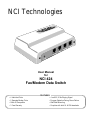
NCI Technologies
TE
M
M
DE
O
Q
LE
PT
S
X
FA
NE
L
LI
TE
12
C
VA
User Manual
for
NCI 424
Fax/Modem Data Switch
FEATURES
•
•
•
•
4 Individual Ports
2 Separate Modem Ports
Caller ID Compatible
3 Year Warranty
•
•
•
•
True 90V, 20 Hz Ringing Signal
Program Retention During Power Failure
Wall/Shelf Mounting.
Complies with both UL & CSA standards
I M P O R T A N T
N O T I C E
Should you require technical assistance during installation, please call our toll-free Technical Support Line
1-888-633-2666
SPECIFICATIONS
Power
Requirements:
120 VAC, 50-60 Hz
AC Adapter with an output of
12 VAC @ 1 A
Line Voltage
Tolerance:
120 VAC, ± 8%
Ringer
Equivalence
FCC REN: 0.7B
IC REN: 0.3
Ringer Signal
90VAC 20Hz
Facility
Interface:
RJ11X / CA11A
Modular Jack
7 5/16" x 4 5/8" x 2"
Dimensions:
185mm x 118mm x 50mm
Weight:
1.1 lb (500 g)
FCC Reg. No.
GUI3SE-60256-OT-N
DOC Certification:
973 3176 A
INSTALLATION
The diagrams shown below cater to the most common installations.
If you have only one (1) line, follow diagram A.
If you have two (2) or more lines, follow diagram B. It is important that the NCI 424 Fax/Modem Data Switch be connected
to the last line. This ensures that an incoming fax or modem transmission will be routed directly to the Fax/Modem Switch
and not to an unoccupied telephone line.
A - Installation in a Single Line Application
120 Volt AC
Power Adapter
12 VAC
TEL.LINE
FAX
MODEMS
DTMF telephone sets
1
2
3
4
5
6
7
8
9
*
0
#
Wiring Diagram for
Modems-1 and Modems-2
Application
Answering Machine
Recorder
(optional)
TEL.EQPT.
12 VAC
Note: All extension phones on the same line must be connected
to the TEL. EQPT. jack of the Fax/Modem DataSwitch
Standard 4 conductor
modular cable
(One included)
CA11
RJ11
CA11
RJ11
2
Yellow
3
Green
3
5
Black
4
Red
CA11
RJ11
4
MODEMS–1
Incoming line
from Telephone
Network (C.O.)
3
FAX
Modem 1
RJ11/CA11
Jack
Modem 2
CA11
RJ11
4
MODEMS–2
B - Installation in a Multi-Line Application
120 Volt AC
Power Adapter
Modem 1
12 VAC
TEL.LINE
FAX
MODEMS
Modem 2
For 2 Modem Application
see Wiring Diagram of
Installation A
TEL.EQPT.
12 VAC
FAX
RJ11/CA11
Jacks
Last Line
Incoming lines
from Telephone
Network (C.O.)
Line 2
Line 1
1
Key
System
Unit
(KSU)
2
3
1
2
3
1
2
3
4
5
6
4
5
6
4
5
6
7
8
9
7
8
9
7
8
9
*
0
#
*
0
#
*
0
#
OPERATION TEST
Test your installation as follows:
1 - Pick up the handset of your telephone and listen for a dial tone, then hang up.
2 - Pick up the handset of your fax or go into originate mode of your modem and listen for a dial tone.
3 - Now also pick up the handset of your telephone and listen for a busy tone.
4 - Hang up the handset(s) and/or cancel the modem originate action.
Your NCI 424 Fax/Modem Data Switch installation is now ready for normal operation.
PROGRAMMING
To select a programming mode, other than the factory preset code (80#), simply follow these instructions.
1 - Lift the handset of a Touch-Tone™ telephone connected to the TEL.EQPT. port of the NCI 424 Fax/Modem Data Switch.
2 - Dial the desired code from the list below followed by the pound (#) sign.
3 - Wait for about 1 second until you hear 2 successive beep tones which will acknowledge program acceptance.
4 - Hang up the handset. The NCI 424 Fax/Modem Switch has now been reprogrammed.
Code
Parameter
21#new parameter#
Programming up to 4 digits of Transfer code to TEL.EQPT. port.
Range of parameter : 1 - 9999 (Factory Preset 21)
22#new parameter#
Programming up to 4 digits of Transfer code to FAX port.
Range of parameter : 1 - 9999 (Factory Preset 22)
23#new parameter#
Programming up to 4 digits of Transfer code to MODEM 1 port.
Range of parameter : 1 - 9999 (Factory Preset 23)
24#new parameter#
Programming up to 4 digits of Transfer code to MODEM 2 port.
Range of parameter : 1 - 9999 (Factory Preset 24)
50#new parameter#
Number of rings detected by the NCI 424 before its answers.
Range of parameter : 1 - 9 (Factory preset) Note : Caller I.D. needs to be disabled to use this function.
51#
52#
53#
54#
Allows transfer to MODEM 1 by dialing "*" or
Allows transfer to MODEM 1 by dialing "*" or
Allows transfer to MODEM 2 by dialing "#" or
Allows transfer to MODEM 2 by dialing "#" or
55#
Caller I.D. Enable, with first ring
56#
Caller I.D. Enable, first silent ring
57#
Caller I.D. Disable (Factory Preset)
60# new parameter#
Maximum number of rings generated by the NCI 424 before proceeding with the programmable actions
below. Range of parameter 1 to 19 rings (factory preset 8 rings).
61#
Incoming calls ring the number of rings programmed in code 60# at TEL.EQPT. port before disconnect if
not already answered.
62#
Incoming calls ring the number of rings programmed in code 60# at TEL.EQPT. port before transferring
to FAX port if not already answered. (factory preset)
63#
Incoming calls ring the number of rings programmed in code 60# at TEL.EQPT. port before transferring
to MODEM 1 port if not already answered.
64#
Incoming calls ring the number of rings programmed in code 60# at TEL.EQPT. port before transferring
to MODEM 2 port if not already answered.
65#
TAD: Incoming calls ring at TEL.EQPT. port until the TAD (Telephone Answering Device) responds and
are transferred to the FAX port as soon as the answering machine finishes its message and hangs up. It
will ring number of rings programmed in code 60# to TEL.EQPT. before transferring to the FAX if the
call is not answered.
80#
Reload Factory Presets
"8" enable (Factory Preset)
"8" disable
"9" enable (Factory Preset)
"9" disable
*** Your call display must support the first silent ring feature ***
OPERATION
Telephone Calls
All incoming and outgoing telephone calls are conducted in the
normal manner and are unaffected by the Fax/Modem Data Switch.
Fax Transmissions
Under most operating conditions, only your fax machine will ring
and automatically answer on an incoming fax.
Note: A comma is equivalent to a pause; usually about 2
seconds or similar value depending on the particular modem
software used. If not available, the ✱ and # may be substituted
with 8 and 9 respectively.
If you have some callers who are still using older types of fax
machines which have no auto-dial feature or do not send a fax
CNG “beep” signal, their fax call will then cause your
telephone to ring. Simply dial 22 (factory preset) and hang up.
The NCI 424 Fax/Modem Data Switch will then route the call
over to your fax machine. See also Programming.
If your caller’s modem software does not provide for auto-dial
capability, the other party may first make voice contact with you
advising you of an intended modem transmission after which you
can then dial 23 (factory preset) for Modem 1 or dial 24 (factory
preset) for Modem 2 on your telephone. This will switch the
incoming line to the selected modem port of the NCI 424
Fax/Modem Data Switch. Hang up the telephone and wait until the
modem transmission is completed.
If the same type of callers, as described above, wish to reach
you without calling ahead, advise them that they may send a
fax directly to you by dialing 22 (factory preset) on their
Touch-Tone™ telephone after they hear the first ring on the
telephone. This establishes direct communication with your fax
without you first having to answer the telephone.
If you want more security for your modems ports access, you
can put restriction by disabling the possibility for the caller to
transfert to your modems by using * or # and by changing the
transfer code (ie. 3456 instead of the default 23 and 6,7,8,9
instead of the default 24) and then the caller will have to add the
following string after your telephone number in his auto-dial mode:
Modem Operations
To have an incoming modem call automatically routed to the
modem ports, the caller must add the following string after
your telephone number in his auto-dial mode:
For MODEM-1 port:
comma asterisk comma asterisk comma asterisk
comma asterisk - e.g. 234 5678 , ✱ , ✱ , ✱ , ✱ , ✱ , ✱
For MODEM-2 port:
comma pound comma pound comma pound
comma pound - e.g. 234 5678 , #, #, #, #, #, #
For MODEM-1 port:
comma 3456 comma 3456 comma 3456 comma 3456
comma 3456 comma 3456
e.g. 234 5678 , 3456 , 3456 , 3456 , 3456 , 3456 , 3456
For MODEM-2 port:
comma 6789 comma 6789 comma 6789 comma 6789
comma 6789 comma 6789
e.g. 234 5678 , 6789 , 6789 , 6789 , 6789 , 6789 , 6789
See PROGRAMMING for details
LIMITED WARRANTY
NCI warrants its products to be free from defects in material and
workmanship under normal use and service for a period of three (3)
years after delivery to the ultimate user. At our discretion, NCI will
repair-free-of charge or replace at no charge a product should it,
upon examination, be proven defective and under warranty. NCI
reserves unto itself the sole right to make the final decision whether
there is a defect in materials and/or workmanship, and whether or
not the product is within the warranty.
This warranty shall not apply to any NCI product which has been
subject to misuse, neglect, accident, or used in violation of
instructions furnished, nor extended to units which have been
repaired or altered outside of the factory.
All implied warranties, including any implied warranty of
merchantability or fitness for any particular purpose, are limited in
duration to three years from date of original purchase. In no event
will NCI be responsible for consequential damages resulting from
the use of this product.
This warranty covers bench repairs only. Any repairs must be made
at the shop or place designated in writing by NCI. NCI will not be
responsible for any costs incurred involving on-site calls.
CLASS B DIGITAL DEVICE WARNINGS
INFORMATION TO USER
This equipment has been tested and found to comply with the limits for Class B Digital Device, pursuant to
Part 15 of the FCC Rules. These limits are designed to provide reasonable protection against harmful
interference in a residential installation. This equipment generates and can radiate radio frequency energy
and, if not installed and used in accordance with the instructions, may cause harmful interference to radio
communications. However, there is no guarantee that interference will not occur in a particular installation.
If this equipment does cause harmful interference to radio or television reception, which can be determined
by turning the equipment off and on, the user is encouraged to try to correct the interference by one or more
of the following measures:
•
•
•
•
Reorient or relocate the receiving antenna;
Increase the separation between the equipment and receiver;
Connect the equipment into an outlet on a circuit different from that to which the receiver is
connected;
Consult the dealer or an experienced radio/TV technician for help.
Any changes or modifications not expressly approved by NCI Technologies could void the user’s authority
to operate the equipment.
ANALOGUE DEVICE WARNINGS
This equipment complies with Part 68 of the Federal Communications Commission (FCC) rules for the
United States.
A label is located on the underside of the base unit containing either the FCC registration number and
Ringer Equivalence Number (REN). You must upon request, provide the following information to your
local telephone company:
USOC Jack Type: RJ11X
REN: 0.7B
Should you experience trouble with this telephone equipment, please contact:
NCI Technologies Inc.
1 Transborder Drive
Champlain, NY 12919
1-888-633-2666
This equipment cannot be used on public coin phone service provided by the telephone company.
Connection to party line service is subject to state tariffs.
Your telephone company may discontinue your service if your equipment causes harm to the telephone
network. They will notify you in advance of disconnection, if possible. During notification, you will be
informed of your right to file a complaint to the FCC.
Occasionally, your telephone company may make changes in its facilities, equipment, operation, or
procedures that could affect the operation of your equipment. I so, you will be given advance notice of the
change to give you an opportunity to maintain uninterrupted service.
INDUSTRY CANADA WARNINGS
The Industry Canada label identifies certified equipment. This certification means that the equipment meets
telecommunications network protective, operational and safety requirements as prescribed in the appropriate
Terminal Equipment Technical Requirements document(s). The Department does not guarantee the
equipment will operate to the user’s satisfaction.
Before installing this equipment, users should ensure that it is permissible to be connected to the facilities of
the local telecommunications company. The equipment must also be installed using an acceptable method
of connection. The customer should be aware that compliance with the above conditions may not prevent
degradation of service in some situations.
Repairs to certified equipment should be coordinated by a representative designated by the supplier. Any
repairs or alterations made by the user to this equipment, or equipment malfunctions, may give the
telecommunications company cause to request the user to disconnect the equipment.
Users should ensure for their own protection that the electrical ground connections of the power utility,
telephones lines and internal metallic water pipe system, if present, are connected together. This precaution
may be particularly important in rural areas. Caution: Users should not attempt to make such connections
themselves, but should contact the appropriate electric inspection authority, or electrician, as appropriate.
The REN is used to determine the quantity of devices which may be connected to the telephone line.
Excessive RENs on the telephone line may result in the devices not ringing in response to an incoming call.
In most, but not all areas, the sum of RENs should not exceed five (5.0). To be certain of the number of
devices that may be connected, to a line, as determined by the total RENs, contact the local telephone
company.
Printed in Canada
If trouble is experienced with this equipment (NCI 424 Fax/Modem Data Switch), for repair or warranty
information, please contact NCI Technologies at 1-888-633-2666. If the equipment is causing harm to the
telephone network, the telephone company may request that you disconnect the equipment until the problem
is resolved.
NOTE: The Ringer Equivalence Number (REN) assigned to each terminal device provides an indication of
the maximum number of terminals allowed to be connected to a telephone interface. The termination on an
interface may consist of any combination of devices subject only to the requirement that the sum of the
Ringer Equivalence Number of all the devices does not exceed 5.
Specifications subject to change without prior notice. Touch-Tone™ is a registered trademark of AT&T Inc.
© 0609 V-4.1 - All rights reserved.