1
auroraDuet
Basic & Primary Rate
ISDN Tester
Duet
aurora
User Guide
428856
Issue 2 - 05/00
Cover.p65
1
15/05/00, 11:38
auroraDuet Basic & Primary Rate ISDN Tester - User Guide
428856
Cover.p65
2
15/05/00, 11:38
Copyright Notice
The information contained in this document is the property
of Trend Communications Ltd. and is supplied without
liability for errors and omissions.
No part of this document may be reproduced or used except
as authorized by contract or other written permission from
Trend Communications Ltd. The copyright and all
restrictions on reproduction and use apply to all media in
which this information may be placed.
Trend Communications Ltd. pursue a policy of continual
product improvement and reserve the right to alter without
notice the specification, design, price or conditions of supply
of any product or service.
The Trend aurora name is a registered trademark of Trend
Communications Limited.
© Trend Communications Ltd. 2000
All rights reserved
Publication ref: 428856
Issue 2 - 05/00
Issue 2 - 05/00
i
COPYRITE.P65
1
15/05/00, 11:38
auroraDuet Basic & Primary Rate ISDN Tester - User Guide
ii
COPYRITE.P65
428856
2
15/05/00, 11:38
Contents
Contents
Introduction ....................................... 1-1
About this Guide ............................................... 1-1
Structure ....................................................................... 1-1
Conventions .................................................................. 1-2
Use of auroraDuet .................................................................................. 1-4
Care ............................................................................. 1-5
Basic and Primary Rate Interface testers ........................... 1-5
Introduction to ISDN .......................................... 1-6
Transmission services .....................................................
Interface types ...............................................................
Equipment ....................................................................
Terminal Equipment .......................................................
Network Terminators ......................................................
Equipment interface reference points .............................
1-6
1-7
1-8
1-8
1-8
1-9
auroraDuet emulation modes ............................ 1-10
Power Sources .................................... 2-1
General information .......................................... 2-1
Main battery pack........................................................... 2-1
Real Time Clock battery .................................................. 2-2
Automatic power-off.......................................... 2-3
Replacing the main battery pack ........................ 2-3
Recharging the main battery pack ..................... 2-4
Discharging the battery pack ............................. 2-5
A Look at auroraDuet ................................................. 3-1
Power supply .................................................... 3-2
Audiovisual interfaces ........................................ 3-2
Controls ............................................................ 3-3
LED indicators ................................................... 3-5
Issue 2 - 05/00
iii
TOC.P65
3
15/05/00, 11:38
aurora
Duet
Basic & Primary Rate ISDN Tester - User Guide
Communications ports and connectors ............. 3-8
Connecting auroraDuet at the S/T interface ...................... 3-10
Connecting auroraDuet at the U interface ........................3-10
Telecommunications safety ............................................ 3-10
Switching power on........................................ 3-11
Self test ........................................................................3-11
Getting Started ................................... 4-1
The auroraDuet menu system ............................... 4-1
Moving around the menus ............................................
The MAIN menu display .................................................
Details of the MAIN menu display ...................................
The MAIN menu options ................................................
ISDN CALL SETUP ..........................................................
AUTO TEST ...................................................................
CAPTURE REVIEW ..........................................................
RESULTS ........................................................................
S BUS TEST(BRI) .............................................................
U INTERFACE(BRI) ..........................................................
MONITOR .....................................................................
T1 TEST (PRI) .................................................................
SETUP ...........................................................................
UNATTENDED ...............................................................
LINE BERT (BRI) ..............................................................
4-2
4-2
4-3
4-6
4-6
4-6
4-7
4-7
4-7
4-7
4-7
4-7
4-7
4-8
4-8
How to get on-screen Help ............................... 4-8
Help STATUS screen ...................................................... 4-8
Function keys .................................................... 4-9
The main function keys ................................................. 4-10
F1—Help .....................................................................4-10
F2—B Channel Selection (BRI) ....................................... 4-10
F2—B Channel Selection (PRI) ....................................... 4-11
F3—ISDN Call Information .............................................4-12
F4—Hot Keys ...............................................................4-14
F5—SPID Selection (BRI) ................................................4-14
F5—T1 Status (PRI).......................................................4-14
F6—Exit .......................................................................4-14
Hot Keys (SIMULATE) ....................................... 4-14
Switching between Basic and Primary Rate ...... 4-15
Using the menu ...........................................................4-15
Using the Hot Keys .......................................................4-16
iv
TOC.P65
428856
4
15/05/00, 11:38
Contents
Cross connections ........................................... 4-17
Establishing a cross connection...................................... 4-17
Removing a cross connection........................................4-18
auroraDuet date and time setup ......................... 4-18
Checking the date and time setup .................................4-18
auroraDuet speech call function ......................... 4-19
Loading and upgrading auroraDuet software ..... 4-20
Connecting auroraDuet to the PC .................................... 4-21
Software download .......................................................4-21
During the download procedure: .................................. 4-22
After the download procedure: ..................................... 4-22
Setting Up auroraDuet .............................................. 5-1
Chapter Summary ............................................. 5-1
Using Hot Keys (SIMULATE) ............................... 5-3
Choosing a configuration ...............................................
Switching between BRI and PRI mode ............................
Settings assigned to the Hot Keys (BRI) ...........................
Settings assigned to the Hot Keys (PRI) ...........................
5-4
5-4
5-5
5-5
U INTERFACE screen (BRI) .................................. 5-6
Setting up manual U interface activation .......................... 5-6
EOC MODE screen (BRI) .................................... 5-7
Setting up Embedded Operations Channel functions .......
To specify the addressing type: ......................................
To select a command to transmit: ...................................
Function keys ................................................................
5-8
5-8
5-8
5-9
U INTERFACE INFORMATION screen (BRI) ........... 5-9
Information displayed ....................................................5-10
MAIN SETUP menu .......................................... 5-10
Options in the MAIN SETUP menu .................................5-11
COMMS SETUP screen..................................... 5-12
Defining the communication settings ............................. 5-12
REAL TIME FILTER SETUP screen (MONITOR) ..... 5-14
Setting up filters for data capture .................................... 5-14
TRACER SETUP screen ...................................... 5-15
Choosing the type of Monitor trace output ..................... 5-16
Types of output available ............................................... 5-16
Issue 2 - 05/00
v
TOC.P65
5
15/05/00, 11:38
aurora
Duet
Basic & Primary Rate ISDN Tester - User Guide
T1 SETUP screen (PRI) (SIMULATE) .................... 5-18
Setting up the T1 interface ............................................5-18
T1 SETUP screen (PRI) (MONITOR) ................... 5-19
Setting up the T1 interface ............................................5-19
BERT SETUP screens (SIMULATE) ...................... 5-20
Setting up BERT ............................................................5-20
User defined BERT settings ............................................5-22
Function keys ...............................................................5-22
GENERAL SETUP menu .................................... 5-23
Moving on to further screens ........................................5-24
Defining the general settings ........................................ 5-24
RINGER VOLUME Screen (SIMULATE) .............. 5-26
Adjusting the ringer volume .........................................5-26
REAL TIME CLOCK screen ................................ 5-26
Changing the date and time ......................................... 5-27
START TIME screen (MONITOR)......................... 5-27
Setting the D Channel Monitor automatic start ................ 5-28
auroraDuet default settings ................................. 5-29
Making Calls and Testing .................... 6-1
Chapter summary ............................................. 6-1
Notes on voice calls ........................................... 6-1
Notes on data calls ............................................ 6-2
Functions of the T1 interfaces (PRI)..................... 6-3
Making a call ..................................................... 6-3
Voice calls ..................................................................... 6-3
Data calls ....................................................................... 6-4
Answering a voice call ....................................... 6-5
Clearing a call ................................................... 6-6
UNATTENDED mode ......................................... 6-6
LINE BERT menu (BRI) ........................................ 6-8
Choosing a channel ....................................................... 6-8
Choosing the test type ................................................... 6-9
CONNECT LOOP screen ................................................ 6-9
Running the Loop test .................................................... 6-9
To stop the loop test .....................................................6-10
CONNECT BERT screen ................................................6-10
vi
TOC.P65
428856
6
15/05/00, 11:38
Contents
Running the BER test ..................................................... 6-10
To stop the BER test ...................................................... 6-10
To store the test results.................................................. 6-10
To restart the BER test ...................................................6-10
To print the results on-line .............................................. 6-11
Function keys ...............................................................6-11
T1 TEST Menu (PRI) .......................................... 6-11
Options for the T1 test .................................................. 6-12
Function keys ...............................................................6-12
Setting up a T1 Test ...................................................... 6-13
Function keys ...............................................................6-15
T1 TEST INFORMATION screens ....................................6-15
BIT ERROR STATUS screen .............................................6-15
ERROR COUNTS screen ................................................6-16
T1 ERROR RATIO screen ................................................6-17
Injecting errors into the test stream ...............................6-17
To stop the test .............................................................6-17
To store the test results.................................................. 6-18
To print the test results .................................................. 6-18
Function keys in the T1 TEST INFORMATION screens ...... 6-18
T1 STATUS screens (PRI) ................................... 6-19
LAYER 1 STATUS screen .................................................6-19
Information displayed ....................................................6-20
PORT 1/PORT 2 LINE STATUS .........................................6-20
Information displayed ....................................................6-21
PORT 1/PORT 2 PRM STATUS (SIMULATE) .......................6-21
Information displayed ....................................................6-22
Function keys in the T1 STATUS screens .........................6-22
RESULTS screen (BER test results)(SIMULATE) .... 6-22
Information displayed ....................................................6-23
Function keys ...............................................................6-23
Monitor, Capture & Review Functions 7-1
Chapter summary ............................................. 7-1
Functions of the T1 interfaces (PRI)..................... 7-2
MONITOR menu ............................................... 7-2
Understanding the Monitor display .................................. 7-3
Options in the MONITOR menu ..................................... 7-4
Function keys ................................................................ 7-5
Issue 2 - 05/00
vii
TOC.P65
7
15/05/00, 11:38
aurora
Duet
Basic & Primary Rate ISDN Tester - User Guide
U INTERFACE INFORMATION screen............................... 7-5
Information displayed ..................................................... 7-6
Function keys ................................................................ 7-6
D Channel monitoring ...................................... 7-7
MONITOR SESSION screen ............................................ 7-7
To assign a name to the session ..................................... 7-8
To exit without starting a session ..................................... 7-8
To start the monitor session ............................................ 7-8
DATA MONITOR screen ................................................. 7-9
Information on the DATA MONITOR screen ..................... 7-9
Settings for data monitoring ........................................... 7-10
Function keys ...............................................................7-11
VOICE MONITOR screen (BRI) .......................... 7-11
Connecting and disconnecting the headset ................... 7-12
Adjusting the sound volume ......................................... 7-12
Function keys ...............................................................7-12
VOICE MONITOR screen (PRI) .......................... 7-13
Choosing a B channel for monitoring ............................ 7-13
Connecting and disconnecting the headset ................... 7-13
Adjusting the sound volume ......................................... 7-13
Reviewing stored D channel monitor sessions .. 7-14
SELECT SESSION screen ...............................................7-14
To select a session for review ........................................7-15
To exit without selecting a session .................................. 7-15
Function keys ...............................................................7-15
MONITOR REVIEW menu .............................................7-16
Options in the MONITOR REVIEW menu .......................7-16
To choose how to review the session ............................7-17
Function keys ...............................................................7-17
DISPLAY DECODE DATA screen .....................................7-17
Information displayed about the session ......................... 7-18
Navigating through the data .........................................7-19
Using markers .............................................................. 7-19
Function keys ...............................................................7-20
Understanding Decode information ...............................7-22
TRACE CAPTURE REVIEW menu (SIMULATE) ..... 7-24
Options for reviewing the monitor sessions ....................7-25
Function keys ...............................................................7-26
Clearing the memory ...................................................7-26
viii
TOC.P65
428856
8
15/05/00, 11:38
Contents
Protocol-Specific Setup Functions ....... 8-1
Chapter summary ............................................. 8-1
ISDN SETUP menu (SIMULATE)........................... 8-2
Settings on the ISDN SETUP menu ................................. 8-2
Accessing more screens of settings ................................ 8-3
EMULATION screen ........................................... 8-4
Setting up the emulation mode ...................................... 8-4
LAYER 2 screen ................................................. 8-7
Setting up Layer 2 (BRI) .................................................. 8-8
Entering fixed B channel TEI values ................................ 8-9
SCREENING screen .......................................... 8-10
Choosing the type of screening ....................................8-10
NFAS SETUP screen (PRI) .................................. 8-12
NFS SETUP screen (PRI) .................................... 8-14
ISDN SETUP menu (MONITOR) ........................ 8-16
Settings in the ISDN SETUP menu .................................8-16
Dial Setup for auroraDuet ...................................... 9-1
Chapter summary ............................................. 9-1
DIAL SETUP menu (SIMULATE) ........................... 9-2
Settings in the DIAL SETUP menu ................................... 9-2
Accessing further screens of dial settings ........................ 9-4
CPN DIRECTORY screen ..................................... 9-5
Storing the CPNs ........................................................... 9-6
CALLING LINE ID screen .................................... 9-6
Setting up the Calling Line ID ....................................... 9-6
SPID ENTRY screen (BRI) .................................... 9-7
Entering the SPID ..........................................................
Storing commonly used SPIDs ........................................
Sending the SPID to the network ....................................
Function keys ................................................................
9-8
9-8
9-8
9-8
SPID DIRECTORY screen (BRI) ............................. 9-9
Adding or changing a stored SPID .................................. 9-9
Storing SPIDs from the SPID ENTRY screen .....................9-10
Pasting SPIDs into the SPID ENTRY screen ...................... 9-10
Function keys ...............................................................9-10
Issue 2 - 05/00
ix
TOC.P65
9
15/05/00, 11:38
aurora
Duet
Basic & Primary Rate ISDN Tester - User Guide
Calls and Testing for the Protocols .... 10-1
Introduction .................................................... 10-1
CALL SETUP screen .......................................... 10-2
Choosing a channel for the call ..................................... 10-3
Choosing a SPID for the call (BRI)...................................10-3
Choosing a bearer capability/service .............................. 10-3
Function keys ...............................................................10-3
Setting up an outgoing call .............................. 10-4
BERT CHANNELS screen (multi-channel BERT) ................10-5
How the channels are displayed .................................... 10-6
To set up the channels for BER testing: .......................... 10-6
Function keys ...............................................................10-6
DIAL screen .................................................................. 10-7
Overlap dialing (BRI) ..................................................... 10-8
En Bloc dialing .............................................................. 10-8
When you have dialed the number ...............................10-9
When the call is connected ........................................... 10-9
Information displayed ....................................................10-9
Function keys ...............................................................10-9
CONNECTED screen ..................................... 10-10
Information displayed .................................................. 10-10
Options on the CONNECTED screen ...........................10-11
Function keys ............................................................. 10-12
BERT CONNECTED screen .......................................... 10-12
Options on the BERT CONNECTED screen .................. 10-13
Function keys ............................................................. 10-13
Information displayed .................................................. 10-14
Incoming calls ............................................... 10-15
Data calls .................................................................... 10-15
Information displayed .................................................. 10-15
To connect a BER test ................................................. 10-15
To clear the call ...........................................................10-16
Voice calls .................................................................. 10-16
Information displayed .................................................. 10-16
To answer the call .......................................................10-16
To clear the call ...........................................................10-16
AUTO TEST menu (SIMULATE) ........................ 10-17
Starting a test .............................................................. 10-17
x
TOC.P65
428856
10
15/05/00, 11:38
Contents
SERVICE TEST screen .................................................. 10-18
To set up the service test ............................................ 10-18
To start the test ...........................................................10-19
Service results display .................................................. 10-19
Notes on the service test ............................................ 10-20
OUTGOING CHANNEL TEST screen ............................ 10-21
To set up the Outgoing Channel test ...........................10-21
Starting the test ...........................................................10-22
Function keys ............................................................. 10-23
FULL CHANNEL TEST screen .......................................10-24
Setting up the Full Channel test ...................................10-24
Starting the test ...........................................................10-25
Function keys ............................................................. 10-25
Menutree Diagrams .......................... A1-1
Call Clear Cause Codes ..................... A2-1
AT&T Call Clear Cause Codes ........................... A2-1
National ISDN Call Clear Cause Codes ............. A2-3
NorTel Call Clear Cause Codes ......................... A2-5
Technical Data .................................. A3-1
auroraDuet specification ...................................................A3-1
Measurements .............................................................A3-1
Display .........................................................................A3-2
Keypad .........................................................................A3-2
Environmental .............................................................. A3-2
User safety ...................................................................A3-3
Memory buffer capacity ................................................ A3-4
Connector configurations .............................................. A3-4
Glossary
Index
Issue 2 - 05/00
xi
TOC.P65
11
15/05/00, 11:38
aurora
Duet
Basic & Primary Rate ISDN Tester - User Guide
xii
TOC.P65
428856
12
15/05/00, 11:38
Introduction
Introduction
auroraDuet lets you verify the integrity of public switched
and private wire ISDN connections. It is designed for
use by engineers and can operate either from an external
power source or as a standalone unit with battery
power.
About this Guide
This Guide is provided to help you use your auroraDuet. It
tells you how to make connections and use the keypad
and controls both for simulation and monitoring.
If you are a new user, please take the time now to
become sufficiently familiar with the contents of the
Guide, so that you can find information when you need
it.
When you are not using the Guide, keep it in the
carrying case with auroraDuet.
Note:
Since a number of different software options and
upgrades can be loaded onto auroraDuet, you may find
small differences between your unit and this User Guide.
Structure
The Guide has the following structure:
Chapter 1—introduces auroraDuet and the ISDN.
Chapter 2—describes the power sources and how to
recharge the battery pack.
Chapter 3—describes the controls, connectors and
audiovisual interfaces.
Issue 2 - 05/00
Chap01.p65
1-1
1
15/05/00, 11:38
1
aurora
Duet
Basic & Primary Rate ISDN Tester - User Guide
Chapter 4—gets you started by introducing the basic
operation of auroraDuet and provides a summary of the
menu structure.
Chapter 5—explains how to set up your auroraDuet.
Chapter 6—describes how to make voice and data calls.
Chapter 7—covers the monitor, capture and review
functions.
Chapter 8—describes setup functions that are specific to
particular protocols.
Chapter 9—describes the dial setup functions for
auroraDuet. These are all protocol-specific.
Chapter 10—describes protocol-specific call and testing
functions.
Appendix A1—contains the menu trees for auroraDuet.
Appendix A2—lists the call clear cause codes for each
protocol.
Appendix A3—provides technical data relevant to your
auroraDuet.
Glossary—explains ISDN terms in the User Guide.
Conventions
Differences between Basic Rate—BRI and Primary
Rate—PRI (if fitted) operation are indicated throughout
the Guide by the following symbols:
1-2
Chap01.p65
428856
2
15/05/00, 11:38
Introduction
Text that applies to both modes is not labeled.
Where there are differences between SIMULATE and
MONITOR modes, this is indicated by the following
symbols:
The auroraDuet hand held ISDN basic and primary rate
tester currently meets the requirements for basic and
primary rate implementation of the National ISDN,
AT&T and Northern Telecom protocols. All screens and
information in the Guide relate to the National ISDN
protocol unless otherwise indicated.
Differences between the protocols are denoted, where
appropriate, by the symbols:
Text that applies to all protocols is not labeled.
Text that does not apply to one particular protocol is
indicated by a line through the protocol symbol. For
example, if a feature is relevant to National ISDN and
Northern Telecom but not to AT&T, this is shown as
follows:
Issue 2 - 05/00
Chap01.p65
1-3
3
15/05/00, 11:38
aurora
Duet
Basic & Primary Rate ISDN Tester - User Guide
The following terms are used to describe particular ways
of using the keypad in conjunction with menus or
information displayed on the LCD.
“Press”
means “Press the indicated key once
only”.
“Toggle” means “Press the LEFT or RIGHT
direction arrow on the cursor pad as many
times as necessary to cycle through the
available options”. Stop pressing when the
option you want is displayed. To set the option
displayed, press SELECT, cursor DOWN, or
F6—EXIT as appropriate.
“Move” means “Use the cursor pad arrow
key to move the display cursor”.
“Choose” means “Move to an option on the
menu, then press SELECT to choose it”.
“Exit”
means “Leave the current place in
the menu system.” The screen to
which you are taken is determined
by what you are doing.
Use of aurora Duet
You can use your auroraDuet as a hand-held unit in the
same way as a telephone handset, or laid on its back.
There is a hook on the back of the unit so that you can
hang it up, and a shoulder strap for carrying purposes.
1-4
Chap01.p65
428856
4
15/05/00, 11:38
Introduction
auroraDuet is supplied complete in a carrying case also
containing:
•
a power adaptor/charger
•
required cables
•
optional equipment as ordered
•
this User Guide
We recommend that you keep auroraDuet in its carrying
case when not in use.
Care
auroraDuet has been designed and constructed to withstand
the rigors of a typical telecommunications working
environment. It can be used in wet conditions but is not
waterproof and will not withstand excessive amounts of
water.
Caution
Do not use solvents, strong detergents or abrasive
materials to clean your auroraDuet. Use only cleaning
agents approved for use on plastics.
Basic and Primary Rate Interface testers
The BRI auroraDuet is designed to test the ISDN Basic
Rate Interface (BRI) at the ‘S’ and ‘U’ reference points, by
emulating either a Terminal Equipment (TE), a Network
Termination point (NT) or a Line Termination (LT).
auroraDuet can also test ‘Fixed Links’, or ISDN circuits
which do not need a protocol transaction to establish a
clear channel. For more information, see Equipment
Interface Reference Points in this chapter.
Issue 2 - 05/00
Chap01.p65
1-5
5
15/05/00, 11:38
aurora
Duet
Basic & Primary Rate ISDN Tester - User Guide
The PRI auroraDuet is designed to test the ISDN Primary
Rate Interface (PRI) at the 'T' reference point by
emulating either a TE or an NT. For more information,
see Equipment Interface Reference Points in this chapter.
Making and clearing a Basic Rate or Primary Rate
connection between the terminal and the network uses
communication protocols. auroraDuet tests the correct
operation of these protocols and reports success or
failure of the call on its Liquid Crystal Display (LCD).
When you have made or answered an ISDN call, (either
voice or data type) auroraDuet lets you test the integrity of
the connection.
•
For voice calls, this is done by means of a speech
test with another party. A Bit Error Rate Test
(BERT) can be done to test the quality of service.
•
For data calls, a Bit Error Rate Test (BERT) can be
carried out.
Introduction to ISDN
The Integrated Services Digital Network (ISDN) is an
evolutionary circuit switched network based on digital
telephony. It uses a common set of interface standards
and allows all users to send and receive information over
the network.
Transmission services
A number of transmission services may be offered. They
are summarized in the following illustration.
1-6
Chap01.p65
428856
6
15/05/00, 11:38
Introduction
ISDN offers end-to-end (caller to receiver) digital
connectivity between terminal equipments (TEs) via
network terminating equipments (NTs) and digital
exchanges, both private and public.
Interface types
Your auroraDuet is designed to test the Basic Rate Interface
(BRI) which comprises three channels, collectively known
as 2B+D. The two B channels are reserved for data at
rates of up to 64kbps. The D channel is reserved for
control and signaling data at 16kbps, and may also be
used for X.25 packet-switched data.
Your auroraDuet is designed to test the Primary Rate
Interface (PRI), if fitted. This comprises 24 64kbps
timeslots, which together form the 1.544Mbps signal. 23
of the timeslots are the B-channels, reserved for data at
rates of up to 64kbps. Timeslot 24 is reserved for D
channel signaling.
Issue 2 - 05/00
Chap01.p65
1-7
7
15/05/00, 11:38
aurora
Duet
Basic & Primary Rate ISDN Tester - User Guide
Equipment
There are two main types of ISDN equipment:
•
Terminal equipment (TE)
•
Network terminator (NT)
Terminal Equipment
This refers to end-user devices such as analog or digital
telephones, X.25 data terminal equipment, ISDN
workstations, or integrated voice/data terminals (IVDT).
Terminal equipment can be classified by two types:
•
TE1—this uses and supports ISDN protocols and
services.
•
TE2—this comprises non-ISDN compatible devices
such as analog telephones, personal computers and
printers. In these cases a terminal adaptor (TA) is
used to allow a non-ISDN device access to the ISDN
network.
Network Terminators
Network terminators (NTs) can be classified by two main
types:
•
NT1 equipment terminates the physical connection
between a customer site and the Local Exchange
(LE) or Central Office (CO). The NT1 equipment is
actually on the customer site, at the ‘U’ interface
point.
•
NT2 equipment provides customer site switching,
multiplexing and concentration. NT2 equipment
may be Private Automatic Branch Exchanges
(PABXs), Local Area Networks (LANs), mainframe
computers, terminal controllers, and other digital
voice/data switching equipment.
1-8
Chap01.p65
428856
8
15/05/00, 11:38
Introduction
Equipment interface reference points
The various pieces of equipment connected to the BRI
and PRI have their own interface classifications. The
interfaces between a Terminal Equipment (TE) and a
Local Exchange (LE), or Central Office (CO) are
conceptually known as the ‘R’, ‘S’, ‘T’ and ‘U’ interface
reference points.
The conceptual interface reference points are shown in
the following illustration.
ISDN
•
The BRI auroraDuet is used to test the ‘S’ and ‘U’
interface reference points.
•
The PRI auroraDuet is used to test the ‘S’ and ‘T’
interface reference points, provided the physical
interface is compatible.
Issue 2 - 05/00
Chap01.p65
1-9
9
15/05/00, 11:38
aurora
Duet
Basic & Primary Rate ISDN Tester - User Guide
aurora Duet emulation modes
auroraDuet can test ISDN equipment and lines, and the
route through the ISDN network via one or more
exchanges. auroraDuet can either operate at Layer 1 as
supplier of the clock or as receiver of the clock. It can
also be set to be either the ‘master’ (network side) of the
protocol at Layers 2 and 3, or the ‘slave’ (user side) of
the protocol. You can also test fixed links—i.e. links
without protocol support.
The options normally used are:
•
Clock supplied / master protocol = “NT master”
(abbreviated to NT within auroraDuet )
•
Clock received / slave protocol = “TE slave”
(abbreviated to TE within auroraDuet ).
When testing fixed links, i.e. without protocol, the
opposite settings—i.e. "NT slave" and "TE master" may
be used.
It is also possible to set auroraDuet to "NT fixed" or "TE
fixed", for testing fixed links. In PRI mode you can do
this using a Hot Key—see Chapter 5. In BRI mode it is
done using the L2 PROTOCOL option in the
EMULATION screen. See Chapter 8 for details.
In order to test terminal equipment, auroraDuet must be set
to NT mode. In order to communicate with an exchange
it is normally set to TE mode.
auroraDuet can also be configured for:
•
Point-to-Point (PP) operation. This is operation
between one NT and one TE on a single line sharing
a common protocol.
1 - 10
Chap01.p65
428856
10
15/05/00, 11:38
Introduction
•
Point-to-Multipoint (PMP) operation. This is
operation between one NT and up to eight TEs
connected to an S-bus sharing a common protocol.
The PRI auroraDuet always operates in Point-to-Point (PP)
mode.
Issue 2 - 05/00
Chap01.p65
1 - 11
11
15/05/00, 11:38
aurora
Duet
Basic & Primary Rate ISDN Tester - User Guide
1 - 12
Chap01.p65
428856
12
15/05/00, 11:38
Power c Sources
Power Sources
SAFETY WARNINGS
auroraDuet contains a Lithium battery which maintains
the real time clock and system settings. There is a danger
of explosion if this battery is incorrectly replaced. It must
only be replaced by a battery of the same or equivalent
type recommended by Agilent Technologies. Should a
defective battery be suspected, the whole auroraDuet must
be returned to an authorized Agilent Technologies service
center.
The voltage applied to the RS232/parallel port, the DC
power input connector, the headset connector and the S
Bus Test connector must not exceed 20V D.C.
auroraDuet is intended for use with the adaptor/charger
shipped with the product. Using any other adaptor/
charger may invalidate approvals relating to safety or
electromagnetic compatibility.
General information
auroraDuet is powered by a removable, rechargeable
Nickel-Cadmium battery pack with a capacity of
2300mAh. There is also a Lithium battery which
maintains the real-time clock.
Note:
Ensure both batteries are fully charged before using
auroraDuet for the first time.
Main battery pack
The battery life under normal working conditions is up to
3 hours but depends on battery age, ambient temperature
and the interface being used. Primary Rate emulation is
the highest consumer.
Issue 2 - 05/00
Chap02.p65
2-1
1
15/05/00, 11:38
2
auroraDuet Basic & Primary Rate ISDN Tester - User Guide
When you are running auroraDuet from battery power, an
indication of the charge condition of the battery pack is
displayed in the MAIN menu as a column of up to 5
blocks.
When the battery pack is within 5 minutes of becoming
dead, the LED labeled BATT on the front of auroraDuet
flashes RED. You must now charge the battery pack. If
battery power falls to a level which is insufficient to
power the tester reliably, auroraDuet clears any active calls
and automatically switches itself off. SETUP values,
however, are retained in non-volatile memory.
Charging of the battery pack must always be done with
the pack fitted in auroraDuet. The LED labeled BATT on
the front of auroraDuet is lit GREEN when the battery
pack is fast charging. The battery display will reappear
when auroraDuet is running from the battery supply.
Real Time Clock battery
auroraDuet contains a Lithium battery which powers the
Real Time Clock. This battery is only charged when the
unit is switched on.
If you have not used your unit for some time, this battery
may be flat and you may experience problems with the
Real Time Clock "losing time". We recommend that you
connect the adaptor/charger for the external power
supply, switch the unit on, and allow the battery to fully
charge to avoid this happening.
The battery must only be replaced by the same or
equivalent type recommended by Agilent Technologies.
2-2
Chap02.p65
428856
2
15/05/00, 11:38
Power Sources
Automatic power-off
When operated from batteries, auroraDuet can be set to
switch off power automatically when it is not used. To
select an automatic power off option, select AUTO
POWER OFF from the GENERAL SETUP menu and use
the LEFT and RIGHT arrow cursor keys to toggle
between the following:
•
Power-off after 1 minute of inactivity (1 MIN)
•
Power-off after 5 minutes of inactivity (5 MINS)
•
Power-off after 20 minutes of inactivity (20 MINS)
•
Continuous operation (no automatic power-off)
(OFF)
Note:
You will find instructions on how to access and use the
GENERAL SETUP menu in Chapter 5 of this manual.
Replacing the main battery pack
To remove the battery pack from auroraDuet, press the
battery pack release button, remove the cover, and gently
pull the pack out of the main unit.
Note:
You will find a diagram of auroraDuet, showing the
location of the battery pack release button, in Chapter 3
of this Guide.
CAUTION
Do not use any solvents, abrasives or detergents on the
battery contacts—damage will be caused.
Issue 2 - 05/00
Chap02.p65
2-3
3
15/05/00, 11:38
auroraDuet Basic & Primary Rate ISDN Tester - User Guide
Dirty contacts will cause intermittent malfunctions of
auroraDuet. Before you refit a battery pack, check that the
contacts are clean and, if necessary, brush any deposits
clear using a cloth or tissue. Keep spare battery packs in
the carrying case when not in use. The battery packs are
factory-sealed and must not be opened.
To refit the battery pack, gently slide it into the unit,
contacts first. The correct end of the battery to insert first
is rounded on one edge and flat on the other edge. The
flat edge should line up with the flat side of auroraDuet.
Firmly secure the cover, ensuring the battery pack release
is firmly engaged.
Do not short circuit battery contacts.
Recharging the main battery pack
1.
Check that the battery pack is completely
discharged. All Nickel-Cadmium cells exhibit a
‘memory’. This means that if a partially discharged
battery is recharged, some of the capacity of the
battery is lost. We recommend that battery packs
are discharged completely before recharging.
It is also possible to operate auroraDuet from an
external power source. Simply remove the battery
pack as described in Replacing the Battery Pack
above, and secure the cover. Store the unused
battery pack in the carrying case.
2.
Plug the adaptor/charger into the DC input socket.
auroraDuet can be switched on and used while the
battery pack is being recharged, if required.
Note:
You will find a diagram of the auroraDuet
communications ports and connectors, showing the
location of the external DC supply, in Chapter 3.
2-4
Chap02.p65
428856
4
15/05/00, 11:38
Power Sources
3.
Continue to charge until the battery pack is fully
charged (all 5 blocks showing on the MAIN menu of
auroraDuet when the adaptor is disconnected from the
unit). The battery pack is fully recharged in 2 hours
using the adaptor/charger supplied. When fully
recharged it is safe to leave the charger connected
for longer periods. However, avoid 'force charging'
the auroraDuet by repeatedly removing and inserting
the adaptor lead.
A 3 amp fused cigar lighter adaptor is also available
for charging batteries from the 12 Volt DC negative
earth cigar lighter connection available in many
vehicles.
4.
When charging is complete switch off the external
power source and disconnect the adaptor/charger.
Discharging the battery pack
A convenient way of doing this is to leave auroraDuet
switched on in the RINGER VOLUME screen (see Chapter
5). In this screen, auroraDuet will only switch itself off
automatically when the battery is discharged.
If auroraDuet is left in any other menu with no calls in
progress, it will normally switch itself off after a set time
to save the battery charge.
Note:
Please dispose of the battery pack in accordance with
local environmental regulations and/or procedures.
Issue 2 - 05/00
Chap02.p65
2-5
5
15/05/00, 11:38
auroraDuet Basic & Primary Rate ISDN Tester - User Guide
2-6
Chap02.p65
428856
6
15/05/00, 11:38
A Look at auroraDuet
A Look at aurora Duet
This chapter introduces the following features of
auroraDuet:
•
power supply
•
audiovisual interfaces
•
controls
•
LED indicators
•
communications ports and connectors
The most important features are identified in the
illustration below.
Issue 2 - 05/00
Chap03.p65
3-1
1
15/05/00, 11:38
3
aurora Duet Basic & Primary Rate ISDN Tester - User Guide
Power supply
auroraDuet operates from a battery pack or from an
external power source supplied through the DC
connector from an adaptor/charger. Before using the unit
you need to locate the following:
•
ON/OFF Switch—this is a rocker switch. To switch
on your auroraDuet, push this switch briefly in an
upwards direction. To switch off, push it briefly in a
downwards direction.
•
Power Adaptor/Charger socket—a standard DC
input socket used for connection to the external
power source through the adaptor/charger.
•
Battery Pack Release—releases the removable
battery pack.
You will find detailed information on power sources and
instructions on how to discharge and recharge the battery
pack in Chapter 2 of this guide.
Audiovisual interfaces
auroraDuet has the following audiovisual interfaces:
•
Earphone—An earphone with a loudspeaker is
provided as an integral part of the tester, allowing
you to use it as a handset for voice communication
and to listen to speech calls. You can adjust the
volume using a function key.
•
Microphone—A microphone is provided as an
integral part of the tester, to enable you to use it as
a handset for voice communication. You speak into
this when making voice calls.
•
Headset—You can connect an optional external
headset through the connector marked with a
handset symbol (see Communication Ports and
Connectors later in this chapter). Amplification is
provided within auroraDuet.
3-2
Chap03.p65
428856
2
15/05/00, 11:38
A Look at auroraDuet
A menu option lets you switch between the internal
handset and the external headset while any voice
call is in progress. In PRI Monitor mode, a function
key is used to switch the headset.
You can adjust the headset volume using the F3 and
F5 keys in specific menus.
•
Ringer—This provides an audible ringing tone for
incoming calls. You can adjust the volume of the
ringer from the GENERAL SETUP menu.
•
Liquid Crystal Display (LCD)—This backlit screen,
suitable for use in low light conditions, displays all
menus, options, data and status messages. It is also
used to display on-screen HELP information.
Controls
Function keys (F1—F6)—Press these keys to activate
particular functions related to the operation you are
currently performing.
Cursor pad UP, DOWN, LEFT and RIGHT—The cursor
pad is marked with arrows in the four possible directions
of cursor movement. To move the cursor a single step,
press and release an arrow; for auto-repeat, hold the
arrow down.
Use the UP and DOWN arrows to move the cursor
between menu options. The option currently selected is
displayed as white text on a black background. At the
top of a menu, another press UP brings the cursor to the
bottom; at the bottom of a menu, another press DOWN
brings the cursor to the top. This does not apply to the
MAIN menu in BRI mode, where a scroll bar is in use.
Issue 2 - 05/00
Chap03.p65
3-3
3
15/05/00, 11:38
aurora Duet Basic & Primary Rate ISDN Tester - User Guide
Use the arrows pointing LEFT and RIGHT either to
switch between the available options for a setting or to
move the cursor towards the beginning or end of a line
where you can enter data. Use the arrow pointing LEFT
to erase one character to the left of the cursor in text
entry menus. You can also use the cursor keys to move
around the Graphical User Interfaces (GUIs).
Contrast—Press and hold this key to allow the contrast
of the LCD to sweep through its available range. The
direction of change switches between increase and
decrease each time you press the key. When the contrast
is the way you want it, release the key.
Backlight ON/OFF—Press this key to illuminate the LCD
backlight. To switch off, press the key again. The
backlight switches off automatically after about 10
seconds without keypad activity when running from the
battery. It remains on constantly when operating from
the external power source.
SELECT—Press this key to choose a highlighted menu
item or to start an operation, as indicated in this Guide.
Number Keys (0 to 9)—Use these keys to input telephone
numbers and data.
*—This key is provided for compatibility with standard
telephone handsets.
# —This key is provided for compatibility with standard
telephone handsets.
Press the # key when in the MAIN menu to display the
LAYER 1 STATUS screen. This displays the status of T1
alarms, errors and ESF Performance Report Messages
(PRM).
3-4
Chap03.p65
428856
4
15/05/00, 11:38
A Look at auroraDuet
LED indicators
LED
Indicator
Array
auauro
rora
ra Duet
Duet
There are eleven Light Emitting Diode (LED) status
indicators grouped on the front face of BRI auroraDuet and
twelve on the PRI auroraDuet.
White text next to an LED relates to Basic Rate
operation on the S interface, orange text relates to Basic
Rate operation on the U interface and blue text relates to
Primary Rate operation.
The LEDs have the following labels, colors and
functions:
TE
Green shows the unit is operating in TE mode
on the S or U interface.
NT LT Green shows the unit is operating in NT mode
on the S interface or LT mode on the U
interface.
MON
BERT SYNC
Green shows the unit is operating in monitor
mode.
Green shows a BER test is running and pattern
synchronization has been achieved on the data
call in progress.
Issue 2 - 05/00
Chap03.p65
3-5
5
15/05/00, 11:38
aurora Duet Basic & Primary Rate ISDN Tester - User Guide
PS1 SC Operating on the S interface:
Green shows that Power Source 1, normal
polarity, is detected on the line.
Green (flashing) shows that Power Source 1,
reverse polarity, is detected on the line.
Operating on the U interface:
Green shows that Sealing Current, normal
polarity, is detected on the line.
Green (flashing) shows that Sealing Current,
reverse polarity, is detected on the line.
B8ZS
Green (single flash) shows that auroraDuet has
detected a B8ZS code word on the line carrying
the active D channel. This LED only shows
green at the time when a code word is detected.
At other times it remains off, even when
auroraDuet is connected to a B8ZS line.
PS2 OP Operating on the S interface:
Green shows that Power Source 2, normal
polarity, is detected on the line.
Green (flashing) shows that Power Source 2,
reverse polarity, is detected on the line.
Operating on the U interface:
Green shows that Optional Power, normal
polarity, is detected on the line.
Green (flashing) shows that Optional Power,
reverse polarity, is detected on the line.
AIS
3-6
Chap03.p65
Green shows that auroraDuet has detected an
Alarm Indication Signal (AIS) on the line
carrying the active D channel.
428856
6
15/05/00, 11:38
A Look at auroraDuet
D
Green shows the presence of D channel signal
with polarity logic 1 (mark) on line.
Red shows the presence of D channel signal
with polarity logic 0 (space) on line.
B1
Green shows the presence of B1 channel signal
with polarity logic 1 (mark) on line.
Red shows the presence of B1 channel signal
with polarity logic 0 (space) on line.
SIG1TX Green shows that a signal is being transmitted
on line 1.
Off means that the transmitter is currently off.
You can switch off the transmitter from the
NFAS SETUP screen—see Chapter 8.
B2
Green shows the presence of B2 channel signal
with polarity logic
1 (mark) on line.
Red shows the presence of B2 channel signal
with polarity logic 0 (space) on line.
SIG2TX Shows the same information as SIG1 TX, for
line 2.
BATT
Green shows the battery is charging.
Red (flashing) shows the battery is nearly
discharged and will be unable to power the unit
within a minimum of 5 minutes. You should
immediately connect and switch on the
adaptor/charger. For full details of the power
sources for auroraDuet, see Chapter 2.
L1
Red shows the presence of the Layer 1 clock on
the line.
Green shows full Layer 1 activation.
Issue 2 - 05/00
Chap03.p65
3-7
7
15/05/00, 11:38
aurora Duet Basic & Primary Rate ISDN Tester - User Guide
SIG1RX Green shows that a signal is being received on
line 1 and valid framing is detected.
Red shows that a receive signal is present but
no valid framing is detected (e.g. when
auroraDuet is testing a line with different
framing).
SIG2RX Shows the same information as SIG1 RX, for
line 2.
Communications ports and connectors
auroraDuet has the following communications ports and
connectors:
External DC Supply—Permits input from the adaptor/
charger supplied.
External Headset Connector—This RJ-11 socket is used
to connect an external headset.
3-8
Chap03.p65
428856
8
15/05/00, 11:38
A Look at auroraDuet
Comms Port—This is a 15-pin connector that can be
configured from the menu system to act as either a high
speed parallel interface or an RS232 serial port. It is
used for connection to a PC, terminal or printer for
remote reporting and control. Separate cables are
provided for connecting to serial or parallel devices.
Primary Rate Tx/MON/Rx connector (PRI Port 1)—This
RJ-45 connector, with a transmitter and receiver, is used
for simulation/monitor functions on the T1 interface.
Primary Rate Tx/MON/Rx connectors (x 2)—These
Bantam connectors, each with a transmitter and receiver,
are used for simulation/monitoring on the T1 interface.
This means that, for example, you can monitor, capture
and decode D and B channel traffic on two receive ports
at the same time from a single T1 line, or use both T1
ports to test multiple T1 installations using NFAS.
‘S’ Bus cable check connector—This RJ-45 socket is used
for S Bus cable checking in ‘S’ tests.
‘S/T’ Interface connector—This RJ-45 socket is used for
connection to the ISDN ‘S’ and 'T' reference points for
simulation/monitor functions. An RJ-45 'T' piece may be
used for monitoring on an S Bus. See the diagrams
overleaf.
‘U’ Interface connector—These RJ-45 sockets are used
for connection to the ISDN ‘U’ reference point for
simulation/monitor functions. Refer to the diagrams
below.
Issue 2 - 05/00
Chap03.p65
3-9
9
15/05/00, 11:39
aurora Duet Basic & Primary Rate ISDN Tester - User Guide
Connecting auroraDuet at the S/T interface
Connecting auroraDuet at the U interface
When connected to the 'U' Interface in this way auroraDuet
can be used to monitor and simulate on either LT or TE
mode without having to alter the connections.
Telecommunications safety
The connectors on your auroraDuet conform to EN41003
safety status classification SELV (where SELV = Safety
Extra Low Voltage).
Connections with other equipment should be made such
that the equipment continues to comply with clause 2.3
of EN60950 for SELV circuits after a connection is made.
3 - 10
Chap03.p65
428856
10
15/05/00, 11:39
A Look at auroraDuet
Switching power on
To switch on your auroraDuet, push the ON/OFF switch
briefly in an upwards direction.
Self test
When you switch the power on, auroraDuet carries out a
comprehensive self test of internal memory and I/O
devices, displaying the results as they occur.
Do not attempt to adjust the screen contrast during the
self test—the screen contrast key does not function until
the logo screen is displayed. You can shorten the time
taken by pressing F1 to abort at the start of the Flash
test. When the logo screen appears, press the SELECT
key to skip further tests and display the MAIN menu.
Normally, the self test completes satisfactorily and
auroraDuet displays the MAIN menu. You will find a
detailed description of the MAIN menu in the next
chapter.
Issue 2 - 05/00
Chap03.p65
3 - 11
11
15/05/00, 11:39
aurora Duet Basic & Primary Rate ISDN Tester - User Guide
3 - 12
Chap03.p65
428856
12
15/05/00, 11:39
Getting Started
Getting Started
This chapter will help you become familiar with:
•
the options on the MAIN menu
•
how to get on-screen help from anywhere in the
menu system
•
the most important function keys
•
the purpose of Hot Keys
•
how to switch between Basic Rate (BRI) and
Primary Rate (PRI)
•
how to set up and remove cross connections
•
how the date and time are set up—this section can
also be used as a tutorial for new users
•
speech call functions
•
the procedure for loading and upgrading auroraDuet
software
The aurora Duet menu system
You access the functions of your auroraDuet through a
menu system accessed by choosing options in the MAIN
menu.
The menu system is mainly hierarchical—that is, it has a
branching structure with different levels.
Each of the menu display pages for auroraDuet can show
up to 16 lines of information.
Note:
You will find a series of diagrams illustrating the
complete auroraDuet menu structure in Appendix 1.
Issue 2 - 05/00
Chap04.p65
4-1
1
15/05/00, 11:39
4
aurora Duet Basic & Primary Rate ISDN Tester - User Guide
Moving around the menus
Wherever you are in the menu system, you normally
move to a lower level by choosing an option in the
current screen. This means highlighting the option and
pressing SELECT.
Your way of moving to a higher level in the menu system
depends on what screen you are using. You may need to
complete an action that returns you automatically to the
previous screen or to some other screen. This could
involve starting a process, entering data, choosing an
option, or pressing a function key. In most circumstances,
you can press F6—EXIT, which saves or aborts the
current action and returns you to a useful starting point
for other actions.
The MAIN menu display
The MAIN menu is the menu from which you can access
all the menu-driven functions of auroraDuet. It is displayed
when you press the SELECT key from the logo screen
(see Switching Power On in Chapter 3).
The MAIN menu in BRI mode has more than one page of
display, as indicated by a scroll bar on the left hand side
of the screen. Use the UP and DOWN arrow cursor keys
to scroll through the available options.
4-2
Chap04.p65
428856
2
15/05/00, 11:39
Getting Started
Details of the MAIN menu display
The following is a line-by-line description of the
information shown in the MAIN menu display.
Line 1 (Top)
shows the current emulation configuration. This
information is also displayed on other selected menus and
on the STATUS display page.
Column 1 defines the interface type: 'S' or 'U'.
Column 2 is blank.
Columns 3, 4 and 5 define the emulation type:
TE
NT
TEm
NTs
LTs
LT
TE slave
NT master
TE master
NT slave
LT slave
LT master
Columns 6, 7 and 8 define the type of interconnection:
PP
PMP
-
Point to Point
Point to Multipoint
Fixed link (i.e. a link without protocol)
Columns 10, 11 and 12 show the SPID:
SP 1
SP 2
SPID number 1
SPID number 2
Columns 15 and 16 show the currently selected B
channel (B1, B2 or Bx).
Lines 14 and 15
indicate the power source where the power is supplied or
generated.
Issue 2 - 05/00
Chap04.p65
4-3
3
15/05/00, 11:39
aurora Duet Basic & Primary Rate ISDN Tester - User Guide
PWRSRC1 and PWRSRC2, or OPT PWR and SEAL CR, are
displayed depending on the selected interface, as follows :
PWRSRC 1
Power Source 1. This is power supplied by the
NT to the TE. Power is supplied on the two S
Interface transmission pairs (Rx pins 4 & 5
and Tx pins 3 & 6).
PWRSRC 2
Power Source 2. This is power supplied by the
NT to the TE. Power is supplied over pin 7
(negative voltage) and pin 8 (positive voltage).
OPT PW
Optional Power. This is power supplied by the
NT to the TE. Power is supplied over pin 7
(negative voltage) and pin 8 (positive voltage).
SEAL CR
Sealing Current. This is current on the line.
When present, Sealing Current is in the
range of 1.0 to 50 mA.
Columns 1 and 2 indicate T1.
Column 3 is blank.
4-4
Chap04.p65
428856
4
15/05/00, 11:39
Getting Started
Columns 5 and 6 define the emulation type:
TE
NT
TEm
NTs
LTs
LT
TE slave
NT master
TE master
NT slave
LT slave
LT master
Columns 7 to 14 blank.
Columns 15 and 16 show the B channel selected (B1
through B23, or B24 through B47 for NFAS).
Columns 17 to 19 blank.
Columns 20 to 24 show the real time clock setting.
Line 2
displays the software revision number and the currently
selected protocol.
Lines 4 to 11
list the available option sub-menus which can be scrolled
through using the UP and DOWN arrow cursor keys,
then selected with the SELECT key. See the detailed
descriptions of menus in later chapters of this User
Guide.
Line 13
uses arrow symbols (up or down) to show the real-time
status of Layers 1 and 2.
Line 14 displays Port 1 receive level and any alarms
present.
Line 15 displays Port 2 receive level and any alarms
present.
Issue 2 - 05/00
Chap04.p65
4-5
5
15/05/00, 11:39
aurora Duet Basic & Primary Rate ISDN Tester - User Guide
Line 16
shows the available function keys. These vary according to
the screen currently displayed. See below for descriptions of
the more common function keys.
When auroraDuet is running from battery power, the right of
the MAIN menu displays a simulated column gauge labeled
BATT. This shows the charge condition of the battery pack in
5 steps.
The MAIN menu options
The MAIN menu has more than one page of options, as
shown by a scroll bar on the left of the screen. Use the
UP and DOWN arrow keys to scroll through the options.
The options are summarized below.
ISDN CALL SETUP
Accesses menus enabling you to set up calls as required
for a particular protocol. For information on setting up
calls, see Chapter 10.
AUTO TEST
Accesses a menu for initiating automatic test calls as
required for a particular protocol. See Chapter 10 for
further details.
4-6
Chap04.p65
428856
6
15/05/00, 11:39
Getting Started
CAPTURE REVIEW
Allows you to review or output captured trace data. See
Chapter 7 for details.
RESULTS
Displays test results. For more information, see Chapter
6.
S BUS TEST
Allows you to switch between S Bus Test ON and OFF,
by pressing the LEFT and RIGHT cursor keys.
If you choose ON, auroraDuet outputs a continuous
repeating pattern of consecutive pulses to the S Bus cable
check connector. This can be used to test an S Bus cable
connected between the connector and the optional S Bus
Tester. For more information, refer to the S Bus Cable
Testing User Guide. The default setting is OFF: if you
choose this, auroraDuet does not output any S Bus pulses.
U INTERFACE
When the U-interface is selected, you can choose this
option to perform a manual activation of the U-interface.
For more information, see Chapter 5.
MONITOR
Accesses monitor functions. These are described in
Chapter 7.
T1 TEST
Accesses menus and screens that allow you to set up and
perform testing of the physical layer (also known as
Layer 1). For details, see Chapter 6.
SETUP
Accesses menus allowing you to set up both general
parameters (see Chapter 5) and protocol-specific
parameters (see Chapter 8).
Issue 2 - 05/00
Chap04.p65
4-7
7
15/05/00, 11:39
aurora Duet Basic & Primary Rate ISDN Tester - User Guide
UNATTENDED
Enables you to put auroraDuet into Unattended mode. See
Chapter 6 for details.
LINE BERT
Enables you to select a loop or a BER test. For details,
see Chapter 6.
How to get on-screen Help
To get Help at any level in the auroraDuet menu structure:
•
Go to the auroraDuet menu for which you need help.
•
Press F1—HELP .
The first screen displayed is always the STATUS
screen, which displays information about the way
auroraDuet is currently set up. See Help STATUS
Screen below.
•
Press F4—HELP from the STATUS screen to display
Help text for the current menu.
•
Press F2—PREV and F4—NXT as appropriate, to
see all the available Help text.
•
Press F6—EXIT to return to the auroraDuet menu for
which you obtained HELP.
Help STATUS screen
This is the first screen displayed when you press F1—
HELP.
4-8
Chap04.p65
428856
8
15/05/00, 11:39
Getting Started
Notes:
•
Most menus have more than one screen of Help text.
When in MONITOR mode, you will notice that there
is a reduced amount of information displayed on the
STATUS screen.
•
The STATUS screen illustrated is the one displayed in
BRI SIMULATE mode. The information shown for
PRI and BRI modes is as follows:
• S-termination—either ON or OFF
•
The type of voice encoding in use: either A-LAW
or µ-LAW. In the US, µ-law encoding is normally
used.
• The type of communications port selected, e.g.
SERIAL; Baud Rate—e.g. 19k2; Parity—e.g.
NONE and Number of Stop Bits—e.g. 1
• Tracer—the type of tracer output: e.g.
DECODE TO COMMS
•
BERT Setup Number—a digit between 1 and 4
•
BERT Pattern: e.g. 2047p.r.
•
BERT length: either CONTINUOUS or the test
time
•
PRI ID: for internal use only
Function keys
The function keys on auroraDuet are used to activate
particular operations, depending on the option currently
selected.
Some function keys remain the same in all screens. For
example, F1 always accesses on-screen Help. However,
some function keys change depending on the operation
you are currently performing. For example, in the MAIN
menu F2 is used to select different B channels, but in the
BERT SETUP menu it is used to display further screens.
Issue 2 - 05/00
Chap04.p65
4-9
9
15/05/00, 11:39
aurora Duet Basic & Primary Rate ISDN Tester - User Guide
The main function keys
A description of the most common function keys follows.
Descriptions of the function keys for specific options are
in the section related to each option.
F1—Help
The F1—HELP function key accesses the HELP
information screens. For details, refer to How to get onscreen Help earlier in this chapter.
F2—B Channel Selection
B1/B2/BX function key lets you
In BRI mode, the F2—B1/B2/BX
switch between the channels that are available. In NT or
LT mode you can toggle between channels B1 and B2. In
TE mode you can toggle between channels B1, B2 and
Bx.
When you select Bx, an outgoing call may be generated
with a channel ID of ANY. When the first response to the
call setup is received containing a valid B channel, the
system automatically changes to the allocated B-channel
and call processing continues as normal.
When an incoming call requests ANY B-channel, then
auroraDuet allocates the channels from B1. If all channels
are busy, auroraDuet releases the call with an appropriate
call clear cause code.
Notes:
•
auroraDuet must be set to SLAVE mode before making
any outgoing Bx (ANY B) channel calls.
•
auroraDuet will not execute any AUTO TESTs if the Bx
channel is selected.
•
You can select the Bx channel even if the B1 and B2
channels are busy.
4 - 10
Chap04.p65
428856
10
15/05/00, 11:39
Getting Started
F2—B Channel Selection
For PRI, the F2—CH function key displays a B
CHANNEL SELECTION screen:
This screen lets you select a B channel using the arrow
cursor pad keys. There are 24 boxes corresponding to 23
B channels and one D channel.
Note:
When NFAS is enabled, there are 48 boxes,
corresponding to 47 B channels and one D channel.
The status of each channel is indicated by a symbol
displayed within the box. The symbols have the following
meanings:
Channel has no active calls.
Voice call in progress with the CODEC connected.
A data call is in progress.
A looped back data call is in progress.
Speech call in progress with the CODEC not currently
connected.
Issue 2 - 05/00
Chap04.p65
4 - 11
11
15/05/00, 11:39
aurora Duet Basic & Primary Rate ISDN Tester - User Guide
Data call in progress but BER pattern generator not
connected.
Incoming voice call requires answering.
The channel represented by the box has a through
connection to the channel whose number is displayed
below the arrow.
The function keys on the B CHANNEL SELECTION screen are
as follows:
F1
HELP
Displays the relevant help screen for the
channel selected.
F2
CON
Establishes a cross connection. For
more information, see Cross
Connections later in this chapter.
F3
DIS
Disconnects a pair of cross connected B
channels.
F4
CX
Removes all established cross
connections.
F5
CC
Clears all established calls.
F6
EXIT
Returns to the previously displayed
menu.
F3—ISDN Call Information
When in the MAIN menu or any CALL CONNECTED or
CALL CLEARING screen you can press F3—INF to
display the ISDN CALL INFO screen.
4 - 12
Chap04.p65
428856
12
15/05/00, 11:39
Getting Started
The following information is displayed:
•
CPN—Called Party Number. This is the number dialed
by the calling party.
•
CLID—Calling Line Identity. This is the number that
belongs to the calling party.
•
COL—Calling Line Identity. This is the number of
the line that is actually connected when the call is
established. It may differ from the CPN, for
example, when calls are forwarded.
•
Cause—the last cause code generated is displayed.
To view a full description of the cause, press the
F4—CSE key.
•
Display IE contents—the last received Display
Element is shown on Lines 10 to 14. A maximum of
100 characters can be displayed.
If call activity other than charging information occurs
while the ISDN CALL INFO screen is displayed, auroraDuet
returns to the previous screen.
Press F4—CSE from this screen to display the most recent
Call Clear Cause Code. To return to the ISDN CALL
INFO screen press F6—EXIT.
Issue 2 - 05/00
Chap04.p65
4 - 13
13
15/05/00, 11:39
aurora Duet Basic & Primary Rate ISDN Tester - User Guide
F4—Hot Keys
When in the MAIN SIMULATE menu the F4—HOT
function key takes you to the HOT KEYS menu, from
which you can reconfigure auroraDuet using a single
keystroke. See below for an introduction to the Hot
Keys, and Chapter 5 for a detailed description.
F5—SPID Selection
When in the MAIN menu, the F5—SPID function key
accesses the SPID STATUS screen. You can use this screen
to select a Service Profile Identifier (SPID) when making
an outgoing call. For more information, see Chapter 9.
F5—T1 Status
When in the MAIN menu, the F5—T1 function key
accesses the LAYER 1 STATUS screens, which show the
current status of the Layer 1 link for the T1 interface. For
more information, see Chapter 6.
F6—Exit
The F6—EXIT function key usually returns you to the
menu that was previously displayed. The information
entered on the current screen is either saved or canceled
depending on the option selected. For more information,
see the description of the specific options.
Hot Keys
The auroraDuet Hot Keys allow you to quickly change the
operational configuration of auroraDuet by pressing a
single numeric key.
Note:
Hot Keys are available in SIMULATE mode only.
4 - 14
Chap04.p65
428856
14
15/05/00, 11:39
Getting Started
To use Hot Keys, follow these steps:
•
Choose a protocol from the EMULATION menu
(accessed via the SETUP/ISDN SETUP menus) .
•
Press F6—EXIT until you return to the MAIN menu.
•
From the MAIN menu, press the F4—HOT function
key.
•
auroraDuet displays a list of Hot Keys and the settings
associated with them.
•
Designate a configuration by pressing its number on
the keypad or moving the cursor pad to highlight
your selection and then pressing the SELECT key.
•
auroraDuet auroraDuet reconfigures itself to the settings
you have chosen - this may take a few moments,
then displays the MAIN menu .
You will find a full description of the Hot Keys and how
they work in Chapter 5.
Switching between Basic and Primary Rate
If Primary Rate (PRI) mode is fitted on your auroraDuet,
you can switch between the Basic Rate (BRI) and Primary
Rate (PRI) modes of operation either by using menu
selections or by using a Hot Key.
Using the menu
•
First, choose the ISDN SETUP option from the main
SETUP menu.
•
Choose the EMULATION option. This displays the
EMULATION menu.
The example screen below shows the EMULATION screen
for PRI mode. For a full description of this screen, see
Chapter 8.
Issue 2 - 05/00
Chap04.p65
4 - 15
15
15/05/00, 11:40
aurora Duet Basic & Primary Rate ISDN Tester - User Guide
•
From this menu, choose the ACCESS_TYPE menu
option and use the LEFT and RIGHT cursor keys to
switch between PRI (Primary Rate) and BRI (Basic
Rate).
Note:
You can only do this if the primary rate operating mode
is fitted.
To return to the MAIN menu, press F6—EXIT
repeatedly. auroraDuet reconfigures itself to the
settings you have chosen - this may take a few
moments, then the MAIN menu appears.
•
Using the Hot Keys
•
Display the HOT KEYS menu by pressing F4—HOT
in the MAIN menu. For details of the Hot Keys, see
Chapter 5.
•
When the menu is displayed, move the cursor to
highlight BRI or PRI on the screen and press
SELECT.
auroraDuet reconfigures itself to the settings you have
chosen - this may take a few moments, then the
MAIN menu appears.
4 - 16
Chap04.p65
428856
16
15/05/00, 11:40
Getting Started
Cross connections
While auroraDuet is in NT mode, you can connect together
any two B channels that have calls established on them.
This allows equipment connected to the B channels to
communicate.
Note:
The B channels must have established calls before they
can be cross connected.
Establishing a cross connection
•
Press F2—CH to display the B CHANNEL
SELECTION screen.
On this screen, the currently selected B channel is
highlighted. Its number is also displayed at the top
of the screen in the format CHANNEL:NN.
•
To select another B channel, move the cursor to
highlight it. Alternatively, enter the channel number
that you require. You must enter two digits—for
example, for channel 3 you would enter 03.
•
When the cursor highlights the required channel,
press F2—CON. An arrow pointing down appears
in the channel box.
Issue 2 - 05/00
Chap04.p65
4 - 17
17
15/05/00, 11:40
aurora Duet Basic & Primary Rate ISDN Tester - User Guide
Highlight the second B channel and press F2—
CON. An arrow pointing down appears in the
channel box. This completes the cross connection.
•
Each channel in the pair displays the number of the
channel to which it is connected, directly below the box.
Note:
You cannot connect a channel that does not already have
a call established, or which is already part of a connected
pair.
Removing a cross connection
Press F2—CH to display the B CHANNEL
SELECTION screen. Highlight either of the cross
connected channels and press F3—DIS.
•
The vertical arrow is replaced in both channel boxes by
the symbol for an established call.
aurora Duet date and time setup
If you are a new user, we advise you to use the auroraDuet
setup routines as a tutorial. This will help you become
familiar with the keypad functions, the MAIN menu and
some sub-menus. You will also get used to navigating
through the menu structure.
You need not worry about changing settings or entering
invented data. auroraDuet lets you reset factory defaults
and clear unwanted entries. Remember that contextsensitive help is available at any level by pressing F1.
Checking the date and time setup
You can use this procedure to test the setup functions of
your auroraDuet.
4 - 18
Chap04.p65
428856
18
15/05/00, 11:40
Getting Started
•
Switch power on by pushing the ON/OFF switch
briefly in an upwards direction. auroraDuet performs
a self test which you can skip by pressing the F1
key. The logo screen is then displayed. To skip
further tests, press the SELECT key. The MAIN
menu is displayed.
If there is no response or auroraDuet powers off
automatically, there may be insufficient power. For
detailed information about the power sources for
auroraDuet, see Chapter 2.
•
In the MAIN menu, choose SETUP to display the
MAIN SETUP menu.
•
Choose GENERAL SETUP to display the GENERAL
SETUP menu.
•
Choose REAL TIME CLOCK to display the REAL
TIME CLOCK screen.
•
Verify the date and time displayed. You can change
them if you wish.
•
Press F6—EXIT. auroraDuet saves the displayed date
and time settings and returns to the GENERAL
SETUP sub-menu.
•
Press F6—EXIT. auroraDuet returns to the MAIN
SETUP menu.
•
Press F6—EXIT again to return to the MAIN menu.
aurora Duet speech call function
You can use this procedure to verify the speech call
functions of your auroraDuet.
•
Connect the S Bus connector of auroraDuet to the
Network Termination of an ISDN circuit, using the
cable supplied. There must be no other network
cable connections to auroraDuet.
•
In the MAIN menu, choose ISDN CALL SETUP.
auroraDuet displays the CALL SETUP menu. The
details of this screen will depend on the protocol in
use.
Issue 2 - 05/00
Chap04.p65
4 - 19
19
15/05/00, 11:40
aurora Duet Basic & Primary Rate ISDN Tester - User Guide
•
Choose SPEECH CALL, and key in the telephone
number of a local recorded service. If you are using
En Bloc Dialing, you can correct any mistakes by
pressing the LEFT cursor key to delete one
character to the left of the cursor.
You can select a CPN (Called Party Number)
previously stored in memory by choosing the
RECALL option. A maximum of 10 CPNs can be
stored. To choose one of the CPNs, use the UP and
DOWN arrow cursor keys to move through the list
and then press SELECT. auroraDuet returns to the
SPEECH CALL menu.
•
Choose the DIAL option.
•
You should be able to hear the recorded service and
the appropriate channel LEDs will be illuminated.
You can also adjust the sound volume using the F3
and F5 function keys.
•
Choose CLEAR CALL. auroraDuet displays the
CLEARED screen indicating the clear cause code.
•
Press F6—EXIT to return to the MAIN menu.
Loading and upgrading aurora Duet software
The software in auroraDuet can be upgraded by connecting
the unit to a PC, selecting download mode on your
auroraDuet and executing a download program on a PC
running DOS (version 3.3 or later).
Important
It has been found that, under certain circumstances,
errors may occur in the software download when it is
performed using the Windows 95 operating system. If
you wish to download onto a PC which runs Windows
95 you are advised to carry out the following steps:
1.
4 - 20
Chap04.p65
Restart your computer with no applications
running.
428856
20
15/05/00, 11:40
Getting Started
2.
Perform the download.
3.
Restart your computer in the normal way, i.e. so that
any applications which run automatically at startup
will do so.
You can then continue working as normal.
Connecting auroraDuet to the PC
Connect the auroraDuet COMMS connector (RS232) to the
PC COM port 1 or 2 using cable no. 422354.
Software download
In order to upgrade auroraDuet software, the unit must be
in download mode.
To put auroraDuet into download mode:
•
Switch on the unit and wait for the logo screen to
be displayed.
•
Now press the F1 key. The screen changes to
display the unique Electronic Serial Number (ESN)
of the unit.
•
Press the SELECT key to enter download mode. To
return to the logo screen without upgrading the
software, press F6.
Note:
auroraDuet automatically returns to the logo screen after
10 seconds unless the SELECT key is pressed.
In download mode auroraDuet displays:
AURORADUET DOWNLOAD
Waiting For Remote Sync
On the PC:
Type
Enter
Press
a:\setup
1 or 2 to select the COM
port
the ENTER key.
Issue 2 - 05/00
Chap04.p65
4 - 21
21
15/05/00, 11:40
aurora Duet Basic & Primary Rate ISDN Tester - User Guide
A list of instructions is now displayed on the screen.
Ensure that the mouse driver is not installed on the
selected COM port.
During the download procedure:
•
auroraDuet and your PC display messages indicating
that the unique electronic serial number has been
checked correctly.
•
Do not disturb any connections. The PC and
auroraDuet must remain connected throughout the
operation.
•
Do not press any keys on auroraDuet or on the PC.
If the download procedure fails, switch off the auroraDuet,
switch on again and restart the download program on
your PC.
After the download procedure:
•
auroraDuet resets itself.
•
The PC displays a 'Download Completed' message.
•
When the title screen is displayed, press the F2 key
on auroraDuet to allow it to self test.
Important
You MUST press the F2 key when the title screen is
displayed. This allows auroraDuet to run a memory check
and test the U interface configuration. You must follow
this procedure every time you install new software.
4 - 22
Chap04.p65
428856
22
15/05/00, 11:40
Setting Up auroraDuet
5
Setting Up aurora Duet
auroraDuet allows you to set up some parameters that are
specific to particular protocols and others that are
independent of protocol.
This chapter describes the protocol-independent setup
functions that are available from the MAIN menu for
SIMULATE and MONITOR modes. The protocolspecific setup functions are described in Chapters 8
and 9.
Chapter Summary
The chapter begins with a description of the Hot Keys
and how to use them, then goes on to describe the
following menus, screens and options:
U INTERFACE
This screen is accessed from
the MAIN menu. It allows you
to perform a manual
activation of the U interface,
when the U interface is
selected.
MAIN SETUP
This menu is accessed from
the MAIN menu. From here
you can access screens and
sub-menus that allow you to
set up a variety of general and
BERT (Bit Error Rate Test)
parameters.
REAL TIME FILTER SETUP This screen is accessed from
the MAIN SETUP menu. It
allows you to specify a set of
filters to control the type of
data that is captured during
the monitor procedure.
Issue 2 - 05/00
Chap05.p65
5-1
1
15/05/00, 11:40
aurora Duet Basic & Primary Rate ISDN Tester - User Guide
COMMS SETUP
This screen is accessed from
the MAIN SETUP menu. It
allows you to set up a series
of communication settings for
auroraDuet, such as parity and
the baud rate.
TRACER SETUP
This screen is accessed from
the MAIN SETUP menu. It
allows you to determine the
tracer output of the selected
monitor.
T1 SETUP
This screen is accessed from
the MAIN SETUP menu. It
allows you to specify the
settings for the Physical Layer
T1 interface. These settings
are different depending on
whether your auroraDuet is
operating in SIMULATE or
MONITOR mode.
BERT SETUP
These screens are accessed
from the MAIN SETUP menu.
There are four screens, all
with the same options,
allowing you to define up to
four different combinations of
settings for Bit Error Rate
testing.
GENERAL SETUP
This menu is accessed from
the MAIN SETUP menu. It
accesses a number of screens
used to define settings that
you are unlikely to change
very often, for example, the
real time clock. The actual
screens that you can access
depend on whether auroraDuet
is in MONITOR or
SIMULATE mode.
5-2
Chap05.p65
428856
2
15/05/00, 11:40
Setting Up auroraDuet
RINGER VOLUME
This screen is accessed from
the GENERAL SETUP menu.
It lets you adjust the volume
of the ringer which alerts you
to an incoming call.
REAL TIME CLOCK
This screen is accessed from
the GENERAL SETUP menu.
It allows you to change the
date and time on auroraDuet's
internal clock.
SET DEFAULTS
This option is available from
the GENERAL SETUP menu.
It allows you to reset the
parameters on auroraDuet to
their default values.
START TIME
This screen is accessed from
the GENERAL SETUP menu.
It allows you to set an
automatic start time for D
Channel monitoring. For
information about monitor
functions, see Chapter 7.
Using Hot Keys
auroraDuet's Hot Keys allow you to change the operational
configuration of the tester by pressing a single numeric
key.
To display the HOT KEYS menu:
In the MAIN menu, press the F4—HOT function key.
The Hot Keys available to you will depend on the
protocol you are using.
Issue 2 - 05/00
Chap05.p65
5-3
3
15/05/00, 11:40
aurora Duet Basic & Primary Rate ISDN Tester - User Guide
The HOT KEYS menus for PRI and BRI modes are
shown below.
To exit from the HOT KEYS menu without making
changes, press F6—EXIT.
Choosing a configuration
To choose the configuration you require:
•
On the keypad, press the Hot Key number for that
configuration.
•
Press the SELECT key.
auroraDuet resets itself to the chosen configuration,
displaying the message CONFIGURING SIMULATE
PLEASE WAIT. It then returns to the MAIN menu.
Switching between BRI and PRI mode
•
Move the cursor to highlight BRI or PRI on the
screen and press SELECT.
auroraDuet displays CONFIGURATION RESET, then the
MAIN menu appears.
5-4
Chap05.p65
428856
4
15/05/00, 11:40
Setting Up auroraDuet
Settings assigned to the Hot Keys
Settings assigned to the Hot Keys
Hot key 1:
TE Slave
Layer 2 protocol Slave. auroraDuet acts as a
TE recovering the clock from the line.
Hot key 2:
NT Master
Layer 2 protocol Master. auroraDuet acts as
an NT and provides a clock to the line
using its internal oscillator if no clock is
present.
Hot key 3:
TE Master
Layer 2 protocol Master. auroraDuet acts as
a TE and recovers the clock from the line.
Hot key 4:
NT Slave
Layer 2 protocol Slave. auroraDuet acts as an
NT and provides the clock to the line using
its internal oscillator if no clock is present.
Hot key 5:
TE fixed
No Layer 2 protocol used. auroraDuet acts
as a TE recovering the clock from the line.
Issue 2 - 05/00
Chap05.p65
5-5
5
15/05/00, 11:40
aurora Duet Basic & Primary Rate ISDN Tester - User Guide
Hot key 6:
NT fixed
No Layer 2 protocol used. auroraDuet acts
as an NT providing the clock on the line if
no clock is present.
U INTERFACE screen
This screen allows you to perform a manual activation of
the U interface.
Note:
This option is only available if the U interface is selected.
To display the U INTERFACE screen:
In the MAIN menu, select U INTERFACE.
Setting up manual U interface activation
To define each of the settings, move the cursor to
highlight it on the screen and use the LEFT and RIGHT
arrow keys to switch between the available options.
MANUAL (DE)ACTIVATION You can choose to perform
either a remote activation
or a remote deactivation of
the U interface.
Note that in TE mode it is
not possible to perform a
remote deactivation.
5-6
Chap05.p65
428856
6
15/05/00, 11:40
Setting Up auroraDuet
40KHz TONE
Allows you to send a test
tone across the interface.
You can choose between
ON and OFF.
Note that this option is
used on an out of service
line and is enabled when no
calls are in progress.
EOC MODE
This is only available when
auroraDuet is in LT mode. It
displays the EOC MODE
screen, on which you can
specify Embedded
Operations Channel
functions. See later sections
for more information.
EOC MODE screen
This screen allows you to specify Embedded Operations
Channel functions.
Note:
You can only do this when auroraDuet is in LT mode.
To display the EOC MODE screen:
When auroraDuet is in LT mode, from the U INTERFACE
screen, select EOC MODE.
Issue 2 - 05/00
Chap05.p65
5-7
7
15/05/00, 11:40
aurora Duet Basic & Primary Rate ISDN Tester - User Guide
Setting up Embedded Operations Channel functions
You can specify the type of addressing to be used, then
choose a command to transmit.
To specify the addressing type:
•
Move the cursor to highlight ADDRESS.
Use the LEFT and RIGHT arrow keys to switch
between NT—Address 000, and BROADCAST—
Address 111.
•
To select a command to transmit:
•
Move the cursor to highlight the command you
require.
The available commands are:
OP 2B+D
Operate 2B+D loopback. This
directs the NT to loopback the
user-data (2B+D) bit stream
towards the network.
OP 1B LPBACK
Operate B1 channel loopback. This
directs the NT to loopback the B1
channel towards the network.
OP 2B LPBACK
Operate B2 channel loopback. This
directs the NT to loopback the B2
channel towards the network.
REQ CORRUPT CRC Request corrupt CRC. This
requests the sending of corrupt
CRCs toward the network.
Corrupt CRCs will continue to be
sent until canceled with RTRN TO
NORMAL.
NOTIFY O/BAD CRC Notification of corrupt CRC. This
notifies the NT that intentionally
corrupt CRCs are to be sent from
the network, until canceled with
RTRN TO NORMAL.
5-8
Chap05.p65
428856
8
15/05/00, 11:40
Setting Up auroraDuet
RTRN TO NORMAL Return to normal. This message
releases all outstanding EOC
controlled operations and resets the
EOC processor to its initial state.
HOLD STATE
This message maintains EOC
controlled operations in their
present state.
Function keys
F2
INF
Displays the U INTERFACE
INFORMATION screen (see the next
section for details).
F3
SEND
Transmits the currently highlighted
command.
U INTERFACE INFORMATION screen
This screen displays the current status of the U interface.
To display the U INTERFACE INFORMATION screen:
When auroraDuet is in LT mode, from the EOC MODE
screen, press F2—INF.
Issue 2 - 05/00
Chap05.p65
5-9
9
15/05/00, 11:40
aurora Duet Basic & Primary Rate ISDN Tester - User Guide
Information displayed
•
EOC Tx. The last EOC message sent.
•
EOC Rx. The last EOC message received.
•
NEBE. Total count of Near End Block Errors
(NEBE).
•
FEBE. Total count of Far End Block Errors (FEBE).
•
NEBE ERR SEC. Near End Block Errored seconds.
•
FEBE ERR SEC. Far End Block Errored seconds.
•
POWER STATUS. The power status of the NT:
Display
NORMAL
Meaning
Primary and secondary power supplies are both
normal.
SECONDARY OUT Primary power is normal; secondary power is
marginal, unavailable or not provided.
PRIMARY OUT
Primary power is marginal or unavailable; secondary
power is normal.
DYING GASP
Both primary and secondary power are marginal or
unavailable. The NT may cease normal operation.
•
NT TEST MODE. When ON is displayed the NT is
in test mode, initiated from the customer's side.
Otherwise this setting is OFF.
MAIN SETUP menu
This menu allows you to access screens and sub-menus
through which you can set up a variety of general and
BER test parameters.
To display the MAIN SETUP menu:
•
In the MAIN menu (SIMULATE mode) or the
MONITOR menu (MONITOR mode), select SETUP.
5 - 10
Chap05.p65
428856
10
15/05/00, 11:40
Setting Up auroraDuet
Note:
The example screens above show the setup options
available in BRI mode. PRI mode has an additional
option—T1 SETUP.
Options in the MAIN SETUP menu
ISDN SETUP
Accesses the ISDN SETUP
menu. This is protocolspecific and is described in
Chapter 8.
DIAL SETUP
Accesses the DIAL SETUP
menu. This is protocolspecific and is described in
Chapter 9.
COMMS SETUP
Accesses the COMMS SETUP
screen, on which you define
general communication
settings.
REAL TIME FILTER SETUP Accesses the REAL TIME
FILTER SETUP screen, on
which you can set filters to
apply to data captures.
TRACER SETUP
Accesses the TRACER SETUP
screen, which determines the
output format of trace
information.
Issue 2 - 05/00
Chap05.p65
5 - 11
11
15/05/00, 11:40
aurora Duet Basic & Primary Rate ISDN Tester - User Guide
T1 SETUP
Accesses the T1 SETUP
screen, on which you set up
the Physical Layer T1
interface. There are different
settings for SIMULATE and
MONITOR mode.
BERT SETUP
Accesses the BERT SETUP
screens, where you can define
up to four different BERT
setups.
GENERAL SETUP
Accesses the GENERAL
SETUP sub-menu, on which
you define general settings
such as the system date.
COMMS SETUP screen
This screen is used to define the communication port
settings for auroraDuet.
To display the COMMS SETUP screen:
In the MAIN SETUP menu, select COMMS SETUP.
Defining the communication settings
To define each of the communication settings, highlight it
and use the LEFT and RIGHT arrow keys to toggle
between the available options.
5 - 12
Chap05.p65
428856
12
15/05/00, 11:40
Setting Up auroraDuet
PORT
Allows you to choose either the
SERIAL or PARALLEL
communications port.
The serial port is a standard
asynchronous RS232 port.
The high speed parallel port is
Centronics compatible with 8 data
lines, control and acknowledge
handshake lines and use of the
Centronic 'busy' signal. It operates
at speeds in excess of 128kbps. If
you choose the parallel port, all the
other settings are removed from the
screen.
BAUD RATE
The rate of data transmission. You
can choose between 1200, 2400,
4800, 9600 and 19.2k. The data
rate will depend on the terminal,
VDU or printer that is currently
connected to the port.
BITS
The character length of the port
data. You can choose between 7 or
8 bits, to suit the connected device.
The data is usually ASCII, unless
you are using auroraExpert.
PARITY
Allows you to add a parity bit to
the transmitted data, if necessary, to
suit the connected device. You can
choose between ODD, EVEN and
NONE.
STOP BITS
The number of transmitted stop
bits. You can choose between 1 and
2 stop bits.
Issue 2 - 05/00
Chap05.p65
5 - 13
13
15/05/00, 11:41
aurora Duet Basic & Primary Rate ISDN Tester - User Guide
XON/XOFF
Allows you to switch the XON/
XOFF asynchronous flow control
protocol ON and OFF.
Note:
When you are using auroraExpert, you
must choose ON.
REAL TIME FILTER SETUP screen
This screen is used to set up filters to be applied at the
time of data capture.
To display the REAL TIME FILTER SETUP screen:
In the MAIN SETUP menu, select REAL TIME FILTER
SETUP.
Setting up filters for data capture
You can filter the data in the following ways:
LAYER
5 - 14
Chap05.p65
Allows you to choose a specific
layer for which data is to be
captured. Highlight LAYER and use
the LEFT and RIGHT arrow keys
to toggle through the available
options.You can choose L1, L2, L3,
L2+L3 or ALL layers.
428856
14
15/05/00, 11:41
Setting Up auroraDuet
TEI
Allows you to capture data for a
specific TEI (Terminal Endpoint
Identifier). You can either type in a
TEI number or press F4 for all TEIs.
SAPI
Allows you to capture data for a
specific SAPI (Service Access Point
Identifier). You can either type in a
SAPI number, or press F4 for all
SAPIs.
CALL REF
Allows you to capture for a specific
Call Reference. You can either type
in a number or press F4 for all Call
References.
TRACER SETUP screen
This screen is used to determine the trace output of the
selected monitor.
To display the TRACER SETUP screen:
In the MAIN SETUP menu, select TRACER SETUP.
Issue 2 - 05/00
Chap05.p65
5 - 15
15
15/05/00, 11:41
aurora Duet Basic & Primary Rate ISDN Tester - User Guide
Choosing the type of Monitor trace output
To define the tracer setup, use the arrow keys to switch
between the available options. The types of output that are
available to you will depend on whether auroraDuet is in
MONITOR or SIMULATE mode.
TRACER
You can choose between TO
MEMORY, EXPERT TO COMMS,
DECODE TO COMMS, SIMPLE TO
COMMS, TEST TO COMMS,
RESULTS TO COMMS and OFF.
TRACER
You can choose TO MEMORY or
EXPERT TO COMMS.
Types of output available
Depending on whether your auroraDuet is in MONITOR or
SIMULATE mode, you can select from the following types
of output:
TO MEMORY
Layer 2 and 3 data is stored in
the memory for use with the
TRACE CAPTURE REVIEW menu.
For more information, see
Chapter 7.
If you choose TO MEMORY, a
MODE setting appears, which
you can set to FILL or WRAP. In
FILL mode data is stored until the
memory is full. In WRAP mode
data is stored continuously, and
when the memory is full the
oldest data is replaced by new
data.
EXPERT TO COMMS
5 - 16
Chap05.p65
This output is used for
communication with other
products, currently auroraExpert.
428856
16
15/05/00, 11:41
Setting Up auroraDuet
DECODE TO COMMS
Partial decode of layer 2 and
layer 3 signaling with a full
hexadecimal dump of D-channel
messages, Tx/Rx indicator,
timestamp and frame reference
number.
SIMPLE TO COMMS
Real-time output of data,
containing a simple decode of
message type, direction and
timestamp.
TEST TO COMMS
This option is for use by Agilent
Technologies only. Its use
cannot be guaranteed.
An OSI protocol decode
showing the messages sent
between each layer in the
protocol stack, and D-channel
messages being transmitted and
received by the Data Link layer.
The layers are shown as follows:
MMI
CC
L3
L2
L2D
L1
ME
RESULTS TO COMMS
User Interface
Call Control
Layer 3 (Network layer)
Layer 2 (Data Link
layer)
HDLC controller
Layer 1 (Physical layer)
Management Entity
This may be either the output
generated from a BER test or an
autoservice test. Choose BERT
to turn on the BERT results
output from the RS232 port.
Issue 2 - 05/00
Chap05.p65
5 - 17
17
15/05/00, 11:41
aurora Duet Basic & Primary Rate ISDN Tester - User Guide
T1 SETUP screen
This screen allows you to specify the setup of the Physical
Layer T1 interface.
To display the T1 SETUP screen:
In the MAIN SETUP menu for SIMULATE mode, select
T1 SETUP.
Setting up the T1 interface
To define each setting, move the cursor to highlight it on
the screen and use the LEFT and RIGHT arrow cursor
keys to switch between the available options.
LBO
This allows you to set the Line
Build-Out. You can choose between
0-133FT, 133-266FT, 266-399FT,
399-533FT, 533-655FT, -7.5DB, 15DB and -22.5DB.
TX DATA
Sets the T1 data transmission. You
can choose between NORMAL and
INVERT. INVERT inverts the entire
T1 payload prior to transmission.
RX DATA
Sets the T1 data reception. You can
choose between NORMAL and
INVERT. INVERT inverts the entire
T1 payload when it is received.
5 - 18
Chap05.p65
428856
18
15/05/00, 11:41
Setting Up auroraDuet
LINE CODE
Sets the line code type. You can
choose between B8ZS, AMI and
AUTO.
RX SENS
Sets the T1 receiver sensitivity. You
can choose between STANDARD
and INCREASED.
T1 SETUP screen
This screen allows you to specify the setup of the Physical
Layer T1 interface for monitoring.
To display the T1 SETUP screen:
In the MAIN SETUP menu for MONITOR mode, select
T1 SETUP.
Setting up the T1 interface
To define each setting, move the cursor to highlight it on
the screen and use the LEFT and RIGHT arrow keys to
switch between the available options.
TERMINATION
Sets the T1 termination type. You
can choose between BRIDGE and
DSX MON.
LINE CODE
Sets the line code type. You can
choose between B8ZS, AMI and
AUTO.
Issue 2 - 05/00
Chap05.p65
5 - 19
19
15/05/00, 11:41
aurora Duet Basic & Primary Rate ISDN Tester - User Guide
BERT SETUP screens
These four screens allow you to define up to four
different combinations of settings for Bit Error Rate
testing. To switch between the screens, press F2—NXT.
To select a combination of settings to be used for
subsequent BER tests, press F6—EXIT while the
appropriate screen is displayed.
To display the BERT SETUP screen:
In the MAIN SETUP menu, select BERT SETUP.
At the top of the screen, auroraDuet shows which of the
four screens you are currently working on. In the above
example this is screen 1.
Setting up BERT
To define each BERT setting, highlight it and use the
LEFT and RIGHT arrow keys to switch between the
available options.
PATTERN
5 - 20
Chap05.p65
You can choose 2047 p.r. (pseudorandom), 2^15-1p.r., I2^15-1p.r.,
2^20-1p.r., 2^20 QRSS,
2^23-1p.r., I2^23-1p.r., USER
DEF, BINARY 0, BINARY 1, 1:1,
1:3, 1:7, 3:1, 3:24, 63p.r. or
511p.r.. If you choose USER DEF,
428856
20
15/05/00, 11:41
Setting Up auroraDuet
auroraDuet displays the current
custom pattern and an F3—EDIT
function key. See User defined
BERT settings below.
TEST LENGTH
You can choose CONTINUOUS, 1
MIN, 15 MINS, 1 HOUR or USER
DEF. If you choose USER DEF,
auroraDuet displays the current
custom length and an F3—EDIT
function key. See User defined
BERT settings below.
THRESHOLD
Allows you to set a pass/fail
threshold for BERT. This can be a
value of 1 in 10^1 to 1 in 10^9,
or UNLIMITED.
RESYNC
This selects the percentage of
errors (5%, 10%, 15%, 20% or
25%) within a 100mS window at
which BERT is automatically
resynchronized. An indication that
BERT is running in sync is
provided by the BERT SYNC
LED.
ERROR INSERT
This selects the rate of automatic
error insertion during an on-line
BER test. You can choose 2, 3, 4,
5 or 6 as values of ‘x’ in the error
ratio of 1 in 10^x Bits.
Note:
The 2 value is always displayed,
but you can only select it when the
correct hardware is installed.
Issue 2 - 05/00
Chap05.p65
5 - 21
21
15/05/00, 11:41
aurora Duet Basic & Primary Rate ISDN Tester - User Guide
User defined BERT settings
When you set up the BERT PATTERN and TEST LENGTH
as described above, you can choose USER DEF—User
Defined. This allows you to enter custom values for these
settings instead of choosing one of the predefined values.
•
When you set PATTERN to USER DEF, Line 11
displays USER PATTERN, followed by the current
user defined pattern.
To enter a new pattern comprising two groups of
two hexadecimal digits (i.e. hex numbers in the
range 00 00 to FF FF), press F3—EDIT. A flashing
cursor appears at the point where you enter the first
digit. Use the keypad to enter digits, and the
function keys to enter characters as follows:
F1 = A, F2 = B, F3= C, F4 = D, F5 = E,
F6 = F.
The LEFT arrow key moves back to the first
character. When you have entered four valid
characters, the display returns to the PATTERN
setting.
•
When you set TEST LENGTH to USER DEF, Line 12
displays TEST LENGTH, followed by the current
user defined test length.
To enter a new length in the form HH:MM:SS
(hours, minutes and seconds), press F3—EDIT. A
flashing cursor appears at the point where you enter
the first digit. Use the keypad to enter the digits.
The LEFT arrow key moves back to the first digit.
When you have entered six valid digits, the display
returns to the TEST LENGTH setting.
Function keys
F2
NXT
Displays the next BERT SETUP screen
in the sequence.
F3
EDIT
Allows you to edit a user defined value.
5 - 22
Chap05.p65
428856
22
15/05/00, 11:41
Setting Up auroraDuet
GENERAL SETUP menu
From this menu you access further screens to set up
parameters that you are unlikely to change often—for
example, the real time clock setting.
The screens that you can access from this menu will
depend on whether your auroraDuet is in SIMULATE or
MONITOR mode.
From the GENERAL SETUP menu you can access screens
to:
•
adjust the handset ringer volume
•
change the real time clock settings
While in the GENERAL SETUP menu itself you can:
•
reset all the parameters of auroraDuet to the factory
defaults
•
define the auto power off delay
From the GENERAL SETUP menu you can access screens
to:
•
change the real time clock settings
•
set the start time for the D Channel Monitor
While in the GENERAL SETUP menu itself you can:
•
define the auto power off delay
To display the GENERAL SETUP menu:
In the MAIN SETUP menu, select GENERAL SETUP.
Issue 2 - 05/00
Chap05.p65
5 - 23
23
15/05/00, 11:41
aurora Duet Basic & Primary Rate ISDN Tester - User Guide
Moving on to further screens
You can choose the following options to access further
screens of settings:
•
REAL TIME CLOCK accesses the REAL TIME CLOCK
screen.
•
RINGER VOLUME accesses the RINGER VOLUME
screen. Note that you can only select this if there is
no call currently in progress.
These screens are described in later sections of this
chapter.
Defining the general settings
On the GENERAL SETUP menu itself you can define the
following settings:
SET DEFAULTS
5 - 24
Chap05.p65
This resets all parameters to the
factory defaults stored in nonvolatile memory. Note that this
option erases all input data,
including stored Called Party
Numbers (CPNs) and
communications port settings.
428856
24
15/05/00, 11:41
Setting Up auroraDuet
To choose SET DEFAULTS, move
the cursor to highlight it on the
screen and press SELECT. A
message appears instructing you to
press F3 to confirm your selection.
If you confirm, auroraDuet resets
itself.
If you do not wish to confirm, press
F6 instead of F3.
You will find a list of the default
values that are set in auroraDuet
Default Settings, later in this
chapter.
AUTO POWER OFF This allows you to set the time
delay before auroraDuet automatically
powers off if there has been no
keypad or ISDN line activity when
powered from the battery.
To do this, move the cursor to
highlight AUTO POWER OFF on
the screen and use the LEFT and
RIGHT arrow keys to switch
between the available options.
You can choose between 1 MIN, 5
MINS, 20 MINS and OFF. If you
choose OFF, auroraDuet operates
continuously with no automatic
power off.
Note:
Although a LANGUAGE option is displayed, you cannot
select any language other than English.
Issue 2 - 05/00
Chap05.p65
5 - 25
25
15/05/00, 11:41
aurora Duet Basic & Primary Rate ISDN Tester - User Guide
RINGER VOLUME Screen
This screen lets you adjust the sound volume of the
ringer. You can only do this when there are no calls in
progress.
To display the RINGER VOLUME screen:
In the GENERAL SETUP menu, select RINGER VOLUME.
Adjusting the ringer volume
•
Press the RIGHT or LEFT arrow keys to increase or
decrease the volume. The display indicates the
current volume level as one of ten steps.
•
Press F6 to set the ringer to the currently selected
volume and return to the GENERAL SETUP menu.
REAL TIME CLOCK screen
This screen lets you change the date and time on
auroraDuet's real time clock.
To display the REAL TIME CLOCK screen:
In the GENERAL SETUP menu, select REAL TIME
CLOCK.
5 - 26
Chap05.p65
428856
26
15/05/00, 11:41
Setting Up auroraDuet
Changing the date and time
•
Use the UP and DOWN arrow keys to move
between the DATE (in MM:DD:YY format) and
TIME (in HH:MM:SS format) settings. Highlight the
line you want to change. A flashing cursor appears
at the start of the editable value.
•
Press a valid number key to overwrite the character
highlighted by the cursor.
To go back to the first character, press the LEFT
arrow key.
•
To set the date or time to the value you have
entered, move the cursor onto the other setting.
•
Press F6—EXIT to save the date and time currently
displayed.
START TIME screen
This screen lets you activate and deactivate an automatic
start for the D Channel Monitor function, and set the
time at which it will start.
When you have activated the automatic start and set a
time, you go to the D CHANNEL MONITOR screen, enter
a session name and press F5—START. When the real time
clock reaches the time you have set, auroraDuet begins
monitoring.
Issue 2 - 05/00
Chap05.p65
5 - 27
27
15/05/00, 11:41
aurora Duet Basic & Primary Rate ISDN Tester - User Guide
For more information on the monitor functions, see
Chapter 7.
To display the START TIME screen:
In the GENERAL SETUP menu, select START TIME.
Setting the D Channel Monitor automatic start
•
You can activate or deactivate the automatic start.
To do this, move the cursor to AUTO START and
press the LEFT and RIGHT arrow keys to display
ON to activate, or OFF to deactivate.
•
When AUTO START is ON, highlight START TIME
to make it available for editing. The cursor appears
at the start of the editable value. Press a valid
number key to overwrite the character highlighted
by the cursor.
If you press the LEFT arrow key, the cursor goes
back to the beginning of the editable value.
•
Press the UP and DOWN arrow keys to set the start
time.
•
Press F6—EXIT to save the AUTO START as ON or
OFF, with the currently displayed start time, and
return to the GENERAL SETUP menu.
5 - 28
Chap05.p65
428856
28
15/05/00, 11:41
Setting Up auroraDuet
aurora Duet default settings
When you choose SET DEFAULTS in the GENERAL
SETUP menu (described earlier in this chapter), and press
F3 to confirm, the following defaults are set:
Issue 2 - 05/00
Chap05.p65
5 - 29
29
15/05/00, 11:41
aurora Duet Basic & Primary Rate ISDN Tester - User Guide
5 - 30
Chap05.p65
428856
30
15/05/00, 11:41
Setting Up auroraDuet
Issue 2 - 05/00
Chap05.p65
5 - 31
31
15/05/00, 11:41
aurora Duet Basic & Primary Rate ISDN Tester - User Guide
5 - 32
Chap05.p65
428856
32
15/05/00, 11:41
Making Calls and Testing
6
Making Calls and Testing
You can use auroraDuet to test the operation of the call
control protocol, check that data transmission is possible
and that the quality is acceptable over an established
connection.
Note:
The functions described in this chapter are only used in
SIMULATE mode.
Chapter summary
This chapter describes:
•
how to make and answer data and voice calls
•
Unattended mode and how it can be used
•
BER testing
•
Physical Layer testing
•
how to display the status of the T1 interface
•
how to view stored BERT results.
Note:
The functions described in this chapter are independent
of the protocol you are using. In addition to these
functions, there are a number of call setup features that
are protocol-specific. You will find information about
these services in Chapter 10.
Notes on voice calls
Although the ISDN Basic Rate is capable of two
simultaneous calls, which may both be voice calls,
auroraDuet is only capable of testing one voice call at a
time, because there is only one microphone/earphone set.
The second call will be looped so that you can switch
Issue 2 - 05/00
Chap06.p65
6-1
1
15/05/00, 11:41
auroraDuet Basic & Primary Rate ISDN Tester - User Guide
between the two channels, connect the CODEC and
listen to whichever call you want to.
It is possible, however, to make or receive a voice call at
the same time as a data call is in progress. This is a
valuable test which can be performed to detect any crosschannel interference which may be present.
Notes on data calls
Quality is tested by running a Bit Error Rate Test (BERT)
in the data connection established by a call. This test
transmits a selected known pattern of data at 56 or
64kbps and checks a similar received pattern for bit
errors.
BER testing can be performed in the following ways:
•
You can make an end-to-end test call between your
auroraDuet and either another compatible ISDN basic
or primary rate tester, or a non-compatible data
tester connected to the ISDN through a terminal
adaptor.
•
You can make a loopback test call to another
channel of the same auroraDuet. In this configuration,
the other channel loops the received data back to
line, so that it arrives back at the receiver of the
originating channel. In this way you can perform a
full duplex BER test of both channels
simultaneously.
6-2
Chap06.p65
428856
2
15/05/00, 11:41
Making Calls and Testing
Functions of the T1 interfaces
In PRI mode, the two T1 interfaces allow you to test as
follows:
•
You can use both T1 ports to test multiple T1
installations using NFAS (non facility associated
signalling).
•
You can perform out of service Physical Layer BER
tests on a single T1 interface, in Framed
(1.536Mbps) or Unframed (1.544 Mbps) mode.
Making a call
To make a voice or data test call, from the MAIN menu:
•
Press the F2 function key, if necessary, to select the
B channel to be tested.
•
Choose the ISDN CALL SETUP option to access the
CALL SETUP menu.
•
A screen is displayed listing the available bearer
capabilities. Choose the type of call you wish to
make, e.g. SPEECH CALL or DATA 64k call.
Voice calls
In the DIAL screen, choose DIAL or RECALL to dial the
telephone number.
Note:
The DIAL screen and the dialling process are described in
Chapter 10.
You can dial any ISDN voice or conventional telephone
number, apart from the other channel of your auroraDuet.
You can use recorded services such as the time service to
give a repeatable test for comparison of lines or calls. It
may also be useful to set a conversation to check twoway audibility and interference.
Issue 2 - 05/00
Chap06.p65
6-3
3
15/05/00, 11:42
auroraDuet Basic & Primary Rate ISDN Tester - User Guide
The DIAL screen displays the CPN, and the CLI or COL
depending on whether this is an incoming or an outgoing
call. This display shows you exactly which digits have
been transmitted. A maximum of 24 digits can be
displayed: use the LEFT and RIGHT cursor keys to scroll
through.
The progress of the call setup is reported on the status
line of the CONNECTED screen (see Chapter 10), and for
a successful call includes:
•
DIALING—showing that the auroraDuet is calling
another party
•
RINGING—showing that the called party is ringing
•
CONNECTED—showing the called party has
answered
•
ON HOOK—showing that the call has not yet been
answered. This status is only displayed when you
are using En Bloc dialing.
Data calls
For single channel BER testing, in the DIAL screen,
choose DIAL or RECALL to dial the required telephone
number.
Note:
The DIAL screen and the dialing process are described in
Chapter 10.
The number you choose can be a suitable ISDN data
tester or the other B-channel of your auroraDuet. Call
screening and call progress information are displayed in
the same way as for speech calls.
When the call is established, choose the CONNECT BERT
option. The BER test starts automatically and the results
are displayed.
6-4
Chap06.p65
428856
4
15/05/00, 11:42
Making Calls and Testing
Answering a voice call
Voice calls are always answered manually.
When an incoming voice call is received on the currently
selected channel, auroraDuet sounds the ringer and displays
the INCOMING CALL screen.
If the call is received on a different channel from the one
that is currently selected, the F2 (channel selection)
function key flashes.
Note:
If any SETUP menu is displayed, all channels are
considered busy and calls are not accepted.
To answer the call:
•
Choose the ANSWER SPEECH option (by pressing
SELECT) to answer the incoming call if it is on the
currently selected B channel.
•
If necessary, press F2 to select the other B channel.
The call will now be answered and the telephone
number of the caller (CLID) displayed in the fifth
line of the screen.
Issue 2 - 05/00
Chap06.p65
6-5
5
15/05/00, 11:42
auroraDuet Basic & Primary Rate ISDN Tester - User Guide
Clearing a call
To clear a voice call, choose the CLEAR CALL option.
To clear a BER test, press F6—EXIT in the BER test
RESULTS screen.
The CLEARED screen displays a cause code to indicate
why the call cleared. See the Call Clearing Cause Codes
appendix for explanations of the codes. You can also
display an explanation of the code on screen by pressing
F4—CSE.
UNATTENDED mode
When auroraDuet is in Unattended mode, it will answer
and loop data or speech calls automatically on one or all
B channels while unattended. This allows you to perform
a BER test from a device (e.g. another auroraDuet), in both
Speech and Data modes, to a remote unattended
auroraDuet.
When a voice call has been successfully connected, you
will hear 3 beeps and the loopback is connected.
Note:
It is not possible to switch between the B-channels in this
mode.
To display the UNATTENDED screen:
In the MAIN menu, select UNATTENDED.
6-6
Chap06.p65
428856
6
15/05/00, 11:42
Making Calls and Testing
Each box on the screen represents a B channel. An empty
box indicates that there is no call in progress. A loopback
arrow in a box indicates that a call has been established
and the loop applied.
The LED indicators show which B-channels are in use.
Any active calls are cleared down after exiting from
Unattended mode. The B1 and B2 LED indicators will be
illuminated if there are any active calls.
Choose F6 to exit and clear all current calls. A remote
clear on one B-channel will cause an unattended
auroraDuet to clear the other channel.
The automatic power-off facility that normally turns off
auroraDuet after a short period of no activity is disabled in
Unattended mode. This allows operation until the battery
is discharged (should no external power source be
available).
Issue 2 - 05/00
Chap06.p65
6-7
7
15/05/00, 11:42
auroraDuet Basic & Primary Rate ISDN Tester - User Guide
LINE BERT menu
From this menu you can access screens that allow you to
perform either a Loop test or a BER test on the D or B
channels.
To display the LINE BERT menu:
In the MAIN menu, select LINE BERT.
Notes:
•
You cannot enter the LINE BERT menu while a call
is in progress, because D channel signaling is active.
•
Layer 2 functionality cannot be guaranteed if it is
active when you select the LINE BERT option.
•
Layer 1 must be active before a BER test can be
performed.
•
You cannot switch to or access any B channel while
in this mode.
Choosing a channel
Highlight CHANNEL and use the LEFT and RIGHT
arrows to switch between the available options. You can
choose D ONLY, B1 ONLY or B2 ONLY.
6-8
Chap06.p65
428856
8
15/05/00, 11:42
Making Calls and Testing
Choosing the test type
To choose one of the available test types, highlight it and
press SELECT.
CONNECT LOOP
Starts a loop test on the selected
channel and displays the CONNECT
LOOP screen.
CONNECT BERT
Performs BERT on the selected
channel and displays the CONNECT
BERT screen.
CONNECT LOOP screen
This screen is displayed when you choose to perform a
loop test on the D channel.
To display the CONNECT LOOP screen:
In the LINE BERT menu, select CONNECT LOOP.
Running the Loop test
When you select the CONNECT LOOP option, the test
begins automatically.
While the test is in progress, the status line displays
LOOP CONNECTED. The loop test continues until you
choose to stop it.
Issue 2 - 05/00
Chap06.p65
6-9
9
15/05/00, 11:42
auroraDuet Basic & Primary Rate ISDN Tester - User Guide
To stop the loop test
•
Highlight STOP TEST and press SELECT.
The loop is removed from the line and the status line
displays ON HOOK.
CONNECT BERT screen
This screen is displayed when you choose to run BERT
on the B or D channel. It is the same as the screen
displayed during B channel BERT—see BERT
CONNECTED Screen in Chapter 10.
To display the CONNECT BERT screen:
In the LINE BERT menu, select CONNECT BERT.
Running the BER test
When you select the CONNECT BERT option, the test
begins automatically.
To stop the BER test
•
Move the cursor to the STOP TEST option and press
SELECT.
The results of the test are now displayed on the screen.
To store the test results
•
While the test is in progress, press F6—EXIT.
auroraDuet stops the test and stores the results. Up to
30 BERT results can be stored at any one time.
To view the stored results, choose RESULTS from
the MAIN menu. You can view results even after
auroraDuet has been switched off and on again.
To restart the BER test
•
Return to the D CHANNEL BERT menu and select
CONNECT BERT.
6 - 10
Chap06.p65
428856
10
15/05/00, 11:42
Making Calls and Testing
To print the results on-line
If you set Tracer Setup to RESULTS TO COMMS (see
TRACER SETUP Screen in Chapter 5), the results are
printed via the comms port, with timestamping of
Errored Seconds, Severely Errored Seconds and
Unavailable Seconds.
Function keys
F3
CLR
Resets the BERT parameters and
resumes the BER test.
F4
ERR
Injects a single bit error into the
pattern.
F5
AUT/OFF Choose AUT to insert errors
automatically into the pattern, at the
rate defined in the BERT SETUP option.
To switch off the automatic error
injection, choose OFF.
T1 TEST Menu
This menu is displayed during testing of the Physical
Layer and offers a number of options to be used in the
tests and for displaying the results.
To display the T1 TEST menu:
When you select T1 TEST from the MAIN menu, the T1
TEST menu is displayed automatically.
Issue 2 - 05/00
Chap06.p65
6 - 11
11
15/05/00, 11:42
auroraDuet Basic & Primary Rate ISDN Tester - User Guide
Options for the T1 test
You can choose from the following test options:
T1 TEST SETUP
Displays the T1 TEST SETUP menu,
for more information see below.
ISDN SIMULATE Returns the auroraDuet to the MAIN
menu.
TX ALARMS
Sets the alarm to be sent in the test.
You can choose between: NONE, AIS
and YELLOW.
BER TEST
Starts a BER test.
PATTERN
Sets the test pattern for the BER test.
You can choose between: Binary 0,
Binary 1, 1:1, 1:3, 1:7, 3:1, 3:24,
63p.r., 511p.r., 2047p.r., 2^15-1p.r.,
2^15- INV, 2^20-1p.r., 2^20 QRSS,
2^23-1p.r., 2^23-1 INV, 55 octet,
T1 Daly, USER DEF and NONE.
ERROR RATE
Specifies the rate at which errors are
inserted into the BER test stream
when you select automatic error
insertion during the test. You can
choose between:
1 in 10^2, 1 in 10^3, 1 in 10^4,
1 in 10^5 and 1 in 10^6.
FRACT T1
Specifies which slots to use in the test.
You can choose 56K, 64K or ALL. If
you choose 56K or 64K, press
SELECT to display a screen allowing
you to choose a channel for the test.
Function keys
F2
LU
6 - 12
Chap06.p65
Loop up - if you have selected a local
loopback establishes a local loop. If you
have selected an in-band or out-of-band
sends a signal to the network requesting
that a loop is established.
428856
12
15/05/00, 11:42
Making Calls and Testing
F2
LD
Loop down - if you have selected a local
loopback removes the local loop. If you
have selected an in-band or out-of-band
sends a signal to the network requesting
that the loop is removed.
For information on types of loopback
see LOOPBACK later in this section.
Setting up a T1 Test
To display the T1 TEST SETUP MENU:
•
Move the cursor to the T1 TEST SETUP option and
press SELECT.
FRAMING
Sets the type of framing to use in the
test. You can choose between ESF
(also known as D5), D4 (also known
as superframe) and UNFRAMED.
LINE CODE
Sets the type of line coding used. You
can choose between B8ZS, AMI or
AUTO.
TERMINATION
Sets the type of termination applied.
DSX MON applies no termination to
the line; BRIDGE applies a 100 Ω
resistor to the line in monitor mode;
TERM applies a 100 Ω resistor to the
line in simulate mode.
Issue 2 - 05/00
Chap06.p65
6 - 13
13
15/05/00, 11:42
auroraDuet Basic & Primary Rate ISDN Tester - User Guide
LBO
Sets the line build out used. Line build
out compensates for the effect of the
length of the cable on the signal. The
longer the line the greater the
amplitude of the signal sent. The
shape of the signal sent is also
changed to compensate for
interference on the line - the longer
the cable the more the cable is
changed. You can choose between:
0-133 FT, 133-266 FT, 266-399 FT,
399-533 FT, 533-655 FT. The other
settings: -7.7 dB, -15 dB, -22.5 dB
decrease the amplitude of the signal
but leave the shape of the signal
unchanged. These settings allow you
to check the quality of a line.
CLOCK
Sets the source of the clock: LINE sets
the clock to the network or INT
(internal) sets the clock source to
auroraDuet.
LOOPBACK
Sets the loopback mode to use. You
can choose between in-band loopback
- CSU, FAC1, FAC2, FAC3,
out-of-band loopback - ESF LINE, ESF
PAYLOAD, ESF NET,
and local loopback - LOC LINE, and
LOC PAYLOAD.
RX LOOPBACK
Sets the way auroraDuet responds if it is
sent a loopback signal. If AUTORESP
is selected the following signal is
looped. If OFF is selected the
loopback signal is ignored and the
signal is not looped.
6 - 14
Chap06.p65
428856
14
15/05/00, 11:42
Making Calls and Testing
Function keys
F6
EXIT
Cancels any test and/or test pattern that
is in progress and returns to the MAIN
menu.
T1 TEST INFORMATION screens
These screens display the error counters and performance
settings associated with the current test. They also allow
you to inject errors into the test stream.
There are three information screens, displaying
information on the Bit Error Status, Error Counts and T1
Error Ratios.
To display the T1 TEST INFORMATION screens
The first screen (BIT ERROR STATUS) is displayed
automatically when you start the test. To display each of
the other screens in turn, press F2—NXT.
BIT ERROR STATUS screen
This is the first screen displayed when you begin the test.
The BIT ERROR STATUS screen displays the elapsed time
and counters for the Physical Layer errors listed below.
To clear all error counters, press F3—CLR.
Issue 2 - 05/00
Chap06.p65
6 - 15
15
15/05/00, 11:42
auroraDuet Basic & Primary Rate ISDN Tester - User Guide
S-LOSS Seconds out of sync
Errored seconds
SES
Severely errored seconds
Unavailable seconds
DM
Degraded minutes
ES
US
Information about current activity is displayed at the foot
of the screen, as follows:
•
The STATUS line indicates any test or operation
currently in progress. For example, if you select AIS
ALARM the status is SENDING AIS.
ERROR COUNTS screen
The ERROR COUNTS screen displays the elapsed time
and counters for the errors listed below. To clear all error
counters, press F3—CLR.
BPV
CRC
Bipolar violation
Cyclic redundancy check
FE
Frame bit error
CS
Controlled slips
OOF
Out of frame occurrences
SEF
Severely errored frames
LOS
Loss of signal occurrences
AIS
Alarm indication signal received
occurrences
6 - 16
Chap06.p65
428856
16
15/05/00, 11:42
Making Calls and Testing
T1 ERROR RATIO screen
The T1 ERROR RATIO screen displays the elapsed time
and counters, Errored Seconds and percentage error
calculation for BPV, CRC and FE type errors. To clear all
error counters, press F3—CLR.
Injecting errors into the test stream
•
Move the cursor to highlight ERROR TYPE and use
the LEFT and RIGHT arrows to switch between the
different types of error you can insert. You can
choose between BIT, BPV, CRC-6, LOS, FRM 1 bit,
FRM 2/6, FRM 2/5 and FRM 2/4.
•
To inject a single occurrence of the selected error,
press F4—ERR.
•
To inject the selected error automatically, press F5—
AUT. Errors are inserted at the rate selected using
the ERROR INSERT setting in the main T1 TEST
menu. To switch off automatic error injection, press
F5—OFF.
To stop the test
•
Highlight STOP TEST and press SELECT. To return
to the T1 TEST menu, press F6—EXIT.
Issue 2 - 05/00
Chap06.p65
6 - 17
17
15/05/00, 11:42
auroraDuet Basic & Primary Rate ISDN Tester - User Guide
To store the test results
•
Instead of selecting STOP TEST, press F6—EXIT
while the test is still in progress. The test is stopped
and the results are stored in non-volatile memory. A
maximum of 30 results can be stored at any one
time.
To display the stored results, use the RESULTS
option from the MAIN menu. The results are stored
even while auroraDuet is switched off.
To print the test results
•
For instructions on how to print the results of any
of the last 30 stored tests, see Results Screen (BER
test results) later in this chapter.
Function keys in the T1 TEST INFORMATION screens
F2
NXT
Displays the next test information
screen.
F3
CLR
Clears all displayed error results,
zeroing all counters.
F4
ERR
Injects a single occurrence of the
selected error. See Injecting errors into
the test stream above.
F5
AUT/OFF Injects occurrences of the selected error.
When you select AUT the function key
changes to OFF, so that you can switch
off error injection. See Injecting errors
into the test stream above.
F6
EXIT
6 - 18
Chap06.p65
Returns to the previous menu.
428856
18
15/05/00, 11:42
Making Calls and Testing
T1 STATUS screens
These screens show the status of the T1 interface.
The first status screen in the sequence shows the status of
Layer 1. Following this are screens showing the line
status for ports 1 and 2. In SIMULATE mode you can
also display screens showing the status of Performance
Report Messages (PRM) for ports 1 and 2.
If no alarm is present, the alarm status is displayed in
black text. If an alarm is present, the status is displayed
in white text on a black background.
To display the T1 STATUS screens:
In the MONITOR or SIMULATE MAIN menu, press
F5—T1 or #.
LAYER 1 STATUS screen
Issue 2 - 05/00
Chap06.p65
6 - 19
19
15/05/00, 11:42
auroraDuet Basic & Primary Rate ISDN Tester - User Guide
Information displayed
The display shows the receive level of Ports 1 and 2, the
T1 line coding being used and, in SIMULATE mode only,
the status of the external clock. The following alarms are
displayed:
LOS
Loss Of Signal
LOF
Loss Of Framing
YEL
'Yellow' alarm - i.e. a Remote Alarm Indication
(RAI)
AIS
Alarm Indication Signal.
PORT 1/PORT 2 LINE STATUS
You can display the LINE STATUS screen for either Port 1
or Port 2 by pressing F2—PREV and F4—NXT to switch
between the different T1 status screens. The example
below shows the Line Status display for Port 1.
6 - 20
Chap06.p65
428856
20
15/05/00, 11:42
Making Calls and Testing
Information displayed
This Status screen displays a count, Errored Seconds and
the percentage occurrence during the elapsed time for the
following errors:
BPV
Bipolar Violations
CRC
Cyclic Redundancy Check (CRC-6) errors
FE
Frame Bit Errors
The screen also shows a count for the following errors:
CS
Controlled Slips
LOS
Loss of Signal
AIS
Alarm Indication Signal.
SEF
Severely Errored Frames
OOF
Out Of Frame occurrences
PORT 1/PORT 2 PRM STATUS
You can display the PRM STATUS screen for either Port 1
or Port 2 by pressing F2—PREV and F4—NXT to switch
between the different T1 status screens. The example
below shows the PRM Status display for Port 1.
Issue 2 - 05/00
Chap06.p65
6 - 21
21
15/05/00, 11:42
auroraDuet Basic & Primary Rate ISDN Tester - User Guide
Information displayed
This Status screen displays incoming Performance Report
messages.
Function keys in the T1 STATUS screens
F2
PRV
Displays the previous T1 Status screen.
F3
CLR
In the LINE STATUS screens, resets the
time display and error counts to zero.
F4
NXT
Displays the next T1 Status screen.
F6
EXIT
Returns to the MAIN menu.
RESULTS screen (BER test results)
auroraDuet can store up to 30 BERT results. After 30 sets
of results have been stored, any new results always
overwrite the earliest ones.
This screen lets you view or print the stored results of
recent BER tests.
To display the RESULTS screen:
Choose RESULTS in the MAIN SIMULATE menu while
there are no calls in progress.
6 - 22
Chap06.p65
428856
22
15/05/00, 11:42
Making Calls and Testing
Information displayed
•
Line 1 displays the title RESULT NN, where NN is
the reference number of the stored results. It also
displays the current real time clock setting.
•
Line 3 displays the current protocol in use and the
channel on which the BER test was performed: B1,
B2 or D.
•
Line 4 displays the date and time the BER test was
performed (in the format: MM:DD:YYYY
HH:MM).
•
Line 5 displays the length of time the BER test was
running (in the format HH:MM:SS).
•
Line 6 displays the Called Party Number (CPN) or
Calling Line Identifier (CLID), depending on the
call direction.
•
Lines 7 to 13 display BER test results. Very large or
very small values requiring more than 8 digits,
including the decimal point, are displayed in
exponential format (y.yyyEsxx), where ‘y.yyy’ is a
floating point number, ‘E’ indicates exponent, ‘s’ is
the sign of the exponent (either ‘minus’ or ‘plus’),
and ‘xx’ is the 2-digit exponent.
•
For a timed test, Line 14 displays whether the test
has passed or failed.
Function keys
F2
PRN
Prints out the results in a similar format
to the screen display.
The following additional information,
which is not visible on the screen, is
incorporated in the printout:
Channels—indication of whether it is
an incoming or an outgoing channel
and the channel number.
Issue 2 - 05/00
Chap06.p65
6 - 23
23
15/05/00, 11:42
auroraDuet Basic & Primary Rate ISDN Tester - User Guide
Cause—indication of whether it was the
local or remote that was responsible for
the cleardown, and the cause number.
Test time—the amount of time taken to
run the test, from the time of first
synchronization.
BER test SETUP information for the
test—i.e. a number between 1 and 4
and the test length, pattern, threshold,
resynchronization and error insertion.
F3
<
Displays the previous BER test result.
F4
>
Displays the next BER test result.
F5
ABS/%
Toggles between displaying ABSOLUTE
and PERCENTAGE BER test results.
F6
EXIT
Returns to the MAIN menu.
6 - 24
Chap06.p65
428856
24
15/05/00, 11:42
Monitor, Capture & Review Functions
7
Monitor, Capture & Review
Functions
auroraDuet allows you to monitor, capture and review test
sessions through the following menu options:
•
The MONITOR menu allows you to access further
menus and screens from which you can control all
aspects of audio and data monitoring on the S or U
interface (BRI) or the T1 interface (PRI).
•
The MONITOR REVIEW menu, which is accessed
from the MONITOR menu for the selected interface,
lets you display or print the captured results of
D Channel tracing during simulated calls. You can
choose between simple and full decode.
For information on how to view stored BER test sessions,
see RESULTS Screen (BER Test Results) in Chapter 6.
Note:
General settings related to the test conditions are set up
as described in Chapter 5. There are also a number of
protocol-specific functions, which are described in
Chapter 8.
Chapter summary
This chapter is organized as follows:
•
The main part of the chapter provides a detailed
description of the data and voice monitoring
functions of auroraDuet, and how to review stored
monitor sessions. These functions are all accessed in
MONITOR mode, from the MONITOR menu
related to the selected interface.
•
Following these sections, there is a description of
the TRACE CAPTURE REVIEW menu, which allows
you to review recently captured data in SIMULATE
mode.
Issue 2- 05/00
Chap07.p65
7-1
1
15/05/00, 11:43
auroraDuet Basic & Primary Rate ISDN Tester - User Guide
Functions of the T1 interfaces
In PRI mode, the two T1 interfaces allow you to test as
follows:
•
You can monitor, capture and decode D and B
channel traffic on two receive ports at the same
time—that is, from a single T1 line.
MONITOR menu
This menu allows you to access further menus and
screens on which you can define how data or audio
monitoring operates on the selected interface.
To display the MONITOR menu:
In the MAIN menu, select MONITOR.
auroraDuet initializes MONITOR mode and displays the
MONITOR menu for the selected interface. The menu for
each interface is shown below.
7-2
Chap07.p65
428856
2
15/05/00, 11:43
Monitor, Capture & Review Functions
Understanding the Monitor display
The top of the screen shows the channel currently
selected for monitoring, the type of monitor selected and
the real time clock setting.
The Status bar at the foot of the screen indicates the
power source which supplies or generates the power.
PWRSRC1 and PWRSRC2, or OPT PWR and SEAL CR,
are displayed depending on the selected interface, as
follows :
PWRSRC 1 Power Source 1. This is power supplied by
the NT to the TE.
Power is
supplied on the two S Interface
transmission pairs (Rx pins 4 & 5 and Tx
pins 3 & 6).
PWRSRC 2 Power Source 2. This is power supplied by
the NT to the TE.
Power is
supplied over pin 7 (negative voltage) and
pin 8 (positive voltage).
OPT PW
Optional Power. This is power supplied by
the NT to the TE. Power is supplied over
pin 7 (negative voltage) and pin 8 (positive
voltage).
Issue 2- 05/00
Chap07.p65
7-3
3
15/05/00, 11:43
auroraDuet Basic & Primary Rate ISDN Tester - User Guide
SEAL CR
Sealing Current. This is current on the line.
When present, Sealing Current is in the
range of 1.0 to 50 mA.
The Status bar displays the receive level for Ports 1 and 2,
and any alarms present.
Options in the MONITOR menu
To select one of the options, highlight and press SELECT.
The available options are as follows:
D CHANNEL MONITOR
Accesses the MONITOR
SESSION screen, on which
you can assign a name to
and begin a data monitoring
session.
B1/B2 AUDIO MONITOR Access the BRI VOICE
MONITOR screen for the
chosen B channel. This lets
you connect or disconnect
the headset and adjust its
sound volume.
AUDIO MONITOR
Access the PRI VOICE
MONITOR screen, on which
you can choose a B channel
for monitoring, then connect
or disconnect the headset
and adjust its sound volume.
MONITOR REVIEW
Accesses the SELECT
SESSION menu. This lets
you select one of up to 20
previously stored
monitoring sessions for
review, and print out the
raw data. For the D channel,
you can choose between
simple or fully decoded
7-4
Chap07.p65
428856
4
15/05/00, 11:43
Monitor, Capture & Review Functions
mode. You can also
choose to display the data
rather than print it.
CLEAR MEMORY
Accesses the CLEAR
MEMORY screen, which
lets you clear the monitor
memory.
SIMULATE
Returns auroraDuet to
SIMULATE mode,
allowing it to simulate a
TE or NT as required.
When you choose this
option, auroraDuet initializes
the SIMULATE setup and
returns to the MAIN
menu.
SETUP
Accesses the MAIN SETUP
menu. See Chapter 5 for
more information.
Function keys
F2
INF
When U interface monitoring is is
selected, you can press F2 to display
the U INTERFACE INFORMATION
screen.
U INTERFACE INFORMATION screen
Issue 2- 05/00
Chap07.p65
7-5
5
15/05/00, 11:43
auroraDuet Basic & Primary Rate ISDN Tester - User Guide
Information displayed
• EOC Tx/Rx. The last EOC messages sent (Tx) and
received (Rx).
•
NEBE. Total count of Near End Block Errors.
•
FEBE. Total count of Far End Block Errors.
•
NEBE ERR SEC. Near End Block Errored seconds.
•
FEBE ERR SEC. Far End Block Errored seconds.
•
QM MODE. The number of times auroraDuet has
received a Quiet Mode command.
•
ILMT MODE. The number of times auroraDuet has
received an Insertion Loss Measurement Test
command.
•
END TEST. The number of times auroraDuet has
received an End Test command.
•
TIMER. A 75 second timer that starts when auroraDuet
is put into QM or ILMT mode. When an End Test
command is received, it is reset to zero.
•
POWER STATUS. The power status of the NT:
•
NT TEST MODE. ON indicates that the NT is in test
mode, initiated from the customer's side Otherwise,
the display shows OFF.
Function keys
F4 CLR
7-6
Chap07.p65
Resets all error counters to zero.
428856
6
15/05/00, 11:43
Monitor, Capture & Review Functions
D Channel monitoring
When you select D CHANNEL MONITOR from the
MONITOR menu for the selected interface, auroraDuet
takes you through the following steps:
•
The MONITOR SESSION screen is displayed, on
which you can assign a name to the session so that
you can identify it for review at a later date.
•
From this screen, when you have assigned the name,
you can start the monitor session.
•
While monitoring is in progress, auroraDuet displays
the DATA MONITOR screen, which shows
information about the current session.
MONITOR SESSION screen
This screen allows you to assign a name to the monitor
session and begin the monitoring process. The name
allows you to identify the session at a later date—for
example, if you save it to monitor memory or as a file on
the PC.
To display the MONITOR SESSION screen:
In the MONITOR menu for the selected interface, choose
D CHANNEL MONITOR.
Issue 2- 05/00
Chap07.p65
7-7
7
15/05/00, 11:43
auroraDuet Basic & Primary Rate ISDN Tester - User Guide
To assign a name to the session
The name you assign to the monitor session must have no
more than 8 alphanumeric characters (for example,
TEST2001). To enter the name:
•
Select each character that you require by
highlighting it and pressing SELECT to add it as the
next character in the name. For numeric characters,
you can press the number on the keypad.
•
If you wish to change the last character entered,
press F3—DEL. auroraDuet deletes that character and
moves the cursor to the left.
If you do not enter a monitor session name, auroraDuet
automatically assigns the name Snn (where nn is the
existing number of stored sessions plus 1).
To exit without starting a session
•
Press the F6—EXIT function key. auroraDuet returns
to the MONITOR menu for the selected interface.
To start the monitor session
•
Press the F5—START function key.
auroraDuet displays the DATA MONITOR screen, which
shows information about the session. See below for
details.
Note:
You can also start the D Channel monitor automatically.
For more information, see Setting the D Channel
Monitor Auto Start in Chapter 5.
7-8
Chap07.p65
428856
8
15/05/00, 11:43
Monitor, Capture & Review Functions
DATA MONITOR screen
This is the information screen displayed while a data
monitor session is in progress. It displays information
about the session as it proceeds.
To display the DATA MONITOR screen:
In the MONITOR menu for the selected interface, choose
D CHANNEL MONITOR. Assign a session name and
begin the session using the MONITOR SESSION screen
described above. The DATA MONITOR screen is then
displayed automatically.
Information on the DATA MONITOR screen
Line 1 displays the channel currently selected for
monitoring, i.e. D, and the real time clock setting.
The rest of the screen shows information about the
session as follows:
•
Line 4 shows the current status of the data
monitor—whether it is PAUSED or RUNNING. See
Settings for data monitoring for details on how to
pause and restart the session.
•
Line 5 shows the session name that you entered in
the MONITOR SESSION screen.
Issue 2- 05/00
Chap07.p65
7-9
9
15/05/00, 11:43
auroraDuet Basic & Primary Rate ISDN Tester - User Guide
•
Line 6 shows the output of the selected monitor. TO
MEMORY means that data is being stored in
auroraDuet's monitor memory. EXPERT TO COMMS
means that data is being sent to an external device
through the currently selected auroraDuet
communication port. This depends on what has been
set up as the tracer output—see TRACER SETUP
Screen in Chapter 5.
•
Line 8 shows the number of L1 activations and
deactivations during the monitor session.
•
Lines 9 and 10 show the frame activity. Two bar
graphs, one for the NT and one for the TE, indicate
that there is activity on the line. While a connection is
successful, a continuous line is displayed on the screen.
If a connection fails, the bar graph line stops. You can
then press F6—EXIT to return to the MONITOR menu
for the selected interface.
•
Line 14 shows a graph indicating the amount of
memory currently used.
auroraDuet can detect if you attempt to monitor a link with a
protocol other than the one selected. For example, if you
select the NI protocol but monitor a NORTEL session,
WRONG PROTOCOL is displayed in the status line.
If a filter is applied during data capture, (see Real Time
Filter Setup Screen in Chapter 5), FILTERING is displayed in
the status line.
Settings for data monitoring
You can change certain settings for data monitoring using
the function keys.
When the TRACER setting is TO MEMORY, F2 allows
you to filter the output to display information only
about certain layers.
•
7 - 10
Chap07.p65
428856
10
15/05/00, 11:43
Monitor, Capture & Review Functions
See Function Keys below for more information.
Function keys
F2
When the TRACER setting is TO
MEMORY, this key allows you to
filter the output to display
information only about certain
layers. Press F2 repeatedly to
switch between ALL, 2+3, L3, L2
and L1.
F3
PAUS/RUN
When the TRACER setting is TO
MEMORY, this key allows you to
switch the monitor status between
PAUS (pause) and RUN (restart)
the monitor session.
F4
DISP
Displays the monitor output in
real time.
F6
EXIT
Stops the monitor session and
returns to the MONITOR menu for
the selected interface.
VOICE MONITOR screen
This screen allows you to connect and disconnect an
audio headset, and adjust its sound volume.
To display the VOICE MONITOR screen:
In the MONITOR menu for the selected interface, select
either B1 or B2 AUDIO MONITOR, depending on the
channel you wish to monitor.
Issue 2- 05/00
Chap07.p65
7 - 11
11
15/05/00, 11:43
auroraDuet Basic & Primary Rate ISDN Tester - User Guide
The top of the screen displays the channel currently
selected for monitoring (B1 or B2), and the real time
clock setting.
When the headset is disconnected, you can choose
CONNECT HEADSET. When it is connected, you can
choose DISCONNECT HEADSET.
Connecting and disconnecting the headset
•
Highlight CONNECT HEADSET or DISCONNECT
HEADSET and press SELECT.
Adjusting the sound volume
•
To increase the volume, press F3—VOL +.
•
To decrease the volume, press F5—VOL –.
Function keys
F3
VOL +
Increases the sound volume of the headset.
F5
VOL –
Decreases the sound volume of the headset.
F6
EXIT
Stops the voice monitor session and returns to
the MONITOR menu for the selected interface.
7 - 12
Chap07.p65
428856
12
15/05/00, 11:43
Monitor, Capture & Review Functions
VOICE MONITOR screen
This screen allows you to select a B channel for voice
monitoring, connect and disconnect the audio headset
and adjust its sound volume.
To display the VOICE MONITOR screen:
In the MONITOR menu, select AUDIO MONITOR.
At the top of the screen, auroraDuet shows which B
channel is currently selected.
Choosing a B channel for monitoring
•
Use the arrow keys to highlight the channel you
require.
Connecting and disconnecting the headset
•
To connect the headset, press the F2—HSET
function key.
•
To disconnect the headset, press the F2—SPKR
function key.
Adjusting the sound volume
•
To increase the volume, press F4—VOL+.
•
To decrease the volume, press F5—VOL-.
Issue 2- 05/00
Chap07.p65
7 - 13
13
15/05/00, 11:43
auroraDuet Basic & Primary Rate ISDN Tester - User Guide
Reviewing stored D channel monitor sessions
auroraDuet allows you to review D channel monitor
sessions that have previously been stored in the memory.
To do this, select MONITOR REVIEW from the
MONITOR menu for the selected interface. auroraDuet
takes you through the following steps:
•
The SELECT SESSION screen is displayed for you to
select the stored session that you wish to review.
•
The MONITOR REVIEW menu is displayed. This
allows you to choose how you wish to review the
selected session—e.g. on screen or using
auroraExpert—and transmit the data in the appropriate
form. For more information on auroraExpert, contact
Agilent Technologies.
Note:
You can also review simulation D channel data, by
selecting CAPTURE REVIEW in the SIMULATE MAIN
menu. For instructions on how to do this, see TRACE
CAPTURE REVIEW Menu later in this chapter.
SELECT SESSION screen
This screen displays a list of the monitor sessions that are
currently stored and allows you to select one of them for
review.
These sessions were named and stored using the
MONITOR SESSION screen, which is described earlier in
this chapter.
To display the SELECT SESSION screen:
In the MONITOR menu for the selected interface, choose
MONITOR REVIEW.
7 - 14
Chap07.p65
428856
14
15/05/00, 11:43
Monitor, Capture & Review Functions
Each stored session is identified by :
•
Session name
•
Protocol
•
Basic or Primary Rate indicator, where B = Basic
and P = Primary
•
Date—month and day of data capture
To select a session for review
•
Move the cursor to highlight the session and press
SELECT.
auroraDuet then displays the MONITOR REVIEW menu,
for you to select the form in which the data is to be
reviewed. See below for details.
To exit without selecting a session
•
Press F6—EXIT.
Function keys
F3
DEL
Deletes the currently highlighted session
from memory.
Issue 2- 05/00
Chap07.p65
7 - 15
15
15/05/00, 11:43
auroraDuet Basic & Primary Rate ISDN Tester - User Guide
MONITOR REVIEW menu
This menu allows you to choose the form in which you
wish to review the session, and transmit the data in the
appropriate format.
To display the MONITOR REVIEW menu:
When you have chosen a session to review (using the
SELECT SESSION screen described above), the
MONITOR REVIEW menu is displayed automatically.
Options in the MONITOR REVIEW menu
You can choose one of the following:
SELECT SESSION
Returns you to the SELECT
SESSION screen.
PRINT EXPERT 'D' DATA
Transmits the selected
session in a form compatible
with the auroraExpert package
to the currently selected
communications port. A bar
graph indicates the
download progress in
percentage format.
DISPLAY 'D' DECODE
Allows you to review the
selected ‘D’ channel monitor
session on screen. For
details, see DISPLAY
DECODE DATA Screen
below.
7 - 16
Chap07.p65
428856
16
15/05/00, 11:43
Monitor, Capture & Review Functions
PRINT FULL 'D' DECODE
Transmits the selected D
channel monitor session in a
fully decoded mode to the
currently selected
communications port. A bar
graph indicates the
download progress in
percentage format.
PRINT SIMPLE 'D' DECODE Transmits the selected D
channel monitor session in a
stick decoded mode to the
currently selected
communications port. A bar
graph indicates the
download time taken in a
percentage format.
To choose how to review the session
•
Highlight one of the above options and press
SELECT.
Function keys
F6
EXIT
Returns to the MONITOR menu for the
selected interface.
DISPLAY DECODE DATA screen
This screen displays the selected D Channel monitor
session.
To display the DISPLAY DECODE DATA screen:
When you choose to view the session on screen by
selecting DISPLAY D DECODE from the MONITOR
REVIEW menu described above, the DISPLAY DECODE
DATA screen is displayed automatically.
Issue 2- 05/00
Chap07.p65
7 - 17
17
15/05/00, 11:43
auroraDuet Basic & Primary Rate ISDN Tester - User Guide
Note:
The above example shows the SIMPLE decode format.
You can switch between SIMPLE and FULL format (which
includes a full hex dump of the captured frame) by
pressing F3.
Information displayed about the session
Line 1 displays the real time clock setting.
Line 2 displays the endpoints of the links, which are
Network and User for Basic Rate and RXA and RXB for
Primary Rate. As you scroll through the decode
information, the number of the event that is currently
displayed on the screen is indicated in the center of Line 2.
When you first display this screen, the data is displayed in
SIMPLE decode format. This includes the following
information:
•
1st line: The direction (NETWORK/USER or RXA/
RXB), the message type, the call reference in decimal
format (if applicable) and direction.
•
2nd line: The timestamp of the message in hours,
minutes, seconds and milliseconds.
7 - 18
Chap07.p65
428856
18
15/05/00, 11:43
Monitor, Capture & Review Functions
Navigating through the data
Press the DOWN arrow to scroll down through the
stored data one line at a time. To scroll back towards the
beginning of the data, press the UP arrow.
In addition to using the cursor keys, you can scroll
through the data using the following keys :
Using markers
auroraDuet lets you 'mark' events to allow quick display at
a later stage. Up to nine markers may be set. All markers
are deleted when you exit from the DISPLAY 'D'
DECODE screen.
To set a marker, display the event you wish to mark and
press the asterisk key (*). The SET MARKER pop-up box
is displayed.
Issue 2- 05/00
Chap07.p65
7 - 19
19
15/05/00, 11:43
auroraDuet Basic & Primary Rate ISDN Tester - User Guide
Type the number of the marker which will be used to
store the event number. For example, if event number 13
is displayed, you can type '1' to store event 13 in marker
number 1. Empty is displayed next to unused markers. If
the marker already contains a value, this is overwritten.
To go to a marked event, press the hash key (#). The
GOTO MARKER pop-up box is displayed.
Type the marker number for the event you wish to
display. In the above example, to display event number
13, type '1'.
Function keys
F2
PRN
Prints an extract of events, using the
PRINT pop-up box:
In From Event, key in the number of
the first event from which you wish to
print. In To Event, key in the number
of the event where you wish to stop
printing. Press F6 to exit from the popup box and print the information.
F3
7 - 20
Chap07.p65
EXPAND Displays the data in expanded decode
format, starting around the highlighted
line 8 of the display. The expanded
decode includes a full hex dump of the
captured frame.
428856
20
15/05/00, 11:43
Monitor, Capture & Review Functions
If you subsequently press F3—SIMPLE,
the data is displayed in simple decode
format, starting around the highlighted
line 8 of the display. You can press F3
to switch between EXPAND and
SIMPLE as required.
F4
FIL
Filters out specific information, using
the SET FILTERS pop-up box:
Use the UP and DOWN arrow keys to
move between LAYER, TEI, SAPI and
CALL REF.
In LAYER, use the function keys to
choose specific layers:
For TEI, either press F1—ALL or enter a
new TEI value (you can use the LEFT
arrow to delete any existing values).
For SAPI, either press F1—ALL or enter
a new SAPI value (you can use the
LEFT arrow to delete any existing
values).
Issue 2- 05/00
Chap07.p65
7 - 21
21
15/05/00, 11:43
auroraDuet Basic & Primary Rate ISDN Tester - User Guide
For CALL REF, either press F1—ALL or
type a call reference (you can use the
LEFT arrow to delete any existing
numbers).
F5
GO
Specifies an event number for display.
The GOTO EVENT pop-up box is
displayed.
Key in the event number, using the
LEFT arrow key to delete any existing
values.
F6
EXIT
Returns to the previous menu.
Understanding Decode information
The Decode information is in the form of layer 2 and
layer 3 partial decodes of the D Channel traffic. The
layer 2 decode is displayed first followed by layer 3, if
present, and a hexadecimal dump of the entire message.
The following page shows a typical decode output for the
beginning of the call setup process.
7 - 22
Chap07.p65
428856
22
15/05/00, 11:43
Monitor, Capture & Review Functions
Issue 2- 05/00
Chap07.p65
7 - 23
23
15/05/00, 11:43
auroraDuet Basic & Primary Rate ISDN Tester - User Guide
TRACE CAPTURE REVIEW menu
This menu allows you to review the most recent D
Channel capture session. You can choose the form in
which the data is to be reviewed, and there is also an
option allowing you to clear the monitor memory.
Notes:
•
You can print out the data via the comms port in
auroraExpert compatible format. For information on
auroraExpert, contact Agilent Technologies.
•
Each time new data is captured, any previous data
is overwritten. When you switch off auroraDuet the
most recently captured data is stored until new data
is captured.
•
To configure the communications port selected for
printing, use the COMMS SETUP screen accessed
through the MAIN SETUP menu.
•
You can select the level of decoding and choose to
display the data on-screen instead of printing it.
To display the TRACE CAPTURE REVIEW menu:
In the MAIN SIMULATE menu, select CAPTURE
REVIEW.
7 - 24
Chap07.p65
428856
24
15/05/00, 11:43
Monitor, Capture & Review Functions
The options you can select on this screen are identical to
those on the MONITOR REVIEW menu described earlier
in this chapter, with the following exceptions:
•
there is a CLEAR MEMORY option
•
the SELECT SESSION option is not available.
Options for reviewing the monitor sessions
To choose one of the available options, highlight it and
press SELECT.
DISPLAY 'D' DECODE
Allows you to review the
current D channel
monitor session on
screen.
PRINT EXPERT 'D' DATA
Transmits the current
session, in a form
compatible with the
auroraExpert package, to
the selected
communications port. A
bar graph indicates the
download time taken in
a percentage format.
PRINT FULL 'D' DECODE
Transmits the selected D
channel monitor session,
in a fully decoded mode,
to the selected
communications port. A
bar graph indicates the
download time taken in
a percentage format.
Issue 2- 05/00
Chap07.p65
7 - 25
25
15/05/00, 11:43
auroraDuet Basic & Primary Rate ISDN Tester - User Guide
PRINT SIMPLE 'D' DECODE
Transmits of the selected
D channel monitor
session, in a stick
decoded mode, to the
selected communications
port. A bar graph
indicates the download
time taken in a
percentage format.
CLEAR MEMORY
Removes all stored
sessions from the
memory.
Function keys
F6
EXIT
Returns you to the MAIN menu.
Clearing the memory
To clear the memory of all stored sessions:
•
Select CLEAR MEMORY from the TRACE CAPTURE
REVIEW screen.
•
When prompted, press F2 to confirm.
To return to the TRACE CAPTURE REVIEW menu
without clearing the memory press F6—EXIT.
Note:
In MONITOR mode, you clear the monitor memory by
selecting CLEAR MEMORY from the MONITOR menu.
7 - 26
Chap07.p65
428856
26
15/05/00, 11:43
Protocol-Specific Setup Functions
8
Protocol-Specific Setup
Functions
auroraDuet has some settings which are specific to
particular protocols and others that are independent of
protocol.
This chapter covers the protocol-specific general setup
functions for auroraDuet, which are all accessed from the
ISDN SETUP menu. The protocol-independent setup
functions are described in Chapter 5.
Chapter summary
This chapter describes general setup functions specific to
the National ISDN, AT&T and Northern Telecom
protocols in SIMULATE and MONITOR modes. It
covers the screens used to define:
•
the emulation mode
•
Layer 2 settings
•
screening options
•
NFAS (Non Facility Associated Signalling) setup
•
NSF (Network Specific Facility) setup
•
setup functions in MONITOR mode
Issue 2 - 05/00
Chap08.P65
8-1
1
15/05/00, 11:44
auroraDuet Basic & Primary Rate ISDN Tester - User Guide
ISDN SETUP menu
In SIMULATE mode, the ISDN SETUP menu allows you
to access further sub-menus to define a variety of ISDN
parameters and operating modes.
To display the ISDN SETUP menu:
In the MAIN SETUP menu, select ISDN SETUP.
Settings on the ISDN SETUP menu
To define each of the following settings, highlight it and
use the LEFT and RIGHT arrow keys to toggle between
the available choices.
S-TERMINATION
Switches the S termination
relay ON and OFF.
U-TERMINATION
Switches the U termination
relay ON and OFF.
ENCODING
Sets the voice encoding. You
can choose between A-LAW
and µ-LAW encoding. µ-law is
the type most commonly used
in the US.
SERVICE MSGS
Switches the display of service
messages from the network
ON and OFF.
8-2
Chap08.P65
428856
2
15/05/00, 11:44
Protocol-Specific Setup Functions
Accessing more screens of settings
To choose one of the available options, highlight it and
press SELECT.
EMULATION
Accesses the EMULATION
screen, from which you select an
emulation mode.
LAYER 2
Accesses the LAYER 2 screen, on
which you set up Layer 2 and B
TEI information.
Note:
Although the LAYER 2 option is displayed in both BRI
and PRI mode, it is only used in BRI mode.
SCREENING
Accesses the SCREENING
screen, on which you can allow
incoming calls with a specific
CLID, CALL APPEARANCE or
CPN/MSN.
NFAS SETUP
Accesses the NFAS SETUP
screen, on which you can specify
the use of NFAS (Non Facility
Associated Signaling).
NFS SETUP
Acceses the NFS SETUP screen,
this allows you to choose to
send a NSF feature or service
message.
Issue 2 - 05/00
Chap08.P65
8-3
3
15/05/00, 11:44
auroraDuet Basic & Primary Rate ISDN Tester - User Guide
EMULATION screen
This screen is used to set the emulation mode of your
auroraDuet.
To display the EMULATION screen:
In the ISDN SETUP menu, select EMULATION.
Note:
When making your selections, if you work from the top downwards,
auroraDuet automatically shows only the options which are valid with the
previous selections.
Setting up the emulation mode
To define each of the following settings, highlight it and
use the LEFT and RIGHT arrow keys to switch between
the available choices.
PROTOCOL
Sets the protocol to be used. You can
choose between AT&T, Nortel and NI.
ACCESS_TYPE
Switches between the Basic Rate (BRI)
and Primary Rate (PRI) modes of
operation, if PRI mode is fitted.
If you select PRI mode, the
INTERFACE, CALL APP and LINE
TYPE settings are not available.
8-4
Chap08.P65
428856
4
15/05/00, 11:44
Protocol-Specific Setup Functions
INTERFACE
Allows you to select the interface to be
used. You can choose between
S and U.
MODE
Determines whether auroraDuet operates
as Terminal Equipment (TE), a
Network Terminator (NT) or a Line
Terminator (LT). The options available
depend on the interface you have
selected. If you have selected Basic
Rate and a U interface, LT and TE are
available. If you have selected Basic
Rate and a S interface, or Primary
Rate, NT and TE are available. For
more information, see auroraDuet
Emulation Modes in Chapter 1.
If you select NT, auroraDuet
automatically selects the following:
L2 PROTOCOL
power feed
MASTER
OFF
If you select TE, auroraDuet
automatically selects the following:
L2 PROTOCOL
SLAVE
If you select LT, auroraDuet
automatically selects the following:
L2 PROTOCOL
power feed
MASTER
OFF
LINE TYPE
This lets you choose between the PMP
(Point-to-Multipoint) and PP (Pointto-Point) configurations.
L2 PROTOCOL
This lets you choose between the
MASTER, SLAVE and NO D CHAN
protocol selection options.
MASTER and SLAVE are used to select
Fixed Link operation. NO D CHAN is
used to support Leased Line
operation.
Issue 2 - 05/00
Chap08.P65
8-5
5
15/05/00, 11:44
auroraDuet Basic & Primary Rate ISDN Tester - User Guide
CALL APP
Allows you to switch Call Appearance
ON and OFF. A Call Appearance
Identifier between 1 and 264 (AT&T)
or 1 and 126 (NI or Nortel) is sent in
the SETUP message when a call is
made.
auroraDuet allows you to enter a Call
Appearance Identifier whenever you
make an outgoing call.
SEALING
CURRENT
When you have selected
U INTERFACE and LT mode, this lets
you switch the sealing current ON and
OFF. The charger must be connected
to supply NT power. For more
information on sealing current, see
Chapter 2.
OPTIONAL
POWER
When you have selected
U INTERFACE and LT mode, this lets
you switch optional power ON and
OFF. The charger must be connected
to supply NT power. For more
information on optional power, see
Chapter 2.
PS1
GENERATION
When you have selected S
INTERFACE and NT mode, this lets
you switch PS1 (power source 1) ON
and OFF. The charger must be
connected to supply NT power.
When auroraDuet is switched off, the
power sources are automatically set
back to OFF. For more information on
power sources, see Chapter 2.
8-6
Chap08.P65
428856
6
15/05/00, 11:44
Protocol-Specific Setup Functions
PS2
GENERATION
When you have selected S
INTERFACE and NT mode, this lets
you switch PS2 (power source 2) ON
and OFF. The charger must be
connected to supply NT power.
When auroraDuet is switched off, the
power sources are automatically set
back to OFF. For more information on
power sources, see Chapter 2.
The table below shows the possible power combinations
for each selected interface type and mode.
LAYER 2 screen
This screen is used to define various ISDN Layer 2
settings.
•
In BRI mode, you can set up Layer 2 to be either
Permanent or Automatic, and the Terminal
Endpoint Identifiers (TEI) to be either automatic or
fixed. See below for more information. If you set
TEI to Fixed, you can enter up to two fixed B
channel TEI values.
•
In PRI mode, Layer 2 is always permanent and TEI
is always fixed.
Issue 2 - 05/00
Chap08.P65
8-7
7
15/05/00, 11:44
auroraDuet Basic & Primary Rate ISDN Tester - User Guide
To display the LAYER 2 screen:
In the ISDN SETUP menu, select LAYER 2.
Setting up Layer 2
To define each setting, highlight it and use the LEFT and
RIGHT arrow keys to switch between the available
choices.
LAYER 2
Allows you to set Layer 2 to
AUTOMATIC or PERMANENT.
If you choose AUTOMATIC, a Layer 2
logical link is established when a call
is made, and released when the call is
cleared.
If you choose PERMANENT, auroraDuet
attempts to establish a Layer 2 link at
power-on, with no call at Layer 3. If
successful, the link is kept up and used
in subsequent call setups. Layer 1 is
inherent in this action. If the attempt
is unsuccessful, auroraDuet tries again
when the first call is made, and keeps
up the link subsequently.
8-8
Chap08.P65
428856
8
15/05/00, 11:44
Protocol-Specific Setup Functions
B TEI
Allows you to set the Terminal
Endpoint Identifier (TEI) to either
FIXED or AUTOMATIC.
If you choose AUTOMATIC, the B
channel TEI values are assigned by the
network.
If you select FIXED, additional menu
items appear for you to enter two
fixed B TEI values.
Entering fixed B channel TEI values
If you set B TEI to FIXED in BRI mode, or if you are in
PRI mode, you can enter two fixed B TEI values. They
must be in the range 00 to 63.
To enter a B TEI value:
•
Press F3—TEI1 to edit the FIXED B TEI1 line, or
F4—TEI2 to edit the FIXED B TEI2 line. A flashing
cursor appears at the point where you enter the
value.
•
Enter a two digit number, using the keypad.
You must enter two digits before you can exit the line. To
enter a single digit number, enter a leading zero followed
by the single digit. For example, for '4' you would enter
'04'.
Issue 2 - 05/00
Chap08.P65
8-9
9
15/05/00, 11:44
auroraDuet Basic & Primary Rate ISDN Tester - User Guide
SCREENING screen
When screening is enabled, you can set up auroraDuet to
accept only those incoming calls which have a specific
Calling Line Identifier (CLID), Calling Party Number/
Multiple Subscriber Number (CPN/MSN) or Call
Appearance identifier (CA).
This screen is used to enable screening of incoming calls,
set the type of screening that is to be used and the
numbers that are to be screened.
To display the SCREENING screen:
In the ISDN SETUP menu, select SCREENING.
Choosing the type of screening
When you first enter the screen, screening is set to OFF.
To change the screening type, check the current screening
numbers or enter a new number, highlight MODE and use
the RIGHT and LEFT arrow keys to switch between the
available options: OFF, CPN SCREEN, CLID SCREEN and
CA SCREEN.
8 - 10
Chap08.P65
428856
10
15/05/00, 11:44
Protocol-Specific Setup Functions
As each type is displayed you can view and edit the
numbers to be screened for that type. The numbers are
stored even while auroraDuet is switched off. When editing
a number, if you make a mistake use the LEFT cursor key
to delete one digit at a time, or press the F4—CLR
function key to delete the entire number.
•
If you choose CPN, you can enter up to 3 CPN
(numbers consisting of up to 20 digits including a
sub-address preceded with an asterisk (*).
•
If you choose CLID SCREEN, you can enter one
CLID number, consisting of up to 20 digits
including a sub-address preceded with an asterisk
(*).
•
If you choose CA, you can enter one number
consisting between 1 and 264 (AT&T) or 1 and 126
(NI and Nortel).
•
If you choose OFF, this disables the screening
facility.
Issue 2 - 05/00
Chap08.P65
8 - 11
11
15/05/00, 11:44
auroraDuet Basic & Primary Rate ISDN Tester - User Guide
NFAS SETUP screen
When you enable Non Facility Associated Signaling
(NFAS) on auroraDuet, you can make and receive calls on a
second T1 port, operating in 23B + D and 24B channel
mode.
Both T1 ports can be configured to the ISDN network as
TE or NT interfaces.
To display the NFAS SETUP screen:
In the ISDN SETUP menu, select NFAS SETUP.
To set the NFAS mode, move to NFAS, and use the LEFT
and RIGHT arrow cursor keys to switch between the
available choices.
You can choose between the following NFAS options:
OFF (NFAS disabled), STANDARD (NFAS enabled) and
CUSTOM (NFAS enabled, with the D channel location
defined by you).
8 - 12
Chap08.P65
428856
12
15/05/00, 11:44
Protocol-Specific Setup Functions
According to which mode you select, the following
choices may be displayed:
SIMULATION
Sets the primary interface as
PORT 1 or PORT 2.
INTERFACE
Sets the second port's interface
number (1-19) in STANDARD
and CUSTOM NFAS mode.
Use the keypad to enter the
number. Press the LEFT arrow
cursor key to erase the digit to
the left of the cursor.
D CHANNEL
Sets the D channel slot number
(1-24) in CUSTOM NFAS
mode. Use the keypad to enter
the number. Press the LEFT
arrow key to erase the digit to
the left of the cursor.
Issue 2 - 05/00
Chap08.P65
8 - 13
13
15/05/00, 11:44
auroraDuet Basic & Primary Rate ISDN Tester - User Guide
NFS SETUP screen
The NSF (Network Specific Facility) enables you to send
a NSF information code in the SETUP message to a
AT&T 4ESS switch.
To display the NSF SETUP screen:
In the ISDN SETUP menu, select NSF SETUP.
To set the NSF mode, move to NSF, and use the LEFT
and RIGHT arrow cursor keys to choose between
FEATURE, SERVICE and OFF.
To choose the code that is going to be sent, move to
FEATURE TYPE or SERVICE TYPE and use the LEFT and
RIGHT arrow cursor keys to switch between the
available choices.
8 - 14
Chap08.P65
428856
14
15/05/00, 11:44
Protocol-Specific Setup Functions
You can choose between the following codes:
Service Types:
SDN (Software Defined Network)
MEGACOM
ACCUNET
LONG DIST
Feature Types:
CPN Pref
BN Pref
CPN Only
BN Only
TSC Assoc
TSC
Operator
PCCO
The Service Type codes allow you to access the service
types listed.
The feature type codes allow you to set up:
•
how CPNs (Called Party Numbers) and BN (Billing
numbers are sent when you make outgoing calls
•
Call Associated and Non-call Associated TSCs
(Temporary Signaling Connections)
•
access to the operator or PCCO (Pre-Subscribed
Common Carrier Operator)
Issue 2 - 05/00
Chap08.P65
8 - 15
15
15/05/00, 11:44
auroraDuet Basic & Primary Rate ISDN Tester - User Guide
ISDN SETUP menu
In MONITOR mode, when you choose ISDN SETUP in
the MAIN SETUP menu, auroraDuet displays the ISDN
SETUP menu.
This allows you to change the protocol and the encoding
type. You can also switch between basic and primary
rate, select an interface and switch U-termination on and
off.
This allows you to change the protocol and the encoding
type. You can also switch between basic and primary
rate.
Settings in the ISDN SETUP menu
To define each of the following settings, highlight it and
use the LEFT and RIGHT arrow keys to toggle between
the available choices.
PROTOCOL
Selects the protocol to be used.
You can choose any of
protocols available to you.
ENCODING
Sets the voice encoding. You
can choose either A-LAW or µLAW—µ-law is the type most
commonly used in the US.
8 - 16
Chap08.P65
428856
16
15/05/00, 11:44
Protocol-Specific Setup Functions
ACCESS_TYPE
Allows you to switch between
Basic Rate (BRI) and Primary
Rate (PRI) operation, if PRI is
fitted.
INTERFACE
Allows you to select either the
S or U interface.
U-TERMINATION
When the U interface is
selected, this setting allows
you to switch U-termination
ON and OFF.
Issue 2 - 05/00
Chap08.P65
8 - 17
17
15/05/00, 11:44
auroraDuet Basic & Primary Rate ISDN Tester - User Guide
8 - 18
Chap08.P65
428856
18
15/05/00, 11:44
Dial Setup for auroraDuet
Dial Setup for auroraDuet
9
This chapter covers the dial setup functions for auroraDuet.
These are all protocol-specific, and are accessed from the
DIAL SETUP menu.
Note:
You can only set up dialing in SIMULATE mode.
Chapter summary
This chapter covers the screens used to:
•
create a directory of Called Party Numbers (CPNs)
•
set the Calling Line ID (CLID) of your auroraDuet
•
set up the type of dialing to be used
•
set up the number plan and number type to be used
•
enter a Service Profile ID for your auroraDuet
Issue 2 - 05/00
Chap09.p65
9-1
1
15/05/00, 11:44
auroraDuet Basic & Primary Rate ISDN Tester - User Guide
DIAL SETUP menu
This menu allows you to access further screens through
which you can set up various different aspects of dialing.
In addition, on the screen itself you can define the dial
type, number plan and number type, and the way in
which Send Complete is denoted in the call setup
messages.
To display the DIAL SETUP menu:
In the MAIN SETUP menu, select DIAL SETUP.
Settings in the DIAL SETUP menu
To define each of the following settings, move the cursor
to highlight it and use the LEFT and RIGHT arrow keys
to toggle between the available choices.
DIAL TYPE
9-2
Chap09.p65
This setting determines the
way in which dialed digits are
transmitted. You can choose
either OVERLAP—each digit is
transmitted in its own call
control packet, or EN BLOC—
the digits are all assembled in
one call control packet before
transmission.
428856
2
15/05/00, 11:44
Dial Setup for auroraDuet
NUMBER PLAN
This setting determines the
type of numbering plan
format that you wish to use.
The following formats are
available:
UNKNOWN—The
destination numbering plan
format is not known. This is
the default.
ISDN—See Recommendation
E.164/E.163 for details.
DATA—See Recommendation
X121 for details.
TELEX—See Recommendation
F69 for details.
NATIONAL—National
standard, i.e. it applies to
public network exchanges.
PRIVATE—Private network
numbering plan.
RESERVED—Reserved for
future use.
NUMBER TYPE
This setting determines the
number type format that will
be used. The following
formats are available:
UNKNOWN—The
destination call format is not
known. This is the default.
INTERNAT—Use this option
when making an international
call. Number formats vary
according to the countries
initiating and receiving the
call.
Issue 2 - 05/00
Chap09.p65
9-3
3
15/05/00, 11:44
auroraDuet Basic & Primary Rate ISDN Tester - User Guide
NATIONAL—Use this option
to make a call to another
phone within the same
country.
NETWORK—Use this option
to make a call between two
exchanges.
SUB. NUM.—A subscriber
number, i.e. a local call
without area codes.
ABB. NUM.—An abbreviated
number, for example, a three
digit extension number.
RESERVED—Reserved for
future use.
Accessing further screens of dial settings
The other available dial setup screens are listed below. To
move to ane of them, highlight it and press SELECT.
CPN DIRECTORY
Accesses the CPN DIRECTORY,
in which you can store up to
10 Called Party Numbers to
save time when setting up a
call.
CALLING LINE ID
Accesses the CALLING LINE
ID screen, in which you can
choose whether to send the
CLID in outgoing calls and
Setup responses, and enter a
CLID.
9-4
Chap09.p65
428856
4
15/05/00, 11:44
Dial Setup for auroraDuet
SPID
Accesses the SERVICE
PROFILE ID screen, which lets
you enter, view, edit and store
a 16 digit Service Profile
Identifier (SPID). This can be
included as an information
element in outgoing calls to
identify your service profile to
the network.
CPN DIRECTORY screen
You can use the CPN Directory to store up to 10 Called
Party Numbers (CPNs) to save time when setting up a
call using the DIAL menu.
Note:
If you choose SET DEFAULTS from the GENERAL SETUP
menu, this clears all stored CPNs.
To display the CPN DIRECTORY screen:
In the DIAL SETUP menu, select CPN DIRECTORY.
Issue 2 - 05/00
Chap09.p65
9-5
5
15/05/00, 11:44
auroraDuet Basic & Primary Rate ISDN Tester - User Guide
Storing the CPNs
Highlight the CPN line you wish to edit. A flashing
cursor shows the position at which you can enter a
number.
•
Enter a CPN of up to 20 digits. To delete one
character, press the LEFT arrow key. To delete the
entire highlighted CPN, press F4—CLR.
•
Press the UP or DOWN arrow to store the CPN
being entered or edited.
The CPN may include a sub-address preceded
by an asterisk (*).
CALLING LINE ID screen
This screen is used to enter, view, edit and store a 20-digit
Calling Line ID (CLID). This can be included as an
information element in outgoing calls.
To display the CALLING LINE ID screen:
In the DIAL SETUP menu, select CALLING LINE ID.
Setting up the Calling Line ID
Highlight CLID and use the LEFT and RIGHT
arrow keys to toggle between SEND and DON'T
SEND.
If you choose SEND, the CLID is sent in
the Setup message for outgoing calls, and is in the
Connect message for incoming calls.
•
9-6
Chap09.p65
428856
6
15/05/00, 11:44
Dial Setup for auroraDuet
•
Highlight NUMBER and type a CLID of up 20
digits. This may include a sub-address preceded by
an asterisk (*). A flashing cursor appears at the
point where you enter each digit. To erase the
CLID, press F4—CLR.
•
Highlight PRESENTATION and use the LEFT and
RIGHT arrows to toggle between ALLOWED,
RESTRICTED, INTERWORK, RESERVED and NOT
PRESENT.
•
Press F6—EXIT to save the CLID and return to the
DIAL SETUP menu.
SPID ENTRY screen
A Service Profile Identifier (SPID) is used by the terminal
equipment to identify itself on the network on point-tomultipoint connections. It is included as an information
element in outgoing calls.
This screen lets you enter, view, edit and store two 16
digit SPIDs.
To display the SPID ENTRY screen:
In the DIAL SETUP menu, select SPID. You can also
display the screen by pressing F5—SPID in the MAIN
menu.
Issue 2 - 05/00
Chap09.p65
9-7
7
15/05/00, 11:44
auroraDuet Basic & Primary Rate ISDN Tester - User Guide
The screen displays the SPID values, if they are present.
At the foot of the screen, auroraDuet displays status
messages from the network to indicate whether the SPID
has been ACCEPTED, REJECTED or NOT SENT.
Entering the SPID
•
Press the DOWN arrow key to highlight the
required SPID.
•
Use the keypad to enter a SPID of up to 16 digits. A
flashing cursor appears at the point of entry for the
next digit.
You can use the LEFT arrow key to backspace and
delete the previous digit. To clear the whole SPID,
press F2—CLR.
Press F6—EXIT to save the SPID as displayed and
return to the DIAL SETUP menu.
•
Storing commonly used SPIDs
Highlight SPID DIRECTORY and press SELECT.
auroraDuet displays the SPID DIRECTORY screen,
which is described later in this chapter.
•
Sending the SPID to the network
•
To send SPID 1 to the network, press F3—SND1.
•
To send SPID 2 to the network, press F4—SND2.
Function keys
F2
CLR
Erases the currently highlighted SPID.
F3
SND1
Sends SPID 1 to the network. This is
only available when you have accessed
the SPID ENTRY screen from the MAIN
menu.
9-8
Chap09.p65
428856
8
15/05/00, 11:45
Dial Setup for auroraDuet
F4
SND2
Sends SPID 2 to the network. This is
only available when you have accessed
the SPID ENTRY screen from the MAIN
menu.
F6
EXIT
Saves the changes and returns to either
the DIAL SETUP menu or the MAIN
menu.
SPID DIRECTORY screen
This screen allows you to store up to 5 pairs of
commonly used SPIDs.
To display the SPID DIRECTORY screen:
In the SPID ENTRY screen, choose SPID DIRECTORY.
Adding or changing a stored SPID
•
Use the UP and DOWN arrow keys to highlight a
line to add or change a SPID. A flashing cursor
shows the point at which you can enter a number.
•
Use the keypad to enter a SPID of up to 16 digits.
If you make a mistake, use the LEFT arrow key to
delete the character to the left of the cursor. To
delete the entire SPID, press F2—CLR.
•
Press the UP or DOWN arrow to store the SPID.
Issue 2 - 05/00
Chap09.p65
9-9
9
15/05/00, 11:45
auroraDuet Basic & Primary Rate ISDN Tester - User Guide
Storing SPIDs from the SPID ENTRY screen
•
In the SPID directory, highlight the position in
which you want the SPIDs from the SPID ENTRY
screen to appear.
•
Press F3—COPY. The SPID(s) are copied to that
position.
Pasting SPIDs into the SPID ENTRY screen
•
In the SPID directory, highlight the pair of SPIDs
that you want to paste into the SPID ENTRY screen.
•
Press F4—PASTE.
Function keys
F2
CLR
Erases the currently highlighted SPID.
F3
COPY
Copies SPID(s) from the SPID ENTRY
screen to the current position in the
SPID directory.
F4
PASTE
Pastes the highlighted SPID(s) into the
SPID ENTRY screen.
F6
EXIT
Saves the changes and returns to the
SPID ENTRY screen.
9 - 10
Chap09.p65
428856
10
15/05/00, 11:45
Calls and Testing for the Protocols
10
Calls and Testing for the
Protocols
This chapter describes the call setup and testing
functions for the National ISDN, AT&T and Northern
Telecom protocols.
For information on non-protocol specific call and testing
functions, see Chapter 6.
The chapter covers both Basic rate (BRI) and Primary
rate (PRI) functionality. The main difference between BRI
and PRI screens is that the F2 (channel selection)
function key, when available, shows B1/B2 in BRI mode
and CH in PRI mode. Also, in BRI mode, the F5 (SPID
selection) function key lets you swap between SPID 1 and
SPID 2 (the one that is currently selected is displayed on
the first line of the screen).
Introduction
All the functions described in this chapter are accessed by
choosing ISDN CALL SETUP or AUTO TEST in the MAIN
menu.
Calls can be in progress on both B1 and B2 channels
simultaneously, but only one channel can be controlled
(set up or cleared) at any one time.
Calls can be in progress on all 23 B channels (47 for
NFAS) simultaneouslys, but only one channel can be
controlled (set up or cleared) at any one time.
For voice calls, the called party would be another TE
connected to the network.
10 - 1
Issue 2 - 05/00
Chap10.p65
1
15/05/00, 11:45
auroraDuet Basic & Primary Rate ISDN Tester - User Guide
For data calls, the called party could either be another TE
connected to the network or another channel of the same
tester. This enables a full duplex looped BER test starting
from B1TX, through the exchange, to B2RX, then
looping back in the tester to output on B2TX, and back
again through the exchange to B1RX (see the BERT and
LOOPBACK screens).
CALL SETUP screen
This lets you select the bearer capability and service for
outgoing ISDN calls.
To display the CALL SETUP screen:
From the MAIN menu, select ISDN CALL SETUP.
The screen shows a list of bearer capability and service
options.
10 - 2
Chap10.p65
428856
2
15/05/00, 11:45
Calls and Testing for the Protocols
Choosing a channel for the call
Use the F2 (channel selection) key as described in The
main function keys in Chapter 4.
Choosing a SPID for the call
•
Use the F5 key to switch between SP1 (SPID 1) and
SP2 (SPID 2).
You will find information on how to set up SPIDs in
Chapter 9.
Choosing a bearer capability/service
•
Highlight your choice using the cursor and press
SELECT.
auroraDuet displays a DIAL screen from which you make
outgoing calls using the bearer capability you have
chosen.
Note:
For DATA Nx64K calls, which are used for multi-channel
BERT with protocol, before the DIAL screen auroraDuet
displays a BERT CHANNELS screen for you to select the
channels for BER testing.
Function keys
F2
Allows you to select the channel on
which the call will be made. For more
information about channel selection, see
the description of F2 in The main
function keys in Chapter 4.
10 - 3
Issue 2 - 05/00
Chap10.p65
3
15/05/00, 11:45
auroraDuet Basic & Primary Rate ISDN Tester - User Guide
F5
SPID
Allows you to select a Service Profile ID
(SPID) to use for the call. By pressing
F5 you can switch between SP1 and
SP2. The current selection is displayed
at the top of the screen.
For information on how to set up
SPIDs, see Chapter 9.
F6
EXIT
Returns you to the MAIN menu.
Setting up an outgoing call
The way in which you set up an outgoing call will depend
upon:
•
the bearer capability or service you are using
•
the way in which dialing is set up—i.e. Overlap or
En Bloc
When you select a bearer capability or service from the
CALL SETUP menu:
•
For all types of call except DATA Nx64K, auroraDuet
displays the DIAL screen.
•
For DATA N*64K calls, which are used for BERT
on multiple channels, before the DIAL screen
auroraDuet displays the BERT CHANNELS screen, for
you to set up the channels on which BERT is to be
performed. When you have set up the channels,
auroraDuet proceeds to the DIAL screen.
Note:
You can only make DATA Nx64K calls when using the
Nortel or NI protocols, in PRI mode.
10 - 4
Chap10.p65
428856
4
15/05/00, 11:45
Calls and Testing for the Protocols
BERT CHANNELS screen (multi-channel BERT)
In the CALL SETUP menu, when you select the DATA
N*64K option for BERT testing on multiple channels,
this screen allows you to set up the channels on which
BER testing is to be performed.
Notes:
•
If you have chosen any bearer capability or service
apart from DATA N*64K, the BERT CHANNELS
screen is not displayed. You should proceed to the
description of the DIAL screen later in this section.
•
This section describes how to set up multi-channel
BER testing when you are using a particular
protocol. For information on multi-channel BERT
without protocol see BERT CHANNEL SELECT
screen in Chapter 6.
To display the BERT CHANNELS screen:
In the CALL SETUP menu, when you select DATA
N*64K, the BERT CHANNELS screen is displayed
automatically.
10 - 5
Issue 2 - 05/00
Chap10.p65
5
15/05/00, 11:45
auroraDuet Basic & Primary Rate ISDN Tester - User Guide
How the channels are displayed
When the NFAS feature is enabled (see Chapter 8), there
are two channel selection screens, one for each T1
interface. Each screen displays 24 boxes, representing the
23 B channels plus the D channel. To switch between the
two T1 interfaces, press F2—I/F.
If there is already an active call on any channel, this is
indicated by a horizontal line in the channel box. You
cannot change the activity on this channel.
The INTERFACE line shows 00 for the first T1 interface
(channel boxes 1 to 24) and 01 for the second T1
interface (channel boxes 25 to 48).
The line labeled NUM OF CHAN shows the total number
of channels that you have selected for BER testing.
To set up the channels for BER testing:
•
To select a channel for the BER test, highlight it and
press SELECT.
•
To deselect a selected channel, highlight it and press
SELECT again.
•
When you have selected all the channels you want
for the test, press EXIT. The DIAL screen is
displayed, as described on the following page.
Function keys
F2
I/F
F4
10 - 6
Chap10.p65
CLR
Switches between the two T1 interfaces
(only available if you have enabled
NFAS).
Deselects all channels.
428856
6
15/05/00, 11:45
Calls and Testing for the Protocols
DIAL screen
This screen allows you to enter a called party number
and initiate dialling. The format of the screen depends
upon the selected bearer capability.
To display the DIAL Screen:
In the CALL SETUP menu, when you select any bearer
capability or service for an outgoing call except DATA
N*64K, the DIAL screen is displayed automatically. If
you choose DATA N*64K, the DIAL screen is displayed
after you set up the channels for the BER test in the
BERT CHANNELS screen.
The example below shows the DIAL screen for a Speech
call.
The selected bearer capability—for example, SPEECH
CALL—is displayed.
Note:
The DIAL screen is similar for all bearer capabilities, with
the following exception:
•
If you have selected DATA 384K, which is used for
higher data rate services, such as MPEG VIDEO
data stream, you can select which block of 6 slots of
the frame are to be assigned for the call. To do this,
highlight H0 TYPE on the screen and use the LEFT
10 - 7
Issue 2 - 05/00
Chap10.p65
7
15/05/00, 11:45
auroraDuet Basic & Primary Rate ISDN Tester - User Guide
and RIGHT arrow keys to switch between the
available options. You can choose between
PRIMARY 1-6, PRIMARY 7-12, PRIMARY 13-18,
SECONDARY 1-6, SECONDARY 7-12,
SECONDARY 13-18 and SECONDARY 19-24.
The last number dialed is automatically displayed.
The way you enter the CPN will depend on whether the
dialing type is set to OVERLAP or EN BLOC in the DIAL
SETUP screen. For details, see Chapter 9.
Overlap dialing
•
To dial the last CPN, while it is still displayed, select
DIAL.
•
To enter a new Called Party Number (CPN), use the
keypad to enter up to 20 digits.
With Overlap dialing, each digit you enter is sent
immediately to the exchange until the call connects.
This means that you cannot delete the digits you
enter.
•
To access the CPN DIRECTORY (see Chapter 9) and
dial one of the stored CPNs, select RECALL.
En Bloc dialing
•
To dial the last CPN, while it is still displayed, select
DIAL.
•
To delete the last CPN and start entering a new one,
press any number on the keypad. You can use the
LEFT arrow to delete from the end of the number.
•
To dial a new CPN, use the keypad to enter up to
20 digits. To delete the last digit you entered, press
the LEFT arrow key.
•
Move the cursor to DIAL and press SELECT. With
En Bloc dialing, all the digits you enter are sent as a
group to the exchange.
10 - 8
Chap10.p65
428856
8
15/05/00, 11:45
Calls and Testing for the Protocols
When you have dialed the number
If a CLID has been entered using the CALLING LINE ID
screen (see Chapter 9), the relevant information element
is included in the outgoing Call Setup message.
The call status changes to DIALING, then progresses to
CODEC CONNECTED (for voice calls) or CONNECTED
(for data calls).
When the call is connected
For all call types the CONNECTED screen is displayed.
For DATA N*64K calls, select the CONNECT BERT
option. You will see the N*64K BERT screen, which
displays the progress of the ongoing test.
To clear the call, move the cursor to CLEAR CALL and
press SELECT. The clearing cause code is displayed. Press
F6—EXIT to return to the MAIN menu.
Information displayed
Line 2 displays the bearer capability for the call.
Line 15 displays the call status: DIALING, RINGING,
CODEC CONNECTED (for voice calls), CONNECTED
(for data calls) or CLEARED. With En Bloc dialling the
status can also be ON HOOK, before you initiate a call.
Function keys
F5
SPID
Allows you to select which Service
Profile ID (SPID) to use when making a
call. By pressing F5 you can switch
between SP1 and SP2. The current
selection is displayed at the top of the
screen.
10 - 9
Issue 2 - 05/00
Chap10.p65
9
15/05/00, 11:45
auroraDuet Basic & Primary Rate ISDN Tester - User Guide
F6
EXIT
If dialing has started, auroraDuet clears
the call and displays the cause code. If
dialing has not started, auroraDuet
displays the MAIN menu.
CONNECTED screen
This screen is displayed during a connected call. It has
options allowing you to perform various functions
related to the call.
To display the CONNECTED Screen:
For all bearer capabilities and services on the CALL
SETUP menu, when a call is successfully connected, the
CONNECTED screen is displayed automatically.
Information displayed
The bearer capability or service for the connected call is
displayed at the top of the screen.
The call status is either CODEC CONNECTED (for voice
calls) or CONNECTED (for data calls).
For outgoing calls the Connected Party Number (COL),
is displayed, if available. For incoming calls the Calling
Line ID (CLID) is displayed, if available.
10 - 10
Chap10.p65
428856
10
15/05/00, 11:45
Calls and Testing for the Protocols
The function keys on the CONNECTED screen vary
according to the type of call that is connected. See
Function keys later in this section.
Options on the CONNECTED screen
To choose one of the available options, highlight it and
press SELECT.
CLEAR CALL
Initiates clearing of the call.
When the call is cleared, the
clearing cause is displayed on
the screen.
CONNECT BERT
Connects a BER test to the B
channel. The BERT
CONNECTED screen is
displayed.
CONNECT LOOP
Loops back the channel. The
CONNECTED screen is
displayed, showing the status
LOOP CONNECTED.
CONNECT KEYPAD
Lets you use the keypad to enter
a string which you can send on
the connection. The KEYPAD
screen is displayed. Enter the
string and press the SELECT
key to send it.
CONNECT HEADSET
For voice calls (when the Codec
is connected), this allows you to
connect and disconnect an
external headset.
10 - 11
Issue 2 - 05/00
Chap10.p65
11
15/05/00, 11:45
auroraDuet Basic & Primary Rate ISDN Tester - User Guide
Function keys
The function keys available on the CONNECTED screen
will vary according to the type of call that is connected.
For audio calls there are a number of specific function
keys, as follows:
F2
CH
Displays the Channel Selection screen.
F3
VOL+
Increases the audio volume.
F5
VOL-
Decreases the audio volume.
WARNING
Check the earphone volume is set to a safe level
before lifting the tester to the ear as it is possible to
increase the volume to a point where injury may
result.
BERT CONNECTED screen
This screen displays BER test results on-line and lets you
inject errors into the outgoing data stream.
To display the BERT CONNECTED screen:
From the CONNECT menu, select CONNECT BERT.
An indication that a BER test is running and in sync is
provided by the BERT SYNC LED.
10 - 12
Chap10.p65
428856
12
15/05/00, 11:45
Calls and Testing for the Protocols
Options on the BERT CONNECTED screen
To choose one of the available options, highlight it and
press the SELECT key.
CLEAR CALL
Stops the BER test, stores the
extended BER test results and
initiates clearing of the call.
When the call is cleared, the
clearing cause is displayed in
lines 12 and 13. Press F6—EXIT
to return to the MAIN menu.
CONNECT LOOP
Creates a loop back to the same
B channel. The call status is
displayed as LOOP
CONNECTED to indicate that
the loop is in progress.
CONNECT CODEC
Allows you to speak after a BER
test. The call status is displayed
as CODEC CONNECTED,
indicating that the BERT has
been interrupted and you can
now speak.
Function keys
F3
CLR
Resets all counters and times
accumulated.
F4
ERR
F5
AUT/OFF Allows you to toggle between starting
and stopping the Auto Error Inject. The
ratio of errors injected depends on the
way you set up the ERROR INSERT
option in the BERT SETUP menu.
Injects a single bit error into the
transmitted data stream.
10 - 13
Issue 2 - 05/00
Chap10.p65
13
15/05/00, 11:45
auroraDuet Basic & Primary Rate ISDN Tester - User Guide
F6
MORE
Displays further function keys available
to you, as follows:
F3
INF
Displays information about the ISDN
call. For details, see The main function
keys in Chapter 4.
Information displayed
•
Lines 4 to 9 display the BER test results, updated
approximately each second. Results with very large
or very small values are displayed in exponential
format as described for the BERT RESULTS screen.
ELAPSED TIME
(HH:MM:SS)
RX KBITS
kilobits
BIT ERRS
BER
ES
US
S-LOSS
SES
DM
Elapsed time of BER test
Number of received
Bit error count
Bit Error Rate
Errored Second
Unavailable Seconds
SYNC loss
Severely Errored Seconds
Degraded Minutes
•
If the BER test is a timed test, the results are stored
and a PASS/FAIL indication is displayed on line 10.
Times and pass / fail thresholds are defined using
the BERT SETUP screens.
•
Line 15 displays the following STATUS messages:
CONNECTED (an end to end link is established),
BERT CONNECTED (an end to end link is
established and a test is in progress) and CLEARED
(the link has been cleared down).
If there is an incoming CLEAR CALL request, auroraDuet
stops the BER test and stores the results.
10 - 14
Chap10.p65
428856
14
15/05/00, 11:45
Calls and Testing for the Protocols
Incoming calls
There are two ways in which an incoming call can be
answered, depending on whether it is a Data or a Voice
Type call.
Data calls
Incoming data calls are answered automatically. If the
call is on the currently selected channel and no BER test
is in progress, auroraDuet answers it automatically and
displays a LOOP CONNECTED screen.
Information displayed
•
Line 2 displays the bearer capability.
•
Line 4 displays the Called Party Number (CPN).
•
Line 5 displays the Calling Line Identity (CLID), if
contained within the incoming call setup.
If the incoming call is on a channel other than the one
currently selected, the F2 (channel selection) function key
flashes to alert you to the call.
To connect a BER test
Highlight CONNECT BERT and press SELECT. auroraDuet
displays the BERT CONNECTED screen for the relevant
bearer capability.
10 - 15
Issue 2 - 05/00
Chap10.p65
15
15/05/00, 11:45
auroraDuet Basic & Primary Rate ISDN Tester - User Guide
To clear the call
Highlight CLEAR CALL and press SELECT.
Voice calls
When there is an incoming voice call, you can either
answer it or clear the call.
Information displayed
•
Line 2 displays the bearer capability.
•
Line 4 displays the Called Party Number (CPN).
•
Line 5 displays the Calling Line Identity (CLID), if
contained within the incoming call setup.
To answer the call
Highlight ANSWER SPEECH and press SELECT. This
answers the call and allows audio communication while
auroraDuet displays the CONNECTED screen for the
relevant bearer capability.
To clear the call
Highlight CLEAR CALL and press SELECT. When the call
is cleared, press F6—EXIT to return to the MAIN menu.
10 - 16
Chap10.p65
428856
16
15/05/00, 11:45
Calls and Testing for the Protocols
AUTO TEST menu
This lets you select from a range of automatic tests.
To display the AUTO TEST menu:
From the MAIN menu, select AUTO TEST.
Starting a test
To select one of the tests, move the cursor to highlight it
and press SELECT.
SERVICE TEST
Displays the SERVICE
TEST screen, on which you
can enter a CPN and
initiate an automatic test
that uses all of the bearer
capabilities for the current
protocol, in turn, to check
which services the link is
configured to carry.
OUTGOING CHANNEL TEST Checks that outgoing calls
can be established on each
of the B channels in turn.
You can also run a BER
test on data calls.
10 - 17
Issue 2 - 05/00
Chap10.p65
17
15/05/00, 11:45
auroraDuet Basic & Primary Rate ISDN Tester - User Guide
FULL CHANNEL TEST
Establishes a call on each
of the channels until all
channels are active. The
channels are then cleared
down in the same order as
they were established.
SERVICE TEST screen
This lets you enter a CPN and initiate an automatic test
that uses all of the bearer capabilities for the current
protocol, in turn, to determine which services the link is
configured to carry. A call is made on the selected B
channel for each of the bearer capabilities.
Service test results are stored even when auroraDuet is
switched off and on again.
To display the SERVICE TEST screen:
From the AUTO TEST menu, select SERVICE TEST.
To set up the service test
TEST TYPE
Highlight TEST TYPE and use the arrow
keys to toggle between LOCAL and
DISTANT. A DISTANT test checks the
acceptance of calls at all points over the
ISDN network. A LOCAL test checks the
acceptance of calls at the device to which
you are connected—for example, your
local exchange.
10 - 18
Chap10.p65
428856
18
15/05/00, 11:46
Calls and Testing for the Protocols
If you choose a DISTANT test, you need
to enter a CPN of up to 20 digits. This is
not required for a LOCAL test.
Note:
For Primary Rate testing, the service test is always
DISTANT.
To start the test
•
Select the test type (BRI only), then select START
TEST. When each test is complete, the SERVICE
RESULTS screen is displayed.
Note:
You can also access service test results by selecting
SERVICE RESULTS in the SERVICE TEST menu.
Service results display
The function keys available from the Service Results
display are:
F2 PRN
Prints the results via a serial port at the
end of the test.
10 - 19
Issue 2 - 05/00
Chap10.p65
19
15/05/00, 11:46
auroraDuet Basic & Primary Rate ISDN Tester - User Guide
F3 CFG
Displays information about the most
recent Service test:
•
START TIME—in the format HH:MM.
•
START DATE—in the format
MM:DD:YY.
•
PROTOCOL—the protocol currently in
use, e.g. NI.
•
ACCESS TYPE—BRI or PRI.
•
INTERFACE—S or U.
•
MODE—TE, NTor LT.
•
LINE TYPE—PP or PMP.
•
L2 PROTOCOL—SLAVE or MASTER.
•
CHANNEL—one of B1 through to B23.
•
TEST TYPE — LOCAL or DISTANT.
F4
CSE
Displays the call clear cause code and
description.
F6
EXIT
Aborts the test and returns to the
SERVICE TEST screen.
Notes on the service test
•
If a test fails with an internal call cause code, all
further tests are aborted and indicated as FAIL with
a cause code of 0.
If you press F6 during a test, all further tests are
aborted after the current call has cleared. The
remaining tests indicate that they have failed, with a
cause code of 0. The status line displays SERVICE
TEST STOPPING.
•
10 - 20
Chap10.p65
428856
20
15/05/00, 11:46
Calls and Testing for the Protocols
OUTGOING CHANNEL TEST screen
This screen allows you to set up and perform an
Outgoing Channel test. This establishes a data or speech
call on each B channel in turn. You can also perform
BERT on data calls.
To display the OUTGOING CHANNEL TEST screen:
From the AUTO TEST menu, select OUTGOING
CHANNEL TEST.
To set up the Outgoing Channel test
To set up each of the test options, move the cursor to
highlight it and use the LEFT and RIGHT cursor keys to
switch between the available choices.
SERVICE
Allows you to choose the type of service
to be tested. You can choose between
DATA 64K and SPEECH CALL.
AUTO BERT
When the DATA 64K option is selected as
the SERVICE type, this allows you to set
auroraDuet to perform a BER test after call
connection. You can choose between ON
and OFF.
When a SPEECH service test is requested,
the AUTO BERT option is automatically
deselected. This is indicated by a hyphen
(-).
10 - 21
Issue 2 - 05/00
Chap10.p65
21
15/05/00, 11:46
auroraDuet Basic & Primary Rate ISDN Tester - User Guide
Starting the test
To begin the Outgoing Channel Test, choose the START
TEST option.
The following screen is displayed:
The test starts at the current channel and continues until
all channels have been tested. Each channel establishes a
call.
On connection of a DATA service test, a BER test is
executed if you have set the AUTO BERT option to ON.
If AUTO BERT is set to OFF, the call disconnects
immediately after connection.
The duration of the BER test depends on the setting of
the TEST LENGTH option in the BERT SETUP menu.
When this option is set to CONTINUOUS the test will
run for 10 seconds.
10 - 22
Chap10.p65
428856
22
15/05/00, 11:46
Calls and Testing for the Protocols
When a SPEECH service test is selected, the call is
disconnected as soon as an ALERTING message is
received.
When the test is complete, a box is displayed for each
channel containing one of the following symbols:
Passed
Failed
A shaded box indicates that the call has failed. The call
clearing cause code is displayed below the channel box.
If a channel cannot be tested because a call is already
active for that channel, then the result is BUSY. This is
indicated by a blank box with a cause code displayed
underneath.
When all channels have been tested, the results are
displayed. The results can also be accessed from the
OUTGOING RESULTS option as described below.
Note:
The results of each BER test are automatically printed to
the comms port when the TRACER SETUP option is set to
RESULTS TO COMMS and the AUTO BERT option is
ON. The results are stored even while auroraDuet is
switched off.
Function keys
The function keys for the OUTGOING CHANNEL TEST
screen are the same as for the SERVICE TEST described
earlier in this chapter.
10 - 23
Issue 2 - 05/00
Chap10.p65
23
15/05/00, 11:46
auroraDuet Basic & Primary Rate ISDN Tester - User Guide
FULL CHANNEL TEST screen
This screen allows you to set up and perform a Full
Channel Test. This establishes a call on each of the
channels until all channels are active. The channels are
then cleared down in the same order as they were
established.
To display the FULL CHANNEL TEST screen:
From the AUTO TEST menu, select FULL CHANNEL
TEST.
Setting up the Full Channel test
•
Enter the number of the TE you wish to dial. The
recommended number is your auroraDuet's own
number or a device such as another auroraDuet that is
capable of handling multiple incoming calls. Note
that if you choose your own auroraDuet's number
then only half of the channels will be tested.
To use a number from the CPN directory, highlight
RECALL and press SELECT.
To set up each of the remaining test options, highlight it
and use the LEFT and RIGHT arrow keys to toggle
between the available choices.
SERVICE
10 - 24
Chap10.p65
Allows you to choose the type of service
to be tested. You can choose between
DATA 64K and SPEECH CALL.
428856
24
15/05/00, 11:46
Calls and Testing for the Protocols
AUTO BERT
When SERVICE is set to DATA 64K, you
can set auroraDuet to perform BERT after
call connection. Choose ON or OFF.
When a SPEECH service test is requested,
AUTO BERT is not available. This is
indicated by a hyphen (-).
FULL RESULTS Displays the results of the last Full
Channel test.
Starting the test
Choose START TEST. The screen below shows a typical
channel display for Primary Rate.
On completion of a DATA service test, auroraDuet performs
a BERT if AUTO BERT is set to ON. The test procedure
and results are the same as for the OUTGOING TEST.
Function keys
The function keys for the FULL CHANNEL test screen are
the same as for the SERVICE test described earlier in this
chapter.
10 - 25
Issue 2 - 05/00
Chap10.p65
25
15/05/00, 11:46
auroraDuet Basic & Primary Rate ISDN Tester - User Guide
10 - 26
Chap10.p65
428856
26
15/05/00, 11:46
Menutree Diagrams
Menutree Diagrams
A1 - 1
Issue 2 - 05/00
App01.p65
1
15/05/00, 11:46
A1
auroraDuet Basic & Primary Rate ISDN Tester - User Guide
A1 - 2
App01.p65
428856
2
15/05/00, 11:46
Menutree Diagrams
A1 - 3
Issue 2 - 05/00
App01.p65
3
15/05/00, 11:46
auroraDuet Basic & Primary Rate ISDN Tester - User Guide
A1 - 4
App01.p65
428856
4
15/05/00, 11:46
Call Clear Cause Codes
Call Clear Cause Codes
AT&T Call Clear Cause Codes
Cause Code
1
Description
Unallocated (unassigned) number
2
No route to specified network
3
No route to specified transit network
16
Normal, Clearing
17
User busy
18
No user responding
19
User alerting, no answer
21
Call rejected
22
Number changed
27
Destination out of order
28
Invalid number format (incomplete number)
29
Requested facility rejected
30
Response to STATus ENQuiry
31
Normal, unspecified
34
No channel available
35
Call Queued
41
Temporary failure
42
Network congestion
43
Access information discarded
Issue 2 - 05/00
App02.p65
A2 - 1
1
15/05/00, 11:46
A2
auroraDuet Basic & Primary Rate ISDN Tester - User Guide
Cause Code
52
54
Incoming calls barred
58
Bearer capability not presently available
63
Service or option not available, unspecified
65
Bearer capability not implemented
66
Channel type not implemented
69
Requested facility not implemented
81
Invalid call reference value
82
Identified channel does not exist
88
Incompatible destination
91
Transit network does not exist
96
Mandatory information element is missing
97
Message type nonexistent or not implemented
98
Message not compatible with Call state
100
Invalid information element contents
102
Recovery of timer expiry
111
Protocol error, unspecified
127
Interworking, unspecified
A2 - 2
App02.p65
Description
Outgoing calls barred
428856
2
15/05/00, 11:46
Call Clear Cause Codes
National ISDN Call Clear Cause Codes
Cause Code
1
Description
Unallocated (unassigned) number
2
No route to specified transit network
3
No route to destination
4
Vacant Code
6
Channel unacceptable
7
Call awarded and being delivered in an
established channel
8
Prefix 0 dialled in error
9
Prefix 1 dialled in error
10
Prefix 1 not dialled
11
Excessive digits received, call is proceeding
16
Normal call clearing (peer)
17
User busy
18
No user responding
19
No answer from user (user alerted)
21
Call rejected
27
Destination out of order
28
Invalid number format
30
Response to STATUS ENQUIRY
31
Normal, unspecified
34
Circuit/channel congestion
41
Temporary failure
42
Switching equipment congestion
Issue 2 - 05/00
App02.p65
A2 - 3
3
15/05/00, 11:46
auroraDuet Basic & Primary Rate ISDN Tester - User Guide
43
Cause Code
44
Description
Requested circuit/channel not available
57
Bearer capability not authorized
65
Bearer capability not implemented
81
Invalid call reference value
88
Incompatible destination
96
Mandatory information element is missing
99
Mandatory information element is missing
97
Message type nonexistent or not implemented
100
Invalid information element contents
101
Message not compatible with call state
102
Recovery on time expiry
111
Protocol error, unspecified
127
Interworking, unspecified
A2 - 4
App02.p65
Access information discarded
428856
4
15/05/00, 11:46
Call Clear Cause Codes
NorTel Call Clear Cause Codes
Cause Code
1
Description
Unallocated (unassigned) number
2
No route to specified transit network
3
No route to destination
6
Channel unacceptable
16
Normal call clearing
17
User busy
18
No user responding
19
No answer from user (user alerted)
21
Call rejected
22
Number changed
27
Destination out of order
28
Invalid number format (address incomplete)
29
Facility rejected
30
A TUS ENQUIR
Y
Response to ST
STA
ENQUIRY
31
Normal, unspecified
34
No circuit/channel available
41
Temporary failure
42
Switch equipment congestion
43
Access information discarded
44
Requested circuit/channel unavailable
47
Resources unavailable/unspecified
Issue 2 - 05/00
App02.p65
A2 - 5
5
15/05/00, 11:46
auroraDuet Basic & Primary Rate ISDN Tester - User Guide
Cause Code
50
54
Incoming calls barred
57
Bearer capability not authorised
58
Bearer capability not presently available
63
Service or option not available, unspecified
65
Bearer capability not implemented
66
Channel type not implemented
70
Only restricted digital information bearer
capability is available
79
Service or option not implemented, unspecified
81
Invalid call reference value
82
Identified channel does not exist
88
Incompatible destination
90
Destination address missing, and direct call
not subscribed
95
Invalid message, unspecified
96
Mandatory information element is missing
97
Message type non-existent or not implemented
99
Information element non-existent or not
implemented
100
Invalid information element contents
101
Message not compatible with call state
A2 - 6
App02.p65
Description
Requested facility not subscribed
428856
6
15/05/00, 11:46
Call Clear Cause Codes
102
Recovery on timer expiry
111
Protocol error, unspecified
127
Interworking, unspecified
Issue 2 - 05/00
App02.p65
A2 - 7
7
15/05/00, 11:46
auroraDuet Basic & Primary Rate ISDN Tester - User Guide
A2 - 8
App02.p65
428856
8
15/05/00, 11:46
Technical Data
Technical Data
aurora Duet specification
S interface
Conforms to CCITT (ITU-T) Rec. I430
Total Bit Rate 192kbps.
Net Data Rate 144kbps.
Connector RJ45.
2B1Q U interface (optional)
Designed to comply with ANSI T1.601
Net Data rate 144 kbps.
Connector RJ45.
Layer 3 protocols
5ESS/5ESS 200 specification 235-900-343
National ISDN specification SR-NWT-002661
Nortel specification NIS 5208-6 Iss.1.1.
Measurements
Physical
Measurement of Power Source 1 and 2 (on the S
interface) and Sealing Current and Optional Power (on
the U interface).
Voice
3.1kHz and ISDN voice calls on user selected B channel.
Manual answer or automatic hands free listening.
BERT
Selectable test length - Custom, 1 min., 15 mins., 1 hr. or
continuous patterns - Binary 0, Binary 1, 1:1, 1:3, 3:1,
63p.r., 511p.r., 2047p.r., 4095p.r., 2^15-1p.r., 2^20-1p.r.
or user definable 16 bit pattern. Auto or manual bit error
Issue 2 - 05/00
App03.p65
A3 - 1
1
15/05/00, 11:46
A3
auroraDuet Basic & Primary Rate ISDN Tester - User Guide
inject. Automatic or manual answer and loop of receive
to transmit data.
Results
Bits received. Bit Errors. Bit Error Ratio. Errored
Seconds. Error Free Seconds. Severely Errored Seconds.
Unavailable Seconds. Degraded Minutes. Elapsed Time.
Sync Losses.
Protocol
Indication of call progress, showing status and clear/fail
cause. Monitor and tracer facility giving time stamped
full decode/layer primitives on screen or via selected
printer port.
Display
Backlit, Supertwist Liquid Crystal Display (LCD). 24
characters by 16 lines.
Keypad
25 key keypad incorporating 6 function keys.
Environmental
Size:
320mm x 105mm x 75mm
Weight:
1.4 kg. (Basic Rate)
1.6 kg. (Basic & Primary Rate)
Temperature range:
0°C to 45°C (operating).
-25°C to +60°C (storage).
Power supply
Rechargeable Nickel Cadmium battery. Supplied with
110 Volt AC to DC adaptor.
A3 - 2
App03.p65
428856
2
15/05/00, 11:46
Technical Data
User safety
The level of sound produced by the earpiece may exceed
a safe level under some conditions, hence the earpiece
should not be pressed hard against the ear. Care should
also be exercised when using an external handset or
headset, since the sound level generated by a user's
handset or headset is beyond the control of Agilent
Technologies.
When using your telephone equipment, basic safety
precautions should always be followed to reduce the risk
of fire, electric shock and injury to persons, including the
following:
1. Avoid using the product during an electrical storm.
There may be a remote risk of electric shock from
lightning.
2. Use only the batteries indicated in this manual. Do not
dispose of batteries in a fire. They may explode. Check
with local codes for possible special disposal instructions.
Warning
auroraDuet contains a Lithium battery which maintains the
real time clock and system settings. There is a danger of
explosion if the battery is incorrectly replaced. The
battery must only be replaced by the same or equivalent
type recommended by Agilent Technologies. Should a
defective battery be suspected, the whole auroraDuet must
be returned to an authorized Agilent Technologies service
center.
The voltage applied to the RS232/parallel port, the DC
power input connector, the headset connector and the S
Bus Test connector must not exceed 20V D.C.
Issue 2 - 05/00
App03.p65
A3 - 3
3
15/05/00, 11:46
auroraDuet Basic & Primary Rate ISDN Tester - User Guide
Memory buffer capacity
Flash capacity
2MB standard; factory upgrade to 4MB is available.
Monitor memory
256KB standard; factory upgrade to 512KB available.
Tracer capacity
20 Kilobytes.
Connector configurations
Basic Rate connections:
Four 8-position RJ-45 connectors:
BUS TEST
S-bus cable check connector
S/T
S-bus interface for simulation and
monitoring
U TO TE
U interface LT line side for simulation and
monitoring
U TO LT
U interface TE line side for simulation and
monitoring
A3 - 4
App03.p65
428856
4
15/05/00, 11:46
Technical Data
RJ-45 Pin assignment for the different modes of
operation is as follows:
Primary Rate connections:
PRI PORT 1 8 position RJ-45 connector with
transmitter and receiver, used for
simulation/monitor functions on the T1
interface. Pin assignment as shown below.
TX/MON/RX Two Bantam connectors, each with
transmitter and receiver, used for
simulation/monitoring on the T1 interface.
Issue 2 - 05/00
App03.p65
A3 - 5
5
15/05/00, 11:46
auroraDuet Basic & Primary Rate ISDN Tester - User Guide
A3 - 6
App03.p65
428856
6
15/05/00, 11:46
Glossary
Glossary
A-Law
Companding technique for Pulse Code
Modulation, used in Europe.
ASCII
American Standard Code for
Information Interchange.
AT&T
A custom ISDN protocol used by
AT&T.
auroraDuet
A hand held BRI and/or PRI ISDN
tester that enables you to verify the
integrity of public switched and private
wire ISDN connections.
B Channel
Bearer Channel. ISDN utilizes
multiplexed channels that
are
transmitted over the same physical
medium. The channels that typically
carry the user (subscriber's) voice/
data/video are referred to as Bearer
Channels.
Basic Rate
The type of ISDN circuit that is
typically used for
subscriber circuits. It consists of two B
channels and one D
channel = 144 Kbps of bidirectional
user communications.
Baud Rate
The number of line signal transitions
per second. In a simple system where
each bit is represented by a single
level it is the same as the number of bits
per second.
Issue 2 - 05/00
Glossary.p65
Glossary - 1
1
15/05/00, 11:47
auroraDuet Basic & Primary Rate ISDN Tester - User Guide
BER
Bit Error Ratio. (Also called Bit Error
Rate. It is a measure of transmission
quality. It is the number of bits received
in error during a transmission, divided
by the total number of bits transmitted
in a specific interval.)
BERT
Bit Error Rate Test determines the
probability of a single bit being
misinterpreted over a defined period of
time. It is determined by synchronizing
and then comparing th received pattern
with the binary test pattern as
transmitted and counting any errors
detected.
BRI
Basic Rate Interface.
CCITT
International Telegraph and Telephone
Consultative Committee (acronym of
the letters in French). A committee of
the International Telecommunications
Union (ITU), an agency of the United
Nations, organised into 15 study groups
that set standards or recommendations
for telecommunications. An
organisation with representatives from
world governments.
Channel
Refers to the path for transmission of
information. It may be physical or
logical.
Circuit
In telecommunications it usually refers
to a link connecting two or more nodes.
Glossary - 2
Glossary.p65
428856
2
15/05/00, 11:47
Glossary
Clear Cause
When a call is cleared a cause code is
returned indicating the reason for the
call being cleared.
CLID
Calling Line Identity. This is the
number that belongs to the calling
party.
Clock
An electronically generated periodic
signal which is used to provide a timing
reference to the transmitted data or
other circuit functions.
CO
Central Office. Refers to a central
switching or control centre belonging to
a Postal, Telegraph and Telephone.
CODEC
Coder / Decoder.
COL
Connected Line Number. This is the
number of the called party, which may
be different from the CPN dialled if the
call has been redirected.
CPN
Called Party Number. This is the
number that is dialled by the calling
party to make a call.
D Bit
Delivery Confirmation bit or
acknowledgement can be Local or End
to End.
Data
A term loosely used to describe any
information which is presented in
digital form whether it is text, voice or
video.
Issue 2 - 05/00
Glossary.p65
Glossary - 3
3
15/05/00, 11:47
auroraDuet Basic & Primary Rate ISDN Tester - User Guide
D Channel
Demand Channel. This is one of the
multiplexed channels in the ISDN
information stream. The Demand
channel carries signalling and call setup
information ("the demands") and can
also be used for packet data
transmission to the subscriber.
EMC
Electromagnetic Compatibility.
EN_BLOC
The ISDN dialling digits are assembled
and then sent in a single call control
packet.
Encoding
Process for formatting information in a
form suitable for transmission.
Decoding involves converting it back to
its original form at the received end.
End To End
Signalling method in which signals pass
right through from end to end without
processing within intermediate nodes.
ES
Errored Seconds. An Errored Second is
a second in which one or more CRC
violations are measured in a single
direction of transmission.
ETSI
European Telecommunications
Standards Institute.
FAS
Frame Alignment Signal.
HLC
Higher Layer Compatibility.
ISDN
Integrated Services Digital Network.
IVDT
Integrated Voice and Data Terminal.
Glossary - 4
Glossary.p65
428856
4
15/05/00, 11:47
Glossary
kbps
Kilobits per second.
kHz
KiloHertz. Measure of frequency. Equal to
1000 cycles per second.
L2
Agilent Technologies auroraDuet's Layer 2
or Data Link Layer task.
L3
Agilent Technologies auroraDuet's Layer 3
or Network Layer task.
LAN
Local Area Network.
LED
Liquid Crystal Display.
LE
Local Exchange.
LED
Light Emitting Diode.
Loopback
Data received on the Rx channel of a
circuit is re-transmitted on the Tx
channel of the same circuit.
LT
Line Termination unit.
Master Clock
The clock which acts as the prime
source within a network and from
which all other clocks derive their
synchronisation.
MMI
Man Machine Interface. (Human computer interface).
Monitor
This is when an auroraDuet receives
information about current activity from
ISDN equipment, i.e. an NT, TE or an
auroraDuet. In this mode, the auroraDuet
can only receive information; no
transmission is possible.
Issue 2 - 05/00
Glossary.p65
Glossary - 5
5
15/05/00, 11:47
auroraDuet Basic & Primary Rate ISDN Tester - User Guide
MSN
Multiple Subscriber Number.
µ - Law
A companding technique used for PCN
systems in North America. (Also
written as mu-law).
National ISDN
A standardised ISDN protocol used in
North America. Also referred to as NI
in this manual.
NFAS
Non Frame Alignment Signal.
Northern Telecom A custom ISDN protocol used by
Northern Telecom. Also called Nortel
in this manual.
NT
Network Termination.
OLI
Originating Line Identity.
OSI
Open Systems Interconnection.
Overlap
The ISDN dialling digits are sent a digit
at a time, each in their own separate
call control packet.
PABX
Private Automatic Branch Exchange.
Parity
A simple mechanism for determining if
a single bit error has occurred when
individual characters are transmitted.
Parity is transmitted as an additional bit
in the character frame and may take the
values: NONE, ODD and EVEN.
NONE means that a parity bit is not
included i.e. no error detection. ODD
means that either a zero or a one is
transmitted such that the total number
Glossary - 6
Glossary.p65
428856
6
15/05/00, 11:47
Glossary
of bits sent in a character including the
parity bit is odd. EVEN, as per ODD,
but the total number of bits sent is even.
PC
Personal Computer.
PMP
Point to Multipoint.
PP
Point to Point.
PRI
Primary Rate Interface.
Protocol
Rules, usually defined by a standards
making body, for carrying out a specific
function, such as exchange of
information between two systems,
synchronisation, error checking etc.
PSPDN
Packet Switched Public Data Network.
RJ45
An 8 pin IDC phone connector.
RTC
Real Time Clock - A calendar clock that
is powered from its own battery and
that continues to run even when the
tester is switched off or the power is
removed.
Rx
Receive.
SAPI
Service Access Point Identifier.
S Interface
A standard interface as defined in the
CCITT recommendations that occurs on
the terminal equipment side of the NT1
(e.g. between the TE1 and NT1
functional blocks or between TA and
NT1). It is an interface to a 192Kbps,
2B+D, 4 wire circuit.
Issue 2 - 05/00
Glossary.p65
Glossary - 7
7
15/05/00, 11:47
auroraDuet Basic & Primary Rate ISDN Tester - User Guide
SELV
Safety Extra Low Voltage circuit. (A
circuit which is protected from
hazardous voltages).
Simulate
This is when an auroraDuet emulates an
NT or a TE, when in this mode an
auroraDuet can both transmit and receive
information.
SPID
Service Profile Identifier. A number,
based on your equipment's directory
number, that is used to identify the
equipment on the bus.
Stop bits
In asynchronous serial data
transmission each character is
encapsulated between a start bit and
one or more stop bits.
In order to determine the end of one
character and the start of the next the
line is required to go to an idle state
known as MARKING between
characters and at the start of the next
character it will become active again,
SPACING. By convention we agree
upon a minimum of: 1, 1.5, or 2 stop
bits between characters, the line may be
idle for any additional length of time
until the next character is sent.
Sub Address
The last two digits of an (NUA) not
used by the network in routing. A suffix
of 10 may be used to identify access to
a Viewdata application, a suffix of 20
to access the host email post office
application, and a suffix of 21 to access
on line interactive login.
Glossary - 8
Glossary.p65
428856
8
15/05/00, 11:47
Glossary
TA
Terminal Adaptor. Used within ISDN to
convert between non ISDN and ISDN
references.
TE
Terminal Equipment.
TEI
Terminal Endpoint Identifier - an
address on a multidrop ISDN that
identifies a particular device. May be
either permanently assigned or
assigned on demand. E.g. TEI=127 is a
broadcast, TEI=0-63 are permanently
assigned, TEI=64-126 are dynamically
assigned.
Teletex
A data transmission standard, typically
operating at 1200bits, which is an
upgrade on the slower telex standard.
Terminator
A resistor connected across the ends of
a transmission line to satisfy the need
for a constant impedance to reduce
reflection and distortion of signals
travelling down the transmission line.
Transmission lines are normally
terminated in a pure resistor
whose Ohmic value is the same as the
characteristic impedance of the
transmission line.
TNV
Telecommunication Network Voltage
circuit. Test circuit for definition of
safety in telecommunication systems.
Issue 2 - 05/00
Glossary.p65
Glossary - 9
9
15/05/00, 11:47
auroraDuet Basic & Primary Rate ISDN Tester - User Guide
Twisted pair
Refers to a cable consisting of a pair of
wires which are twisted around each
other, so as to minimise pick up of
unwanted signals from other circuits.
Tx
Transmit.
U Interface
An ISDN reference point that occurs
between the NT1 and the network. It is
the first reference point at the customer
premise.
Xon/Xoff
Flow control where the control signal
passes in band in the normal data flow.
The special characters XON (11H) and
XOFF (13H) are used to halt and to
restart the flow of data
respectively.
Glossary - 10
Glossary.p65
428856
10
15/05/00, 11:47
Index
Index
Symbols
# 3-4
A
AIS alarm 6-20
AOC D. See Charging
AOC E. See Charging
Auto Test 10-17
Automatic tests
full channel test 10-24–10-25
B
B channel 4-3
Backlight 3-4
Basic Rate 1-7
Switching to Primary Rate 4-15
Battery Pack 3-2
BCAP. See Bearer capability
Bearer capability 10-3
BER test 10-12. See also Bit Error Rate Test
Connect 10-12
Error insertion 5-21
BERT setup 5-20
BRI. See Basic Rate
C
Call Information 4-12
Capture
Review 7-24
Capture Review 7-14
Cause codes 4-13, A2-1
Central Office 1-9
Channels 4-10, 4-11
Charger socket 3-2
CLI. See Calling Line ID; Calling Line Identity
CLID 4-13
Issue 2 - 05/00
Index.P65
Index-1
1
15/05/00, 11:47
auroraDuet Basic & Primary Rate ISDN Tester - User Guide
Clock 4-5
CO. See Central Office
COL. See Connected Line Number
Comms Setup 5-12
Connect
BERT 6-10
Loop 6-9, 6-10, 6-15
Connected Line Number 4-13
Connecting auroraDuet 3-10
at the S/T Interface 3-10
at the U Interface 3-10
Contrast 3-4
CPN 4-13, 9-6. See also Called Party Number
Directory 9-5
Cross Connections
Establishing 4-17
Removing 4-18
Cursor pad 3-3
D
D Channel BERT 6-8
Data calls 6-2, 6-4
Decode Data 7-17, 7-22
Dial Setup 9-2
Display Element 4-13
E
Earphone 3-2
Embedded Operations Channel 5-7
Emulation 8-4
configuration 4-3
type 4-3
Exit 4-14
External DC Supply 3-8
External Headset Connector 3-8
F
Full channel test 10-24–10-25
setting up 10-24–10-25
FULL CHANNEL TEST screen 10-24–10-25
Index-2
Index.P65
428856
2
15/05/00, 11:47
Index
Function keys 3-3
G
General Setup 5-23
H
Headset 3-2
Help 4-8, 4-10
Hot Keys 4-14, 5-3
I
Incoming Call 10-15
Interconnection type 4-3
ISDN Setup 8-2
L
Layer 7-21
Layer 1 alarms
alarm indication signal (AIS) 6-20
FAS errors 6-21
frame slips 6-21
loss of frame synchronisation (LOS) 6-20
Layer 2 8-7
LCD. See Liquid Crystal Display
LE. See Local Exchange
LED 6-7. See also Light Emitting Diode
Light Emitting Diode 3-5
Liquid Crystal Display 3-3
Loading auroraDuet Software 4-20
Local Exchange 1-9
Loop test 6-9
LOS alarm 6-20
M
Main Menu 4-1
Main Setup 5-10
Markers 7-19
Microphone 3-2
Monitor 7-1
Monitor Review 7-14, 7-16
Issue 2 - 05/00
Index.P65
Index-3
3
15/05/00, 11:47
auroraDuet Basic & Primary Rate ISDN Tester - User Guide
N
Network Terminator 1-8
Network terminator type 1 1-8
Network terminator type 2 1-8
NT. See Network Termination
NT1. See Network terminator type 1
NT2. See Network terminator type 2
O
ON/OFF Switch 3-2
Optional Power 4-4, 7-3
P
PMP. See Point-to-Multipoint
Point-to-Multipoint 1-11
Point-to-Point 1-10
Power 3-2, 3-11, 4-3, 7-3
Optional Power
Power Source 1
Power Source 2
Sealing Current
4-4,
4-4,
4-4,
4-4,
7-3
7-3
7-3
7-4
PP. See Point-to-Point
Presentation 9-7
PRI. See Primary Rate
Primary Rate 1-7
Connections A3-5
Switching to Basic Rate 4-15
Protocol 4-5, 8-1
R
Real Time Clock 5-26
Real Time Filter Setup 5-11
Ringer 3-3
Volume 5-26
S
‘S’ Bus cable check connector 3-9
Safety 3-10, A3-3
Screening 8-10
Index-4
Index.P65
428856
4
15/05/00, 11:47
Index
Sealing Current 4-4, 7-4
SELECT key 3-4
Service Test
Distant 10-19
Local 10-18
SET DEFAULTS 9-5
Setup functions 4-18
Speech Call function 4-19
SPID 4-3. See also Service Profile ID
Start Time 5-27
T
TE. See Terminal Equipment
TEI 5-15, 7-21
Terminal Equipment 1-8, 1-9
Testing
full channel test 10-24–10-25
Tracer Setup 5-15
U
U Interface 5-6
connector 3-9
Information 5-9
u-Law voice encoding
Switching to A-Law 8-2, 8-16
Unattended 6-6
Upgrading auroraDuet Software 4-20
V
Voice calls 6-1, 6-3
Issue 2 - 05/00
Index.P65
Index-5
5
15/05/00, 11:47
auroraDuet Basic & Primary Rate ISDN Tester - User Guide
Index-6
Index.P65
428856
6
15/05/00, 11:47


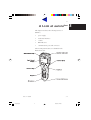


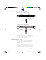

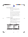

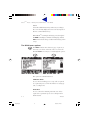


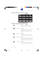


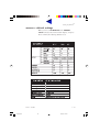


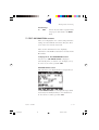


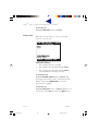
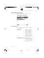


![2 Drücken Sie [OK]. - CONRAD Produktinfo.](http://vs1.manualzilla.com/store/data/006791783_1-b4fb80314e9474e6a94d48a2a3b2e5e9-150x150.png)