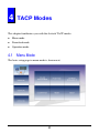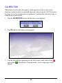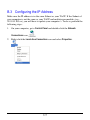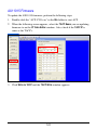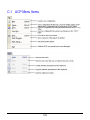
1
TACP-100 User’s Manual
Revision 2.4
(April, 2011)
WARNING
Do not attempt to disassemble your TACP device. Doing so may void your
warranty. There are no serviceable parts inside. Please refer all servicing to
qualified personnel.
TRADEMARKS
All brand and product names are trademarks or registered trademarks of their
respective companies.
COPYRIGHT
The information in this manual is subject to change without prior notice. No part
of this document may be reproduced or transmitted in any form or by any means,
electronic or mechanical for any purpose, without the express written permission
of Avitech International Corporation. Avitech International Corporation may have
patents, patent applications, trademarks, copyrights or other intellectual property
rights covering the subject matter in this document. Except as expressly written
by Avitech International Corporation, the furnishing of this document does not
give you any license to patents, trademarks, copyrights or other intellectual
property of Avitech International Corporation or any of its affiliates.
TECHNICAL SUPPORT
If you have any questions regarding the information provided in this guide, call
our technical support help line at 425-885-3863 or our toll free help line at
1-877-AVI-TECH. You can also email us at [email protected]
Table of Contents
Warranty .............................................................................................. v
Extended Warranty Options ...................................................................... vii
Services and Repairs Outside the Warranty Period ................................. vii
Extended Warranty Options ........................................................................ x
Services and Repairs Outside the Warranty Period ................................... x
Federal Communications Commission (FCC) Statement .......................... xi
European Union CE Marking and Compliance Notices ............................ xii
Statements of Compliance................................................................. xii
Australia and New Zealand C-Tick Marking and Compliance Notice ...... xiii
Statement of Compliance ................................................................. xiii
Welcome .................................................................................................. xiv
About this Manual ..................................................................................... xv
1
Getting Started .............................................................................. 1
1.1 Package Contents ............................................................................... 1
1.2 Product Features ................................................................................. 3
Hardware ............................................................................................. 3
Software ............................................................................................... 4
Specifications ....................................................................................... 4
1.3 Identifying the Front Hardware Components ....................................... 5
1.4 Identifying the Rear Hardware Components ....................................... 6
1.5 Sample Layout Diagram ...................................................................... 7
1.6 Configuration Setup Process ............................................................... 9
1.7 Using the Touch Panel ......................................................................10
1.8 Getting Your TACP Ready for Use ....................................................10
Stand-alone TACP Table Top Setting ...............................................11
Multiple TACP Setting........................................................................13
Rack Mounted TACP Setting .............................................................16
1.9 Setting Up the Avitech Multiviewer Modules .....................................20
2
Avitech Control Panel................................................................. 21
2.1 Introduction ........................................................................................21
i
2.2 Configuring the ACP ..........................................................................24
IP Table Editor ...................................................................................24
Page...................................................................................................26
Setting the Button Attributes ..............................................................34
Writing the Configuration File to TACP..............................................48
3
Communicating With Multiviewers ............................................ 54
3.1 Introduction ........................................................................................54
3.2 Connecting TACP to Modules ...........................................................55
3.3 ACP Run-Time...................................................................................56
4
TACP Modes ............................................................................... 60
4.1 Menu Mode ........................................................................................60
RELEASE ..........................................................................................61
OPERATOR 1 / 2 / 3..........................................................................61
COLOR ADJUSTMENT .....................................................................62
IP SETTING .......................................................................................63
AVITECH MODULES’ IP ...................................................................64
CALIBRATION ...................................................................................65
RESET ...............................................................................................66
ABOUT...............................................................................................67
4.2 Download Mode .................................................................................67
4.3 Operation Mode .................................................................................68
Title Box
...........................................................68
ASCII Z Command Buttons ...............................................................69
Back / Next Buttons
.....................................69
5
Power Down the TACP ............................................................... 70
A
ASCII Z Command ...................................................................... 72
A.1 ASCII Z Command Format ................................................................72
A.2 ACC-8000 ASCII Z Command Format ..............................................73
ZM .......................................................................................................73
ZP .......................................................................................................74
A.3 MCC-8001U ASCII Z Command Format ...........................................74
ZC .......................................................................................................75
ZL .......................................................................................................75
ZM .......................................................................................................76
ZN .......................................................................................................77
ZP .......................................................................................................77
ii
ZR .......................................................................................................78
ZT .......................................................................................................78
ZX .......................................................................................................79
A.4 MCC-8004 ASCII Z Command Format..............................................80
ZA .......................................................................................................80
ZB .......................................................................................................80
ZC .......................................................................................................80
ZE .......................................................................................................81
ZF .......................................................................................................81
ZI .......................................................................................................82
ZK .......................................................................................................82
ZL .......................................................................................................84
ZM .......................................................................................................84
ZN .......................................................................................................86
ZO .......................................................................................................86
ZP .......................................................................................................87
ZR .......................................................................................................87
ZT .......................................................................................................88
ZV .......................................................................................................89
ZW .......................................................................................................89
ZX .......................................................................................................89
A.5 Rainier-2x Series ASCII Z Command Format ...................................90
ZA .......................................................................................................90
ZC .......................................................................................................90
ZF .......................................................................................................91
ZJ .......................................................................................................91
ZL .......................................................................................................92
ZM .......................................................................................................92
ZN .......................................................................................................93
ZP .......................................................................................................93
ZR .......................................................................................................94
ZT .......................................................................................................94
ZW .......................................................................................................95
ZX .......................................................................................................96
A.6 Rainier-4x / 4x1V Series ASCII Z Command Format ........................96
ZC .......................................................................................................96
ZF .......................................................................................................97
ZJ (for Rainier-4a1V / 4d1V only) ........................................................97
ZM .......................................................................................................98
ZP .......................................................................................................98
ZT .......................................................................................................99
iii
ZX .....................................................................................................100
A.7 Rainier-4U / -4U1V ASCII Z Command Format ..............................100
ZC .....................................................................................................100
ZF .....................................................................................................101
ZJ .....................................................................................................101
ZM .....................................................................................................102
ZP .....................................................................................................103
ZT .....................................................................................................103
ZX .....................................................................................................104
A.8 VCC-8000 ASCII Z Command Format ............................................105
ZA .....................................................................................................105
ZC .....................................................................................................105
ZE .....................................................................................................106
ZF .....................................................................................................106
ZI .....................................................................................................106
ZJ .....................................................................................................107
ZK .....................................................................................................107
ZL .....................................................................................................108
ZM .....................................................................................................109
ZN .....................................................................................................110
ZP .....................................................................................................110
ZR .....................................................................................................111
ZT .....................................................................................................112
ZW .....................................................................................................113
ZX .....................................................................................................113
B
Firmware Upgrade .................................................................... 115
B.1 Requirements ..................................................................................115
B.2 Making the Connection ....................................................................115
B.3 Configuring the IP Address ..............................................................117
Checking the TACP’s IP Address ....................................................120
B.4 Updating the Firmware ....................................................................121
AX11015 Firmware ..........................................................................122
WT8882 Firmware ...........................................................................124
C
ACP (More Information) ............................................................ 125
C.1 ACP Menu Items..............................................................................126
C.2 Setting Up the Module(s) IP / COM Port Baud Rate .......................127
iv
1
Getting Started .............................................................................. 1
1.1 Package Contents ............................................................................... 1
1.2 Product Features ................................................................................. 3
Hardware ............................................................................................. 3
Software ............................................................................................... 4
Specifications ....................................................................................... 4
1.3 Identifying the Front Hardware Components ....................................... 5
1.4 Identifying the Rear Hardware Components ....................................... 6
1.5 Sample Layout Diagram ...................................................................... 7
1.6 Configuration Setup Process ............................................................... 9
1.7 Using the Touch Panel ......................................................................10
1.8 Getting Your TACP Ready for Use ....................................................10
Stand-alone TACP Table Top Setting ...............................................11
Multiple TACP Setting........................................................................13
Rack Mounted TACP Setting .............................................................16
1.9 Setting Up the Avitech Multiviewer Modules .....................................20
2
Avitech Control Panel................................................................. 21
2.1 Introduction ........................................................................................21
2.2 Configuring the ACP ..........................................................................24
IP Table Editor ...................................................................................24
Page...................................................................................................26
Setting the Button Attributes ..............................................................34
Writing the Configuration File to TACP..............................................48
3
Communicating With Multiviewers ............................................ 54
3.1 Introduction ........................................................................................54
3.2 Connecting TACP to Modules ...........................................................55
3.3 ACP Run-Time...................................................................................56
4
TACP Modes ............................................................................... 60
4.1 Menu Mode ........................................................................................60
RELEASE ..........................................................................................61
OPERATOR 1 / 2 / 3..........................................................................61
COLOR ADJUSTMENT .....................................................................62
IP SETTING .......................................................................................63
AVITECH MODULES’ IP ...................................................................64
CALIBRATION ...................................................................................65
RESET ...............................................................................................66
ABOUT...............................................................................................67
4.2 Download Mode .................................................................................67
4.3 Operation Mode .................................................................................68
Title Box .............................................................................................68
v
ASCII Z Command Buttons ...............................................................69
Back / Next Buttons ...........................................................................69
5
Power Down the TACP ............................................................... 70
A
ASCII Z Command ...................................................................... 72
A.1 ASCII Z Command Format ................................................................72
A.2 ACC-8000 ASCII Z Command Format ..............................................73
ZM .......................................................................................................73
ZP .......................................................................................................74
A.3 MCC-8001U ASCII Z Command Format ...........................................74
ZC .......................................................................................................75
ZL .......................................................................................................75
ZM .......................................................................................................76
ZN .......................................................................................................77
ZP .......................................................................................................77
ZR .......................................................................................................78
ZT .......................................................................................................78
ZX .......................................................................................................79
A.4 MCC-8004 ASCII Z Command Format..............................................80
ZA .......................................................................................................80
ZB .......................................................................................................80
ZC .......................................................................................................80
ZE .......................................................................................................81
ZF .......................................................................................................81
ZI .......................................................................................................82
ZK .......................................................................................................82
ZL .......................................................................................................84
ZM .......................................................................................................84
ZN .......................................................................................................86
ZO .......................................................................................................86
ZP .......................................................................................................87
ZR .......................................................................................................87
ZT .......................................................................................................88
ZV .......................................................................................................89
ZW .......................................................................................................89
ZX .......................................................................................................89
A.5 Rainier-2x Series ASCII Z Command Format ...................................90
ZA .......................................................................................................90
ZC .......................................................................................................90
ZF .......................................................................................................91
vi
ZJ .......................................................................................................91
ZL .......................................................................................................92
ZM .......................................................................................................92
ZN .......................................................................................................93
ZP .......................................................................................................93
ZR .......................................................................................................94
ZT .......................................................................................................94
ZW .......................................................................................................95
ZX .......................................................................................................96
A.6 Rainier-4x / 4x1V Series ASCII Z Command Format ........................96
ZC .......................................................................................................96
ZF .......................................................................................................97
ZJ (for Rainier-4a1V / 4d1V only) ......................................................97
ZM .......................................................................................................98
ZP .......................................................................................................98
ZT .......................................................................................................99
ZX .....................................................................................................100
A.7 Rainier-4U / -4U1V ASCII Z Command Format ..............................100
ZC .....................................................................................................100
ZF .....................................................................................................101
ZJ .....................................................................................................101
ZM .....................................................................................................102
ZP .....................................................................................................103
ZT .....................................................................................................103
ZX .....................................................................................................104
A.8 VCC-8000 ASCII Z Command Format ............................................105
ZA .....................................................................................................105
ZC .....................................................................................................105
ZE .....................................................................................................106
ZF .....................................................................................................106
ZI .....................................................................................................106
ZJ .....................................................................................................107
ZK .....................................................................................................107
ZL .....................................................................................................108
ZM .....................................................................................................109
ZN .....................................................................................................110
ZP .....................................................................................................110
ZR .....................................................................................................111
ZT .....................................................................................................112
ZW .....................................................................................................113
ZX .....................................................................................................113
vii
B
Firmware Upgrade .................................................................... 115
B.1 Requirements ..................................................................................115
B.2 Making the Connection ....................................................................115
B.3 Configuring the IP Address ..............................................................117
Checking the TACP’s IP Address ....................................................120
B.4 Updating the Firmware ....................................................................121
AX11015 Firmware ..........................................................................122
WT8882 Firmware ...........................................................................124
C
ACP (More Information) ............................................................ 125
C.1 ACP Menu Items..............................................................................126
C.2 Setting Up the Module(s) IP / COM Port Baud Rate .......................127
viii
Warranty
Avitech International Corporation (herein after referred to as “Avitech”)
warrants to the original purchaser of the products manufactured in its facility (the
“Product”), that these products will be free from defects in material and
workmanship for a period of one (1) year or fifteen (15) months from the date of
shipment of the Product to the purchaser. There is a three (3) months grace
period between shipping and installation.
If the Product proves to be defective during the one (1) year warranty period, the
purchaser’s exclusive remedy and Avitech’s sole obligation under this warranty
is expressly limited, at Avitech’s sole option, to:
(a) repairing the defective Product without charge for parts and labor; or
(b) providing a replacement in exchange for the defective Product; or
(c) if after a reasonable time is unable to correct the defect or provide a
replacement Product in good working order, then the purchaser shall be entitled
to recover damages subject to the limitation of liability set forth below.
LIMITATION OF LIABILITY: AVITECH’S LIABILITY UNDER THIS
WARRANTY SHALL NOT EXCEED THE PURCHASE PRICE PAID FOR
THE DEFECTIVE PRODUCT. IN NO EVENT SHALL AVITECH BE
LIABLE FOR ANY INCIDENTAL, SPECIAL, OR CONSEQUENTIAL
DAMAGES, INCLUDING WITHOUT LIMITATION, LOSS OF PROFITS
FOR ANY BREACH OF THIS WARRANTY.
If Avitech replaces the defective Product with a replacement Product as provided
under the terms of this Warranty, in no event will the term of the warranty on the
replacement Product exceed the number of months remaining on the warranty
covering the defective Product. Equipment manufactured by other suppliers and
supplied by Avitech carries the respective manufacturer’s warranty. Avitech
assumes no warranty responsibility either expressed or implied for equipment
manufactured by others and supplied by Avitech.
ix
THIS WARRANTY IS IN LIEU OF ALL OTHER WARRANTIES
EXPRESSED OR IMPLIED, INCLUDING WITHOUT LIMITATION, ANY
IMPLIED WARRANTY OF MERCHANTABILITY OR FITNESS FOR A
PARTICULAR PURPOSE, ALL OF WHICH ARE EXPRESSLY
DISCLAIMED.
This Hardware Warranty shall not apply to any defect, failure, or damage:
(a) caused by improper use of the Product or inadequate maintenance and care of
the Product;
(b) resulting from attempts by other than Avitech representatives to install,
repair, or service the Product;
(c) caused by installation of the Product in a hostile operating environment or
connection of the Product to incompatible equipment; or
(d) caused by the modification of the Product or integration with other products
when the effect of such modification or integration increases the time or
difficulties of servicing the Product.
Any Product which fails under conditions other than those specifically covered
by the Hardware Warranty, will be repaired at the price of parts and labor in
effect at the time of repair. Such repairs are warranted for a period of ninety (90)
days from date of reshipment to customer.
Extended Warranty Options
Avitech offers OPTIONAL Extended Warranty plans that provide continuous
coverage for the Product after the expiration of the Warranty Period. Contact an
Avitech sales representative or details on the options that are available for your
Avitech equipment.
Services and Repairs Outside the Warranty Period
Avitech make its best offer to repair products that is outside the warranty period,
provided the product has not reached its end of life (EOL). The minimum charge
for such repair excluding shipping and handling is $200 (US dollars).
AVITECH INTERNATIONAL CORPORATION ● 8655 154th Ave NE ● Redmond, WA ● 98052 ● TOLL FREE 1 877 AVITECH
PHONE 1 425 885 3863 ● FAX 1 425 885 4726 ● [email protected] ● www.avitechvideo.com
x
Regulatory Information
NOTE: Marking labels located on the exterior of your device indicate the regulations that
your model complies with. Please check the marking labels on your device and refer to the
corresponding statements in this chapter. Some notices apply to specific models only.
Federal Communications Commission (FCC)
Statement
This equipment has been tested and found to comply with the limits for a Class A
digital device, pursuant to Part 15 of the FCC Rules. These limits are designed to
provide reasonable protection against harmful interference when the equipment
is operated in a commercial environment. This equipment generates, uses, and
can radiate radio frequency energy and, if not installed and used in accordance
with the instruction manual, may cause harmful interference to radio
communications. Operation of this equipment in a residential area is likely to
cause harmful interference, in which case the user will be required to correct the
interference at his own expense.
Properly shielded and grounded cables and connectors must be used in order to
meet FCC emission limits. Avitech is not responsible for any radio or television
interference caused by using other than recommended cables and connectors or
by unauthorized changes or modifications to this equipment. Unauthorized
changes or modifications could void the user's authority to operate the
equipment.
Operation is subject to the following two conditions: (1) this device may not
cause harmful interference, and (2) this device must accept any interference
received, including interference that may cause undesired operation.
xi
European Union CE Marking and Compliance Notices
Statements of Compliance
English
This product follows the provisions of the European Directive 1999/5/EC.
Danish
Dette produkt er i overensstemmelse med det europæiske direktiv 1999/5/EC.
Dutch
Dit product is in navolging van de bepalingen van Europees Directief
1999/5/EC.
Finnish
Tämä tuote noudattaa EU-direktiivin 1999/5/EC määräyksiä.
French
Ce produit est conforme aux exigences de la Directive Européenne 1999/5/EC.
German
Dieses Produkt entspricht den Bestimmungen der Europäischen Richtlinie
1999/5/EC.
Greek
To προϊόν αυτό πληροί τις προβλέψεις της Ευρωπαϊκής Οδηγίας 1999/5/EC.
Icelandic
Þessi vara stenst reglugerð Evrópska Efnahags Bandalagsins númer 1999/5/EC.
Italian
Questo prodotto è conforme alla Direttiva Europea 1999/5/EC.
Norwegian
Dette produktet er i henhold til bestemmelsene i det europeiske direktivet
1999/5/EC.
Portuguese
Este produto cumpre com as normas da Diretiva Européia 1999/5/EC.
Spanish
Este producto cumple con las normas del Directivo Europeo 1999/5/EC.
Swedish
Denna produkt har tillverkats i enlighet med EG-direktiv 1999/5/EC.
xii
Australia and New Zealand C-Tick Marking and
Compliance Notice
Statement of Compliance
This product complies with Australia and New Zealand's standards for radio
interference.
xiii
Preface
Welcome
Congratulations on purchasing the Avitech TACP-100 (Touch-screen Avitech
Control Panel).
The TACP is a touch sensitive display device that controls Avitech multiviewer
modules or module groups. It is equipped with 7-inch, color active TFT LCD
display that supports 800×480 resolution. This is the perfect control panel for
mobile or temporary installation where the use of a computer for control is not
practical. The TACP can be surface or rack mounted.
The TACP is capable of directly communicating with up to 120 Avitech
multiviewer modules over seven different IP address and one RS-232
connections. Easily control multiple systems in various deployment
combinations through one single TACP. In addition, TACP has peer-to-peer
communication capability; allowing you to create TACP networks and expand to
extremely large and complex systems any time over Ethernet communication.
Using the Avitech ASCII Protocol (also known as Z commands), the TACP
supports all model lines of Avitech multiviewer modules – allowing you to recall
up to 26 pre-configured screen settings from each group of multiviewers,
providing ease of use to Avitech multiviewer users.
Using the Avitech software Control Panel (ACP), the TACP can completely
reflect all buttons and layouts, allowing it to share the same look and feel as the
ACP even after the transformation. Each TACP also allows you to save up to
three configurations.
xiv
This manual contains comprehensive information about your Avitech
TACP-100 to help you operate the device. It is divided into four chapters and
three appendices.
Chapter 1, Getting Started, gives you an overview of the TACP as well as
identify its external components.
Chapter 2, Avitech Control Panel, shows you how to create the
configurations using the Avitech Control Panel (ACP) and save it to the
TACP.
Chapter 3, Communicating With Multiviewers, tells you how to use the
TACP to communicate with Avitech multiviewers.
Chapter 4, TACP Modes, lets you know the basic controls of the TACP.
Appendix A, ASCII Z Commands, provides you the complete lists of Z
command lines.
Appendix B, Firmware Upgrade, provides instructions on how to update
the TACP firmware.
Appendix C, ACP (More Information), provides additional information
about the ACP (Avitech Control Panel).
NOTE: For the administrator who needs to create configuration and edit the layouts, you
may start from Chapter 2 to begin setup. However, if you are an operator who performs the
TACP controls, you may start from Chapter 3.
About this Manual
Throughout the manual, the following conventions are used to distinguish
elements of text.
NOTE: provides additional hints or information that requires special attention.
CAUTION: identifies important information which, if not followed, may result in loss of data
or damage to your device.
Any name of menu, command, icon or button that you can see on the screen is
shown in a bold typeset. For example:
On the Start menu, select Settings.
xv
1
Getting Started
This chapter introduces you to the features and specifications as well as the
external components of your Avitech TACP. It also guides you through the
process of setting up your TACP for use.
NOTE: Depending on the model you purchased, the cabinet color and the look of the
accessories may be different from the ones shown in this manual.
1.1 Package Contents
After unpacking the shipping carton, you should find these standard items:
Avitech TACP
5 V DC Power Adapter
1
6 feet Category 5 Ethernet Cable
Proprietary RJ-45 to RS-232 (DB9-FM) Cable
(Refer to the “NOTE” below.)
3 RU Rack Mount Face Plate (optional)
Set of Screws (optional)
RS-232 Splitter Cable (optional)
(Refer to the “NOTE” below.)
Utility Disc (contains software and user’s manual)
Quick Start Guide
2
NOTE:
When the TACP is connected to the MCC-8001U, ACC-8000, and Rainier-4U1V; and
RS-232 is selected as the communication port, a RS-232 splitter cable is required.
Due to space limitation, the serial connector is replaced with a RJ-45 connector. A
proprietary RJ-45 to RS-232 (DB9-FM) cable is needed for serial function. The pin
definition is shown next.
DB9-FM
Pin
RJ-45
Assignment
Pin
1
Assignment
1
Tx
2
Tx
2
Gnd
3
Rx
3
4
5
Gnd
4
Rx
5
Gnd
6
6
7
7
8
5V
8
9
1.2 Product Features
Hardware
Direct communication with up to 120 modules on one TACP
(including seven IP and one RS-232 connection).
Peer-to-peer communication among TACPs.
Ethernet and serial connectivity.
3
5V
Surface or rack-mounted
(optional 3 RU rack mount face plate upon request).
Compatible with all Avitech product lines.
Software
Direct download grouping function from ACP over IP.
Recall preset functions with just one push of a button.
Using the ACP, the user interface on the TACP is customizable. The editable
items include the display background, button style, button label, button size,
location, Z command in each button, and the font size and color.
Specifications
Parts
I/O interface
Operating
mode
Single
One TACP with up to seven sets of multiviewers under different IP
addresses and one set through RS-232 communication.
Multiple
Peer-to-peer communication with combination of TACP and ACP.
Touch panel
Power
Specifications
IP for communicating with multiviewers and the computer
RS-232 for communicating with multiviewers and the computer
7-inch active matrix a-Si TFT (Thin-Film Transistor) color LCD display
800×480 pixel resolution
Resistive-type 4 wires
152.4×91.44 mm (6×3.6 inch) active area
0.0635×0.1905 mm (0.002×0.008 inch) pixel pitch
Anti-glare overlay
Finger or stylus pen input method
Operating
Voltage
Connection
Housing
Dimension (W×H×D)
Weight
Accessories
5 V DC
External DC input
Metal
232.6×132×45.0 mm (9.16×5.20×1.77 inch)
0.75 kg (1.7 lb)
6 feet category 5 Ethernet cable
6 feet RJ-45 to RS-232 cable
5 V DC power adapter
Quick Start Guide
Utility disc
3 RU rack mount face plate (divided into two pieces)
with set of screws (optional)
4
Parts
Environment Temperature
Humidity
Safety regulations
Software
Specifications
Operating: 0 °C (32 °F) to 50 °C (122 °F)
Storage: –10 °C (–4 °F) to 60 °C (140 °F)
0 % to 80 % relative, non-condensing
Maximum wet temperature: 35 °C (95 °F)
FCC / CE / C-Tick, Class A
Avitech Control Panel (ACP)
Minimum supported version: V2.01 (dated 05/01/2009)
Operating System compatibility:
Microsoft Windows 2000, XP, Vista, Server 2003, Server 2008
IMPORTANT for Windows 2000 user: download the plug-in
(gdiplus.dll) from the Microsoft® website at
http://www.microsoft.com/downloads/details.aspx
?FamilyID=6a63ab9c-df12-4d41-933c-be590feaa05a&
displaylang=en and follow the on screen instructions to install it.
1.3 Identifying the Front Hardware Components
5
1.4 Identifying the Rear Hardware Components
6
1.5 Sample Layout Diagram
The following illustration shows a sample ACP + TACP peer-to-peer system
connection.
The TACP can control multiviewer systems via itself, the ACP, as well as
another TACP in one network. The ACP not only allows you to create the
configuration, but also perform run-time communication with the multiviewer
systems.
7
The following illustration shows a single TACP in a multiple multiviewer
system.
The TACP can control the multiviewer system independently once the
configuration has been downloaded from the ACP.
Each TACP is capable of controlling the multiviewer system from seven
different IP over the Ethernet switch. Also, one RS-232 connection allows you to
directly connect to another group of multiviewer system.
8
1.6 Configuration Setup Process
The following diagram shows you the typical configuration setup process.
First Step: Setup IP address for the TACP and multiviewers that the TACP will
communicate with.
Second Step: Create the configuration, including setting page layouts, buttons,
and assigning Z commands.
Third Step: Pass the configuration to the TACP. Make sure the TACP is in the
same Ethernet network as the ACP.
Last Step: Connect the TACP with the modules; you can then control the
multiviewers.
9
1.7 Using the Touch Panel
The touch panel is a touch-sensitive device that allows you to easily
communicate with the TACP. The 7-inch touch panel is a resistive-type 4 wire
touch-screen. It is suggested to use your finger tip, stylus, or pen tip to tap on the
screen for better response.
1.8 Getting Your TACP Ready for Use
The Avitech TACP can be set up in any three ways namely:
Stand-alone TACP table top setting
Multiple TACP setting
Rack mounted TACP setting
10
Stand-alone TACP Table Top Setting
To set up a stand-alone table top Avitech TACP, perform the following steps:
1. Unpack the TACP from the EPE bag and set the stainless steel kick stand at
approximately 60 degree angle on a steady surface.
2. Unpack the 5 V 3 A DC power adapter from the box and plug the DC cord of
the power adapter to the power jack on the rear of the TACP. Rotate the
locking screw clockwise to ensure it is firmly screwed into the power jack.
3. Plug the power adapter to an electrical outlet. When the power adapter is
connected, power is being supplied from the electrical outlet to the power
adapter and onto your TACP.
4. Make sure both dip switches are set to the off position (flip up).
5. Turn on the TACP by pressing the power switch
11
to the “I” (on) position.
6. Perform screen calibration (when using your TACP for the very first time).
Use your finger tip or a stylus to tap on the four red cubes appearing on the
four corners of the touch panel. Make sure the color of each cube turns from
red
to green
.
7. When it is finished, you will see the menu mode main page loading up.
8. Connect the Ethernet cable to the Ethernet port on the TACP and the other
end to the computer or the Ethernet switch / hub.
12
9. Make sure the power LED and the connection LED glows yellow. When the
power is on but the network connection is down, the connection LED will be
off and the power LED will glow orange.
Power Indicator
Glows yellow when the TACP has an available
connection to LAN.
Glows orange when the power is on but the
connection to LAN is down.
Connection Indicator
Glows / blinks yellow when the TACP has an
available connection to LAN / is accessing the LAN.
Is off when the connection to LAN is down.
Multiple TACP Setting
To set up multiple Avitech TACP, perform the following steps:
1. Unpack the TACP from the EPE bag and set the stainless steel kick stand at
approximately 60 degree angle on a steady surface.
13
2. Unpack the 5 V 3 A DC power adapter from the box and plug the DC cord of
the power adapter to the power jack on the rear of the TACP. Rotate the nut
clockwise to ensure it is firmly screwed into the power jack.
3. Plug the power adapter to an electrical outlet. When the power adapter is
connected, power is being supplied from the electrical outlet to the power
adapter and onto your TACP.
4. Make sure both dip switches are set to the off position (flip up).
5. Turn on the TACP by pressing the power switch
to the “I” (on) position.
6. Perform screen calibration (when using your TACP for the very first time).
Use your finger tip or a stylus to tap on the four green dots appearing on the
four corners of the touch-screen. Make sure the color of each dot turns from
red
to green
.
14
7. When it is finished, you will see the menu mode main page loading up.
8. Connect the Ethernet cable to the Ethernet port on the TACP and the other
end to the Ethernet switch / hub.
NOTE: It is highly recommended that you connect the TACP to a clean local area network
(LAN) to ensure a steady connection throughput.
9. Perform steps 1 to 8 for the other TACPs that will be used.
10. Make sure the power LED and the connection LED glows yellow. When the
power is on but the network connection is down, the connection LED will be
off and the power LED will glow orange.
15
Power Indicator
Glows yellow when the TACP has an available
connection to LAN.
Glows orange when the power is on but the
connection to LAN is down.
Connection Indicator
Glows / blinks yellow when the TACP has an
available connection to LAN / is accessing the LAN.
Is off when the connection to LAN is down.
Rack Mounted TACP Setting
To set up the rack-mounted Avitech TACP, perform the following steps:
1. Unpack the TACP from the EPE bag and carefully place the TACP face
down on the desk.
2. Unpack two pieces of rack mount face plate from the paper carton.
3. Pull out the stainless steel kick stand to a 90 degree angle so that it is
perpendicular with the TACP’s LCD panel.
16
4. Place one piece of the rack mount face plate beside the TACP (still facing
down) so that the two screw holes located on the face plate are aligned with
the screw holes located on the side of the TACP.
5. Repeat the same steps for the other side.
Upon securing the screws, this is what the front view looks like.
6. Secure the rack mount panel to the server rack.
7. Unpack the 5 V 3 A DC power adapter from the box and plug the DC cord of
the power adapter to the power jack on the rear of the TACP. Rotate the nut
clockwise to ensure it is firmly screwed into the power jack.
8. Make sure both dip switches are set to the off position (flip up).
17
9. Plug the power adapter to an electrical outlet. When the power adapter is
connected, power is being supplied from the electrical outlet to the power
adapter and onto your TACP.
10. Turn on the TACP by pressing the power switch
to the “I” (on) position.
11. Perform screen calibration (when using your TACP for the very first time).
Use your finger tip or a stylus to tap on the four green dots appearing on the
four corners of the touch-screen. Make sure the color of each dot turns from
to green
.
red
18
12. When it is finished, you will see the menu mode main page loading up.
13. Connect the Ethernet cable to the Ethernet port on the TACP and the other
end to the computer or the Ethernet switch.
14. Make sure the power LED and the connection LED glows yellow. When the
power is on but the network connection is down, the connection LED will be
off and the power LED will glow orange.
Power Indicator
Glows yellow when the TACP has an available
connection to LAN.
Glows orange when the power is on but the
connection to LAN is down.
Connection Indicator
Glows / blinks yellow when the TACP has an
available connection to LAN / is accessing the LAN.
Is off when the connection to LAN is down.
19
1.9 Setting Up the Avitech Multiviewer Modules
To setup the Avitech multiviewer modules, perform the following steps:
1. Cascade the Avitech multiviewer modules by following the installation
instruction from the respective product user’s manual.
2. Launch the Galaxy program to assign the Avitech multiviewer module’s
hardware configuration such as group ID, module ID, output display layout,
connection setting, etc. Then save the new configuration to flash memory
before exiting the Galaxy program.
IMPORTANT: You are advised to take note of the IP address and / or baud rate setting of
the respective Avitech modules that you will connect to.
20
2
Avitech Control Panel
This chapter familiarizes you with configuring the Avitech Control Panel (ACP)
software for use.
2.1 Introduction
To create the configuration files for the TACP, you need to run the Avitech
software Control Panel (ACP). The supported operating systems are Microsoft
Windows XP, Windows Vista, Windows Server 2003, Windows Server 2008,
and Windows 2000.
IMPORTANT (for Windows 2000 user): download the plug-in (gdiplus.dll) from
the Microsoft® website at
http://www.microsoft.com/downloads/details.aspx?FamilyID=6a63ab9c-df12-4d41-9
33c-be590feaa05a&displaylang=en and follow the on screen instructions to install it.
21
The ACP application files are found in three folders on the included utility disc
(under the “ACP_yyyymmdd” folder) or can be downloaded from the Avitech
web site, copy and save these to the host computer –
Bin folder: where the program “ACP-V201.exe” is located.
TACP folder: where the final configuration is recommended to be saved.
Templates folder: where the graphic images are stored.
NOTE: It is highly recommended to set the screen resolution at 1280×1024 when using the
ACP.
22
To start using the ACP, double-click “ACP-V201.exe” in the Bin folder. The
following screen appears.
The blue background is an 800×480 window, which is the same dimension as the
touch panel. From here, you will create your own graphic layout (hereafter called
a page) for the TACP. What you see is what you get when you finish the page(s)
layout and send it to the TACP. This means that what you see on this 800×480
window will be completely copied over.
The TACP Editor window performs the function of creating each 800×480 page,
and of transferring the configured pages (hereafter called a configuration).
The first step in setting up the configuration is via the IP Table Editor window.
23
2.2 Configuring the ACP
IP Table Editor
Upon starting the ACP, create a new TACP IP table first. To create a new IP
table, perform the following steps:
1. On the IP Table Editor window, enter a name on the New TACP window to
create a new TACP account. Then click the Add button.
2. Remove any unwanted TACP name by clicking the TACP Name drop-down
list and selecting the particular name, then click Delete.
3. Enter the IP address for your TACP. Or, use the computer’s IP address that
you are using to communicate to the connected modules.
24
4. Enter the IP address(es) of the multiviewer modules that will be connected to
the TACP. Each TACP can directly communicate with up to seven IP
addresses and one RS-232 connection. Then enter a name to help you
identify each module (optional).
NOTE: The Avitech Modules IP Address is the IP address of the master module (the
Avitech module that is communicating with the TACP through a direct cable connection) for
each cascaded system.
5. Select the COM port baud rate if connecting to a module via RS-232 cable.
The default baud rate for all Avitech
multiviewer modules is 57600 bps (except Rainier-4x1V RS-232 series).
NOTE: The default baud rate for the Rainier-4x1V (RS-232) series is 115200 bps.
6. Click OK to apply the settings or click Cancel to discard the changes and exit
the IP Table Editor screen.
NOTE:
Click Save to store the IP table list and save the current IP setting for future use. You will
be prompted to create a filename (e.g., by typing TACP_01 the filename
TACP_01.dat would be created).
Click Open to retrieve the pre-saved IP table list.
25
Page
Add New Page
Upon clicking the Add New Page button, the following window appears.
Function
Description
Page Name
Assign a name for the new page which can help identify the
purpose of the page.
Change Image
(Background
Image)
Upon clicking this button the Image Selector window will pop up.
You can search the Background folder under the Templates
directory. You can also search from the directory tree of the entire
computer for the desired background image. The accepted
graphic formats are: BMP, PNG, JPG, and TIFF.
NOTE: To change the background image in the future, just double-click
anywhere on the background and the Page Properties window appears.
26
Function
Description
Change Image
(Color Palette)
Upon clicking this button the Color Selection Palette menu will
pop up. You may select from the commonly used color table or
click More Colors for more selection.
Layout
(Row × Column)
The two drop-down selector allows you to customize the display
matrix for the operation buttons appearing on the page (e.g.,
selecting 2×3 will produce a 6 button layout in a 2 by 3 matrix on
this page) and will automatically scale the buttons to fill up the
page. Therefore, the more buttons displayed on one page, the size
of each button will initially turn out smaller. However, the size of
each button is customizable, movable, and removable after
creation.
Change Image
Upon clicking this button the Image Selector window will pop up.
You can search the Button folder under the Templates directory.
You can also search from the directory tree of the entire computer
for the desired button image. The accepted graphic formats are:
BMP, PNG, JPG, and TIFF.
“Un-pressed” refers to the inactive state of the button.
”Pressed” refers to state when using the fingertip or stylus to tap
on the button.
(Un-pressed
Image)
(Pressed Image)
NOTE: To change the button image in the future, right-click the particular
button and select Button Properties to modify it.
27
After making the desired selections click OK and the following 800×480 pixel
window with customized layout will appear.
28
Add New Button
Upon clicking the Add New Button button on the TACP Editor window, a new
button having the same attributes as the previously set buttons would appear on
the middle of the screen.
29
Moving and Re-sizing Button
To move the particular button, use the mouse to click and highlight it. Place the
mouse over the button and a cross symbol will appear. Click and hold the mouse
button until the on screen button moves to the desired location.
To re-size the button, use the mouse to click and highlight it. Move the mouse to
the border of the button until an arrow sign appears, click and drag the mouse
button to change to the desired size.
30
Press the Ctrl key and click the mouse button to select multiple on screen buttons.
You can also use the above method to drag or re-size multiple buttons.
Copy / Paste Buttons
Right-click a particular button, then select copy.
Then click Paste and the duplicate button appears.
Group / Ungroup Buttons
31
Press and hold the Ctrl key and click multiple buttons to group multiple buttons.
You can also right-click and drag the mouse button to highlight the enclosed on
screen buttons. Then right-click the mouse on the grouped buttons; and click
Group. The grouped buttons will retain its grouping until you select Ungroup.
Grouped buttons can be moved, re-sized, as well as change its global properties
at the same time.
Align
By clicking to select more than one button allows you to perform button
alignment. Click Left to align buttons to the left border of the last button. Click
Top to align buttons to the top border of the last button.
Distribute
32
By clicking to select three or more buttons, you can use the Distribute function.
Selecting Equal Horizontal / Vertical Space allows you to spread the page with
evenly spaced buttons.
Selecting Equal Horizontal / Vertical Center allows you to spread the buttons on
the page from the center of one button to another.
Select All
Right-clicking the mouse on any button on the screen and clicking Select All will
highlight all the buttons.
Delete Button
To remove or delete a particular button, right-click the mouse on the selected
button, then select Delete. Or, press the Delete key on the keyboard after selecting
the button.
33
Undo / Redo
Upon clicking the Undo button (or press Ctrl + Z), it allows you to cancel the last
action including button resize, location, delete, add page, delete page,
background, and order settings. The Redo button (or press Ctrl + Y) allows you to
redo the previous action that was cancelled by the Undo button. The Undo / Redo
button allows you to cancel or redo unlimited steps.
Setting the Button Attributes
To set up the button attributes, perform the following steps:
1. Right-click the mouse on the button you want to set the attributes and click
Properties.
34
2. The following screen appears. On the Type portion, you may assign the
button type.
Z-Command: button that stores the ASCII command lines.
Text: contains the text box for the title.
Next / Previous Page: button for turning the page.
35
3. On the Image and Text portion, you may want to change the image for both
Un-pressed and Pressed buttons; add text by entering it on the Text on Button
window, change the font style by clicking on Font, and set the font color by
clicking on the Color drop-down menu.
On the Position and Size portion, you may want to fine tune the button’s
position and size by entering values on the Horizontal Position, Vertical
Position, Width, and Height windows. Then click Set.
NOTE: The value of the button position and size has to be in increments of eight pixels. If
the value you enter is not divisible by eight, ACP will automatically set the lower number
that is divisible by eight as the final value (e.g., if you entered 47, ACP will then set it as 40).
36
4. On the Z-Command portion, click the TACP drop-down menu to select the
desired TACP, and click the Connect to drop-down menu to select the
connecting IP address (left figure below). Or, select RS-232 when using a
serial connection. Then click the Add Instruction button and you will see a
message string with an IP address in the instruction box. Also, the
Z-Command Editor button becomes active.
Connect to IP
Connect to RS-232
For example, on the instruction box above “210.100.100.200” is the TACP’s
IP address and “IP1” is the connected module’s IP #. This means that the
“IP1” interface of TACP with IP address “210.100.100.200” will send out
the below Z command.
37
For example, on the instruction box above “210.100.100.200” is the TACP’s
IP address and “COM” is the connected module. This means that the
“COM” interface of TACP with IP address “210.100.100.200” will send out
the below Z command.
5. If you are familiar with the ASCII Z commands, you can enter the Z
command under the IP address text string (for more information on the
ASCII Z commands, refer to a later chapter).
Connect to IP
Connect to RS-232
38
6. If you prefer to use the GUI (graphical user interface) Z command generator,
click the Z-Command Editor button. The following Z-Command Editor
window appears.
7. Select the Module Type by clicking on the radio button, click on the
Command and Attribute drop-down menus to select the desired Z command
and its attribute. Then select the Group, Module, and Processor that you wish
to send the Z command to. Select the Parameter 1 and 2 to complete the
setting (some Z commands will have more parameters to setup).
39
8. Click the Generate button to display the ASCII Z command on the Z
Command portion.
9. Click the Send button to send the Z command back to the instruction box in
the Button Properties window.
40
10. On the Connect section, select the connection method (Serial Port or IP – see
the NOTE below) and click Connect to link the configuring computer to the
module.
NOTE:
Selecting the IP connection method will allow detection of the master module type, but
selecting Serial Port will not.
When selecting the Serial Port connection method, make sure to select the correct
COM port and Baud rate setting (default baud rate for all Avitech multiviewer modules is
57600 bps (except Rainier-4x1V RS-232 series). The default baud rate for the
Rainier-4x1V (RS-232) series is 115200 bps.
11. To test the Z command on the module, click the Testing button.
12. Repeat the above steps if you wish to add more than one command to each
button.
13. If within the same button, you wish to send Z command to a different module
with a different IP address, return to the Z-Command portion of the Button
Properties window. Change the IP address on the Connect To drop-down
menu, then click Add Instruction, and add the Z command that you wish to
send to that IP address.
41
14. For multiple TACP / ACP setup, one button can contain multiple Z
commands to various TACP.
Properties (Global Button)
Right-click the mouse on any button and select Properties to access Global
Button Properties page. Global Button Properties allows you to change the
grouped button’s image, font, and font color. Only the options selected (with
checkmark on the checkbox) will the button’s properties be set.
42
The following shows a sample finished page.
Add New Page
Click Add New Page to create more page layouts.
Sort Pages
Upon clicking the Sort Pages button, the Page Sort window will appear on screen
allowing you to switch the page sequence after creating multiple pages. Click to
highlight the page you wish to swap the order, and then use the arrow buttons to
move forward or backward. You may also use the mouse to drag-and-drop the
page to change the page order.
Press the Delete Page button to remove the unwanted page. Or, press the Delete
key on the keyboard to delete the highlighted page.
43
One click on the selected page will bring up that page to the main window.
Page Right-click Menu
Upon right-clicking the mouse anywhere on the page, the following menu will
pop-up.
Select Cut / Copy / Paste to remove (Cut) or duplicate (Copy / Paste) a page,
including the graphic layout and Z commands.
Select Previous Page / Next Page to move the position of the present active page
to the previous or next page.
Select First Page / Last Page to move the position of the present active page to
the first or last page.
Select All Pages will highlight all the pages.
Select Delete to delete the whole page.
44
Select Grid to display the grid dots as guide lines to help you align the buttons on
the page.
Select Properties and the Page Properties window will pop up. This allows you
to change the Page Name (title) and the background image.
TACP Editor Dialog – Save As
Upon clicking the Save As button on the TACP Editor window, the Save As
window will appear on screen allowing you to save the current ACP (*.TACP)
file. The default filename would be the title of the page.
45
TACP Editor Dialog – Open File
Upon clicking the Open File button on the TACP Editor window, the Open
window will appear on screen allowing you to open a previously saved ACP
(*.TACP) file.
TACP Editor Dialog – Simulation
Upon clicking the Simulation button on the TACP Editor window, the TACP
Simulator window will pop-up. This allows you to run the button function tests
before downloading the configuration to the TACP.
The main window shows the page you just created.
The Avitech Module Connect portion allows you to select which TACP you wish
to simulate.
46
Upon selecting the desired TACP, the corresponding module’s IP Address will
be displayed. Make sure the modules shown are the ones you are going to
connect to and they are set with the correct IP Address. If not, return to the IP
Table Editor to update the IP address. Or modify the IP address on the modules
(refer to Appendix C for instructions on how to change the module IP).
Connect the Ethernet cable between the TACP and the modules. During multiple
IP connection, the Ethernet switch / hub is required.
Click the Connect button when everything is ready.
Each IP connection will take about four seconds so the total connection time
when connecting to seven IPs may take up to 30 seconds. When the connection is
set, the Status column will change from Off-line to OK.
NOTE: A serial port connection will not perform the connection check.
If after 30 seconds has elapsed and the connection still cannot be set, try again by
clicking the Connect button. Or, click Quit to exit and check the physical IP
setup.
47
Writing the Configuration File to TACP
This section shows you how to transfer the configuration file to the TACP.
Setting Up the TACP
1. Power on the TACP and the main page will be displayed. Tap the IP Setting
button to access the IP setting page.
2. Use arrow keys to move to the column you wish to change.
3. Use the on screen keypad to change the number.
4. Set your TACP’s IP address, Netmask, and Gateway address on the IP Editor
window
(e.g., IP: “210.100.100.210;” Netmask: “255.255.255.0;”
Gateway: “210.100.100.254”).
48
5. Click the OK button when finished.
6. The next screen will appear. When it is done, the TACP will automatically
re-start.
NOTE: For more information on how to configure the IP address from the computer, refer to
Appendix C.
49
From the ACP to the TACP
Return to the ACP and click the Write to TACP button to access the TACP Write
window.
50
1. Select your TACP name from the Name drop-down menu. Check if the IP
Address is same as the TACP’s you just set up.
2. Select Operator_1 – Operator_3 on the TACP Configuration Update section.
Click Connect to connect to the TACP over IP.
NOTE: The following are the configuration size limitations:
Maximum configuration size: 192 KB.
Graphic button and layout – 1 MB.
Z command instruction string size limitation for each button is 4 KB.
One TACP can save up to three different configurations (with the same module’s IP
table).
51
3. When the ACP and the TACP is connected, the progress bar will turn green.
4. Click Burn to burn the configuration, including the IP address table, page
layouts, buttons, and Z command strings to the TACP.
NOTE: Click Burn IP Table only if you have already sent out the configuration but wish to
update the IP address only.
52
Checking the TACP
1. When the TACP is receiving files, it will show the following message.
2. When it is done, it will go back to menu mode main page.
53
3
Communicating With
Multiviewers
This chapter familiarizes you with setting up the computer to communicate with
multiviewers.
3.1 Introduction
Each TACP can directly communicate with multiviewer modules via seven
different IP and one RS-232 connection. You can use the ACP to assign the IP
address for each multiviewer module or multiviewer module groups. Within
each IP and RS-232 connection you can cascade up to 15 multiviewer modules.
Peer-to-peer communication functionality extends the controlling power of the
TACP. For example, when TACP 1 is sending the ASCII commands to
multiviewer modules belonging to TACP 2, TACP 1 will pass the commands to
the IP addresses for both TACP 2 and multiviewer modules belonging to TACP
2. After TACP 2 receives the request packet, it will decompress the packet and
then send out commands to the designated multiviewer modules belonging to it.
The ACP also supports run time peer-to-peer communication capability. Just by
clicking on a pre-configured “xxx.tacp” file, you can start controlling
multiviewers right from your computer.
54
3.2 Connecting TACP to Modules
NOTE: Before connecting the TACP and the modules, make sure to set the modules’ IP
addresses first (refer to Appendix C for details).
1. Unplug the Ethernet cable originally connecting the ACP to the TACP from
the computer end, and then connect it to the module’s IP port. So that now
the TACP and the modules are connected via the Ethernet cable.
2. Make sure that the TACP is powered on.
3. Tap the OPERATOR 1 − 3 button on menu mode.
55
4. The IP disconnection indicator will initially show on the panel indicating no
connection.
NOTE: It normally takes about four seconds for each IP to make the connection. The
network bandwidth will affect the connection speed and quality.
5. The panel will be ready to use when the IP disconnection indicator
disappears from the screen.
NOTE: Make sure all slave modules have the same baud rate as the master module to
allow the Z commands to be passed from the master module to the slave modules (refers to
Avitech modules that are cascaded with the master module and also accepts Z commands
passed by the master modules) over a RS-485 cascade cable.
3.3 ACP Run-Time
The ACP Run-Time feature allows the computer to function as a TACP. This
allows the computer to perform module communication without the need to pass
the configuration information through the TACP by performing the following
steps:
Set up the configuration
1. On the IP Table Editor window, assign a name for your ACP and set the
computer’s IP address as the TACP’s IP address.
56
2. Create new button(s) and edit the page layout (see Chapter 2 for details).
3. Upon saving the configuration to the computer, a new file “xxx.tacp” will be
created.
4. Exit the ACP program before going to the next step.
Execute the ACP Run-Time
1. Connect the computer to the multiviewer modules over IP or via RS-232.
2. Double-click the “xxx.tacp” file to start ACP Run-Time.
NOTE: If you receive this xxx.tacp file from another computer, select ACP as the
program to open it.
57
3. The IP disconnection indicator will initially show on the panel indicating no
connection.
4. The panel will be ready to use when the IP disconnection indicator
disappears from the screen.
5. When you see the following error, go back and run “ACP-Vxxx.exe” to
confirm if the IP address of the TACP is the same as the local IP address of
your computer.
58
6. If the ACP Run-Time detects more than one IP address from the computer
that match the IP addresses found on the “.tacp” file, the following window
will pop-up and prompt you to select one TACP.
7. On the Avitech Modules Connect portion, select one TACP and click START.
8. When there is COM port communication, the Avitech Modules Connect
portion will also show up and prompt for COM port # selection.
9. Every two minutes, ACP Run-Time will probe the Ethernet connection to
confirm if the connections are still active.
IMPORTANT: When connecting your TACP to the MCC-8001U or Rainier-4x1V series
(RS-232) modules, make sure to reboot your TACP if you have rebooted your modules.
Upon rebooting your MCC-8001U or Rainier-4x1V series (RS-232) modules, the module
will revert back to Normal mode. Rebooting your TACP while still connected to the modules
would cause the TACP to send a signal that allows the modules to enter the Z command
mode again.
59
4
TACP Modes
This chapter familiarizes you with the Avitech TACP modes:
Menu mode
Download mode
Operation mode
4.1 Menu Mode
The basic setup page in menu mode is shown next.
60
The basic setup page in menu mode that is currently not connected is shown
next. By clicking any OPERATOR button, the TACP will start the attempt to
connect to the TACP.
RELEASE
Before pressing the power switch button on the rear of the TACP to turn off
power, tap the RELEASE button to release the IP connection between the TACP
and the modules in order to properly turn off the TACP.
OPERATOR 1 / 2 / 3
When updating the configurations to the TACP, you can assign the configuration
to be under one of the operator. Selecting any one of the operator will bring up
the associated button page.
61
COLOR ADJUSTMENT
The TACP allows you to manually adjust the LCD luminance and chromaticity
(e.g., Brightness, Sharpness, Saturation, and Hue). To change the value of each
item, just click the left / right arrow keys to adjust.
The range of adjustment is from 0 to 100. Default value is 50.
62
IP SETTING
This page displays the current IP address of the local TACP. To change the value
of the IP address, use up / down / left / right arrow keys to select the column first,
then use the on-screen keypad to key in the new IP address. Then click OK when
finished.
63
AVITECH MODULES’ IP
The Avitech modules’ IP address page is comprised of the following:
IP 1 – IP 7: shows the IP address of the Avitech multiviewer modules.
Baud Rate: shows the RS-232 baud rate of the multiviewer modules.
Every six seconds, the TACP will automatically detect the IP address signal.
If the connection is broken, the IP address text will turn red.
NOTE: The IP address table was created using the ACP. This page is for your reference
only. Use the ACP to make any modifications.
64
CALIBRATION
When there is noticeable discrepancy in the operation of the touch-screen
function (wrong location on intended operation when using the TACP in room,
too high, or too low temperature environments), perform the following steps to
calibrate the touch-screen:
1. Tap the CALIBRATION button and the next screen appears.
2. Tap OK and the following screen appears.
3. Tap the four red dots appearing on the four corners until each red dot
turns green
. Afterwards, the menu mode’s basic setup page would
appear.
65
RESET
When you want to erase the configurations on the TACP completely to return the
TACP back to the factory default state, tap RESET and the following screen
appears.
Tap OK and upon resetting the TACP, you will be prompted to run calibration
prior to entering the menu mode’s basic setup page.
NOTE: After running the RESET process, all the configuration files will be erased.
66
ABOUT
This page displays the TACP’s system-related information such as version,
firmware version, and technical support.
4.2 Download Mode
During the download process, the TACP’s screen will freeze.
67
Upon finishing the download process, the TACP will revert back to an active
state and display the last page prior to downloading.
4.3 Operation Mode
A sample configuration layout page as transferred from the ACP is shown next.
Modules that were configured but currently not connected are shown in red on
the lower portion of the screen (e.g., IP-1 Mary, IP-5 John, IP-7 Justin).
To return to menu mode, press the lower left corner for three seconds to return
from operation mode back to menu mode.
Title Box
This contains the name of the page or configuration and can be defined.
68
ASCII Z Command Buttons
The buttons contain the ASCII code to communicate with the Avitech
multiviewer modules. The size, location, font style, and contents can be defined.
Back / Next Buttons
This allows you to return to the previous page or go to the next page.
69
5
Power Down the TACP
This chapter familiarizes you on the proper procedure for powering down the
TACP.
To return to menu mode, tap the lower left corner for three seconds to return
from operation mode back to menu mode.
70
The basic setup page in menu mode is shown below. Before pressing the power
switch button on the rear of the TACP to turn off power, tap the RELEASE button
to release the IP connection between the TACP and the modules in order to
properly turn off the TACP.
71
A
ASCII Z Command
The TACP uses the ASCII Z command to control the multiviewer modules
connected to it. This chapter familiarizes you with using the Avitech ASCII Z
commands available to different types of multiviewer modules.
A.1 ASCII Z Command Format
The ASCII Z command is comprised of the following parts:
Header
Group/Module/Window Assignment
Parameter 1
Parameter 2
...
The following list the rules to follow when entering the ASCII Z command:
It is acceptable to enter commands in small or capital letters, and the five
columns are separated by a space.
Header = z + command character
Group/Module/Window Assignment (GGMMPP) = is comprised of six Arabic
numerals, this is used in designating the device’s Group/Module/Window
Assignment.
Group (GG) = is comprised of the first two numbers (01 – 99), 00 is used to
pertain to all groups.
Module (MM) = is comprised of the middle two numbers (01 – 15), 00 is
used to pertain to all modules. In order to quickly identify the module
sequence, set the rotary ID in sequential order starting from 0. MM is based on
the rotary ID number plus (+) 1.
Window Assignment (PP) = is comprised of the last two numbers (01 – 04),
00 is used to pertain to all window assignments.
72
Parameter 1 of color assignment (RRRGGGBBB) = is comprised of nine
Arabic numerals, this is used in designating the color.
Parameter 2 of on / off switch = “1” signifies ON while “0” signifies OFF.
A.2 ACC-8000 ASCII Z Command Format
ZM
Format:
ZM GGMMPP ## (resolution number)
Function:
to change the output resolution, the resolution number refers to the
list of resolutions, that ACC-8000 supports.
Description:
Vertical Frequency
Resolution
50 Hz
60 Hz
800 × 600
42
1
1024 × 768
31
2
1280 × 720
30
15
1280 × 768
32
22
1280 × 1024
29
9
1360 × 768
38
20
1400 × 1050
34
35
1440 × 900
46
45
1600 × 1200
39
10
1680 × 1050
41
40
1920 × 1080 (1080p)
28
26
1920 × 1200
37
36
73
Examples:
ZM 010000 10
sets all the modules in group 1 to display at 1600×1200 resolution
at 60 Hz vertical frequency and automatically arrange all windows
to the optimum size and position.
ZM 000000 9
sets all the modules in all the groups to have a 1280×1024
resolution at 60 Hz vertical frequency.
ZP
Format:
ZP GGMMPP L[oad] / S[ave] filename.GP#
Function:
load a previously saved preset or save current layout to a preset.
Description: If the filename includes space(s), use double quotation marks to
signify the complete filename.
If the filename is not specified when saving the file, system will
backup the file into flash memory.
Examples:
ZP 000000 L 1.GP1
sets all the modules in all the groups to load the previously saved
1.GP1 preset file.
ZP 020000 S 2.GP2
saves the current layout of all modules in group 2 to a preset file
2.GP2.
ZP 000000 S
saves the file of all modules in all the groups into flash memory.
A.3 MCC-8001U ASCII Z Command Format
NOTE: Each video input will occupy a whole display, so each video will be treated as one
group. For example, the MCC-8001U can accept two inputs at the same time, so
MCC-8001U will be recognized as two groups, and for each group there will be only one
module (MM) and one processing video (PP). If cascading three MCC-8001Us together,
the corresponding format for output #1 from the third MCC-8001U (rotary ID #2) will be:
050101.
74
The following is a list of available ASCII Z commands for the MCC-8001U:
ZC
Format:
ZC GGMMPP B[order]/L[abel] RRRGGGBBB (red ratio 000 – 255,
green ratio 000 – 255, blue ratio 000 – 255) (NoDimColor)
Function:
to set the border of the window (with / without 3D effect) and the
label’s background color.
Description: B[order] to signify the border of the window.
L[abel] to signify the label’s background color.
[NoDimColor] to signify the border’s 3D effect. You can add
[NoDimColor] to remove the border’s 3D effect. Just enter NDC to
signify NoDimColor.
Examples:
ZC 010101 B 000255000
sets the border color of group 1, module 1, window 1, as dim green
with 3D effect.
ZC 010101 B 000255000 ndc
sets the border color of group 1, module 1, window 1, as pure
green but without 3D effect.
ZC 200101 L 255000000
sets the label background color of group 20, module 1, window 1,
as dim RED with 3D effect
ZC 020202 B 255000000 ndc
sets the border color of group 2, module 2, window 2, as red but
without 3D effect.
ZC 030303 L 000000255
sets the label background color of group 3, module 3, window 3, as
blue with 3D effect.
ZL
Format:
ZL GGMMPP 00–255 (transparency) 000000000 (RRRGGGBBB
signifies the text color) 000000000 (RRRGGGBBB signifies the
label color) “TEXT” (label text string 32 ASCII characters
maximum)
Function:
to set the label’s transparency, text, and text color.
75
Examples:
ZL GGMMPP 0 255000000 000000255 “ CNN News Station ”
sets GGMMPP to no transparency, text color red, label color blue,
with text “ CNN News Station ”.
NOTE: All windows will share the same label transparency setting. That is, upon changing
one window’s label transparency, all other window’s label transparency will also be
changed simultaneously.
ZM
Format:
ZM GGMMPP ## (resolution number)
Function:
to change the output resolution, the resolution number refers to the
list of resolutions, that MCC-8001U supports.
Description:
Vertical Frequency
Resolution
Examples:
50 Hz
60 Hz
75 Hz
800 × 600
42
1
47
1024 × 768
31
2
11
1280 × 720
30
15
48
1280 × 768
32
22
49
1280 × 1024
29
9
12
1360 × 768
38
20
21
1400 × 1050
34
35
50
1440 × 900
46
45
51
1600 × 1200
39
10
52
1680 × 1050
41
40
53
1920 × 1080 (1080p)
28
26
N/A
1920 × 1200
37
36
N/A
ZM 010000 10
sets all the modules in group 1 to display at 1600×1200 resolution
at 60 Hz vertical frequency and automatically arrange all windows
to the optimum size and position.
ZM 000000 9
sets all the modules in all the groups to have a 1280×1024
resolution at 60 Hz vertical frequency.
76
ZN
Format:
ZN GGMMPP option (A[larm]/B[order]/E[xtend label background]/
L[abel]/R[atio aspect]/S[afe area]/V[ideo format display]) 1 (on) / 0
(off)
Function:
to turn on / off various options.
Examples:
ZN GGMM00 L 0
turns GGMM’s label off.
ZN GGMMPP B 1
turns GGMMPP border on.
ZN GGMMPP S 0
turns GGMMPP’s safe area off.
NOTE: Each ASCII command can only serve one purpose; multiple options on one
command will not be recognizable.
ZP
Format:
ZP GGMMPP L[oad] “filename.GP#”
load “filename” from RAM
ZP GGMMPP S[ave] “filename.GP#”
save “filename” to RAM
ZP GGMMPP L[oad]
load the configuration from EEPROM
ZP GGMMPP S[ave]
save the configuration to EEPROM
ZP GGMMPP Load Latest
load the latest configuration
Function:
load a previously saved preset or save current layout to a preset.
Description: If the filename includes space(s), use double quotation marks to
signify the complete filename.
If the filename is not specified when saving the file, system will
backup the file into memory.
77
Examples:
ZP 000000 L 1.GP1
sets all the modules in all the groups to load the previously saved
1.GP1 preset file.
ZP 020000 S 2.GP2
saves the current layout of all modules in group 2 to a preset file
2.GP2.
ZP 000000 S
saves the file of all modules in all the groups into memory.
ZR
Format:
ZR GGMMPP SD (width rate) SD (height rate) HD (width ratio) HD
(height ratio)
Function:
to lock and adjust the video ratio.
Examples:
ZR GGMM01 4 3 16 9
sets GGMM01 SD video ratio as 4:3, HD video as 16:9.
ZR 000000 16 9 4 3
sets all windows’ SD video ratio as 16:9, HD video as 4:3.
ZR GGMMPP 7 12 7 12
sets GGMMPP’s SD and HD video ratio as 7:12.
ZR GGMMPP 0 0 0 0
disables the function by setting the width rate or height rate = 0.
ZT
Format:
ZT GGMMPP 1 [tally 1] / 2 [tally 2] 1 (on) / 0 (off) # (color index
number)
Function:
turn on or off tally for a window or all the windows in a group. The
color index number is a list of colors that the tally can be.
Description: Designate the action of tally. The next table shows the color index.
Index
Color
1
Null
2
Red
78
Index
Examples:
Color
3
Green
4
Yellow
5
Blue
6
Pink
7
Light Blue
8
White
ZT 000000 2 1 6
activate tally 2 for all the window(s) in all the module(s) for all the
group(s) with pink color.
ZT 010203 1 0
close tally 1 for group 1, module 2, window 3.
NOTE: Upon changing a tally color, the same color is applied to the other tally of the same
module.
ZX
Format:
ZX GGMMPP “label text” (supports ASCII characters only – include
the quotation marks) # (font size (where 0 is the current font size,
1 – 4 are the available font size)) + background extend (0 is do not
extend, 64 is extend) + outside video (0 is inside video, 128 is
outside video)
Function:
to change the label text and font size as well as specify the inner /
outer video.
Examples:
ZX 000000 "Input 1"
Input 1 will appear as the label for all the window(s) in all the
module(s) of all the group(s).
ZX 000000 3
sets all window’s label font size to 3.
ZX 000000 “ Outside video ” 128
Set all windows’ label as “ Outside video ” with outside video.
79
A.4 MCC-8004 ASCII Z Command Format
The following is a list of available ASCII Z commands for the MCC-8004:
ZA
Format:
ZA GGMMPP (accept clock) [NByN(2,3,……)] [Nth(1,2,……)]
Function:
to set the automatic arrangement of windows.
Examples:
ZA 010900 2 1
Set group 1 module 9 to a 2×2 map position 1,2,3,4 (quad).
ZA 010000 2 1
Set group 1’s all modules to quad.
ZA 010202 3 2
Place window 010202 to a 3×3 map position 2.
ZA 010200 6 13
Place group 1 module 2 to a 6×6 map position 13,14,15,16.
ZA 000000
Automatically arrange all groups’ windows to the optimum size
and position.
ZB
Format:
ZB GGMMPP B[order]/L[abel] 1 (on) / 0 (off)
Function:
to turn on / off blinking of border or label.
Examples:
ZB GGMMPP L 0
GGMMPP turn blinking label off.
ZB GGMMPP B 1
GGMMPP turn blinking border on.
ZC
Format:
ZC GGMMPP (accept clock) B[order]/L[abel] RRRGGGBBB (red
ratio 000 – 255, green ratio 000 – 255, blue ratio 000 – 255)
(NoDimColor)
80
Function:
to set the border of the window (with / without 3D effect), clock,
and the label’s background color.
Description: B[order] to signify the border of the window.
L[abel] to signify the label’s background color.
[NoDimColor] to signify the border’s 3D effect. You can add
[NoDimColor] to remove the border’s 3D effect. Just enter NDC to
signify NoDimColor.
Examples:
ZC 010101 B 000255000
sets the border color of group 1, module 1, window 1, as green
with 3D effect.
ZC 020202 B 255000000 ndc
sets the border color of group 2, module 2, window 2, as red but
without 3D effect.
ZC 030303 L 000000255
sets the label color of group 3, module 3, window 3, as blue with
3D effect.
ZC 010101 B 000000000
turns the border of group 1, module 1, window 1, off.
ZC 020299 B 255000255
sets the digital clock color of group 2, module 2, as pink.
ZC 010199 L 255000255
sets the clock label background color of group 1, module 1, as
pink.
ZE
Format:
ZE GGMM 1 (on) / 0 (off)
Function:
to turn on / off echo, command response time would be much
faster when echo is turned off.
Examples:
ZE GGMM 0
Turn echo off for module GGMM RS-232.
ZF
Format:
ZF GGMMPP 1 (on) / 0 (off)
81
Function:
to turn on / off the video window’s full screen mode.
Examples:
ZF 010104 1
sets group 1, module 1, window 4, to full screen mode display.
ZF 010104 0
disables full screen mode for group 1, module 1, window 4, and
reverts it back to its former display size.
ZI
Format:
ZI GGMMPP (if PP is 99 = clock) channel
Function:
to set the input channel.
Description: For the video window, the channel values are 1 – 4.
For the clock, the channel values are 1 = internal, 2 = DVI, 3 =
VITC-NTSC, 4 = LTC, 5 = VITC-PAL, 6 = NTP (Network Time
Protocol).
Examples:
ZI GGMM00 1
sets GGMM to have all window source from internal channel 1.
ZI GGMM99 2
sets GGMM clock to synchronize with DVI.
To allow the clock input source to trigger NTP in order to
synchronize the time instantly:
ZI GGMM99 1/2/……
sets GGMM clock to sync to any other source except NTP.
ZI GGMM99 6
sets GGMM clock to sync to NTP.
ZK
Format 1:
ZK GGMM P[reset] S[et]/L[oad]/1 – 5[ID of analog clock] Preset ID
(1 – 8) HH MM SS
Function:
to set the time and method of counting.
82
Examples:
ZK GGMM P S 1 11 22 33
sets GGMM’s preset time ID1 = 11:22:33.
ZK GGMM P L 1
sets GGMM’s time to be the same as preset time of ID1.
ZK GGMM P 2
use analog clock shape #2.
Format 2:
ZK GGMM C[alibrate] HH MM
Function:
to set the NTP calibration time.
Examples:
ZK GGMM C 2 30
execute NTP calibration every 2.5 hours.
This setting will trigger NTP calibration instantly.
Format 3:
ZK GGMM O[thers] transparency text RRRGGGBBB background
RRRGGGBBB time format display frame
where transparency text (0, 16, 32, 64, 80, 96, 112, 128):
pertains to digital clock background transparency
where text RRRGGGBBB:
pertains to digital clock font color
where background RRRGGGBBB:
pertains to digital clock background color
where time format:
pertains to 24 hour format = 1, 12 hour format = 0
where display frame:
pertains to On = 1, Off = 0 (when source is set as DVI,
VITC-NTSC, LTC, VITC-PAL)
Function:
to set the digital clock color.
Examples:
ZK GGMM O 0 255255255 000000255 1 1
sets GGMM digital clock to no transparency, text color is white,
background color is blue, 24 hour format, and display frame is on.
NOTE: Make sure to specify the correct ZI command (see previous section) clock input
value 2 – 5 (2 = DVI, 3 = VITC-NTSC, 4 = LTC, 5 = VITC-PAL) to display the frame number
correctly.
Format 4:
ZK GGMM [HH MM SS] 0 (count down) / 1 (count up) / 2 (pause) / 3
(do not pause) / 4 (invert pause status) [counting method]
83
Function:
to set the format for control.
Examples:
ZK GGMM 11 22 33
sets GGMM time to 11:22:33.
ZK GGMM 11 22 33 0
sets GGMM time to 11:22:33 and counting down.
ZK GGMM 1
sets GGMM clock to start counting upwards.
ZL
Format:
ZL GGMMPP (clock) 00 – 255 (transparency) 000000000
(RRRGGGBBB set text color) 000000000 (RRRGGGBBB set
label color) “TEXT” (label text string 32 ASCII characters
maximum)
Function:
to set the label’s transparency, text, and text color.
Examples:
ZL GGMMPP 0 255000000 000000255 “ CNN News Station ”
sets GGMMPP to no transparency, text color red, label color blue,
with text “ CNN News Station ”.
NOTE: All windows will share the same label transparency setting. That is, upon changing
one window’s label transparency, all other window’s label transparency will also be
changed simultaneously.
ZM
Format:
ZM GGMMPP ## (resolution number) [No Automatic arrangement]
Function:
to change the output resolution, the resolution number refers to the
list of resolutions, that the MCC-8004 series supports.
Description:
Vertical Frequency
Resolution
50 Hz
60 Hz
800 × 600
42
1
1024 × 768
31
2
1280 × 720
30
15
1280 × 768
32
22
84
Vertical Frequency
Resolution
50 Hz
60 Hz
1280 × 1024
29
9
1280 × 768
SONY LMD230
N/A
23
1280 × 768
SONY LMD172
N/A
43
1280 × 768
SONY LMD322
N/A
44
1360 × 768
38
20
1400 × 1050
34
35
1400 × 1050
JVC
33
27
1440 × 900
46
45
1600 × 900
N/A
57
1600 × 1200
39
10
1680 × 1050
41
40
1920 × 1080 (1080p)
28
26
1920 × 1200
37
36
1280 × 800
Apple monitor
N/A
56
252: VESA timing
253: color graphic card timing
254: frame lock timing
255: normal timing
Examples:
ZM 010000 10
sets all the modules in group 1 to display at 1600×1200 resolution
at 60 Hz vertical frequency and automatically arrange all windows
to the optimum size and position.
ZM 000000 9 NA
sets all the modules in all the groups to have a 1280×1024
resolution at 60 Hz vertical frequency with no automatic
arrangement.
85
ZN
Format:
For turning on / off various options: ZN GGMMPP option (A[larm]/
B[order]/C[lock control]/D[isplay closed caption]/E[xtend label
background]/F[PGA selection] 0 (digital clock) / 1 (analog clock)
/L[abel]/M[eter]/N[eedle of clock]/R[atio aspect]/S[afe area]/
V[ideo format display]/W[indow]) 1 (on) / 0 (off).
Function:
to turn on / off various options.
Examples:
ZN GGMM99 W 0
turns GGMM clock off.
ZN GGMMPP B 1
turns GGMMPP border on.
ZN GGMMPP F 0
selects mainboard FPGA 0.
ZO
Format:
For initializing the audio source: ZO GGMMPP I[nitialize] 1 – 4
(Lgroup) AES (Rgroup) 60 (frequency is 60 Hz or else it is 59.94
Hz) 1 (PPM) / 2 (VU ballistics).
For setting the audio output: ZO GGMMPP 1 (on) / 0 (off) [channel]
1 (stereo) / 2 (mono left) / 3 (mono right sound).
Function:
to initialize the audio source, as well as set the audio output.
Examples:
ZO GGMMPP I 1 AES 60 1
sets GGMMPP Lgroup = 1 Rgroup = AES 60 Hz PPM.
ZO 000000 0
turns the audio off.
ZO 020100 1
turns group 2, module 1, audio on.
ZO 000203 1 4
turns the audio on for all groups in module 2, window 3, to channel
4.
ZO 020201 1 2 3
sets group 2, module 2, window 1, channel 2, to output audio on
mono right.
86
NOTE: PP can only be 00, when outputting to a particular window and particular channel’s
audio; it will be based on the device’s saved setting. When it cannot be determined then
enter the value directly.
ZP
Format:
ZP GGMMPP L[oad] / S[ave] filename.GP#
ZP GGMM (List preset(s). This command only works in
HyperTerminal, ACP does not support this format. GG = 00 or MM
= 00 represents the Master module)
Function:
load a previously saved preset or save current layout to a preset.
Description: If the filename includes space(s), use double quotation marks to
signify the complete filename.
If the filename is not specified when saving the file, system will
backup the file into flash memory.
Examples:
ZP 000000 L “stage1”
sets all the modules in all the groups to load the previously saved
“stage1” preset file
ZP 020000 S “file2.GP2”
saves the current layout of all modules in group 2 to a preset file
“file2.GP2”
ZP 000000 S
saves the file of all modules in all the groups into flash memory.
ZP 000000 L Latest
load the latest saved file from flash memory.
ZP 0000
list master presets (ACP does not support this command).
ZP 0203
list group 2 third module’s presets (ACP does not support this
command).
ZR
Format:
ZR GGMMPP SD (width rate) SD (height rate) HD (width ratio) HD
(height ratio)
Function:
to lock and adjust the video ratio.
87
Examples:
ZR GGMM01 4 3 16 9
sets GGMM01 SD video ratio as 4:3, HD video as 16:9.
ZR 000000 16 9 4 3
sets all windows’ SD video ratio as 16:9, HD video as 4:3.
ZR GGMMPP 7 12 7 12
sets GGMMPP’s SD and HD video ratio as 7:12.
ZR GGMMPP 0 0 0 0
disables the function by setting the width rate or height rate = 0.
ZT
Format:
ZT GGMMPP 1 [tally 1] / 2 [tally 2] / 3 [tally 3] 1 (on) / 0 (off) #
(color index number)
Function:
turn on or off tally for a window or all the windows in a group. The
color index number is a list of colors that tally can be.
Description: Designate the action of tally. The following table shows the color
index.
Examples:
Index
Color
1
Null
2
Red
3
Green
4
Yellow
5
Blue
6
Pink
7
Light Blue
8
White
ZT 000000 2 1 6
activate tally 2 for all the window(s) in all the module(s) for all the
group(s) with pink color.
ZT 010203 1 0
close tally 1 for group 1, module 2, window 3.
NOTE: Upon changing a tally color, the same color is applied to the other tally of the same
module.
88
ZV
Format:
ZV GGMMPP volume (default = 32, range 0 – 127)
Function:
to set the analog audio’s volume level.
Examples:
ZV GGMM01 0
turns GGMM’s window 1 analog audio to mute.
ZW
Format:
ZW GGMMPP (accept clock) X position Y position W(idth) H(eight)
Function:
to set the window’s position and size, or appear as the topmost
window of a module.
Examples:
ZW GGMM01
sets GGMM’s window 1 as the top window.
ZW GGMMPP 100 200 300 400
sets GGMMPP window at (100,200) top-left position and
(400,600) bottom-right position.
ZX
Format:
ZX GGMMPP (accept clock) “label text” (supports ASCII characters
only – include the quotation marks) # (font size (where 0 is the
current font size, 1 – 4 are the available font size) + background
extend (0 is do not extend, 64 is extend) + outside video (0 is inside
video, 128 is outside video)
Function:
to change the label text and font size as well as specify the inner /
outer video.
Examples:
ZX 000000 "Input 1"
Input 1 will appear as the label for all the window(s) in all the
module(s) of all the group(s).
ZX 000000 3
sets all window’s label font size to 3.
ZX 000000 “ Outside video ” 128
Set all windows’ label as “ Outside video ” with outside video.
89
A.5 Rainier-2x Series ASCII Z Command Format
The following is a list of available ASCII Z commands for the Rainier-2x series:
ZA
Format:
ZA GGMMPP [NByN(2,3,……)] [Nth(1,2,……)]
Function:
to set the automatic arrangement of windows.
Examples:
ZA 010900 2 1
Set group 1, module 9, to a 2×2 map position 1,2,3,4 (quad).
ZA 010000 2 1
Set group 1 all modules to quad.
ZA 010202 3 2
Place group 1, module 2, window 2, to the 3×3 map position 2.
ZA 010200 6 13
Place group 1, module 2, to the 6×6 map position 13,14,15,16.
ZA 000000
Automatically arrange all groups’ windows to the optimum size
and position.
ZC
Format:
ZC GGMMPP B[order]/L[abel] RRRGGGBBB (red ratio 000 – 255,
green ratio 000 – 255, blue ratio 000 – 255) (NoDimColor)
Function:
to set the border of the window (with / without 3D effect) and the
label’s background color.
Description: B[order] to signify the border of the window.
L[abel] to signify the label’s background color.
[NoDimColor] to signify the border’s 3D effect. You can add
[NoDimColor] to remove the border’s 3D effect. Just enter NDC to
signify NoDimColor.
90
Examples:
ZC 010101 B 000255000
sets the border color of group 1, module 1, window 1, as green
with 3D effect.
ZC 020202 B 255000000 ndc
sets the border color of group 2, module 2, window 2, as red but
without 3D effect.
ZC 030303 L 000000255
sets the border color of group 3, module 3, window 3, as blue with
3D effect.
ZF
Format:
ZF GGMMPP 1 (on) / 0 (off)
Function:
to turn on / off the video window’s full screen mode.
Examples:
ZF 010104 1
sets group 1, module 1, window 4, to full screen mode display.
ZF 010104 0
disables full screen mode for group 1, module 1, window 4, and
reverts it back to its former display size.
ZJ
Format:
ZJ GGMMPP I[mage] / G[ain]
Function:
to automatically adjust the analog VGA signal entering the
Rainier-2x series.
Description: I[mage] will automatically adjust the image’s position and size.
G[ain] will automatically adjust the image gain.
Examples:
ZJ 000000 I
automatically adjust the image’s position and size on all the
module(s) for all the group(s).
ZJ 020000 G
automatically adjust the image gain on all the module(s) in group
2.
91
ZL
Format:
ZL GGMMPP 000000000 (text color RRRGGGBBB) 000000000
(label color RRRGGGBBB) “TEXT” (label text string 32 ASCII
characters maximum but it will depend on the font size. For
example, upon entering label text "0123456789" at font size 3,
Rainier-2x series will just show "012345678").
Function:
to set the label’s text and text color.
Example:
ZL GGMMPP 255000000 000000255 “ CNN News Station ”
sets GGMMPP text color red, label color blue, with text “ CNN
News Station ”.
ZM
Format:
ZM GGMMPP ## (resolution number)
Function:
to change the output resolution, the resolution number refers to the
list of resolutions, that Rainier-2x series supports.
Description:
Vertical Frequency
Resolution
50 Hz
60 Hz
75 Hz
800 × 600
42
1
47
1024 × 768
31
2
11
1280 × 720
30
15
48
1280 × 768
32
22
49
1280 × 1024
29
9
12
1360 × 768
38
20
21
1400 × 1050
34
35
50
1440 × 900
46
45
51
1600 × 1200
39
10
52
1680 × 1050
41
40
53
1920 × 1080
28
26
N/A
1920 × 1200
37
36
N/A
92
Examples:
ZM 010000 10
sets all the modules in group 1 to display at 1600×1200 resolution
at 60 Hz vertical frequency.
ZM 000000 9 NA
sets all the modules in all the groups would have a 1280×1024
resolution at 60 Hz vertical frequency with no automatic
arrangement.
ZN
Format:
ZN GGMMPP O(SD) 1 (on) / 0 (off)
Function:
to turn on / off the OSD (on screen display).
Examples:
ZN 000000 O 0
turns off the OSD on all modules of all groups.
ZN 010100 O 1
turns on the OSD on module 1 of group 1.
ZP
Format:
ZP GGMMPP L[oad] / S[ave] filename.GP#
ZP GGMM (for listing presets)
NOTE:
When listing presets GG = 00 or MM = 00 represents the master module.
This command only works in HyperTerminal, ACP does not support this command.
Function:
load a previously saved preset or save current layout to a preset, as
well as list presets.
Description: If the filename includes space(s), use double quotation marks to
signify the complete filename.
If the filename is not specified when saving the file, system will
backup the file into flash memory.
93
Examples:
ZP 000000 L 1.GP1
sets all the modules in all the groups to load the previously saved
1.GP1 preset file.
ZP 020000 S 2.GP2
saves the current layout of all modules in group 2 to a preset file
2.GP2.
ZP 000000 S
saves the file of all modules in all the groups into flash memory.
ZP 0000
lists the master presets (this command only works in
HyperTerminal, ACP does not support this command).
ZP 0203
lists group 2, module 3's, presets (this command only works in
HyperTerminal, ACP does not support this command).
ZR
Format:
ZR GGMMPP SD (width rate) SD (height rate) HD (width ratio) HD
(height ratio)
Function:
to lock and adjust the video ratio.
Examples:
ZR GGMM01 4 3 16 9
sets GGMM01 SD video ratio as 4:3, HD video as 16:9.
ZR 000000 16 9 4 3
sets all windows’ SD video ratio as 16:9, HD video as 4:3.
ZR GGMMPP 7 12 7 12
sets GGMMPP’s SD and HD video ratio as 7:12.
ZR GGMMPP 0 0 0 0
disables the function by setting the width rate or height rate = 0.
ZT
Format:
ZT GGMMPP 1 [tally 1] / 2 [tally 2] 1 (on) / 0 (off) # (color index
number)
Function:
turn on or off tally for a window or all the windows in a group. The
color index number is a list of colors that tally can be.
94
Description: Designate the action of tally. The following table shows the color
index.
Examples:
Index
Color
1
Null
2
Red
3
Green
4
Yellow
5
Blue
6
Pink
7
Light Blue
8
White
ZT 000000 2 1 6
activate tally 2 for all the window(s) in all the module(s) for all the
group(s) with pink color.
ZT 010203 1 0
close tally 1 for group 1, module 2, window 3.
NOTE: Upon changing a tally color, the same color is applied to the other tally of the same
module.
ZW
Format:
ZW GGMMPP X position Y position W(idth) H(eight)
Function:
to set the window’s position and size, or appear as the topmost
window of a module.
Examples:
ZW GGMM01
sets GGMM’s window 1 as the top window.
ZW GGMMPP 100 200 300 400
sets GGMMPP window at (100,200) top-left position and
(400,600) bottom-right position.
ZW 010101 0 0 0 0
turns group 1, module 1, window 1, off by setting the width or
height to be 0.
95
ZX
Format:
ZX GGMMPP “label text” (supports ASCII characters only – include
the quotation marks) # (font size 1 – 4)
Function:
to change the label text and font size.
Description: Include the quotation marks when entering the label text.
The label will appear center-aligned on the window, maximum of
32 characters for each label.
Examples:
ZX 000000 "Input 1"
Input 1 will appear as the label for all the window(s) in all the
module(s) of all the group(s).
ZX 000000 3
sets all window’s label font size to 3.
A.6 Rainier-4x / 4x1V Series ASCII Z Command
Format
The following is a list of available ASCII Z commands for the Rainier-4x / 4x1V
series:
ZC
Format:
ZC GGMMPP B[order]/L[abel] RRRGGGBBB (red ratio 000 – 255,
green ratio 000 – 255, blue ratio 000 – 255) (NoDimColor)
Function:
to set the border of the window (with / without 3D effect) and the
label’s background color.
Description: B[order] to signify the border of the window.
L[abel] to signify the label’s background color.
[NoDimColor] to signify the border’s 3D effect. You can add
[NoDimColor] to remove the border’s 3D effect. Just enter NDC to
signify NoDimColor.
96
Examples:
ZC 010101 B 000255000
sets the border color of group 1, module 1, window 1, as green
with 3D effect.
ZC 020202 B 255000000 ndc
sets the border color of group 2, module 2, window 2, as red but
without 3D effect.
ZC 030303 L 000000255
sets the border color of group 3, module 3, window 3, as blue with
3D effect.
ZF
Format:
ZF GGMMPP 1 (on) / 0 (off)
Function:
to turn on / off the video window’s full screen mode.
Examples:
ZF 010104 1
sets group 1, module 1, window 4, to full screen mode display.
ZF 010104 0
disables full screen mode for group 1, module 1, window 4, and
reverts it back to its former display size.
ZF 010105 1
sets group 1, module 1, cascade in source (DVI-I Input port) to full
screen mode display.
ZJ (for Rainier-4a1V / 4d1V only)
Format:
ZJ GGMMPP I[mage] / G[ain]
Function:
to automatically adjust the analog VGA signal entering the DVI-I
Input port of the Rainier-4a1V / 4d1V.
Description: I[mage] will automatically adjust the image’s position and size.
G[ain] will automatically adjust the image gain.
Examples:
ZJ 000000 I
automatically adjust the image’s position and size on all the
module(s) for all the group(s).
ZJ 020000 G
automatically adjust the image gain on all module(s) in group 2.
97
ZM
Format:
ZM GGMMPP ## (resolution number)
Function:
to change the output resolution, the resolution number refers to the
list of resolutions, that Rainier supports.
Description:
Vertical Frequency
Resolution
50 Hz
60 Hz
75 Hz
800 × 600
42
1
47
1024 × 768
31
2
11
1280 × 720
30
15
48
1280 × 768
32
22
49
1280 × 1024
29
9
12
1360 × 768
38
20
21
1400 × 1050
34
35
50
1440 × 900
46
45
51
1600 × 1200
* 39
* 10
* 52
1680 × 1050
* 41
* 40
* 53
1920 × 1080 (1080p)
* 28
* 26
N/A
1920 × 1200
* 37
* 36
N/A
* Only Rainier-4a1V and 4d1V support this mode.
NOTE: Maximum resolution for Rainier-4a / 4d is 1440×900.
Examples:
ZM 010000 10
sets all the modules in group 1 to display at 1600×1200 resolution
at 60 Hz vertical frequency.
ZM 000000 9
sets all the modules in all the groups would have a 1280×1024
resolution at 60 Hz vertical frequency.
ZP
Format:
ZP GGMMPP L[oad] / S[ave] filename.GP#
98
Function:
load a previously saved preset or save current layout to a preset.
Description: If the filename includes space(s), use double quotation marks to
signify the complete filename.
If the filename is not specified when saving the file, system will
backup the file into flash memory.
Examples:
ZP 000000 L 1.GP1
sets all the modules in all the groups to load the previously saved
1.GP1 preset file.
ZP 020000 S 2.GP2
saves the current layout of all modules in group 2 to a preset file
2.GP2.
ZP 000000 S
saves the file of all modules in all the groups into flash memory.
ZT
Format:
ZT GGMMPP 1 [tally 1] / 2 [tally 2] 1 (on) / 0 (off) # (color index
number)
Function:
turn on or off tally for a window or all the windows in a group. The
color index number is a list of colors that the tally can be.
Description: Designate the action of tally. The following table shows the color
index.
Index
Color
1
Null
2
Red
3
Green
4
Yellow
5
Blue
6
Pink
7
Light Blue
8
White
99
Examples:
ZT 000000 2 1 6
activate tally 2 for all the window(s) in all the module(s) for all the
group(s) with pink color.
ZT 010203 1 0
close tally 1 for group 1, module 2, window 3.
NOTE: Upon changing a tally color, the same color is applied to the other tally of the same
module.
ZX
Format:
ZX GGMMPP “label text” (supports ASCII characters only – include
the quotation marks) # (font size 1 – 4)
Function:
to change the label text and font size.
Description: Include the quotation marks when entering the label text.
The label will appear center-aligned on the window, maximum of
32 characters for each label but will also depend on the font size.
For example, upon entering label text "0123456789" at font size 3,
Rainier will just display "012345678".
Examples:
ZX 000000 "Input 1"
Input 1 will appear as the label for all the window(s) in all the
module(s) of all the group(s).
ZX 000000 3
sets all window’s label font size to 3.
A.7 Rainier-4U / -4U1V ASCII Z Command Format
The following is a list of available ASCII Z commands for the Rainier-4U /
-4U1V:
ZC
Format:
ZC GGMMPP B[order]/L[abel] RRRGGGBBB (red ratio 000 – 255,
green ratio 000 – 255, blue ratio 000 – 255) (NoDimColor)
Function:
to set the border of the window (with / without 3D effect) and the
label’s background color.
100
Description: B[order] to signify the border of the window.
L[abel] to signify the label’s background color.
[NoDimColor] to signify the border’s 3D effect. You can add
[NoDimColor] to remove the border’s 3D effect. Just enter NDC to
signify NoDimColor.
Examples:
ZC 010101 B 000255000
sets the border color of group 1, module 1, window 1, as green
with 3D effect.
ZC 020202 B 255000000 ndc
sets the border color of group 2, module 2, window 2, as red but
without 3D effect.
ZC 030303 L 000000255
sets the label color of group 3, module 3, window 3, as blue with
3D effect.
ZF
Format:
ZF GGMMPP 1 (on) / 0 (off).
Function:
to turn on / off the video window’s full screen mode.
Examples:
ZF 010104 1
sets group 1, module 1, window 4, to full screen mode display.
ZF 010104 0
disables full screen mode for group 1, module 1, window 4, and
reverts it back to its former display size.
ZF 010105 1
sets group 1, module 1, cascade in source (DVI-I Input port) to full
screen mode display.
ZJ
Format:
ZJ GGMMPP I[mage] / G[ain]
Function:
to automatically adjust the analog VGA signal entering the DVI-I
Input port of the Rainier.
Description: I[mage] will automatically adjust the image’s position and size.
G[ain] will automatically adjust the image gain.
101
Examples:
ZJ 000000 I
automatically adjust the image’s position and size on all the
module(s) for all the group(s).
ZJ 020000 G
automatically adjust the image gain on all the module(s) in group
2.
ZM
Format:
ZM GGMMPP ## (resolution number).
Function:
to change the output resolution, the resolution number refers to the
list of resolutions, that Rainier supports.
Description:
Vertical Frequency
Resolution
Examples:
50 Hz
60 Hz
75 Hz
800 × 600
42
1
47
1024 × 768
31
2
11
1280 × 720
30
15
48
1280 × 768
32
22
49
1280 × 1024
29
9
12
1360 × 768
38
20
21
1400 × 1050
34
35
50
1440 × 900
46
45
51
1600 × 1200
39
10
52
1680 × 1050
41
40
53
1920 × 1080
28
26
N/A
1920 × 1200
37
36
N/A
ZM 010000 10
sets all the modules in group 1 to display at 1600×1200 resolution
at 60 Hz vertical frequency.
ZM 000000 9
sets all the modules in all the groups to have a 1280×1024
resolution at 60 Hz vertical frequency.
102
NOTE: The maximum resolution for Rainier-4a / 4d is 1440×900.
ZP
Format:
ZP GGMMPP L[oad] / S[ave] filename.GP#
Function:
load a previously saved preset or save current layout to a preset.
Description: If the filename includes space(s), use double quotation marks to
signify the complete filename.
If the filename is not specified when saving the file, system will
backup the file into flash memory.
Examples:
ZP 000000 L 1.GP1
sets all the modules in all the groups to load the previously saved
1.GP1 preset file.
ZP 020000 S 2.GP2
saves the current layout of all modules in group 2 to a preset file
2.GP2.
ZP 000000 S
saves the file of all modules in all the groups into flash memory.
ZT
Format:
ZT GGMMPP 1 [tally 1] / 2 [tally 2] 1 (on) / 0 (off) # (color index
number)
Function:
turn on or off tally for a window or all the windows in a group. The
color index number is a list of colors that tally can be.
Description: Designate the action of tally. The following table shows the color
index.
Index
Color
1
Null
2
Red
3
Green
4
Yellow
103
Examples:
Index
Color
5
Blue
6
Pink
7
Light Blue
8
White
ZT 000000 2 1 6
activate tally 2 for all the window(s) in all the module(s) for all the
group(s) with pink color.
ZT 010203 1 0
close tally 1 for group 1, module 2, window 3.
NOTE: Upon changing a tally color, the same color is applied to the other tally of the same
module.
ZX
Format:
ZX GGMMPP “label text” (supports ASCII characters only – include
the quotation marks) # (font size 1 – 4)
Function:
to change the label text and font size.
Description: Include the quotation marks when entering the label text.
The label will appear center-aligned on the window (maximum of
32 characters for each label).
Examples:
ZX 000000 "Input 1"
Input 1 will appear as the label for all the window(s) in all the
module(s) of all the group(s).
ZX 000000 3
sets all window’s label font size to 3.
104
A.8 VCC-8000 ASCII Z Command Format
The following is a list of available ASCII Z commands for the VCC-8000:
ZA
Format:
ZA GGMMPP [NByN(2,3,……)] [Nth(1,2,……)]
Function:
to set the automatic arrangement of windows and clock.
Examples:
ZA 010900 2 1
Set group 1, module 9, to a 2×2 map position 1,2,3,4 (quad).
ZA 010000 2 1
Set group 1’s all modules to quad.
ZA 010202 3 2
Place group 1, module 2, window 2 to a 3×3 map position 2.
ZA 010200 6 13
Place group 1, module 2, to a 6×6 map position 13,14,15,16.
ZA 000000
Automatically arrange all groups’ windows to the optimum size
and position.
ZA 010199 3 9
Place clock of group 1, module 1, to a 3×3 map position 9.
ZC
Format:
ZC GGMMPP B[order]/L[abel] RRRGGGBBB (red ratio 000 – 255,
green ratio 000 – 255, blue ratio 000 – 255) (NoDimColor)
Function:
to set the border of the window (with / without dimming effect),
label, and the clock’s background color.
Description: B[order] to signify the border of the window.
L[abel] to signify the label’s background color.
[NoDimColor] to signify the border’s dimming effect. You can add
[NoDimColor] to remove the border’s dimming effect. Just enter
NDC to signify NoDimColor.
105
Examples:
ZC 010101 B 000255000
sets the border color of group 1, module 1, window 1, as dim
green.
ZC 020202 B 255000000 ndc
sets the border color of group 2, module 2, window 2, as pure red.
ZC 030303 L 000000255
sets the label color of group 3, module 3, window 3, as dim blue.
ZC 000099 B 255000255
sets the clock color as pink.
ZC 000099 L 255000255
sets the clock label’s background color as pink.
ZE
Format:
ZE GGMM 1 (on) / 0 (off)
Function:
to turn on / off echo, command response time would be much
faster when echo is turned off.
Examples:
ZE GGMM 0
Turn echo off for GGMM’s RS-232.
ZF
Format:
ZF GGMMPP 1 (on) / 0 (off)
Function:
to turn on / off the video window’s full screen mode.
Examples:
ZF 010104 1
sets group 1, module 1, window 4, to full screen mode display.
ZF 010104 0
disables full screen mode for group 1, module 1, window 4, and
reverts it back to its former display size.
ZI
Format:
ZI GGMMPP (PP is 99 = clock) clock channel
Function:
to set the input channel.
106
Description: For the clock, the channel values are 1 = internal (also known as
“free run” – set by each module), 6 = NTP (Network Time
Protocol).
Examples:
ZI GGMM99 1
sets GGMM clock time to synchronize to internal.
ZJ
Format:
ZJ GGMMPP I[mage] / G[ain]
Function:
to automatically adjust the analog VGA signal entering the DVI-I
Input port.
Description: I[mage] will automatically adjust the image’s position and size.
G[ain] will automatically adjust the image gain.
Examples:
ZJ 000000 I
automatically adjust the image’s position and size on all the
module(s) for all the group(s).
ZJ 020000 G
automatically adjust the image gain on all the module(s) in group
2.
ZK
Format:
ZK GGMM P[reset] S[et]/L[oad]/1–5 [ID of analog clock] Preset ID
(1–8) HH MM SS
Function:
to set the time and method of counting.
107
Examples:
ZK GGMM P S 1 11 22 33
sets GGMM’s preset time ID1 = 11:22:33.
ZK GGMM P L 1
sets GGMM’s time to be the same as preset time of ID1.
ZK GGMM P 2
use analog clock shape #2.
Format for control: ZK GGMM [HH MM SS] 0 (count down) / 1
(count up) / 2 (pause) / 3 (do not pause) / 4 (invert pause status)
[counting method]
ZK GGMM 11 22 33
sets GGMM time to 11:22:33.
ZK GGMM 11 22 33 0
sets GGMM time to 11:22:33 and counting down.
ZK GGMM 1
sets GGMM clock to start counting upwards.
ZL
Format:
ZL GGMMPP 00 – 255 (transparency) 000000000 (text color
RRRGGGBBB) 000000000 (label color RRRGGGBBB) “TEXT”
(always center-aligned, label text string 32 ASCII characters
maximum but it will depend on the font size. For example, upon
entering label text "0123456789" at font size 3, VCC-8000 will
just show "012345678").
NOTE: VCC-8000 series do not support transparency, but this parameter is necessary for
compatibility with Avitech MCC-8004 series.
Function:
to set the label’s transparency, text, and text color; as well as clock.
Examples:
ZL GGMMPP 0 255000000 000000255 “CNN News Station”
sets GGMMPP text color red, label color blue, with text “CNN
News Station.”
ZL GGMM99 0 255255255 000000255 “CLOCK”
sets clock text color white, background color blue, with text
“CLOCK.”
108
ZM
Format:
ZM GGMMPP ## (resolution number) NoAuto arrangement
Function:
to change the output resolution, the resolution number refers to the
list of resolutions, that VCC-8000 series supports.
Description:
Vertical Frequency
Resolution
50 Hz
60 Hz
75 Hz
800 × 600
42
1
47
1024 × 768
31
2
11
1280 × 720
30
15
48
1280 × 768
32
22
49
1280 × 1024
29
9
12
1360 × 768
38
20
21
1400 × 1050
34
35
50
1440 × 900
46
45
51
1600 × 1200
39
10
52
1680 × 1050
41
40
53
1920 × 1080
28
26
N/A
1920 × 1200
37
36
N/A
252: VESA timing
255: normal timing
Examples:
ZM 010000 10
sets all the modules in group 1 to display at 1600×1200 resolution
at 60 Hz vertical frequency, and automatically arrange all windows
to the proper size and position.
ZM 000000 9 NA
sets all the modules in all the groups to have a 1280×1024
resolution at 60 Hz vertical frequency with no automatic
arrangement.
109
ZN
Format:
ZN GGMMPP (when PP is 99 = clock) option (O[SD]/B[order]/
L[abel]/I[mage]/G[ain]/W[indow]) 1 (on) / 0 (off)
Function:
to turn on / off various options.
Examples:
ZN 000000 O 0
turns off the OSD (on screen display) of all modules of all groups.
ZN 010100 O 1
turns on the OSD of module 1, group 1.
ZN 020202 B 0
turns off the border of window 2, module 2, group 2.
ZN 030303 L 1
turns on the label of window 3, module 3, group 3.
ZN 050505 I 1
turns on automatic image adjustment function of group 5, module
5, VGA window 5.
ZN 050505 G 0
turns off automatic gain function of group 5, module 5, VGA
window 5.
ZN 020299 B 0
turns off the clock border of module 2, group 2.
ZN 030399 L 1
turns on the clock label of module 3, group 3.
ZN 040400 W 0
turns off all windows of module 4, group 4.
ZN 040499 W 0
turns off the clock of module 4, group 4.
NOTE:
Turning on automatic adjust and automatic gain only affects the VGA window.
The image window will be positioned at (0,0) and be 1/16 of display size upon turning on
a closed image window.
ZP
Format:
ZP GGMMPP L[oad] / S[ave] filename.GP#
ZP GGMM (for listing presets)
110
NOTE:
When listing presets GG = 00 or MM = 00 represents the master module.
This command only works in HyperTerminal, ACP does not support this command.
Function:
load a previously saved preset or save current layout to a preset, as
well as list presets.
Description: If the filename includes space(s), use double quotation marks to
signify the complete filename.
If the filename is not specified when saving the file, system will
backup the file into flash memory.
Examples:
ZP 000000 L 1.GP1
sets all the modules in all the groups to load the previously saved
1.GP1 preset file
ZP 020000 S 2.GP2
saves the current layout of all modules in group 2 to a preset file
2.GP2
ZP 000000 S
saves the file of all modules in all the groups into flash memory.
ZP 0000
lists the master presets (this command only works in
HyperTerminal, ACP does not support this command).
ZP 0203
lists group 2, module 3's, presets (this command only works in
HyperTerminal, ACP does not support this command).
ZR
Format:
ZR GGMMPP SD (width rate) SD (height rate) HD (width ratio) HD
(height ratio)
Function:
to lock and adjust the video ratio.
111
Examples:
ZR GGMM01 4 3 16 9
sets GGMM01 SD video ratio as 4:3, HD video as 16:9.
ZR 000000 16 9 4 3
sets all windows’ SD video ratio as 16:9, HD video as 4:3.
ZR GGMMPP 7 12 7 12
sets GGMMPP’s SD and HD video ratio as 7:12.
ZR GGMMPP 0 0 0 0
disables the function by setting the width rate or height rate = 0.
ZT
Format:
ZT GGMMPP 1 [VCC-8000 only have tally 1 available] 1 (on) / 0
(off) # (color index number)
Function:
turn on or off the tally for a window or all the windows in a group.
The color index number is a list of colors that tally can be.
Description: Designate the action of tally. The following table shows the color
index.
Examples:
Index
Color
1
Black
2
Red
3
Green
4
Yellow
5
Blue
6
Pink
7
Light Blue
8
White
ZT 000000 1 1 6
activate tally 1 for all the window(s) in all the module(s) for all the
group(s) with pink color.
ZT 010203 1 0
close tally 1 for group 1, module 2, window 3.
NOTE: Upon changing a tally color, the same color is applied to the other tally of the
same module.
112
ZW
Format:
ZW GGMMPP (when PP is 99 = clock) X position Y position W(idth)
H(eight)
ZW GGMMPP C[rop] 1 (on) / 0 (off) X (width) Y (height)
Function:
to set the window’s position and size, appear as the topmost
window of a module, and crop.
When cropping, the width and height are calculated using the module output
display size. For example, if the module output display timing is 1280×1024 at
60 Hz, and you just want to display the right bottom quarter of the input image:
Crop X = 1280 / 2 = 640 (crop width = 1280 / 2 = 640)
Crop Y = 1024 / 2 = 512 (crop height = 1024 / 2 = 512)
There is no need to take into consideration the input image size and position, or
the size of the window. When cropping it is always assumed that the input image
size is equal to the module’s output display size.
Examples:
ZW 010101
sets group 1, module 1, window 1, as the top window.
ZW 010101 100 200 300 400
sets group 1, module 1, window 1, at (100,200) top-left position
and (400,600) bottom-right position.
ZW 010101 0 0 0 0
turns group 1, module 1, window 1, off by setting the width or
height to be 0.
ZW 010102 C 1 100 100 320 240
crop group 1, module 1, window 2.
ZW 010104 C 0
disables crop on group 1, module 1, window 4.
ZW 010199 0 0 320 240
sets the clock window position at (0,0) with size 320×240.
ZX
Format:
ZX GGMMPP (when PP is 99 = clock) “label text” (supports ASCII
characters only – include the quotation marks) # (font size 1 – 4)
Function:
to change the label text and font size.
113
Description: Include the quotation marks when entering the label text.
The label will appear center-aligned on the window, maximum of
32 characters for each label.
Examples:
ZX 000000 "Input 1"
Input 1 will appear as the label for all the window(s) in all the
module(s) of all the group(s).
ZX 000000 3
sets all window’s label font size to 3.
ZX 010199 “CLOCK” 4
sets the clock’s label text as “CLOCK” and having font size of 4.
114
B
Firmware Upgrade
This chapter familiarizes you with updating the firmware of your Avitech TACP
(two stages).
B.1 Requirements
To update the firmware of your TACP, prepare the following:
Ethernet cable
Power adapter
Computer that is running Windows XP, Windows Vista, Windows Server
2003, Windows Server 2008, or Windows 2000 operating system
IMPORTANT (for Windows 2000 user): download the plug-in (gdiplus.dll) from
the Microsoft® website at
http://www.microsoft.com/downloads/details.aspx?Family
ID=6a63ab9c-df12-4d41-933c-be590feaa05a&displaylang=en
and follow the on screen instructions to install it.
Bin folder that can be downloaded from the Avitech web site: where the
program “ACP-V201.exe” is located
Firmware file (contact the Avitech technical support or your local sales
representative).
NOTE: The firmware update process must be done in a one TACP to one computer
environment only.
B.2 Making the Connection
To connect the TACP to the computer, perform the following steps:
1. Connect one end of the Ethernet cable to the computer’s RJ-45 port.
115
2. Connect the other end of the Ethernet cable to the TACP’s Ethernet port
(
).
3. Press the power switch
to power on the TACP.
4. Make sure that the power LED and the connection LED on the Ethernet port
of the TACP glows yellow. When the power is on but the Ethernet
connection is down, the connection LED will be off and the power LED will
glow orange.
Power Indicator
Glows yellow when the TACP has an available
connection to LAN.
Glows orange when the power is on but the
connection to LAN is down.
Connection Indicator
Glows / blinks yellow when the TACP has an
available connection to LAN / is accessing the LAN.
Is off when the connection to LAN is down.
5. Make sure that both dip switches are set off (flip up).
116
B.3 Configuring the IP Address
Make sure the IP address is in the same Subnet as your TACP. If the Subnet of
your computer is not the same as your TACP and multiviewer modules (e.g.,
210.100.100.xx), you will have to update your computer’s. To do so, perform the
following steps:
1. On your computer, go to Control Panel and double-click the Network
Connections icon
.
2. Right-click the Local Area Connection icon and select Properties.
117
3. In the General tab, click to highlight Internet Protocol (TCP/IP) and click
Properties.
118
4. If the IP setting is Obtain an IP address automatically, change it to Use the
following IP address. Make sure to fill in your IP address along with Subnet
mask and the Default gateway to be in the same range as your TACP’s. Leave
the Preferred DNS server as is or leave it blank.
119
Checking the TACP’s IP Address
To check the TACP’s IP address, perform the following steps:
1.
On your TACP tap IP SETTING.
2.
The following screen appears showing the TACP’s IP address. To change
the value of the IP address, use up / down / left / right arrow keys to select the
column first (the column that is highlighted will be shown in red), then use
the on-screen keypad to key in the new IP address.
120
3.
Tap OK and the following screen appears.
4.
The TACP would automatically restart.
B.4 Updating the Firmware
IMPORTANT:
If you need to update both AX11015 and WT8882 firmware, make sure to perform
AX11015 firmware update first.
Before updating the firmware, disconnect all wireless connections to your computer.
It is highly recommended that you disable the Microsoft® Windows® firewall (refer to the
Microsoft® Windows® manual for more details).
The firmware for TACP is divided into:
AX11015 firmware
WT8882 firmware
121
AX11015 Firmware
To update the AX11015 firmware, perform the following steps:
1. Double-click the “ACP-V201.exe” in the Bin folder to start ACP.
2. When the following screen appears, select the TACP Name you are updating
firmware to on the IP Table Editor window. Also, check if the TACP IP is
same as the TACP’s.
3. Click Write to TACP and the TACP Write window appears.
122
4. Select the TACP Name and verify if the IP Address is the same as the
TACP’s, then click Connect to connect to the TACP. The progress of
connection would be shown.
5. On the Firmware Update section, click Load File to locate the latest firmware
file (AT-TACP-AX V0.xx.g6 mm.dd.yyyy.bin) where xx is the version
number.
6. Click Burn and the following screen will appear. Click Yes to continue.
123
7. When the next screen appears, click OK to continue. The firmware update
process may take about 60 – 90 seconds.
8. Upon finishing the firmware update process, the TACP would automatically
be disconnected from the ACP.
WT8882 Firmware
To update the WT8882 firmware, perform the following steps:
1. Repeat steps 1 – 4 on updating the AX11015 firmware (see previous
section).
2. On the Firmware Update section, click Load File to locate the latest firmware
file (AT-TACP-WT V0. xx.g5 mm.dd.yyyy.bin) where xx is the version
number.
3. Click Burn and the following screen appears. Click Yes to continue.
4. Upon finishing the firmware update process, the TACP would automatically
be disconnected from the ACP.
124
C
ACP (More Information)
This appendix provides additional information about the ACP.
Upon double-clicking the mouse on the “ACP-V201.exe” file located in the Bin
folder, the following screen appears.
125
C.1 ACP Menu Items
126
C.2 Setting Up the Module(s) IP / COM Port Baud
Rate
Before connecting the TACP to the Avitech multiviewer modules, you have to
set module’s IP address and COM port baud rate. This section shows you how to
change these using the ACP.
NOTE: If you are familiar with the Galaxy program, you may use it to change the IP / COM
port baud rate.
127
To connect the computer to the Avitech multiviewer modules, perform the
following steps:
1. Connect the ACP configured computer with the master multiviewer module
over IP.
NOTE: To prevent multiviewer interruption as well as get a faster response when the ACP
module IP detector is broadcasting to the entire network while searching for the multiviewer
module, it is advised to connect the computer to the master module locally while scanning
the IP address.
2. Run the “ACP-V201.exe” program.
128
3. Click ConfigureModule IP to open Multiviewer Module Setting window.
This is to check or modify the IP address / COM port baud rate of the master
multiviewer modules.
NOTE: Use the Galaxy program if you wish to arrange cascaded modules into different
groups (refer to the Galaxy program User’s Manual for more details).
4. On the Current Setting section, click the Auto radio button if the
multiviewer’s IP address is unknown. If the IP address of the master module
is known but needs to be modified, click to select the User define radio
button.
5. Enter the new IP address and / or the Baud rate in the New Setting section.
NOTE: The default baud rate for all Avitech multiviewer modules is 57600 bps (except
Rainier-4x1V RS-232 series). The default baud rate for the Rainier-4x1V (RS-232) series is
115200 bps.
6. Click Connect to start scanning.
129
7. When the connection has been made, the progress bar will turn from red to
green. You will see the current IP address and COM port Baud rate on the
Current Setting section.
8. Enter the new IP address in the IP window, or change the module’s baud rate
by clicking the Baud rate drop-down menu, then click Apply.
9. Repeat the above steps if there is more than one master module.
10. Click the x on the upper right corner
Module Setting window.
130
when done to close the Multiviewer