1
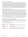
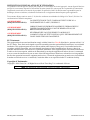
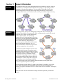
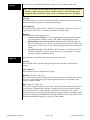
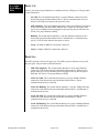
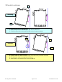
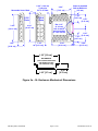
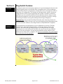
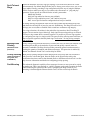
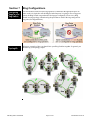
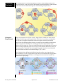
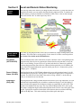
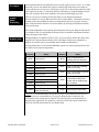
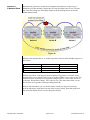
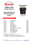
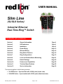
USER MANUAL Slim Line (SL/SLX Series) Industrial Ethernet Real-Time-Ring™ Switch Contents at a Glance: Section 1 General Information Page 4 Section 2 LED Indicators Page 6 Section 3 Installation Page 9 Section 4 Power Wiring Page 13 Section 5 Ethernet Wiring Page 14 Section 6 Ring Switch Features Page 16 Section 7 Ring Configurations Page 19 Section 8 Local and Remote Status Monitoring Page 21 Section 9 Default Settings Page 25 Section 10 Features and Capabilities Page 26 Section 11 Technical Specifications Page 28 Section 12 Service Information Page 30 This manual applies to the following products: SL-6RS Series – 6 port models with 10/100 ports (Lexan case) SLX-6RS Series – 6 port models with 10/100 ports (Aluminum case) 6RS Ring Switch User Manual Page 1 of 30 Last Revised: 25-Feb-14 Red Lion Protected Technology Policy: Red Lion protects your investment in Red Lion systems with long-term planned technology and our unique Protected Technology Policy. We will continue to support the specified capabilities of standard Red Lion products for at least five years. We plan each product improvement and new feature to be upward compatible with existing designs and installations. Our goals are to make each new software release bring new power to your Red Lion systems and have every existing feature, applications program and data file continue to work. We protect your investment even further with a liberal five-year trade-in policy. Exchange standard products for upgraded versions of the same product to take advantage of new features and performance improvements at any time for five years. A prorated trade-in allowance will be given for your existing equipment. Red Lion protects your long-term productivity with state-of-the-art planned technology and continued support. Red Lion Statement of Limited Warranty: Red Lion Controls, manufacturer of Red Lion products, warrants to Buyer that products, except software, manufactured by Red Lion will be free from defects in material and workmanship. Red Lion's obligation under this warranty will be limited to repairing or replacing, at Red Lion's option, the defective parts within one year of the date of installation, or within 18 months of the date of shipment from the point of manufacture, whichever is sooner. Products may be returned by Buyer only after permission has been obtained from Red Lion. Buyer will prepay all freight charges to return any products to the repair facility designated by Red Lion. This limited warranty does not cover losses or damages which occur in shipment to or from Buyer or due to improper installation, maintenance, misuse, neglect or any cause other than ordinary commercial or industrial applications. In particular, Red Lion makes no warranties whatsoever with respect to implied warranties of merchantability or fitness for any particular purpose. All such warranties are hereby expressly disclaimed. No oral or written information or advice given by Red Lion or Red Lion’s representative shall create a warranty or in any way increase the scope of this warranty. This limited warranty is in lieu of all other warranties whether oral or written, expressed or implied. Red Lion's liability shall not exceed the price of the individual units, which are the basis of the claim. In no event shall Red Lion be liable for any loss of profits, loss of use of facilities or equipment, or other indirect, incidental or consequential damages. INSTALLATION AND HAZARDOUS AREA WARNINGS: These products should not be used to replace proper safety interlocking. No software-based device (or any other solidstate device) should ever be designed to be responsible for the maintenance of consequential equipment or personnel safety. In particular, Red Lion disclaims any responsibility for damages, either direct or consequential, that result from the use of this equipment in any application. All power, input and output (I/O) wiring must be in accordance with Class I, Division 2 wiring methods and in accordance with the authority having jurisdiction. WARNING (EXPLOSION HAZARD) - SUBSTITUTION OF COMPONENTS MAY IMPAIR SUITABILITY FOR CLASS 1, DIVISION 2. WARNING (EXPLOSION HAZARD) - WHEN IN HAZARDOUS LOCATIONS, DISCONNECT POWER BEFORE REPLACING OR WIRING UNITS. WARNING (EXPLOSION HAZARD) - DO NOT DISCONNECT EQUIPMENT UNLESS POWER HAS BEEN SWITCHED OFF OR THE AREA IS KNOWN TO BE NONHAZARDOUS. 6RS Ring Switch User Manual Page 2 of 30 Last Revised: 25-Feb-14 INSTRUCTIONS D’INSTALLATION ET D’UTILISATION: Ces produits ne doivent pas être utilisés pour remplacer le verrouillage de sécurité approprié. Aucun dispositif basé sur un logiciel (ou tout autre dispositif à l'état solide) devraient jamais être conçus pour être responsable de l'entretien de l'équipement consécutifs ou la sécurité du personnel. En particulier, Red Lion décline toute responsabilité pour les dommages, directs ou indirects, résultant de l'utilisation de cet équipement dans n'importe quelle application. Tout courant, câblage entrée et sortie (I / O) doit être conforme aux méthodes de câblage à la Classe I, Division 2 et conformément à l'autorité compétente AVERTISSEMENT (RISQUE D’EXPLOSION) AVERTISSEMENT (RISQUE D’EXPLOSION) AVERTISSEMENT (RISQUE D’EXPLOSION) - LA SUBSTITUTION DE TOUT COMPOSANT PEUT NUIRE À LA CONFORMITÉ DE CLASSE I, DIVISION 2. LORSQUE DANS DES ENDROITS DANGEREUX, DÉBRANCHEZ LE CORDON D'ALIMENTATION AVANT DE REMPLACER OU DE BRANCHER LES MODULES. NE DÉBRANCHEZ PAS L'ÉQUIPEMENT À MOINS QUE L'ALIMENTATION AIT ÉTÉ COUPÉE OU QUE L’ENVIRONNEMENT EST CONNU POUR ÊTRE NON DANGEREUX. FCC Statement: This equipment has been tested and found to comply with the limits for a Class B digital device, pursuant to Part 15 of the FCC Rules. These limits are designed to provide reasonable protection against harmful interference in a residential installation. This equipment generates uses and can radiate radio frequency energy and, if not installed and used in accordance with the instructions, may cause harmful interference to radio communications. However, there is no guarantee that interference will not occur in a particular installation. If this equipment does cause harmful interference to radio or television reception, which can be determined by turning the equipment off and on, the user is encouraged to try to correct the interference by one or more of the following measures: Reorient or relocate the receiving antenna; Increase the separation between the equipment and receiver; Connect the equipment into an outlet on a circuit different from that to which the receiver is connected; Consult the dealer or an experienced radio/TV technician for help. Copyright & Trademarks: Copyright 2014 Sixnet, Inc. All Rights Reserved. Real-Time-Ring™ is a trademark of Sixnet. Note: All information in this document is subject to change without notice. 6RS Ring Switch User Manual Page 3 of 30 Last Revised: 25-Feb-14 Section 1 Overview Operation General Information This manual will help you install and maintain the Real-Time-RingTM Switch. The Ring Switch allows you to implement the traditional star topology, or ring topology to take advantage of network path redundancy. The switch can be used right out of the box without configuration; or through some simple configuration steps, some powerful managed switch features can be enabled such as traffic prioritization and port mirroring. In the Ring Switch, messages are intelligently routed for the sake of increasing the efficiency and reliability of your network. Unlike an Ethernet hub, a switch will forward packets to specific ports to reduce unnecessary traffic on network paths, thus optimizing network efficiency. Most importantly, by using a Ring Switch, you can implement redundant paths in a network by allowing ring topology (for a more resilient network). Ring topology is important in path redundancy because no matter where in the ring that a path gets “cut”, all devices connected to a node in the ring will still be able to communicate with each other. Conventional switches and hubs cannot be used in ring topologies because of broadcast storms. Broadcast storms can bring a network to a stop if conventional switches or hubs are being used in a ring topology because of broadcast message reproduction. Using Ring Switches in the loop will prevent broadcast storms because they have the intelligence to detect loops and to assign the necessary ports to be in the backup (disabled) state. These backup ports will be instantly enabled should the primary path in their respective ring fail. See picture to the right: The Ring Switch supports 10BaseT (10 Mbps) and 100BaseT (100 Mbps) on its RJ45 ports. Each of these ports will independently auto-sense the speed, allowing you to interface to regular or fast Ethernet devices. Some models also have 100BaseF (100 Mbps) optic ports. Refer to Section 6 for more information on Ring Switch configuration, operation and features. 6RS Ring Switch User Manual Page 4 of 30 Last Revised: 25-Feb-14 Performance Specifications Standards and Safety These general specifications apply to the Real-Time-RingTM Switch. Refer to Section 11 for complete technical specifications. Ports 6 Port types (varies by model) 10/100BaseT (Shielded RJ45), 100BaseF (SC or ST connectors) Ethernet switch type Intelligent Store and Forward with Real-TimeRing™ plus some management capabilities Ethernet protocols supported All IEEE 802.3 RJ45 operation Auto negotiation, Auto-Crossover and AutoPolarity Fiber operation Multimode or singlemode with distances up to 120 km or more The Ring Switch meets the following standards: Electrical safety - UL 508, CSA C22/142; IEC 61010-1 EMC performance - FCC part 15, ICES 003; EN61000-6-2/4, CE NOTE: To meet full compliance with CE and maritime requirements shielded Etherenet cables must be used. Markings : Direct Current: 10-30 VDC (min./max.) Protective Conductor Terminal Hazardous locations – ISA12.12.01, CSA C22.2/213 (Class 1, Div. 2), Groups A, B, C, D. SL enclosure : ATEX per EN60079-0, -15(Zone2) II 3G, Ex nA IIC T4 X TAMB ≤ 60C SLX enclosure: ATEX per EN60079-0, -15(Zone2) II 3G, Ex nA IIC T4 X TAMB≤85C Install the Real-Time-Ring Switch in accordance with local and national electrical codes. Lightning Danger: Do not work on equipment during periods of lightning activity. Do not connect a telephone line into one of the Ethernet RJ45 connectors. 6RS Ring Switch User Manual Page 5 of 30 Last Revised: 25-Feb-14 Section 2 LED Indicators Overview The Ring Switch has communication LEDs for each port and power LEDs for each input terminal. In addition, two LEDS (OK and Ring) provide switch and network status. Refer to the pictures below for the location of these LEDs. Power LEDs There are two power LEDs on the switch. Both indicate if there is power applied to the respective terminal. 6RS Ring Switch User Manual Page 6 of 30 Last Revised: 25-Feb-14 OK LED The OK LED is a multifunctional indicator, which has several states defined below. Note: The OK LED and OK Output do not always coincide. In general the OK LED will always indicate any type of error condition. However the OK Output can be configured using the Ethernet Switch Tools to only indicate the errors you define. ON solid: The OK LED will be in a steady ON state when both P1 and P2 power inputs are powered and that all configured rings have continuous ring integrity. OFF completely: The OK LED will be OFF if either P1 and/or P2 is not powered, or if any one of the active rings for which this switch is a member of encounters a segment failure. Blinking: The OK LED can blink at different rates. Continuous rapid blinking: To verify communication and target switch selection, you can request the switch to “wink” its OK LED to visually identify the unit. Rapid blinking, with a single short pause: Should the OK LED blink rapidly for about 5 sec and then pause for about 1 second, this indicates that the switch is in the boot-up process such as on power-up, when loading firmware or when resetting the switch. Long OFF, short ON: If the OK LED is OFF for about 1.9 seconds and ON for .1 seconds, an internal error has occurred in the unit. Try cycling power or resetting the switch from the configuration utility. Ring LED The Ring LED is a multifunctional indicator that shows four states. ON solid: The Ring LED will be ON when all rings enabled in the switch have continuous ring integrity. OFF completely: The switch has not been configured for any rings. Blinking: (50% OFF – 50% ON) One or more rings have been configured for the switch, but a break has been discovered for one or more of the configured rings. Neighboring Ring Switches are responding, so the break is at another location. Blip: (Long OFF – Short ON) One or more configured rings have been broken. The break has been detected to be local to one of the ports. Diagnostically speaking; in simple rings, the segment with the problem will be between the two switches with their ring LEDs in the blip state. Also, you can ascertain the general location of where the segment error has occurred with a HMI, a master controller, or some other MODBUS Master through MODBUS/UDP polling. Find out more details about MODBUS diagnostics in section 8 of this manual. 6RS Ring Switch User Manual Page 7 of 30 Last Revised: 25-Feb-14 ACT / LNK/ 10/100 Mbps LEDs Ports 1-4: Activity, link, and port speed indication is combined into one LED per port. The port states are described below: - ON solid: This would indicate that there is a proper Ethernet connection (Link) between the port and another Ethernet device, but no communications activity is detected. The LED color indicates the speed see below. - OFF completely: This would indicate that there is not a proper Ethernet connection (Link) between the port and another Ethernet device. Make sure the proper cable type is in use and that it has been plugged securely into the ports at both ends. See section 5 for proper Ethernet cabling. - Blinking: This would indicate that there is a proper Ethernet connection (Link) between the port and another Ethernet device, and that there is communications activity. The LED color indicates the speed see below. - Green: 100 Mbps (100BaseT) connection is detected. - Yellow: 10 Mbps (10BaseT) connection is detected. Ports 5-6: The RJ45 connector version (all copper) use Two LED per port to indicate Activity, link, and port speed. The port states are described below: 6RS Ring Switch User Manual - LED OFF completely: This would indicate that there is not a proper Ethernet connection (Link) between the port and another Ethernet device. Make sure the proper cable type is in use and that it has been plugged securely into the ports at both ends. See section 5 for proper Ethernet cabling. - Yellow ON solid: This would indicate that there is a proper 10Mbps Ethernet connection (Link) between the port and another Ethernet device, but no communications activity is detected. - Yellow ON Blinking: This would indicate that there is a proper 10Mbps Ethernet connection (Link) between the port and another Ethernet device, and that there is communications activity. - Green ON solid: This would indicate that there is a proper 100Mbps Ethernet connection (Link) between the port and another Ethernet device, but no communications activity is detected. - Green ON Blinking: This would indicate that there is a proper 100Mbps Ethernet connection (Link) between the port and another Ethernet device, and that there is communications activity. Page 8 of 30 Last Revised: 25-Feb-14 Section 3 Overview Installation The Ring Switch can be mounted onto a standard DIN rail (EN50022) or screwed directly to a flat panel. Refer to the mechanical drawings below. Make sure to allow enough room to route your Ethernet cables. SL model in Lexan case: 1 Mounting 2 Recommended DIN rail mounting steps: 1. Hook the top back of the unit over the DIN rail. 2. Push the bottom of the unit towards the DIN rail until it snaps into place. Removal B A Recommended DIN rail removal steps: A. Insert screwdriver into DIN clip and pry until the bottom of the unit releases from the din rail. B. Unhook the top of the unit and remove it from the DIN rail. 6RS Ring Switch User Manual Page 9 of 30 Last Revised: 25-Feb-14 SLX model in metal case: 1 Mounting 2 Recommended DIN rail mounting steps: 1. Hook the top back of the DIN rail clip on the unit over the din rail. 2. Push the bottom of the unit towards the DIN rail until it snaps into place. A C Removal B Recommended DIN rail removal steps: A. Push the whole unit down to free the bottom of the DIN rail clip. See blue circle area. B. Pull the bottom of the unit away from the DIN rail. C. Unhook the top of unit and remove it from the DIN rail. 6RS Ring Switch User Manual Page 10 of 30 Last Revised: 25-Feb-14 Removable Screw Block 2/3/5 Ports 0.40" (1.02 cm) Typical for SC or ST fiber 2.90" [7.35 cm] 1.01" [2.57 cm] 6/8/9 Ports 1.98" [5.02 cm] Dia. 0.15" (0.38 cm) Use for direct panel mounting to a flat surface 4.20" [10.67 cm] 3.95" [10.03 cm] Snaps to standard DIN rail EN50022 (35 mm) 1.98" [5.02 cm] 1.01" [2.57 cm] 3.26" [8.28 cm] 1.50" [3.81 cm] 1.00" [2.54 cm] 0.06" [0.15 cm] 1.38" [3.5 cm] DIN EN50022 (not included with units; not shown to scale; for reference only) 1.06" [2.7 cm] 0.30" [0.76 cm] Figure 3a – SL Enclosure Mechanical Dimensions 6RS Ring Switch User Manual Page 11 of 30 Last Revised: 25-Feb-14 SLX 0.175" [0.44 cm] 2/3/5 Ports 4.50" [11.43 cm] 0.40" (1.02 cm) Typical for SC or ST fiber 6/8/9 Ports 4.00" [10.16 cm] 4.35" [11.05 cm] Snaps to standard DIN rail EN50022 (35 mm) 0.30" [0.76 cm] Use for direct panel mounting to a flat surface with up to #8 screw for older units or up to #12 for newer units (see guide to right) 2.25" [5.71 cm] C Removable for direct panel mounting 0.55" [1.40 cm] 1.50" [3.81 cm] 3.00" [7.62 cm] 0.80" [2.03 cm] 1.60" [4.06 cm] 1.10" [2.79 cm] Panel mounting ears on newer models accept up to a #12 screw Removable Screw Block 2.25" [5.71 cm] 0.39" [0.99 cm] Direct to panel mounting guide 1.38" [3.5 cm] DIN EN50022 (not included with units; not shown to scale; for reference only) 1.06" [2.7 cm] 0.30" [0.76 cm] Figure 3b – SLX Enclosure Mechanical Dimensions 6RS Ring Switch User Manual Page 12 of 30 Last Revised: 25-Feb-14 Section 4 Power Wiring These Ring switches can be powered from the same DC source that is used to power your other devices. A voltage in the range of 10 to 30 VDC needs to be applied between the P1 (plus) terminal and the Minus terminal as shown in the diagrams. To reduce down time resulting from power loss, these industrial Ethernet switches can optionally be powered redundantly with a second power supply as shown in the diagrams. Overview The managed models also have an “OK” output that can be tied to a PLC input or other device to indicate when there is a power loss. When ON, this output will source the same voltage that is applied to the switches power terminals. See the wiring diagrams. WIRING WARNINGS BEFORE PERFORMING ANY WIRING TO THESE SWITCHES MAKE SURE … THE AREA IS CURRENTLY NONHAZARDOUS (ESPECIALLY WHEN WORKING IN CLASS I, DIV 2 OR ZONE 2 HAZARDOUS LOCATIONS) TO TURN OFF THE POWER TO THE SWITCH TO UNPLUG THE SCREW TERMINAL BLOCK (This is especially important on the units that have a metal case as shown below. Connecting or disconnecting wires to the screw block when it is in place and the power is turned on can allow the screwdriver to short the power to the case.) When tightening the screws be careful to tighten to a max. torque of 5 in/lb (0.57 Nm). Wiring Diagram Single DC Supply + Front of Switch (connectors) P2 P1 OK Dual DC Supplies Alarm Output Load (opt.) + - Screw Torque Chassis GND is made through the DIN rail mounting P2 P1 OK Alarm Output Load (opt.) Back of Switch (DIN rail) Single DC Power Redundant DC Power Figure 4a – Power & Alarm Wiring Diagram 6RS Ring Switch User Manual Page 13 of 30 Last Revised: 25-Feb-14 Section 5 Ethernet Wiring Overview The Ring Switch provides Ethernet and fiber connections to devices on the factory floor through star or ring topology. When wiring the Ring Switch in a ring topology, it is important that only Ring Switches are used for each node in the ring. With proper ring wiring, all nodes in the ring can maintain the same data connectivity should a path in the ring be “cut”. Be sure to visit Section 7 for detailed examples about valid and invalid ring topologies. RJ45 Wiring Guidelines Use data-quality (not voice-quality) twisted pair cable rated category 5 or better with standard RJ45 connectors. To meet full compliance with CE and maritime requirements, shielded Ethernet cables must be used. Straight through or crossover category 5 cable can be used regardless of the type of device connected to the Ring Switch. This is because the Ring Switch supports auto-mdi/mdix-crossover. Ethernet Cable Pin-outs (for reference only) Straight-thru Cable Wiring Pin 1 Pin 1 Pin 2 Pin 2 Pin 3 Pin 3 Pin 6 Pin 6 Ethernet Connector Pin Positions Ethernet Fiber Wiring Guidelines Cross-over Cable Wiring Pin 1 Pin 3 Pin 2 Pin 6 Pin 3 Pin 1 Pin 6 Pin 2 Cable Distance The maximum cable length for 10/100/1000 BaseT is typically 100 meters (328 ft.). The Ring Switch optionally has one or two pair of multimode or singlemode fiber ports. The maximum segment length is up to 120+ km depending on the type of fiber optic transceiver installed in the switch. Refer to the technical specifications for details. Each fiber optic port on the switch is comprised of a pair of SC or ST style connectors. For each fiber port there is a transmit (TX) and receive (RX) signal. When making your fiber optic connections, make sure that the transmit (TX) port of the switch connects to the receive (RX) port of the other device, and the receive (RX) port of the switch connects to the transmit (TX) port of the other device. See the image below for the location of the fiber ports. The ACT/LNK LED will be ON solid when you have made a proper connection. 6RS Ring Switch User Manual Page 14 of 30 Last Revised: 25-Feb-14 Duplex Operation The RJ45 ports will auto-sense for Full or Half duplex operation, while the fiber ports are configured for full duplex operation. Note: Fiber devices with half duplex settings should still communicate with the switch. If otherwise then contact your switch vendor. Network Device Check The Ring Switch is capable of supporting 10/100BaseT and 100BaseF. Make sure you connect the appropriate devices to each port. 6RS Ring Switch User Manual Page 15 of 30 Last Revised: 25-Feb-14 Section 6 Overview Ring Switch Features The Ring Switch has all the networking capability of a typical unmanaged switch plus some advanced capability that you would only find in a managed switch. Like an unmanaged switch, the Ring Switch is “plug and play” meaning that it can be used right out of the box without any user configuration. This includes the ring functionality, which is already preconfigured in the switch. For most applications this is all that is needed. For advanced applications you can use the Ethernet Switch Tools (Windows software utility) to enable some advanced capabilities such as priority queuing for prioritizing your traffic, message rate filtering for broadcast storm protection and port mirroring for diagnostics. Important Note: Only use Real-Time-Ring™ Switches when connecting switches in a ring. The Real-Time-Ring™ Switches use a specialized high-speed ring algorithm that only they will understand. Otherwise, these Ring Switches are fully IEEE 802.3 compatible. Ring Setup & Operation For ring operation in most applications, no user configuration is necessary. The Ring Switches can be ordered pre-configured with 1 or more pairs of ports setup for ring operation. Just connect the ring-configured ports of your Ring Switches in a ring by connecting the last switch back to the first. Make sure you use only the ring configured ports for your ring connections. The non-ring ports should be used to connect to your Ethernet devices such as PLCs, computers, etc. Be sure to visit Section 7 for great examples about valid and invalid ring topologies. 6RS Ring Switch User Manual Page 16 of 30 Last Revised: 25-Feb-14 Ring Algorithm and Performance The Real-Time-Ring™ feature utilizes a special algorithm that assures very fast recovery times. Each Real-Time-Ring switch utilizes the special high-speed algorithm to keep track of the health of the ring. In a healthy ring (a complete ring), one ring switch will be automatically picked to act as a master (switch with lowest MAC address) for the ring network. Alternatively, you can designate one of your ring switches to be the master using the Ethernet Switch Tools. It is the master switch’s job to determine which one of its local ring ports are to be in the forwarding or backup state. The ring port chosen to be in the backup state is where the backup segment of the ring will be. By default, the ring port with the higher port number will become the backup port. All ring switches in the ring must have a way to keep track of each other in case a failure in communication occurs along the ring. To keep track of the health of the ring, the Ring switches periodically send test messages to each other. Therefore, when a ring gets “cut” at a certain location, the Ring switches will know and they will take the appropriate action to bring the network back online. The time that it takes for the last Ring switch to “know” and take appropriate action to rectify the communication problem will be when the link loss “recovers”. Recovery time can be estimated by multiplying 5 mS times the number of switches, and then adding 30 mS (for loss of link errors) or 60 mS (for message loss errors). For example, a ring of 10 switches would have a recovery time of 80 mS for the typical loss of link type errors. Master Switch Selection As mentioned above, the ring switch with the lowest MAC address will automatically become the master and block one of its ports (highest number port). Alternatively, you can designate one of your ring switches to be the master using the Ethernet Switch Tools. There is a simple check box where you can select “Automatic” or “This Switch” for the master ring switch selection. This advanced capability allows you to control where the backup port will be in your network. It is recommended that only one ring switch be designated as the master. If more than one is designated as the master then the one with the lowest MAC address will prevail. Ethernet Switch Tools In some applications it may be desirable or required to adjust the Ring Switches parameters for proper or best operation. A Microsoft Windows software utility called the Ethernet Switch Tools is provided to make these adjustments. By using the “auto-find” feature in the utility, you will be able to pick from a list of detected Ring Switches and load custom configurations via Ethernet. The auto-find feature eliminates the hassle of loading via a serial connection and the overhead time spent assigning IP addresses. Refer to the online help for details on using the Ethernet Switch Tools. Hot Tip: Refer to the Ethernet Switch Tool’s comprehensive on-line help for more details. Port Configuration IMPORTANT NOTE: Your computer must be on the same local network as the Ring Switch for the Ethernet Switch Tools to operate properly. Also, your computer must have updated Raw Ethernet Socket (WinPcap) support installed. When installing the Ethernet Switch Tools, the installation program will call the WinPcap installation program if necessary. If you have an older version of WinPcap installed, the installation program will prompt you to remove the older version before continuing with the installation. Ring Switches auto-negotiate port settings. In most applications port settings are best left in the default "Auto" connection mode. For special situations, the ports can be "Fixed" to restrict communications to only 10 or 100 Megabits per second, with either half or full duplex. Flow control can be enabled or disabled as well. Port configuration settings are adjustable using the Ethernet Switch Tools. 6RS Ring Switch User Manual Page 17 of 30 Last Revised: 25-Feb-14 Fault Tolerant Rings A network backbone wired in a ring type topology is one of the best choices for a faulttolerant network. By default, Ring Switches may be factory preset to have zero, one, or two rings enabled. Factory presetting a ring configuration skips the step of using the Ethernet Switch Tools to enable your rings so you can have the convenience of “plug and play” operation. Factory presets are indicated in the switch’s part number: -D0 Rings disabled -D1 One ring enabled on last two ports (default) -D2 Two rings enabled on ports 1 and 2 and last two ports -DC A user specified custom configuration has been pre-installed To change the ring configuration in the switch, simply launch the Ethernet Switch Tools and choose the desired pair of ports for your new enabled ring. The Ring LED will be lit if all rings (one or two) that are enabled in this switch have continuous ring integrity. For a ring to function, all switches in the path of the ring must have Real-Time-Ring™ support. Do not connect rings within rings. Only simple non-overlapped rings are allowed. Two active rings cannot share a network segment. It is possible to join two rings together by configuring two rings in a single switch. The ports used for each ring must be distinct, so that no network segment is shared by both rings. See Section 7 for ring wiring examples and guidelines. Message Rate Filtering (Broadcast storm protection) Poorly configured applications and devices or malicious users can flood your network with broadcast packets that are forwarded to all ports and can quickly consume most of a network’s bandwidth. The Ring Switch provides protection against broadcast storms by limiting the quantity of broadcast and multicast messages. This protection is enabled by default. See Ethernet Switch Tool’s on-line help for details. Priority Queuing With priority queuing configured in the Ring Switch, low priority data will not interfere (Traffic Prioritization using QoS, CoS, ToS/DiffServ) with your time critical data again. Network traffic can be prioritized to achieve the performance that time-sensitive data demands. Refer to the Ethernet Switch Tool’s on-line help for more information and details on configuring priority queuing. Port Mirroring This advanced diagnostic capability allows messages from one or more ports to be copied to another port. Then a port analyzer or “sniffer” program can be used to monitor the traffic without affecting the operation of the switch. Configuring the Ring Switch for port mirroring is done through the Ethernet Switch Tools. See the on-line help for details. 6RS Ring Switch User Manual Page 18 of 30 Last Revised: 25-Feb-14 Section 7 Ring Configurations Configuring Rings in your Ring Switch First and foremost, make sure that ring operation is enabled for the appropriate ports. In other words it is required to tell the Ring Switch what ports it is going to use as ring ports (unless the Ring Switch was purchased with rings pre-configured). Never wire a Ring Switch in a ring topology without having the ports that are used in the ring configured as ring ports (See diagram below). Valid Ring Topologies Below are examples of how you should wire your Ring Switches together. In general, you should keep your topology simple. 6RS Ring Switch User Manual Page 19 of 30 Last Revised: 25-Feb-14 Invalid Ring Topologies Unintended Rings Example The examples below are invalid ring topologies. Do NOT connect Ring Switches in the ways shown below, as they will lead to unpredictable network performance. Paths indicated by the color red create unintended rings (see unintended rings example below). Refer to the diagram below. In this example, Ring Switches A and B have been software configured for two rings each. Ring Switches C and D have been software configured for one ring each. The physical connections for the two rings are shown in blue and red. Since the rule for configuring Ring Switches is to make sure that each Ring Switch knows about all rings that are attached to it, it would appear that the example below is legal. However, this is not the case. There are actually more than two ring paths that were created. There are multiple paths that traffic can use to move from Switch A and back to Switch A. The same applies to Switch B. These unintended Ring paths that Switch A and Switch B don’t know about are labeled as Unintended Rings A, B, C, and D. Since Ring Switch A and Ring Switch B don’t know about these extra ring paths, they aren’t included in A or B’s ring algorithm. Paths that are not included in the ring algorithm will result in harmful broadcast storms, as will happen when conventional switches are connected in a ring topology. A C D B 6RS Ring Switch User Manual Page 20 of 30 Last Revised: 25-Feb-14 Section 8 Local and Remote Status Monitoring Switch Status You can keep track of the status of your Ring Switches at all times. To check the status of a Ring Switch visually, you can monitor the Ring Switch’s indicator LEDs. To monitor the status remotely, you can use Modbus over Ethernet (UDP). There is also an alarm output that can be tied to a PLC or other supervisory device. Visual Status Monitoring The status of your Ring Switches can be easily ascertained by simply looking at their LED indicators. The LEDs can be used to quickly see the status or to locate a network problem. See Section 2 for details on the LED indicators. Port Status (ACT/LNK LED) After all Ethernet and/or fiber connections are made, check the LED’s corresponding to the ports that each of the devices are connected to. Ensure that for each port that is in use, the LED is on or blinking. If a port LED is off, go back and check for connectivity problems between that port and the network device connected to that particular port. In addition, the color of the LED should indicate the speed for which your device is connected at (yellow – 10Mbps, green – 100Mpbs). Power & Switch Status (OK LED) The Ring Switch has an OK LED that indicates the power and operational status. It is ON solid when there are no errors. It will go OFF if either power supply fails or a ring break is detected. The OK LED will also flash if the switch is being “winked”, is in the boot-up mode, or an internal error was detected. Ring Status (Ring LED) The Ring Switch has a Ring LED that indicates the status of your ring connections. It is ON solid when all rings handled by the switch have continuous integrity. It will be blinking if there is broken ring segment but all adjacent switches are responding. It will be OFF if the switch is not configured for any rings. The ring LED will Blip (mostly OFF, with a quick ON) when a configured ring has been broken and the break is local to one of the ports of the switch. Typically the network with the fault will be between the two switches with Ring LEDs in the Blip state. This makes tracking down faults quick and simple. 6RS Ring Switch User Manual Page 21 of 30 Last Revised: 25-Feb-14 OK Output The Ring Switch has an OK Output that can be used to signal an error to a PLC, PC or other supervisory devices. By default, this output is normally ON when both power inputs are present and there are no ring errors. The output will go OFF if either power input fails, both power inputs fail or there is a ring break detected. Alternatively, using the Ethernet Switch Tools you can define which error conditions will cause the OK Output to go OFF. Remote Status Monitoring There are two ways to remotely monitor the status of your Ring Switch network. The first method is to use the Ethernet Switch Tool’s status display. This display will show the status of the selected Ring Switch by providing details such as port, power, and ring states. Find more details about how to use this display by referring to the Ethernet Switch Tool’s on-line help. The second method that can be used for determining the state of your Ring Switch network is via Modbus UDP. See the Modbus UDP topic below for detailed information about how to take advantage of this feature. Modbus/ UDP Through Modbus over Ethernet (UDP or TCP), you can remotely monitor the status of the Ring Switch. Using the Ethernet Switch Tools, the Ring Switch can be configured as a Modbus slave station with its own Modbus station number and IP address. The Ring Switch has a set of predefined Modbus registers for status reporting. Refer to the table below for the register assignments. Modbus Address Modbus Address Status Status 10001 Link on port 1 10019 Ring 1: Second port is passing data (not blocked) 10002 Link on port 2 10020 Ring 2 complete 10003 Link on port 3 10004 Link on port 4 10021 Ring 2: First port is passing data (not blocked) 10005 Link on port 5 10006 Link on port 6 10022 Ring 2 second port is passing data (not blocked) 10007 Link on port 7 10008 Link on port 8 10030 10009 Link on port 9 OK output ON (no alarms) Output will be ON if both power and all enabled rings are complete. 10017 Ring 1 complete 10031 First power input valid 10018 Ring 1: First port is passing data (not blocked) 10032 Second power input valid NOTE: It is recommended that you keep the poll time of your Modbus master driver or hardware device to a reasonable rate. If you poll a Ring Switch at a rapid rate, the performance of the switch may be reduced. The fastest poll time you should run will depend on the application. As a guideline, a poll time of 500 mS or greater should not adversely affect the performance of your Ring Switch. 6RS Ring Switch User Manual Page 22 of 30 Last Revised: 25-Feb-14 Modbus Diagnostics Example As an example of how to debug a network using the Modbus registers, we will examine a simple ring topology, which is shown in the figures that follow. Scenario 1: No Breaks Taking a look at the diagram below, we see three Ring Switches. Ring Switches A, B, and C have been configured for one ring. The ring network is currently in good health (no breaks in the ring) with the solid blue line indicating the active part of the ring, and the dashed blue line indicating the standby part of the ring. Switch A Switch B Switch C Figure 6a Since the ring network is in good health, we would expect these values from the Modbus registers of each switch: Switch A Ring 1 Complete: 1 First Port of Ring 1: 1 Second Port of Ring 1: 1 Switch B Ring 1 Complete: 1 First Port of Ring 1: 1 Second Port of Ring 1: 1 Switch C Ring 1 Complete: 1 First Port of Ring 1: 0 Second Port of Ring 1: 1 A ring network in good health would have the Ring Complete bit set to one in all Ring Switches. Also, all ports in the ring should be forwarding except for one port that should be in backup mode. The backup port will indicate the standby/backup path of the existing ring. 6RS Ring Switch User Manual Page 23 of 30 Last Revised: 25-Feb-14 Scenario 2: A Network Break Should the ring experience a break like the diagram indicated below (Figure 6b), we immediately see that the Ring Complete bits for each switch have gone to zero. The port that was in the backup state will rapidly change to the forwarding state to activate the standby Ethernet path. Switch A Switch B Switch C Figure 6b With the break indicated above, we would expect these values from the Modbus registers of each switch: Switch A Ring 1 Complete : 0 First Port of Ring 1 : 1 Second Port of Ring 1 : 0 Switch B Ring 1 Complete : 0 First Port of Ring 1 : 0 Second Port of Ring 1 : 1 Switch C Ring 1 Complete : 0 First Port of Ring 1 : 1 Second Port of Ring 1 : 1 With the ring broken, each ring port reports whether its ring partner is available. In the example above, we see that for switch A, the ‘First Port of Ring 1’ has a value of one. This means that switch A can talk to its ring partner (Ring Switch C). For the same switch, we see that the ‘Second Port of Ring 1’ has a value of zero. This means that switch A is not able to talk to its ring partner for that port (Ring Switch B). Based on this information, you can localize where a break in a ring has occurred by checking which ports report back with zero when a ring is broken. Ports that report back with zero mean that the break is local to that particular port. 6RS Ring Switch User Manual Page 24 of 30 Last Revised: 25-Feb-14 Section 9 Default Settings About Default Settings The settings below are the factory defaults when the switch comes out of the box. Use this page to find out what changes may be necessary for tailoring the switch to your exact needs. Ring Ports -D0: No ring(s) configured -D1: Ring 1 configured on last two ports (standard model) -D2: Ring 1 configured on last two ports and Ring 2 configured on Ports 1,2 -EC: Custom configuration as you specified. Master switch selection: Automatic Port Configuration (all ports): Port # Broadcast Limit Enabled on all ports Port Mirroring Mirroring: Disabled Priority Queuing Use 802.1p Tag Priority: Enabled Use IP ToS/DiffServ: Enabled Priority Precedence: Tag Default Priority: Normal Output Tag: Unchanged IEEE Tagging OK Output Name Port_1 Priority 0 1 2 3 4 5 6 7 Admin Negotiation Speed & Duplex Enabled Auto 10h 10f 100h 100f Traffic Type Best Effort Background Spare Excellent Effort Controlled Load Video Voice Network control Flow Control Disabled Queue 0 0 0 1 1 1 1 3 The OK Output will be normally ON and go OFF when either power input is not present, both power inputs are not present or a ring failure is detected. 6RS Ring Switch User Manual Page 25 of 30 Last Revised: 25-Feb-14 Section 10 General Features and Capabilities Features & Capabilities This section explains the primary Ethernet and fiber capabilities of the Ring Switch. 10BaseT and 100BaseT Auto-detection Standard Ethernet (10BaseT) has a maximum speed of 10 Mbps (half duplex mode) or 20 Mbps (full duplex mode). Fast Ethernet (100BaseT) has a maximum speed of 100 Mbps (half duplex mode) or 200 Mbps (full duplex mode). The 10/100 RJ45 ports automatically support both speeds. 100BaseF (multimode and singlemode) fiber optic port The fiber optic port found on some models is classified as 100BaseF and supports 100 Mbps operation. Both multimode and singlemode models are available. Multimode allows for multiple wavelengths over a cable with a core diameter of typically 50 or 62.5 microns. The maximum distance for multimode is up to 4 km. Singlemode uses a single wavelength and cable core diameter of around 9 microns, which allows for a maximum distance of 70 km (long haul models) or more (contact your switch vendor for longer distances). 2K or 8K MAC addresses with automatic learning, aging and migration Each Ethernet device inserts its unique “MAC” address into each message it sends out. The port on the switch used for a given MAC address is automatically learned when a frame is received from that address. Once an address is learned, the switch will route messages to only the appropriate port, instead of broadcasting messages out all ports like a hub. A time stamp is also placed in memory when a new address is learned. This time stamp is used with the aging feature, which will remove unused MAC addresses from the table after 300 seconds. If a device moves, the associated port on the switch will be changed (migrated) as needed. Up to 8,192 MAC addresses can be stored and monitored at any time. 3.2 Gbps combined bandwidth The switches have 3.2 Gbps combined bandwidth. This means that they can support full duplex communications on all ports at the same time. Auto-crossover (auto-mdi/mdix) The RJ45 ports of the Ring Switch will automatically detect the cable type (straight-thru vs. cross-wired) and re-configure themselves accordingly. Auto-polarity The auto-polarity feature corrects reversed polarity on the transmit and receive twisted pair. Automatic power saving If there is no cable on a port, most of the circuitry for that port is disabled to save power. Auto-sensing speed and flow control The RJ45 ports of the Ring Switch will auto-negotiate with the connected device to determine the optimal speed and flow control for each port. Back pressure for half-duplex The Ring Switch will apply “back pressure” when necessary with half-duplex operation. This “back pressure” will reduce congestion on busy networks. Broadcast storm protection Each port can be configured to filter out undesirable broadcast and multicast messages. Buffering SRAM is used for buffering the messages. The Ring Switches have 1 Mbits (128 Kbytes). The buffer size is automatically allocated for each port as necessary. Flow control 6RS Ring Switch User Manual Page 26 of 30 Last Revised: 25-Feb-14 These switches automatically support flow control frames on both the transmit and receive sides. Back-pressure flow control for half-duplex ports and pause-frame flow control for full-duplex ports. Forwarding These switches support store and forward mode. They will forward messages with known addresses out only the appropriate port. Messages with unknown addresses, broadcast messages, and multicast messages will get forwarded out all ports except the source port. Full / Half duplex operation The RJ45 ports of these switches support both full and half duplex operation. The fiber optic port(s) are full duplex but can be interfaced to device with half or full duplex. Illegal frames Illegal frames as defined by IEEE 802.3 will be dropped. This includes short frames, long frames, CRC error frames and alignment error frames. IEEE 802.3 compliant Real-Time-Ring™ Switches strictly abide to the IEEE 802.3 standard for 10BaseT, 100BaseT and 100BaseF Ethernet communications. Latency The typical latency of a message is 5 microseconds (@ 100 Mbps) plus the frame time. The latency is the time it takes a message to be routed internal to a switch from one port to another. This time is highly dependent on the amount of network activity, the speed and the features enabled in the switch. Non-blocking This means that the switches offer the best in performance and are capable of full-wire speed transmissions. Port Mirroring Powerful diagnostic mode that lets you map messages between ports. Plug and play This means that most functions or features of these switches are automatic and that there are minimal or no optional parameters that need to be set. Just plug in your Ethernet cables, apply power, and the unit will immediately begin to operate. The Ring Switches can even be factory pre-configured to your exact needs. Priority queuing or Traffic Prioritization The Ring Switches support QoS (Quality of Service), CoS (Class of Service), ToS (Type of Service), and DS (Differentiated Services) mechanism for ensuring the priority traffic is handled properly. These advanced parameters can be set via the configuration utility. Protocol independent These switches will work with all popular Ethernet protocols and networks such as TCP/IP, the Internet (IP), UDP, NetBEUI, and many more. It is compatible with all protocols that run over standard Ethernet (IEEE 802.3). In fact, it will support packets of different protocols simultaneously. 6RS Ring Switch User Manual Page 27 of 30 Last Revised: 25-Feb-14 Section 11 Technical Specifications Technical Specifications Here are the technical specifications for the Real-Time-Ring™ Switch. Copper RJ45 Ports: (10/100BaseT) Connectors Shielded RJ45 Protocols supported All standard IEEE 802.3 Ethernet compliancy IEEE 802.3, 802.3u, 802.3x, 802.3z, 802.1p and more Auto-crossover RJ45 MDI/MDIX (allows you to use straight or cross wired cables) Auto-negotiating 10BaseT, 100BaseT as applicable Auto-sensing Full or half duplex Auto-polarity Yes, on the TD and RD pairs Flow control Yes, for Half or full duplex Half or full duplex Yes, automatic or configurable Ethernet isolation 1500 VRMS 1 minute Plug and play Yes with factory pre-configuration available for special parameters Cable requirements Twisted pair (Cat. 5 or better) (shielded recommended) Max. cable distance 100 meters SC or ST Fiber Ports: (100BaseF multimode or singlemode) 100BaseFX ports 2 Fiber port mode Multimode (mm) or Singlemode (sm) Fiber port connector Duplex SC or ST Optimal fiber cable 62.5/125 µm for mm; 9/125 µm for sm Center wavelength 1300 nm TX output power Contact Red Lion or see fiber datasheet RX input sensitivity Contact Red Lion or see fiber datasheet Max. distance (full duplex) 4 km with mm; 20 km with sm, 120+ km with long haul sm Half and full duplex Software Configurable Ethernet compliance 100BaseFX Eye safety IEC 60825-1, Class 1; FDA 21 CFR 1040.10 and 1040.11 Note: Additional fiber optic transceiver specifications are available. Also, other fiber transceivers may be available for special requirements such as longer distances, single strand or other special applications. Contact Red Lion for details. 6RS Ring Switch User Manual Page 28 of 30 Last Revised: 25-Feb-14 General: Operation Ethernet protocols supported Typical latency for 10 Mbps Typ. latency for 100/1000 Mbps MAC addresses supported Buffer memory Buffer allocation per port Memory bandwidth Address learning Address aging Address migration Back pressure Illegal frames Flow control Traffic prioritization Status Reporting Modbus over Ethernet (UDP) “OK” output voltage “OK” output max. current Real-Time-Ring™ Features Maximum switches in ring Dual ring support Link loss recovery time Environmental Power input Input power (typical with all ports active) Input voltage Transient protection Spike protection Ethernet isolation Operating temperature range Storage temperature range Humidity (non-condensing) Vibration Electrical safety EMC Hazardous locations Marine and off-shore Eye safety (fiber models) Packaging (Lexan or alum. case) Dimensions (L x W x H) 6RS Ring Switch User Manual Intelligent store & forward, non-blocking All IEEE 802.3 16 us + frame time Varies on load & settings 5 us + frame time 2K (10/100 models) or 8K (gigabit models) 1 Mbits (128 Kbytes) Automatic and dynamic 3.2 Gbps (10/100 models) for full-wire speed on all ports Automatic Remove old address after 300s Automatic Automatic for half-duplex Dropped per 802.3 Yes, for half and full duplex 802.1p, QoS, CoS, ToS/DS Power & operational status Modbus status registers Same as switch input voltage 0.5 Amp Fault-tolerant loop support 50+ Yes Less than 30 mS plus 5 mS per hop DIN rail or direct panel mounting Redundant input terminals 3.0 W (without fiber) 4.8 W (with 2 fiber) 10-30 VDC 15,000 watts peak 5,000 watts (10x for 1000 uS) or 250 volts (50x for 100uS) 1500 VRMS 1 minute SL model : -10 to +60 °C SLX model : -40 to +85 °C -40 to +85 °C 5 to 95% RH IEC60068-2-6 UL508/CSA C22, IEC61010-1, CE FCC part 15, ICES-003; EN61000-6-2/4, CE ISA12.12.01, CSA C22.2/213 (Class1, Div. 2), EN60079-15 (Zone 2, category 3, CE (ATEX) Designed for marine and offshore per ABS IEC60825-1, Class 1; FDA 21 CFR 1040.10 and 1040.11 IP30 protection; UL 94V-0 See mechanical diagram Page 29 of 30 Last Revised: 25-Feb-14 Section 12 Service Information Service Information We sincerely hope that you never experience a problem with any Red Lion product. If you do need service, call Red Lion at 1-877-432-9908 for Technical Support. A trained specialist will help you to quickly determine the source of the problem. Many problems are easily resolved with a single phone call. If it is necessary to return a unit to us, an RO (Repair Order) can be obtained on the Red Lion website. Red Lion tracks the flow of returned material with our RO system to ensure speedy service. You must include this RO number on the outside of the box so that your return can be processed immediately. Be sure to have your original purchase order number and date purchased available. We suggest that you give us a repair purchase order number in case the repair is not covered under our warranty. You will not be billed if the repair is covered under warranty. Please supply us with as many details about the problem as you can. The information you supply will be written on the RO form and supplied to the repair department before your unit arrives. This helps us to provide you with the best service, in the fastest manner. Repairs are completed as soon as possible. If you need a quicker turnaround, ship the unit to us by air freight. We give priority service to equipment that arrives by overnight delivery. We apologize for any inconvenience that the need for repair may cause you. We hope that our rapid service meets your needs. If you have any suggestions to help us improve our service, please give us a call. We appreciate your ideas and will respond to them. For Your Convenience: Please fill in the following and keep this manual with your Red Lion system for future reference: P.O. #:__________________ Date Purchased: ___________________ Purchased From:______________________________________________ Product Support To obtain support for Red Lion products: Latest product info: www.redlion.net Phone: 1-877-432-9908 Fax: 1-518-877-8346 E-mail: [email protected] Mailing address: Red Lion Controls, 20 Willow Springs Circle, York, PA 17406 6RS Ring Switch User Manual Page 30 of 30 Last Revised: 25-Feb-14