1
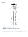
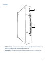
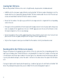
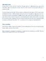
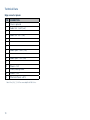
Red 1
500 Series
Mic Pre
User Guide
FA0901-01
www.focusrite.com
2
Dear Focusrite Customer,
Thank you for purchasing the Red 1 500 Series mic pre from Focusrite. First announced in 1993, Focusrite’s Red range
of analogue audio processors rapidly gained legendary status with Red 1 becoming a much sought-after mic pre found
in top recording studios the world over.
Featuring the same circuit topology and components as the original transformer-based mic pre design, Red 1 500
Series offers the same performance as the original Focusrite Red microphone preamplifier in a new popular format,
the 500 Series or “Lunchbox”. Red 1 500 Series features the characteristic red anodised front panel and machined
aluminium gain switch as the original, and, staying true to form, Red 1 500 Series is made in England.
Focusrite would like to encourage you to register your purchase of Red 1 500 Series at www.focusrite.com. Registering
will allow us to inform you of relevant news as well as any new additions to our product range. We would also like to
hear your feedback, so please do contact us through the website.
Yours sincerely,
Focusrite Audio Engineering
Register your product here: http://www.focusrite.com/register
3
RoHS Notice
Focusrite Audio Engineering Limited has conformed and this product conforms, where applicable,
to the European Union’s Directive 2002/95/EC on Restrictions of Hazardous Substances (RoHS)
as well as the following sections of California law which refer to RoHS, namely sections 25214.10,
25214.10.2, and 58012, Health and Safety Code; Section 42475.2, Public Resources Code.
Introduction
This Focusrite Red 1 500 Series is a high quality, single-channel microphone preamplifier in 5.25” x 1.5” modular
format, designed to fit any of the popular “500 Series” portable rack housings.
The Red 1 500 Series is fully analogue, using circuitry identical to that employed in the familiar Focusrite Red 1
fourchannel mic pre, which was itself based on the now-classic ISA designs of the 1980s. The design uses the Lundahl
LL1538 input transformer to provide excellent common-mode rejection and 20 dB of “passive” gain, coupled to a very
low-noise amplifier with Focusrite’s signature extended bandwidth and high overload margin.
The output circuit is also transformer-coupled, which minimises system interconnection problems and provides a fully
balanced source. The circuit can drive very long cable runs – several kilometres if necessary – without significant signal
degradation, making the Red 1 ideal for location recording.
Intended to provide a traditional, analogue “front-end” to any modern digital recording system, the module will give
outstanding audio performance when used with any microphone. You will find it particularly effective for recording
vocals, or acoustic sources such as piano or stringed instruments.
The Red 1 500 Series module’s front panel provides stepped gain selection, switches for 48 V phantom power and
phase, and an illuminated VU meter.
4
Box Contents
•
•
•
•
•
Red 1 500 Series module
2 of #4-40 hex-head fixing screws
3/32” A/F hex key (for fixing screws)
1.5 mm hex key (for gain adjustment knob)
This User Guide
A word about Power
The Red 1 500 Series is supplied with DC power (±16 V and +48 V) by the rack into which it is plugged. The rack’s own
Power Supply Unit (PSU) may be fitted with a power on/off switch. This should be used to apply power to the Red 1 500
Series module (and any other modules in the rack).
Most 500 Series rack power supplies should have sufficient current capability for the rack to be fully-loaded with Red 1
500 Series modules, if wished. However please check the specifications of your chosen 500 Series rack and the current
requirements of Red 1 500 Series at the end of this manual to ensure compatibility. If there is any doubt, please consult
the documentation supplied with the rack.
Note that the Red 1 has no internal fuses.
5
Front Panel
1
5
2
4
3
1
1. Mounting holes – secure the Red 1 500 Series in your rack using the hex-head screws and hex key supplied.
2. GAIN Control – a 12-position switch for setting gain.
3. Polarity/Phase – an illuminated push switch, inverts the polarity of the signal.
4. Phantom Power – an illuminated push switch, provides +48 V phantom power at the input.
5. VU Meter – an illuminated meter with VU scaling, indicates the module’s output signal level. Also see item 6 on
the rear panel.
6
Rear Panel
6
Pin 1
7
Pin 15
6. VU Meter Attenuator – slide switch, inserts a 6 dB pad in the meter feed. When down, the VU Meter scaling is
normal (0 VU = +4 dBu). When up, the VU Meter under-reads by 6 dB.
7. Edge Connector – 15 Pin edge connector, makes all power and audio connections to the 500 Series rack.
7
Installing Red 1 500 Series
While installing the Red 1 500 Series into a rack is straightforward, a few precautions should be observed:
• ALWAYS switch the rack power supply off before inserting the Red 1 500 Series module. Attempting to insert the
module while the rack is powered may damage the Red 1 500 Series module and/or the rack itself. The rack must
also be switched off before the Red 1 500 Series module is removed.
• Ensure that the module is the right way up and that the rear edge connector is aligned with the corresponding
socket in the rack.
• Firmly push on the top and bottom of the front panel until the edge connector clicks into place and the fixing screw
holes are aligned with the tapped holes in the rack. DO NOT apply pressure to the face of the VU meter or other
front panel components as this can cause damage.
• Secure the module into the rack (the supplied mounting screws will be the correct size for most rack units, but
please check the rack user guide) and tighten with the larger of the two supplied hex keys.
• Only turn the rack power on when you are confident that the module is correctly inserted and secured.
Recording with the Red 1 500 Series mic preamp
Plug your microphone into the appropriate input connector on the rack, and connect the corresponding output to the
input of your recording system. The Red 1 500 Series is a mic preamplifier; this means that its output is at line level, and
it should only be connected an input suitable for line level signals. Use a balanced connection wherever possible, but
if you only have unbalanced inputs, connect the cable’s “cold” wire to the cable screen at the output of the 500 Series
rack.
If using a microphone which requires phantom power (e.g. a condenser type), press the +48 V button on the Red 1 500
Series. Only enable phantom power when you are confident that the connected equipment requires it.
8
Adjusting the gain
The gain control is a rotary switch with 12 positions. The lowest position is a 6dB pad and the mic signal will be
attenuated by 6 dB at this setting. Each clockwise step of the control increases the mic pre gain by 6 dB, up to a
maximum of 60 dB.
The nominal output level of the Red 1 500 Series module is +4 dBu when the meter indicates 0 VU. The meter may be
recalibrated so that 0 VU = +10 dBu by setting the slide switch at the rear of the module to its up position. In this case,
the meter will now under-read compared to the down setting; the output signal level will be 6 dB higher for the same
meter indication. Please note that the signal levels and corresponding meter readings referenced here are measured
with sinusoidal test signals. Depending on the source material the peak level of the same signal, as displayed in a DAW
for example, could be significantly different. This is usual behaviour for an average level responding VU meter.
Stereo recording
Red 1 500 Series modules are particularly suitable for stereo recording because of the very accurate gain matching
between modules, and hence stereo channels.
When recording with a matched pair of microphones, or a dedicated stereo microphone, use two Red 1 500 Series
modules and set the gain controls on each to the same position.
9
Technical Data
Edge connector pinout:
PIN
CONNECTION
1
Chassis ground
2
Audio Out: “cold” (–ve)
3
4
Audio Out: “hot” (+ve)
5
6
7
8
Audio Input: “cold” (–ve)
9
10
Audio Input: “hot” (+ve)
11
12
Power: +16 V
13
Power/audio ground
14
Power: –16 V
15
Phantom Power: +48 V
Note: Pins 3, 5, 6, 7, 9 & 11 are unused by Red 1 500 Series.
10
Specifications
Maximum Output
+25.5dBu (20Hz–20kHz)
Maximum Input
>+28dBu (200Hz–13kHz), >26dBu (160Hz–20kHz)
Frequency Response Deviation at 30dB gain (20Hz–20kHz) ±0.1dB
Bandwidth (–3dB) at 30dB gain
103 kHz
Range at 60dB gain (–0.5dB)
125Hz–24kHz
Bandwidth (–3dB) at 60dB gain
32Hz–75kHz
Output Noise
–104.5dBu CCIR-RMS
–107dBu A-wgt
EIN
–124.5dBu CCIR-RMS
–128dBu A-wgt
Harmonic Distortion
Third Harmonic
(30dB gain, –30dBu input) Second Harmonic
THD+N (20 kHz bandwidth)
CMRR (24dB gain, –4dBu input, 1kHz)
–101dB (0.0009%)
–88.5dB (0.0038%)
–88dB (0.0039%)
Common mode test: 102dB
IEC 60268-3:2000 test: 89dB
Troubleshooting
For all troubleshooting queries, please visit the Focusrite Answerbase at www.focusrite.com/answerbase where you
will find articles covering numerous troubleshooting examples.
Copyright and Legal Notices
Focusrite is a registered trade mark and Red 1 is a trade mark of Focusrite Audio Engineering Limited.
All other trade marks and trade names are the property of their respective owners.
2013 © Focusrite Audio Engineering Limited. All rights reserved.
11
Warranty and Service
All Focusrite products are built to the highest standards and should provide reliable performance for many years,
subject to reasonable care, use, transportation and storage.
Very many of the products returned under warranty are found not to exhibit any fault at all. To avoid unnecessary
inconvenience to you in terms of returning the product please contact Focusrite support.
In the event of a Manufacturing Defect becoming evident in a product within 12 months from the date of the original
purchase Focusrite will ensure that the product is repaired or replaced free of charge.
A Manufacturing Defect is defined as a defect in the performance of the product as described and published by Focusrite.
A Manufacturing Defect does not include damage caused by post-purchase transportation, storage or careless handling,
nor damage caused by misuse.
Whilst this warranty is provided by Focusrite the warranty obligations are fulfilled by the distributor responsible for the
country in which you purchased the product.
In the event that you need to contact the distributor regarding a warranty issue, or an out-of-warranty chargeable
repair, please visit: www.focusrite.com/distributors
The distributor will then advise you of the appropriate procedure for resolving the warranty issue. In every case it will
be necessary to provide a copy of the original invoice or store receipt to the distributor. In the event that you are unable
to provide proof of purchase directly then you should contact the reseller from whom you purchased the product and
attempt to obtain proof of purchase from them.
Please do note that if you purchase a Focusrite product outside your country of residence or business you will not be
entitled to ask your local Focusrite distributor to honour this limited warranty, although you may request an out-ofwarranty chargeable repair.
12


![sca rlett 2i2] - Casa Veerkamp](http://vs1.manualzilla.com/store/data/006173041_1-6ccc03e423f96c57739bce8217c9b17a-150x150.png)