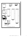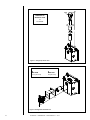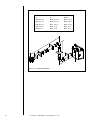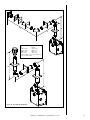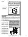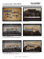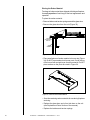
1
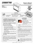
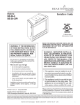
Installers Guide Model: 6000TRS-CE 0086 WARNING: If the information in these instructions is not followed exactly, a fire or explosion may result causing property damage, personal injury, or death. • Do not store or use gasoline or other flammable vapors and liquids in the vicinity of this or any other appliance. • What to do if you smell gas - Do not try to light any appliance - Do not touch any electrical switch. Do not use any phone in your building. - Immediately call your gas supplier from a neighbor’s phone. Follow the gas supplier’s instructions. - If you cannot reach your gas supplier, call the fire department. • Installation and service must be performed by a qualified installer, service agency, or the gas supplier. This is a room sealed appliance and no other ventilation is required than what is provided. Please contact your Heat & Glo dealer with any questions or concerns. For the number of your nearest Heat & Glo dealer, please visit www.heatnglo.com. Printed in U.S.A. Copyright 2013 Heat & Glo, a brand of Hearth & Home Technologies 7571 215th Street West, Lakeville, MN 55044, USA WARNING HOT SURFACES! Glass and other surfaces are hot during operation AND cool down. Hot glass will cause burns. • DO NOT touch glass until it is cooled • NEVER allow children to touch glass • Keep children away • CAREFULLY SUPERVISE children in same room as fireplace. • Alert children and adults to hazards of high temperatures. High temperatures may ignite clothing or other flammable materials. • Keep clothing, furniture, draperies and other flammable materials away. This appliance has been supplied with an integral barrier to prevent direct contact with the fixed glass panel. DO NOT operate the appliance with the barrier removed. READ THIS MANUAL BEFORE INSTALLING OR OPERATING THIS APPLIANCE. THIS INSTALLERS GUIDE must be left with appliance FOR FUTURE REFERENCE. These instructions are only valid if the following country symbol is on the appliance. If this symbol is not present on the appliance, it is necessary to refer to the technical instructions which will provide the necessary information concerning the modification of the appliance to the conditions of use for the country. These instructions are valid for the following countries: GB, IE This product is covered by one or more of the following patents: (United States) 5601073, 5613487, 5647340, 5890485, 5941237, 6006743, 6019099, 6053165, 6145502, 6374822, 6484712, 6601579, 6769426, 6863064, 7077122, 7098269, 7258116, 7470729, 8147240 or other U.S. and foreign patents pending. 2000-945B 1 Heat & Glo • 6000TRS-CE • 2049-900 Rev. R • 3/13 SAFETY AND WARNING INFORMATION 2 ! Read and understand all instructions carefully before starting the installation. Failure to follow these installation instructions may result in a possible fire hazard and will void the warranty. ! Prior to the first firing of the fireplace, read the Using Your Fireplace section of the Users Guide. ! Do not use this appliance if any part has been under water. Immediately call a qualified service technician to inspect the unit and to replace any part of the control system and any gas control which has been under water. ! This unit is not for use with solid fuel. ! Installation and repair should be performed by a qualified service person. The appliance and flue system should be inspected before initial use and at least annually by a professional service person. ! Always keep the appliance clear and free from combustible materials, petrol, and other flammable vapors and liquids. ! Never obstruct the flow of combustion and ventilation air. Keep the front of the appliance clear of all obstacles and materials for servicing and proper operations. ! Due to the high temperature, the appliance should be located out of traffic areas and away from furniture and draperies. Clothing or flammable material should not be placed on or near the appliance. ! Children and adults should be alerted to the hazards of high surface temperature and should stay away to avoid burns or clothing ignition. Young children should be carefully supervised when they are in the same room as the appliance. ! These units MUST use one of the fluing systems described in the Installing the Fireplace section of the Installers Guide. No other flue systems or components may be used. ! This gas appliance and flue assembly must be vented directly to the outside and must never be attached to a chimney serving a separate solid fuel burning appliance. Each gas appliance must use a separate flue system. Common flue systems are prohibited. ! Inspect the external terminal cap on a regular basis to make sure that no debris is interfering with the air flow. ! The glass door assembly must be in place and sealed, and the trim door assembly must be in place on the appliance before the unit can be placed into safe operation. ! Do not operate this appliance with the glass door removed, cracked, or broken. Replacement of the glass door should be performed by a licensed or qualified service person. Do not strike or slam the glass door. ! The glass door assembly shall only be replaced as a complete unit, as supplied by the gas appliance manufacturer. No substitute material may be used. ! Do not use abrasive cleaners on the glass door assembly. Do not attempt to clean the glass door when it is hot. ! Turn off the gas before servicing this appliance. It is recommended that a qualified service technician perform an appliance check-up at the beginning of each heating season. ! Any safety screen or guard removed for servicing must be replaced before operating this appliance. ! This appliance is intended for use on a gas installation with a governed meter. Heat & Glo • 6000TRS-CE • 2049-900 Rev. R • 3/13 Safety and Warning Information....................................2 Service Parts List............................................................4 Section 1: Approvals and Regulations..........................7 Table of Contents Appliance Certification...................................................7 Installation Regulations.................................................7 Section 2: Getting Started..............................................8 Introducing the Heat & Glo Gas Fireplaces...................8 Pre-installation Preparation...........................................8 Section 3: Installing the Fireplace...............................10 Step 1 Locating the Fireplace...................................10 Step 2 Framing the Fireplace....................................11 Step 3 Installing the Flue System..............................12 A. Flue System Approvals..............................12 B. Installing Flue Components.......................20 C. Flue Termination........................................24 Step 4 Positioning, Leveling and Securing the Fireplace...................................29 Step 5 The Gas Control Systems..............................29 Step 6 The Gas Supply Line.....................................30 Step 7 Gas Pressure Requirements.........................31 Step 8 Wiring the Fireplace.......................................31 Step 9 Finishing........................................................32 Step 10Installing Trim, Logs & Ember Material.............33 Installing the Trim...........................................33 Positioning the Logs......................................34 Placing the Ember Material............................36 Step 11 Before Lighting the Fireplace.........................37 Step 12Lighting the Fireplace....................................38 After the Installation ......................................38 Section 4: Maintaining and Servicing Your Fireplace.............................................39 Section 5: Troubleshooting..........................................41 Limited Lifetime Warranty................................................44 = Contains updated information. Heat & Glo • 6000TRS-CE • 2049-900 Rev. R • 3/13 3 6000TRS-CE Service Parts Beginning Manufacturing Date: Jan 2004 Ending Manufacturing Date: Active 36” Gas Fireplace - Dv Log Set Assembly 4 3 2 1 5 9 8 10 11 12 15 14 7 13 16 6 17 19 18 Part number list on following page. 4 Heat & Glo • 6000TRS-CE • 2049-900 Rev. R • 3/13 03/13 6000TRS-CE Service Parts Beginning Manufacturing Date: Jan 2004 Ending Manufacturing Date: Active IMPORTANT THIS IS DATED INFORMATION: When requesting service or replacement parts for your appliance please provide model number and serial number. All parts listed in this manual may be ordered from an authorized dealer. ITEM DESCRIPTION COMMENTS PART NUMBER Log Set Assembly LOGS-6TRSCE 1 Log #1 SRV2049-700 2 Log #2 SRV2049-701 3 Log #3 SRV385-723 4 Log #4 SRV385-721 5 Log #5 SRV385-722 6 Junction Box 546-250A Refractory Kit BRICK-6000-FB 7 Refractory, Right SRV2027-372 8 Refractory, Back SRV2027-370 9 Refractory, Left SRV2027-371 10 Exhaust Baffle 2049-101 11 Grate 2049-020 Burner Assembly N 2049-010 Burner Assembly P 2049-012 Burner Assembly B 2049-014 13 Base Refractory 2049-102 14 Glass Door Assembly GLA-6TRXI 15 Insulation Board 385-401 16 Surround 17 Top Louver 392-182A 18 Dress Guard 392-180A 19 Hood SRV60-143-BK 12 Pre Aug 2009 SRV2101-260 Post Aug 2009 2166-019 Gasket Assembly 2166-081 Contains Burner neck, shutter bracket, vent, seal cap, and valve plate gaskets Glass Latch Assembly Pkg of 2 33858/2 High Temp Limit Switch 046-018A Exhaust Restrictor 530-299 Mineral Wool 050-721 Touch-Up Paint TUP-GBK-12 Additional service part numbers appear on following page. Heat & Glo • 6000TRS-CE • 2049-900 Rev. R • 3/13 5 6000TRS-CE Service Parts Beginning Manufacturing Date: Jan 2004 Ending Manufacturing Date: Active #20 valve Assembly 20.1 20.2 20.3 20.4 20.6 20.5 20.7 20.8 20.9 20.10 20.11 IMPORTANT THIS IS DATED INFORMATION: When requesting service or replacement parts for your appliance please provide model number and serial number. All parts listed in this manual may be ordered from an authorized dealer. ITEM DESCRIPTION COMMENTS PART NUMBER Pilot Assembly N 529-550A Pilot Assembly P/B 529-551A Pilot Bracket 2049-105 Orifice N (#33C) 582-833 Orifice P (1.8 MM) 582-818 Orifice B (#52C) 582-852 20.4 12" Flex 383-302A 20.5 Valve Bracket 2118-104 20.6 Flex Assembly 302-330A 20.7 Piezo Ignitor 291-513 20.8 Wire Assembly 049-552A 20.9 On/ Off Rocker Switch 060-521A Valve N 060-524 Valve P 060-526 20.1 20.2 20.3 20.10 20.11 Pkg of 5 Male Connector 303-315/5 Conversion Kits 6 Natural to Propane NGK-6TRS-CE Propane to Butane LPK-6TRS-CE Butane to Propane BGK-6TRS-CE Regulator N 230-1570 Regulator P/B 230-1520 Pilot Orifice N 529-512 Pilot Orifice P/ B 200-2630 Heat & Glo • 6000TRS-CE • 2049-900 Rev. R • 3/13 Appliance Certification The Heat & Glo fireplace models discussed in this Installers Guide have been tested to certification standards and listed by the applicable laboratories. MODEL 6000TRS-CE LABORATORY BSI TYPE Gas Fireplace CERTIFICATION STANDARD BS EN 613:2001 (Amd 1) Installation Regulations Before installation check that local distribution conditions, nature of gas and pressure, and adjustment of the appliance are compatible. 1 Approvals and Regulations This appliance must be installed with the rules in force, and used only in a sufficiently ventilated space. Consult instructions before installation and use of this appliance. Heat & Glo • 6000TRS-CE • 2049-900 Rev. R • 3/13 7 2 Getting Started Introducing the Heat & Glo Gas Fireplaces Heat & Glo direct flue gas fireplaces are designed to operate with all combustion air siphoned from outside of the building and all exhaust gases expelled to the outside. The information contained in this Installers Guide, unless noted otherwise, applies to all models and gas control systems. Gas fireplace diagrams, including the dimensions, are shown in this section. Pre-installation Preparation This gas fireplace and its components are tested and safe when installed in accordance with this Installers Guide. Report to your dealer any parts damaged in shipment, particularly the condition of the glass. Do not install any unit with damaged, incomplete, or substitute parts. The flue system components and trim doors are shipped in separate packages. The gas logs are packaged separately and must be field installed. Read all of the instructions before starting the installation. Follow these instructions carefully during the installation to ensure maximum safety and benefit. Failure to follow these instructions will void the owner’s warranty and may present a fire hazard. The Heat & Glo Fireplace Products, Inc. Warranty will be voided by, and Heat & Glo Fireplace Products, Inc. disclaims any responsibility for, the following actions: • Installation of any damaged fireplace or flue system component. • Modification of the fireplace or direct flue system. • Installation other than as instructed by Heat & Glo Fireplace Products, Inc. • Improper positioning of the gas logs or the glass door. • Installation and/or use of any component part not manufactured and approved by Heat & Glo Fireplace Products, Inc., not withstanding any independent testing laboratory or other party approval of such component part or accessory. ANY SUCH ACTION MAY POSSIBLY CAUSE A FIRE HAZARD. 8 Heat & Glo • 6000TRS-CE • 2049-900 Rev. R • 3/13 When planning a fireplace installation, it’s necessary to determine: • Where the unit is to be installed. • The flue system configuration to be used. • Gas supply piping. • Electrical wiring. • Framing and finishing details. • Whether optional accessories—devices such as a fan, wall switch, or remote control—are desired. If the fireplace is to be installed on carpeting or tile, or on any combustible material other than wood flooring, the fireplace should be installed on a metal or wood panel that extends the full width and depth of the fireplace. L M CL J K N TOP VIEW H GAS LINE ACCESS R C CL I D G O E Q B A P LEFT SIDE F RIGHT SIDE FRONT VIEW Location Centimeters Location Centimeters A 104,1 J 54,6 B 91,8 K 29,7 C 85,1 L 72,4 D 87,9 M 36,2 E 57 N 21,6 F 24,6 O 73 G 68,3 P 21,6 H 15,2 dia Q 25 I 101,9 R 91,8 Figure 1. Diagram of the 6000TRS-CE Heat & Glo • 6000TRS-CE • 2049-900 Rev. R • 3/13 9 3 Installing the Fireplace Step 1 Locating the Fireplace The diagram below shows space and clearance requirements for locating a fireplace within a room. NOTE: THE REAR STANDOFF MAY NEED TO BE REMOVED WHEN VENTING AT 45º G 1,3 cm A B ALCOVE INSTALLATION A B E C TOP FLUE ONE 90º ELBOW REAR FLUE, HORIZONTAL TERMINATION TWO 90º ELBOWS B D I REAR FLUE ONE 90º ELBOW REAR FLUE NO ELBOWS B B CL D F H cm D D A B C D E F G H I 130 107 183 144 See Section F. Mantel Projections 56 45 20 73 Figure 2. Fireplace Dimensions, Locations, and Space Requirements Clearance Requirements The top and back of the fireplace are defined by stand-offs. The minimum clearance to a perpendicular wall extending past the face of the fireplace is 7.62 cm. The back of the fireplaces may be recessed into combustible construction (see Figure 3). MODEL: 6000TRS-CE RECESSED DEPTH: 54.6 cm Minimum Clearances from the Fireplace to Combustible Materials Glass Front Floor Back of Fireplace Sides of Fireplace Top of Fireplace Ceiling 91.4 cm 0 1.3 cm 1.3 cm 8.9 cm 79 cm Minimum Clearances from the Flue Pipe to Combustible Materials For Horizontal Sections Top Bottom Sides For Vertical Sections 7.6 cm 2.54 cm 2.54 cm 2.54 cm Figure 3. Minimum Clearances 10 Heat & Glo • 6000TRS-CE • 2049-900 Rev. R • 3/13 At Wall Firestops Top Bottom Sides 6.4 cm 1.3 cm 2.54 cm Step 2 Framing the Fireplace Fireplace framing can be built before or after the fireplace is set in place. Framing should be positioned to accommodate wall coverings and fireplace facing material. The diagram below shows framing reference dimensions. CAUTION MEASURE FIREPLACE DIMENSIONS, AND VERIFY FRAMING METHODS AND WALL COVERING DETAILS, BEFORE FRAMING CONSTRUCTION BEGINS. D* E* B* C Framing should be constructed of 2 X 4 lumber or heavier. A 8 cm WALL STUD 14 cm NON-COMBUSTIBLE ZONE IS DEFINED BY 8 CM ABOVE THE ELBOW FOR THE ENTIRE WIDTH AND DEPTH (BEHIND THE FRONT HEADER) OF THE FIREBOX. * Note: Dimension B taken from finished hearth frame. Dimensions D and E taken from bottom of unit. A B C 107 cm 102 cm 56 cm D E 68,3 cm 106 cm Figure 4. Framing Dimensions Heat & Glo • 6000TRS-CE • 2049-900 Rev. R • 3/13 11 A. Flue System Approvals Step 3 Installing the Flue System These models have flue starting collars on both the top and the back of the unit. Depending upon the installation, decide which ONE set of starting collars will be used to attached the flue system. The starting collar sealing cap must remain on the starting collar NOT used. These models use DVP-series direct flue components when using the TOP and REAR flue collars. Approved flue system components are labeled for identification. NO OTHER FLUEING SYSTEMS OR COMPONENTS MAY BE USED. Detailed installation instructions are included with each flue termination kit and should be used in conjunction with this Installers Guide. Figure 4 shows flue system components and terminations. Identifying Flue Components The flue systems installed on this gas fireplace may include one, two, or three 90° elbow assemblies. The relationships of vertical rise to horizontal run in flue configurations using 90° elbows MUST BE strictly adhered to. The rise to run relationships are shown in the flueing drawings and tables on the next several pages. Note: Two 45° elbows may be used in place of one 90° elbow. You MUST always maintain the MAXIMUM and MINIMUM riseto-run ratios in the flue system when using 45° elbows. STORM COLLAR VERTICAL TERMINATION ROOF FLASHING HORIZONTAL TERMINATION HORIZONTAL PIPE SUPPORT PIPE LENGTH WALL FIRESTOP 90 DEGREE ELBOW CEILING FIRESTOP FLUE SYSTEM TERMINATION KITS DVP-SERIES DVP-TVHW DVP-TRAP Figure 5. Flue Components and Terminations 12 Heat & Glo • 6000TRS-CE • 2049-900 Rev. R • 3/13 WALL BRACKET 10.2 cm 15.2 cm 30.5 cm DVP4 DVP6 DVP12 36.2 cm 31.0 cm MAX. 5.1 cm MIN. 61.0 cm 91.4 cm DVP12A 20 .3 cm 121.9 cm 25.1 cm DVP24 45.0º 26 cm 26 cm DVP45 DVP36 28.6 cm 18.4 cm 3.2 cm TYP 21.7 cm DVP48 1.3 cm TYP 31.9 cm DVP90ST NOTE: PIPES OVERLAP 3,2 cm AT EACH JOINT. Figure 6. DVP-Series Balanced Flue Component Specifications (127 mm inner pipe / 203 mm outer pipe) Heat & Glo • 6000TRS-CE • 2049-900 Rev. R • 3/13 13 CAP STRAIGHT UP VERTICAL FLUE V 11.8 m MAX. V Figure 7. Straight up Vertical Flue STRAIGHT OUT HORIZONTAL FLUE H MIN. RUN 13.1” (33.2 cm) H MAX. RUN 24” (61.0 cm) H Figure 8. Straight Out Horizontal Flue 14 Heat & Glo • 6000TRS-CE • 2049-900 Rev. R • 3/13 V H FLUE WITH ONE (1) 90o elbow V H MIN. 30.5 cm MAX. 61.0 cm MIN. 61.0 cm MAX. 1.22 m MIN. 91.4 cm MAX. 1.86 m MIN. 1.22 m MAX. 2.48 m MAX. 7.3 m Figure 9. Flue with One 90° Elbow MAX. 2.48 m FLUE WITH ONE (1) 90o elbow V H MIN. 30.5 cm MAX. 1.22 m MIN. 61.0 cm MAX. 2.4 m MIN. 91.4 cm MAX. 3.7 m MIN. 1.22 m MAX. 4.9 m V + H = MAX 7.3 m H = MAX. 2.4 m H V NOTE: For corner installations: A 15.2 cm MINIMUM length of straight pipe must be first attached to the fireplace before 90o elbow. This will allow the flue pipe to clear the top standoffs. NOTE: If a 90º elbow is first attached to the unit, the maximum horizontal run is 3 feet (91.4 cm). Figure 10. Flue with One 90° Elbow Heat & Glo • 6000TRS-CE • 2049-900 Rev. R • 3/13 15 FLUE WITH TWO (2) 90° ELBOWS H H + H1 V MIN. 30.5 cm MAX. 61.0 cm MAX. 1.22 m MIN. 61.0 cm MAX. 61.0 cm MAX. 2.48 m MIN. 91.4 cm MAX. 1.22 m MAX. 3.72 m MIN. 1.22 m MAX. 1.8 m MAX. 4.9 m MAX. 6.1 m MAX. 1.8 m MAX. 4.9 m H1 V H Figure 11. Flue with Two 90° Elbows 16 Heat & Glo • 6000TRS-CE • 2049-900 Rev. R • 3/13 H1 V H FLUE WITH TWO (2) 90° ELBOWS V MIN. 30.5 cm MIN. 61.0 cm MIN. 91.4 cm MIN. 1.22 m H + H1 MAX. 1.22 m MAX. 2.4 m MAX. 3.7 m MAX. 4.9 m V+H+H1= MAX. 11.8 m H+H1= MAX. 4.9 m V+V1+H1= MAX. 12.97 m V1 V H Figure 12. Flue with Two 90° Elbows Heat & Glo • 6000TRS-CE • 2049-900 Rev. R • 3/13 17 FLUE WITH THREE (3) 90° ELBOWS H H + H1 V MIN. 30.5 cm MIN. 61.0 cm MIN. 91.4 cm MIN. 1.22 m MAX. MAX. MAX. MAX. 61.0 cm 1.22 m 1.86 m 2.48 m H = MAX. 2.48 m MAX. 4.9 m MAX. MAX. MAX. MAX. NOTE: V + V1 + H + H1 = MAX. 10.97 m V1 V H1 FLUE WITH THREE (3) 90° ELBOWS V H MIN. 30.5 cm MIN. 61.0 cm MIN. 91.4 cm MIN. 1.22 m MAX. 6.1 m H + H1 + H2 MAX. 61.0 cm MAX. 61.0 cm MAX. 1.22 m MAX. 1.86 m MAX. 1.86 m MAX. MAX. MAX. MAX. MAX. 1.22 m 2.48 m 3.6 m 4.9 m 4.9 m V H2 H1 Figure 13. Flue with three 90° elbows 18 Heat & Glo • 6000TRS-CE • 2049-900 Rev. R • 3/13 1.22 m 2.48 m 3.6 m 4.9 m FLUE WITH THREE (3) 90° ELBOWS V H + H1 MIN. 30.5 cm MIN. 61.0 cm MIN. 91.4 cm MIN. 1.22 m MAX. MAX. MAX. MAX. 1.22 m 2.4 m 3.7 m 4.9 m V + V1 + H + H1 = MAX. 10.97 m H + H1 = MAX. 4.9 m H1 V1 V H V1 H1 H V FLUE WITH THREE (3) 90° ELBOWS V H + H1 MIN. 30.5 cm MIN. 61.0 cm MIN. 91.4 cm MIN. 1.22 m MAX. MAX. MAX. MAX. 1.22 m 2.4 m 3.7 m 4.9 m V + V1 + H + H1 = MAX. 10.97 m H + H1 = MAX. 4.9 m Figure 14. Flue with three 90° elbows Heat & Glo • 6000TRS-CE • 2049-900 Rev. R • 3/13 19 B. Installing Flue Components After determining which set of starting collars will be used (top or rear), follow venting instructions accordingly. Venting Out the Rear Flue Remove the installed rear seal cap from the rear starting collars by cutting the strap at each end (See Figure 15). Follow the flue configuration tables accordingly. Remove the 12.7 cm diameter heat shield from the 1.27 cm diameter collar by sliding it out. Remove insulation piece. ! Warning: the top heat shield (inside the firebox) must remain attached if the flue system is attached to the rear starting collars. See figure 15. Venting Out the Top Flue Remove the top flue collar seal cap by cutting the strap on each end. Remove both pieces of insulation inside the top two starting collars (see Figure 15). Remove the 10.2 cm diameter heat shield from the 10.2 cm diameter collar by sliding it out. You have to take the glass off again for positioning the logs when the unit is finally installed in place and finished around it. Reinstall the glass door. Attach flue system to the top starting collars. ! ! ! WARNING: THE REAR FLUE COLLAR SEAL CAP MUST REMAIN ATTACHED TO THE REAR FLUE COLLARS IF THE FLUE SYSTEM IS ATTACHED TO THE TOP STARTING COLLARS. SEE FIGURE 15. WARNING: FAILURE TO REMOVE INSULATION IN THE SET OF COLLARS YOU ARE USING COULD CAUSE A FIRE. WARNING: YOU MUST LEAVE THE INSULATION IN PLACE IN THE SET OF COLLARS YOU ARE NOT USING. Insert screwdriver or similar object here to remove cap. Venting Out Top Venting Out Rear SEAL CAP SEAL CAP HEAT SHIELD DISCARD INSULATION CUT HERE Figure 15 20 Heat & Glo • 6000TRS-CE • 2049-900 Rev. R • 3/13 HEAT SHIELD INSULATION, DISCARD BOTH PIECES Installing Flue Components 1. Attaching the First Flue Component to the Starting Collars: A.On the REAR of the heater • To attach the first flue component to the starting collars on the rear of the heater make sure that the heater gasket supplied with the heater seals between the first flue component and the outer heater wrap. • The first 90° elbow installed in the flue system of a rear flueing heater MUST BE in a vertical position. B.On the TOP of the heater To attach the first flue component to the starting collars on the top of the heater: • Slide the male end of the inner flue of the pipe section into the inner collar on the heater. At the same time, insert the outer flue into the outer collar on the heater. Push the flue section into the appliance collar until all the lances (see Figure 16) have snapped in place. Tug slightly on the flue to confirm that it has completely locked into place. • Slide the ceramic fiber pad over the first flue section and place it flush to the fireplace. Continue to add vent components. Figure 16. WARNING: ENSURE THAT THE HEATER GASKET SUPPLIED WITH THE HEATER SEALS BETWEEN THE FIRST FLUE COMPONENT AND THE OUTER HEATER WRAP. C. Continue Adding Flue Components To continue adding flue components in accordance with the pre-planned flue system configuration: • Ensure that each succeeding flue component is securely fitted and locked into the preceding component in the flue system. Note: Make sure that seams are NOT aligned to prevent unintentional disconnection. • For elbows that are changing the flue direction, two screws minimum should be put in the outer flue at the joint to prevent the elbow from rotating. 2. Install Support Brackets For Horizontal Runs - The flue system must be supported every five (5) feet (152.4 cm) of horizontal run by a horizontal pipe support. To install support brackets for horizontal runs: • Place the pipe supports around the flue pipe. • Nail the pipe supports to the framing members. Heat & Glo • 6000TRS-CE • 2049-900 Rev. R • 3/13 21 For Vertical Runs - The flue system must be supported every 240 cm above the heater flue outlet by wall brackets. To install support brackets for vertical runs: • Attach wall brackets to the flue pipe and secure the wall bracket to the framing members with nails or screws. WALL BRACKET WALL STUD 2,4 m FLUE OUTLET 2,5 cm MINIMUM Figure 17. Installing Support Brackets 3. Install Firestops For Horizontal Runs - Firestops are REQUIRED on both sides of a combustible wall through which the flue passes. To install firestops (heat shield) for horizontal runs that pass through either interior or exterior walls: • Cut a 25,4 cm X 30,5 cm hole through the wall. • Position the firestops on both sides of the hole previously cut and secure the firestops with nails or screws. • The pipe opening of the firestops MUST BE placed towards the bottom of the firestop. • Continue the flue run through the firestop. 22 Heat & Glo • 6000TRS-CE • 2049-900 Rev. R • 3/13 10" (25.4 cm) INTERIOR WALL SHIELD 12" (30.5 cm) Figure 18. Flue Pipe & Firestop For Vertical Runs - One firestop is REQUIRED at the hole in each ceiling through which the flue passes. To install firestops for vertical runs that pass through ceilings: • Position a plumb bob directly over the center of the vertical flue component. • Mark the ceiling to establish the center point of the flue. • Drill a hole or drive a nail through this center point. • Check the floor above for any obstructions, such as wiring or plumbing runs. • Reposition the heater and flue system, if necessary, to accommodate the ceiling joists and/or obstructions. • Cut a 25.4 cm X 30.5 cm hole through the ceiling, using the firestop pipe opening as a guide. • Frame the hole with framing lumber the same size as the ceiling joists. 10" (25.4 cm) 10” ( 25.4 cm) CHIMNEY HOLE NEW FRAMING MEMBERS EXISTING CEILING JOISTS CEILING Figure 19. Hole and New Framing Members Heat & Glo • 6000TRS-CE • 2049-900 Rev. R • 3/13 23 If the area above the ceiling is NOT an attic, position and secure the ceiling firestop on the ceiling side of the previously cut and framed hole. JOIST CEILING NAILS (4 REQUIRED) CEILING FIRESTOP Figure 20. Ceiling Firestop (Ceiling Side) If the area above the ceiling IS an attic, position and secure the firestop on top of the previously framed hole. NAILS (4 REQUIRED) RAFTER CEILING CEILING FIRESTOP Figure 21. Attic Firestop C. Flue Termination CAUTION: IF EXTERIOR WALLS ARE FINISHED WITH VINYL SIDING, IT IS NECESSARY TO INSTALL THE VINYL PROTECTOR KIT (VPK-DV) TO THE TOP OF THE EXTERIOR FIRESTOP FOR ALL ROUND TERMINATION CAPS. For Horizontal Terminations using the DVP-TRAP To attach and secure the termination to the last section of horizontal flue: • The rear flue heat shield MUST be placed 2.54 cm above the top of the flue between the wall shield and the base of the termination cap. • One section of the heat shield is attached to the wall shield. The other is attached to the termination cap in the same manner (see Figure 22). 24 Heat & Glo • 6000TRS-CE • 2049-900 Rev. R • 3/13 • The heat shield sections will overlap to match the wall thickness (depth). The small leg in the shield rests on top of the flue to properly space it from the pipe section (see Figure 22). Interior Wall Shield Rear Vent Heat Shield 3.8 cm min. overlap Outer Flue Inner Flue 3.8 cm min. Overlap INTERIOR EXTERIOR Figure 22. Venting through the Wall • The termination kit should pass through the wall firestops from the exterior of the building. • Adjust the termination cap to its final exterior position on the building and interlock the flue sections. ! WARNING: THE TERMINATION CAP MUST BE POSITIONED SO THAT THE ARROW IS POINTING UP. • Use a high-temperature sealant gasket to seal between the pipe and exterior firestop. Heat & Glo • 6000TRS-CE • 2049-900 Rev. R • 3/13 25 Figure 23 DVP Termination Cap For Vertical Terminations - To locate the flue and install the flue sections: • Locate and mark the flue center point on the underside of the roof, and drive a nail through the center point. • Make the outline of the roof hole around the center point nail. • The size of the roof hole framing dimensions depend on the pitch of the roof. There MUST BE a 2.5 cm clearance from the vertical flue pipe to combustible materials. • Mark the roof hole accordingly. • Cover the opening of the installed flue pipes. • Cut and frame the roof hole. • Use framing lumber the same size as the roof rafters and install the frame securely. Flashing anchored to the frame must withstand heavy winds. • Continue to install concentric flue sections up through the roof hole and up past the roof line until you reach the appropriate distance above the roof. To seal the roof hole, and to divert rain and snow from the flue system: • Attach a flashing to the roof using nails, and use a nonhardening mastic around the edges of the flashing base where it meets the roof. • Attach a storm collar over the flashing joint to form a water-tight seal. Place non-hardening mastic around the joint, between the storm collar and the vertical pipe. • Slide the termination cap over the end of the flue pipe and snap into place. 26 Heat & Glo • 6000TRS-CE • 2049-900 Rev. R • 3/13 WARNING:FOLLOW NATIONAL REGULATIONS AND CODES OF PRACTICE FOR MINIMUM CLEARANCES FROM GAS TERMINALS, AND PLACEMENT OF GAS TERMINAL. NOTE This also pertains to vertical flue systems installed on the outside of the building. 51 cm VERTICAL WALL LOWEST DISCHARGE OPENING TERMINATION CAP X 30,5 cm ROOF PITCH IS X/ 30,5 cm H (MIN.) - MINIMUM HEIGHT FROM ROOF TO LOWEST DISCHARGE OPENING Angle H (Min.) M 0°-26.6° ................................................ 0.30* 26.6°-30.3°................................................ 0.38* 30.3°-33.7°................................................ 0.46* 33.7°-36.9°................................................ 0.61* 36.9°-39.8°................................................ 0.76 39.8°-42.5°................................................ 0.99 42.5°-45.0°................................................ 1.22 45.0°-49.4°................................................ 1.52 49.4°-53.1°................................................ 1.83 53.1°-56.3°................................................ 2.13 56.3°-59.0°................................................ 2.29 59.0°-60.3°................................................ 2.44 *.91 M minimum in snow regions Figure 24. Minimum Height from Roof to Lowest Discharge Opening Heat & Glo • 6000TRS-CE • 2049-900 Rev. R • 3/13 27 M N P R Q (See Note 2) See Notes 3 & 4 v T v S Electrical Service S v D* v V = VENT TERMINAL X = AIR SUPPLY INLET A = 30.5 cm�����������������clearances above grade, veranda, (See Note 1) porch, deck or balcony B = 30.5 cm�����������������clearances to window or door that may be opened, or to permanently closed window. (Glass) D* = 50.8 cm�����������������vertical clearance to unventilated soffit or to ventilated soffit located above the terminal 84.8 cm������������������for vinyl clad soffits and below electrical service F = 22.9 cm����������������clearance to outside corner G = 15.3 cm�����������������clearance to inside corner H = 91.4 cm�����������������not to be installed above a gas meter/regulator assembly within 91.4 cm horizontally from the center-line of the regulator I = 91.4 m�������������������clearance to gas service regulator flue outlet J = 22.9 cm�������������������clearance to non-mechanical air supply inlet to building or the combustion air inlet to any other appliance = AREA WHERE TERMINAL IS NOT PERMITTED K = 91.4 m���������������������clearance to a mechanical (powered) air supply inlet L = 2.1 m�����������������������c l e a r a n c e a b o v e p a v e d (See Note 1) sidewalk or a paved driveway located on public property M* = 50.8 cm�������������������clearance under veranda, porch, deck, balcony or overhang 118.9 m ������������������vinyl S = 15.3 cm��������������������clearance from sides of elec(See Note 5) trical service T = 30.5 cm���������������������clearance above electrical (See Note 5) service Alcove Applications N = 15.3 cm ������������������non-vinyl sidewalls 30.5 cm ������������������vinyl sidewalls P = 2.4 m QMIN 1 cap 2 caps 3 caps 4 caps .91 m 1.8 m 2.7 m 3.7 m QMIN = # termination caps x 3 RMAX 2 x Q ACTUAL 1 x Q ACTUAL 2/3 x Q ACTUAL 1/2 x Q ACTUAL RMAX = (2 / # termination caps) x QACTUAL * only permitted if veranda, porch, deck or balcony is fully open on a minimum of 2 sides beneath the floor, or meets Note 2. NOTE 3: Local codes or regulations may require different clearances. NOTE 1: On private property where termination is less than 2.1 M above a sidewalk, driveway, deck, porch, veranda or balcony, use of a listed cap shield is suggested. (See vents components page) NOTE 4: Termination caps may be hot. Consider their proximity to doors or other traffic areas. NOTE 2: Termination in an alcove space (spaces open only on one side and with an overhang) are permitted with the dimensions specified for vinyl or non-vinyl siding and soffits. 1. There must be 91.4 cm minimum between termination caps. 2. All mechanical air intakes within 3.0 M of a termination cap must be a minimum of 91.4 cm below the termination cap. 3. All gravity air intakes within 91.4 cm of a termination cap must be a minimum of 30.5 cm below the termination cap. NOTE 5: Location of the vent termination must not interfere with access to the electrical service. NOTE: Vent system termination is permitted in porch areas with two or more sides open. You must follow all side walls, overhang and ground clearances as stated in the instructions. Heat & Glo assumes no responsibility for the improper performance of the appliance when the venting system does not meet these requirements. Figure 25 Vent Termination Minimum Clearances CAUTION: IF EXTERIOR WALLS ARE FINISHED WITH VINYL SIDING, IT IS SUGGESTED THAT A VINYL PROTECTOR KIT BE INSTALLED. 28 Heat & Glo • 6000TRS-CE • 2049-900 Rev. R • 3/13 Step 4 Positioning, Leveling, and Securing the Fireplace The diagram below shows how to properly position, level, and secure the fireplace. 1. Place the fireplace into position. 2. Level the fireplace from side to side and from front to back. 3. Shim the fireplace with non-combustible material, such as sheet metal, as necessary. NAILING TABS (BOTH SIDES) 4. Secure the fireplace to the framing by nailing or screwing. Figure 26. Proper Positioning, Leveling, and Securing of a Fireplace Step 5 The Gas Control System ! WARNING: THIS UNIT IS NOT FOR USE WITH SOLID FUEL. Standing Pilot Ignition System This system includes millivolt control valve, standing pilot, thermopile/thermocouple flame sensor, and piezo ignitor. ! WARNING: 230 VAC MUST NEVER BE CONNECTED TO A CONTROL VALVE IN A MILLIVOLT SYSTEM. STANDING PILOT Figure 27. Gas Control System Heat & Glo • 6000TRS-CE • 2049-900 Rev. R • 3/13 29 Step 6 The Gas Supply Line Note: Have the gas supply line installed by a qualified service technician in accordance with all building regulations. Note: Before the first firing of the fireplace, the gas supply line should be purged of any trapped air. NOTE: Consult local building regulations to properly size the gas supply line leading to the (Rp 1/2”) hook-up at the unit. This gas inlet connection is ISO 7-Rp 1/2 (BSP Rp 1/2). To install the gas supply line: • When attaching the pipe, support the control so that the lines are not bent or torn. • After the gas line installation is complete, use a soap solution to carefully check all gas connections for leaks. ! Warning: DO NOT USE AN OPEN FLAME TO CHECK FOR GAS LEAKS. • At the gas line access hole, use insulation to repack the space around the gas pipe. • Insert insulation from the outside of the fireplace and pack the insulation tightly to totally seal between the pipe and the outer casing. The gas line should be installed by a qualified service technician. GAS LINE ACCESS Figure 28 30 Heat & Glo • 6000TRS-CE • 2049-900 Rev. R • 3/13 Step 7 Gas Pressure Requirements Pressure requirements for Heat & Glo gas fireplaces are shown in the table below. Natural Gas Propane Butane Natural Gas (G20) (G31) (G30) (G25) Inlet Pressure 20 mbar Manifold Pressure 4-8.7 mbar Gas Rate .54 m3 /h 30 or 50 mbar 30 or 50 mbar 15.7-25 mbar .24 m3 15.7-25 mbar /h .16 m3 /h 25 mbar 4-8.7 mbar .54 m3/h Max. Input(NETCV) 10.0 kW 10.0 kW 9.5 kW 8.5 kW Burner Injector DMS 33 1.8 mm DMS 51 DMS 33 Pilot Injector 51 30 30 51 A tap is provided on the outlet side of the gas control for a test gauge connection to measure the manifold pressure. To measure inlet pressure, provisions must be made to attach a test gauge to the tap immediately upstream of the gas supply connection to the fireplace. The fireplace and its individual shut-off valve must be disconnected from the gas supply piping system during any pressure testing of the system at test pressures in excess of 60 mbar. If the fireplace must be isolated from the gas supply piping system by closing an individual shut-off valve, it must be of the handle-less type. Step 8 Wiring the Fireplace NOTE: Electrical wiring must be installed by a competent electrician. For Standing Pilot Ignition Wiring Appliance Requirements Optional Accessories Optional remote control kits require that 230 VAC be wired to the factory installed junction box before the fireplace is permanently installed. ! WARNING: DO NOT CONNECT 230 VAC TO THE GAS CONTROL VALVE OR THE APPLIANCE WILL MALFUNCTION AND THE VALVE WILL BE DESTROYED. Wall Switch Position the wall switch in the desired position on a wall. Run a maximum of 780 cm or less length of 0.102 cm diameter minimum wire and connect it to the fireplace ON/OFF switch pigtails. Heat & Glo • 6000TRS-CE • 2049-900 Rev. R • 3/13 31 WARNING: DO NOT CONNECT 230 VAC TO THE WALL SWITCH OR THE CONTROL VALVE WILL BE DESTROYED. ! CAUTION LABEL ALL WIRES PRIOR TO DISCONNECTION when servicing controls. WIRING ERRORS CAN CAUSE IMPROPER AND DANGEROUS OPERATION. VERIFY PROPER OPERATION AFTER SERVICING. OPTIONAL WALL SWITCH THERMOSTAT OR REMOTE THERMOCOUPLE TP/TH TP OFF ON REMOTE SWITCH PIGTAIL ON/OFF SWITCH TH THERMOPILE GAS VALVE Figure 29. Standing Pilot Ignition Wiring Diagram Step 9 Finishing Only non-combustible materials may be used to cover the black fireplace front. The following diagram shows the minimum vertical and corresponding maximum horizontal dimensions of fireplace mantels or other combustible projections above the top front edge of the fireplace. See Figures 2 , 3 and 4 for other fireplace clearances. NON-COMBUSTIBLE BOARD 20,3 18 15,2 13 10,2 7,6 5,1 2,5 8 4 9 10,2 30,5 28 25,4 23 15,2 11,4 13 18 20,3 23 25,4 28 TOP FRONT EDGE OF FIREPLACE Note: all dimensions are shown in centimeters. Figure 30. Minimum Vertical and Maximum Horizontal Dimensions of Combustibles above Fireplace ! WA R N I N G : W H E N F I N I S H I N G T H E FIREPLACE, NEVER OBSTRUCT OR MODIFY THE AIR INLET/OUTLET GRILLES IN ANY MANNER. Note: Factory installed non-combustible board may only be replaced with HHT product code SUPERM-60 material and must be fully replaced in its entirety. 32 Heat & Glo • 6000TRS-CE • 2049-900 Rev. R • 3/13 CAUTION IF JOINTS BETWEEN THE FINISHED WALLS AND THE FIREPLACE SURROUND (TOP AND SIDES) ARE SEALED, A 150º C. MINIMUM SEALANT MATERIAL MUST BE USED. THESE JOINTS ARE NOT REQUIRED TO BE SEALED. ONLY NONCOMBUSTIBLE MATERIAL (USING 150º C. MINIMUM ADHESIVE, IF NEEDED) CAN BE APPLIED AS FACING TO THE FIREPLACE SURROUND. SEE FIGURE 31. 1. Apply only noncombustible facing material to the fireplace surround. FINISH MATERIAL MAY BE COMBUSTIBLE - TOP AND SIDES OF UNIT TOP SEAL JOINT SIDE SEAL JOINT 1,3 cm 1,3 cm Figure 31. Sealant Material Step 10 Installing Trim, Refractory, Logs, and Ember Material Installing the Trim Combustible materials may be brought up to the specified clearances on the side and top front edges of the fireplace, but MUST NEVER overlap onto the front face. The joints between the finished wall, fireplace top and sides can only be sealed with a 150º C minimum sealant. Install optional marble and brass trim surround kits as desired. Marble, brass, brick, tile, or other noncombustible materials can be used to cover up the gap between the sheet rock and the fireplace. ! WARNING: CHILDREN AND ADULTS Do not obstruct or modify the SHOULD BE ALERTED TO THE HAZARDS air inlet/outlet grilles. When OF HIGH TEMPERATURES OF WORKING overlapping on both sides, SURFACES ON THESE HEATERS. WORKING leave enough space so that the SURFACES INCLUDE ALL GLASS PANELS bottom grille can be opened AND DECORATIVE DOORS. YOUNG CHILand the trim door removed. DREN SHOULD BE CAREFULLY SUPERVISED WHEN THEY ARE IN THE SAME ROOM AS THE Installing the Ceramic Re- APPLIANCE. fractory Remove dress guard, glass door and log package. Remove refractory pieces from packaging (see Figure 32). Position rear refractory piece first and then slide both side pieces through the upper guide openings until they sit firmly against the rear of the unit. See following pages for log installation instruction. Figure 32. Heat & Glo • 6000TRS-CE • 2049-900 Rev. R • 3/13 33 Log placement Instructions Log Set Assembly: LOGS-6TRSCE 1 4 2 3 5 Carefully remove the logs from the packaging. CAUTION: Logs are fragile! 1 1 Log #1 (srv2049-700): Place log #1 at the rear of the unit against the rear grate tabs with the notches on the bottom of the log lining up with the grate bars. 2 2 Log #2 (srv2049-701): Locate the bottom grooves of log #2 over the second and third grate bars. Push back against the grate tabs on these bars. 34 Heat & Glo • 6000TRS-CE • 2049-900 Rev. R • 3/13 3 3 Log #3 (srv385-723): Rest log #3 on the grooves on log #1 and log #2. 4 4 Log #4 (srv385-721): grate as shown. Rest log #4 in the groove on log #1 with its front next to the left side of the log 5 Log #5 (srv385-722): groove on log #1. 5 Push log #5 against the grate tabs on the 5th grate bar and rest its top in the If sooting occurs, the logs might need to be repositioned slightly to avoid excessive flame impingement. Heat & Glo • 6000TRS-CE • 2049-900 Rev. R • 3/13 35 Placing the Ember Material Two bags of ember material are shipped with this gas fireplace. Use only a portion of each bag for the best appearance and operation. To place the ember material: • Remove latches and tension springs around the glass door. • Remove the glass door from the unit (Figure 33). LATCHES (BOTH BOTTOM AND TOP) GLASS ASSEMBLY Figure 33. Glass Assembly • Place small pieces of ember material on burner top (Figure 34). Do NOT press embers into burner ports. Cover the top of the burner with a single layer of ember material. Do NOT place embers on the ports as noted in Figure 34. Figure 34. Placement of the Ember Material • Save the remaining ember materials for use during fireplace servicing. • Replace the glass door and a front trim door on the unit (see Replacement Parts Section of the manual.) • Replace the latches and tension springs. 36 Heat & Glo • 6000TRS-CE • 2049-900 Rev. R • 3/13 Step 11 Before Lighting the Fireplace WARNING HOT SURFACES! Glass and other surfaces are hot during operation AND cool down. Hot glass will cause burns. • DO NOT touch glass until it is cooled • NEVER allow children to touch glass • Keep children away • CAREFULLY SUPERVISE children in same room as fireplace. • Alert children and adults to hazards of high temperatures. High temperatures may ignite clothing or other flammable materials. • Keep clothing, furniture, draperies and other flammable materials away. This appliance has been supplied with an integral barrier to prevent direct contact with the fixed glass panel. DO NOT operate the appliance with the barrier removed. Before lighting the fireplace, be sure to do the following: Review safety warnings and cautions • Read the Safety and Warning Information section at the beginning of this Installers Guide. Double-check for gas leaks • Before lighting the fireplace, double-check the unit for possible gas leaks. Double-check flue terminations and front grilles for obstructions. • Before lighting the fireplace, double-check the unit for possible obstructions that could be blocking the flue terminations or the front grilles. Double-check for faulty components • Any component that is found to be faulty MUST BE replaced with an approved component. Tampering with the fireplace components is DANGEROUS and voids all warranties. A small amount of air will be in the gas supply lines. When first lighting the fireplace, it will take a few minutes for the lines to purge themselves of this air. Once the purging is complete, the fireplace will light and will operate normally. Subsequent lightings of the fireplace will not require this purging of air from the gas supply lines, unless the gas valve has been turned to the OFF position, in which case the air would have to be purged. NOTE: The fireplace should be run for 3 to 4 hours on the initial start-up. Turn it off and let it cool completely. Remove and clean the glass. Replace the glass and run the fireplace for an additional 8 hours. This will help to cure the products used in the paint and logs. Heat & Glo • 6000TRS-CE • 2049-900 Rev. R • 3/13 37 Step 12 Lighting the Fireplace You’ve reviewed all safety warnings, you’ve checked the fireplace for gas leaks, you know the flue system is unobstructed, and you’ve checked for faulty components. Now you’re ready to light the fireplace. ! After the Installation 38 WARNING: PLEASE REFER TO THE USER’S MANUAL FOR ALL CAUTIONS, SAFETY, AND WARNING INFORMATION PERTAINING TO THE LIGHTING AND OPERATION OF THE FIREPLACE. LEAVE THIS INSTALLATION MANUAL WITH THE APPLIANCE FOR FUTURE REFERENCE. Heat & Glo • 6000TRS-CE • 2049-900 Rev. R • 3/13 Fireplace Maintenance Although the frequency of your appliance servicing and maintenance will depend on use and the type of installation, you should have a qualified service technician perform an appliance checkup at the beginning of each heating season. See the table below for specific guidelines regarding each fireplace maintenance task. IMPORTANT TURN OFF THE GAS BEFORE SERVICING YOUR FIREPLACE. Type of Fireplace Maintenance Frequency By Fireplace Maintenance Task To Be Completed Replacing Old Ember Material Once annually, during the annual checkup Qualified Service Technician Brush away loose ember material near the burner. Replace old ember material with 1 cm thin pieces of Glowing Ember (050-721). New ember material should be placed on top of the burner. Save the remaining ember material and repeat this procedure at your next servicing. For more information, see Placing Ember Material in the INSTALLERS GUIDE. Cleaning Burner and Controls Once annually Qualified Service Technician Brush or vacuum the control compartment, and burner areas surrounding the logs. Checking Flame Patterns, Flame Height Periodically Qualified Service Technician/ Owner Make a visual check of your fireplace’s flame patterns. Make sure the flames are steady, not lifting or floating. See the picture in Figure 35. The thermopile/thermocouple tips should be covered with flame. See picture in Figure 36. Checking Flue System Before initial use and at least annually thereafter, more frequently if possible Qualified Service Technician/ Owner Inspect the external terminal cap on a regular basis to ensure that no debris is interfering with the flow of air, Inspect entire flue system for proper function. Cleaning Glass Door After the first 3-4 hours of use. As necessary after initial cleaning. Qualified Service Technician Remove and clean glass after the first 3 to 4 hours of use. After the initial cleaning, clean as necessary, particularly after adding new ember material. Film deposits on the inside of the glass door should be cleaned off using a household glass cleaner. NOTE: DO NOT handle or attempt to clean the door when it is hot and DO NOT use abrasive cleaners. Heat & Glo • 6000TRS-CE • 2049-900 Rev. R • 3/13 4 Maintaining and Servicing Your Fireplace 39 Make sure the flames are steady—not lifting or floating. Figure 35. Burner Flame Patterns STANDING PILOT Figure 36. Pilot Flame Patterns 40 Heat & Glo • 6000TRS-CE • 2049-900 Rev. R • 3/13 Standing Pilot Troubleshooting Symptom 1. After repeated triggering of the red or black piezo button, the spark ignitor will not light the pilot. 2. The pilot will not stay lit after carefully following the lighting instructions. Possible Cause Corrective Action a. Defective ignitor Check the spark at the electrode and pilot. If no spark and electrode wire is properly connected, replace the ignitor. b. Defective pilot or misaligned electrode (spark at electrode) Using a match, light the pilot. If the pilot lights, turn off the pilot and trigger the red or black piezo button again. If the pilot lights, an improper gas/air mixture caused the bad lighting and a longer purge period is recommended. If the pilot will not light, ensure that the gap at the electrode and pilot is 0.3 cm to have a strong spark. If the gap is OK, replace the pilot. c. No gas or low gas pressure Check the remote shut-off valves from the fireplace. Usually, there is a valve near the gas main. There can be more than one (1) valve between the fireplace and the main. d. No LP in the tank Check the LP (propane) tank. You may be out of fuel. a. Defective thermocouple Check that the pilot flame impinges on the thermocouple. Clean and/or adjust the pilot for maximum flame impingement. Ensure that the thermocouple connection at the gas valve is fully inserted and tight (hand tighten plus 1/4 turn). Disconnect the thermocouple from the valve, place one millivolt meter lead wire on the tip of the thermocouple and the other meter lead wire on the thermocouple copper lead. Start the pilot and hold the valve knob in. If the millivolt reading is less than 15mV, replace the thermocouple. 3. The pilot is burning, there is no gas burner, the valve knob is in the ON position, and the ON/OFF switch is in the ON position. b. Defective valve If thermocouple is producing more than 15 millivolts, replace faulty valve. a. ON/OFF switch or wires defective Check the ON/OFF switch and wires for proper connections. Place the jumper wires across the terminals at the switch. If the burner comes on, replace the defective switch. If the switch is OK, place the jumper wires across the switch wires at the gas valve. If the burner comes on, the wires are faulty or connections are bad. b. Thermopile may not be generating sufficient millivoltage If the pilot flame is not close enough physically to the thermopile, adjust the pilot flame. 5 Troubleshooting With proper installation, operation, and maintenance your gas fireplace will provide years of trouble-free service. If you do experience a problem, this troubleshooting guide will assist a qualified service person in the diagnosis of a problem and the corrective action to be taken. This troubleshooting guide can only be used by a qualified service technician. Be sure the wire connections from the thermopile at the gas valve terminals are tight and that the thermopile is fully inserted into the pilot bracket. Heat & Glo • 6000TRS-CE • 2049-900 Rev. R • 3/13 41 Symptom 3. (Continued) Possible Cause b. Thermopile may not be generating sufficient millivoltage Corrective Action Check the thermopile with a millivolt meter. Take the reading at TH-TP&TP terminals of the gas valve. The meter should read 325 millivolts minimum, while holding the valve knob depressed in the pilot position, with the pilot lit, and the ON/OFF switch in the OFF position. Replace the faulty thermopile if the reading is below the specified minimum. With the pilot in the ON position, disconnect the thermopile leads from the valve. Take a reading at the thermopile leads. The reading should be 325 millivolts minimum. Replace the thermopile if the reading is below the minimum. 4. Frequent pilot outage problem. 42 c. Defective valve Turn the valve knob to the ON position. Place the ON/OFF switch in the ON position. Check the millivolt meter at the thermopile terminals. The millivolt meter should read greater than 125mV If the reading is acceptable, and if the burner does not come on, replace the gas valve. d. Plugged burner orifice Check the burner orifice for stoppage. Remove stoppage. e. Wall switch or wires are defective Follow the corrective action in Symptom and Possible Cause 1. a. above. Check the switch and wiring. Replace where defective. a. Pilot flame may be too high or too low, or blowing (high), causing pilot safety to drop out Clean and adjust the pilot flame for maximum flame impingement on thermocouple. Follow lighting instructions carefully. Heat & Glo • 6000TRS-CE • 2049-900 Rev. R • 3/13 Symptom 5. The pilot and main burner extinguish while in operation. 6. Glass soots. 7. Flame burns blue and lifts off burner. Possible Cause Corrective Action a. No LP in the tank Check the LP (propane) tank. Refill the fuel tank. b. Inner flue pipe leaking exhaust gases back into the system Check for gas leaks. c. Horizontal flue improperly pitched The horizontal flue cap should slope down only enough to prevent any water from entering the unit. The maximum downward slope is 0.6 cm. d. Glass too loose and air tight packet leaks in corners after usage Tighten the corner. e. Bad thermopile or thermocouple Replace if necessary. f. Improper flue cap installation Check for proper installation and freedom from debris or blockage. a. Flame impingement Adjust the log set so that the flame does not excessively impinge on it. b. Improper venturi setting Adjust the air shutter at the base of the burner. c. Debris around venturi Inspect the opening at the base of the burner. NO MATERIAL SHOULD BE PLACED IN THIS OPENING. a. Insufficient oxygen being supplied Ensure that the flue cap is installed properly and free of debris. Ensure that the flue system joints are tight and have no leaks. Ensure that no debris has been placed in the area at the base of, or in the area of, the air holes in the center of the base pan beneath the burner. Ensure that the glass is tightened properly on the unit, particularly on top corners. Heat & Glo • 6000TRS-CE • 2049-900 Rev. R • 3/13 43 Limited Lifetime Warranty Hearth & Home Technologies Inc. LIMITED LIFETIME WARRANTY Hearth & Home Technologies Inc., on behalf of its hearth brands (”HHT”), extends the following warranty for HHT gas, wood, pellet, coal and electric hearth appliances that are purchased from an HHT authorized dealer. WARRANTY COVERAGE: HHT warrants to the original owner of the HHT appliance at the site of installation, and to any transferee taking ownership of the appliance at the site of installation within two years following the date of original purchase, that the HHT appliance will be free from defects in materials and workmanship at the time of manufacture. After installation, if covered components manufactured by HHT are found to be defective in materials or workmanship during the applicable warranty period, HHT will, at its option, repair or replace the covered components. HHT, at its own discretion, may fully discharge all of its obligations under such warranties by replacing the product itself or refunding the verified purchase price of the product itself. The maximum amount recoverable under this warranty is limited to the purchase price of the product. This warranty is subject to conditions, exclusions and limitations as described below. WARRANTY PERIOD: Warranty coverage begins on the date of original purchase. In the case of new home construction, warranty coverage begins on the date of first occupancy of the dwelling or six months after the sale of the product by an independent, authorized HHT dealer/ distributor, whichever occurs earlier. The warranty shall commence no later than 24 months following the date of product shipment from HHT, regardless of the installation or occupancy date. The warranty period for parts and labor for covered components is produced in the following table. The term “Limited Lifetime” in the table below is defined as: 20 years from the beginning date of warranty coverage for gas appliances, and 10 years from the beginning date of warranty coverage for wood, pellet, and coal appliances. These time periods reflect the minimum expected useful lives of the designated components under normal operating conditions. Warranty Period Parts Labor 1 Year 2 years HHT Manufactured Appliances and Venting Gas X X Wood X X X 3 years Pellet EPA Wood Coal X X X X X X X X X Components Covered Electric Venting X X All parts and material except as covered by Conditions, Exclusions, and Limitations listed Igniters, electronic components, and glass Factory-installed blowers Molded refractory panels X Firepots and burnpots 5 years 1 year 7 years 3 years 10 years 1 year X Limited 3 years Lifetime X X X X X 90 Days X X X X X X X X Castings and baffles X X Manifold tubes, HHT chimney and termination Burners, logs and refractory Firebox and heat exchanger X X All replacement parts beyond warranty period See conditions, exclusions, and limitations on next page. 4021-645C 12-29-10 44 Page 1 of 2 Heat & Glo • 6000TRS-CE • 2049-900 Rev. R • 3/13 WARRANTY CONDITIONS: • • • • This warranty only covers HHT appliances that are purchased through an HHT authorized dealer or distributor. A list of HHT authorized dealers is available on the HHT branded websites. This warranty is only valid while the HHT appliance remains at the site of original installation. Contact your installing dealer for warranty service. If the installing dealer is unable to provide necessary parts, contact the nearest HHT authorized dealer or supplier. Additional service fees may apply if you are seeking warranty service from a dealer other than the dealer from whom you originally purchased the product. Check with your dealer in advance for any costs to you when arranging a warranty call. Travel and shipping charges for parts are not covered by this warranty. WARRANTY EXCLUSIONS: This warranty does not cover the following: • Changes in surface finishes as a result of normal use. As a heating appliance, some changes in color of interior and exterior surface finishes may occur. This is not a flaw and is not covered under warranty. • Damage to printed, plated, or enameled surfaces caused by fingerprints, accidents, misuse, scratches, melted items, or other external sources and residues left on the plated surfaces from the use of abrasive cleaners or polishes. • Repair or replacement of parts that are subject to normal wear and tear during the warranty period. These parts include: paint, wood, pellet and coal gaskets, firebricks, grates, flame guides, light bulbs, batteries and the discoloration of glass. • Minor expansion, contraction, or movement of certain parts causing noise. These conditions are normal and complaints related to this noise are not covered by this warranty. • Damages resulting from: (1) failure to install, operate, or maintain the appliance in accordance with the installation instructions, operating instructions, and listing agent identification label furnished with the appliance; (2) failure to install the appliance in accordance with local building codes; (3) shipping or improper handling; (4) improper operation, abuse, misuse, continued operation with damaged, corroded or failed components, accident, or improperly/ incorrectly performed repairs; (5) environmental conditions, inadequate ventilation, negative pressure, or drafting caused by tightly sealed constructions, insufficient make-up air supply, or handling devices such as exhaust fans or forced air furnaces or other such causes; (6) use of fuels other than those specified in the operating instructions; (7) installation or use of components not supplied with the appliance or any other components not expressly authorized and approved by HHT; (8) modification of the appliance not expressly authorized and approved by HHT in writing; and/or (9) interruptions or fluctuations of electrical power supply to the appliance. • Non-HHT venting components, hearth components or other accessories used in conjunction with the appliance. • Any part of a pre-existing fireplace system in which an insert or a decorative gas appliance is installed. • HHT’s obligation under this warranty does not extend to the appliance’s capability to heat the desired space. Information is provided to assist the consumer and the dealer in selecting the proper appliance for the application. Consideration must be given to appliance location and configuration, environmental conditions, insulation and air tightness of the structure. This warranty is void if: • • • The appliance has been over-fired or operated in atmospheres contaminated by chlorine, fluorine, or other damaging chemicals. Over-firing can be identified by, but not limited to, warped plates or tubes, rust colored cast iron, bubbling, cracking and discoloration of steel or enamel finishes. The appliance is subjected to prolonged periods of dampness or condensation. There is any damage to the appliance or other components due to water or weather damage which is the result of, but not limited to, improper chimney or venting installation. LIMITATIONS OF LIABILITY: • The owner’s exclusive remedy and HHT’s sole obligation under this warranty, under any other warranty, express or implied, or in contract, tort or otherwise, shall be limited to replacement, repair, or refund, as specified above. In no event will HHT be liable for any incidental or consequential damages caused by defects in the appliance. Some states do not allow exclusions or limitation of incidental or consequential damages, so these limitations may not apply to you. This warranty gives you specific rights; you may also have other rights, which vary from state to state. EXCEPT TO THE EXTENT PROVIDED BY LAW, HHT MAKES NO EXPRESS WARRANTIES OTHER THAN THE WARRANTY SPECIFIED HEREIN. THE DURATION OF ANY IMPLIED WARRANTY IS LIMITED TO DURATION OF THE EXPRESSED WARRANTY SPECIFIED ABOVE. 4021-645C 12-29-10 Page 2 of 2 Heat & Glo • 6000TRS-CE • 2049-900 Rev. R • 3/13 45