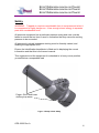
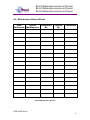
1
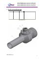
User Manual
Pump in Sub VAM HC
165-2222-HS0
OPS-2222 Rev A
Error! Reference source not found.
Error! Reference source not found.
Error! Reference source not found.
Revision History
Issue, Date
Rev A, 08 May 08
Remarks
Initial Issue
OPS-2222 Rev A
i
Error! Reference source not found.
Error! Reference source not found.
Error! Reference source not found.
Revision History ................................................................................................ i Safety .............................................................................................................. iii 1 Introduction ............................................................................................... 1 1.1 General .............................................................................................. 1 1.2 Product Identification ......................................................................... 1 2 Technical Specification ............................................................................. 1 3 Technical Description ............................................................................... 2 4 Operation .................................................................................................. 2 5 Job Planning ............................................................................................. 3 5.1 Pre Job .............................................................................................. 3 5.2 During Job ......................................................................................... 3 5.3 Post Job............................................................................................. 3 6 Maintenance ............................................................................................. 4 6.1 Introduction ........................................................................................ 4 6.2 Schedule............................................................................................ 4 6.2.1 Pre & Post Job............................................................................ 4 6.2.2 Yearly ......................................................................................... 4 6.2.3 Five Yearly ................................................................................. 4 6.3 Safety ................................................................................................ 4 6.4 Tools .................................................................................................. 5 6.5 Redress Procedure ............................................................................ 5 6.5.1 Dis-Assembly ............................................................................. 5 6.5.2 Re-Assembly .............................................................................. 5 6.5.3 Testing ........................................................................................ 5 6.6 Maintenance Record Sheet ............................................................... 6 7 Parts List and Drawings ............................................................................ 7 8 Troubleshooting ........................................................................................ 8 8.1 Leaking BX Seal ................................................................................ 8 8.2 Leaking 1502 Union ........................................................................... 8 8.3 Leaking VAM connection ................................................................... 8 Table 1:Technical Data .................................................................................... 1 Table 2:Maintenance Record ........................................................................... 6 Table 3:Parts List ............................................................................................. 7 Figure 1:Pump in Sub Safety .......................................................................... iii Figure 2:Flange Crossover .............................................................................. 2 OPS-2222 Rev A
ii
Error! Reference source not found.
Error! Reference source not found.
Error! Reference source not found.
Safety
WARNING: Trapped air requires considerable time to compress and when it
is compressed is highly dangerous. It has enough stored energy to separate
parts with considerable force.
All pressure equipment has a particular pressure rating and care must be
taken to ensure that no item is used in a situation that may cause its working
pressure to be exceeded.
All personnel involved in pressure testing must be formally trained, and
wearing the appropriate PPE.
Ensure the identification band/plate is fitted and is displaying the correct
information and that this is the correct manual.
This equipment and the equipment it is attached to is heavy never position
yourself below a suspended load
Finger, Glove and loose
clothing trap areas
Figure 1:Pump in Sub Safety
OPS-2222 Rev A
iii
Error! Reference source not found.
Error! Reference source not found.
Error! Reference source not found.
1 Introduction
1.1 General
The pump in sub is normally positioned between the wireline valve and the
wellhead. Its main function is to facilitate well control by pumping fluid when
the wireline valve is closed.
The Phuel pump in sub body is constructed with a 9-4 connection, a 5.5 VAM
HC connection and a side outlet sub which is a standard API BX flange that
allows suitable flow connections (2” 1502 weco type in this case) to be
attached.
This user manual serves as an introduction to the equipment and contains the
relevant specifications, operation, planning and maintenance instructions,
parts list and drawings.
1.2 Product Identification
Phuel products are identified by a unique serial number that facilitates full
product traceability. Each product is supplied with a documentation pack that
contains product certification and material/inspection reports. The serial
number is always etched on the surface of the product but can sometimes be
difficult to find or read after painting. A customer identification number is also
included to allow the customer to track the asset in their system.
A stainless steel band secures the nameplate tag that is stamped with the
information shown below. This tag should be located in the first instance to
ensure that this manual refers to the correct equipment.
PHUEL OIL TOOLS LTD
DESCRIPTION & SIZE
CUSTOMER ID No
PHUEL ID No 06-XXX-XX
MWP & SERVICE
TEST DATE
OPS-2222 Rev A
1
Error! Reference source not found.
Error! Reference source not found.
Error! Reference source not found.
2 Technical Specification
Part No
Connections
165-2144-HS0
9 – 4 Otis Type Connection
5.5 17# VAM HC pin
2’’ 1502 hammer lug union
Maximum Working Pressure
5000 Psi
Test Pressure
7500 Psi
Service
H2S
Weight
220 lbs/100 Kg
Overall Length
30’’/0.762M
Inner Diameter
4.82’’/0.122M
Table 1:Technical Data
OPS-2222 Rev A
1
Error! Reference source not found.
Error! Reference source not found.
Error! Reference source not found.
3 Technical Description
The pump in sub has been specially designed to act as a wellhead adapter
crossover from a 9-4 connection to a 5.5 VAM HC pin connection with a
WECO 2’’ 1502 side outlet.
The side outlet sub is a standard API BX flange that allows suitable flow
connections (2” 1502 weco type in this case) to be attached
Figure 2:Flange Crossover
4 Operation
Once the relevant valve has been connected to the WECO connection the
pump in sub is ready for connection between the wireline valve and the
wellhead to allow well control
The pump in sub can also be utilised to allow fluid sampling and/or inhibitor
injection.
OPS-2222 Rev A
2
Error! Reference source not found.
Error! Reference source not found.
Error! Reference source not found.
5 Job Planning
5.1 Pre Job
•
•
•
•
•
•
•
•
•
Ensure thread protectors are fitted
Check maintenance record sheet and ensure the equipment has been
maintained by competent personnel
Check all certification is in date
Confirm information band is fitted and correct
Ensure equipment is suitable for the maximum working pressures and
services involved
Ensure ‘O’ ring is seated correctly and there are no signs of damage
Ensure threads are clean
Inspect for signs of damage
Pressure test to 1.2x the maximum well pressure
5.2 During Job
•
Avoid excessive movement
5.3 Post Job
•
•
•
Inspect for signs of damage
Ensure threads are clean
Ensure thread protectors are fitted
OPS-2222 Rev A
3
Error! Reference source not found.
Error! Reference source not found.
Error! Reference source not found.
6 Maintenance
6.1 Introduction
Regular maintenance of the equipment using Phuel redress kits or Phuel
approved parts is essential to its continued safe operation. Ensure that the pre
and post job operating procedures are followed and that maintenance records
are kept.
6.2 Schedule
The maintenance schedule may be governed by international or company
standards and the following is considered to be the minimum requirements.
6.2.1 Pre & Post Job
Refer to Section 5.1 and Section 5.3 for details
6.2.2 Yearly
•
•
•
•
•
•
•
Disassemble Pump in Sub (see below) clean and degrease all
components
Inspect the condition of all sealing surfaces and surface coatings
Re-coat threads and sealing surfaces if necessary. If in doubt contact
Phuel Oil Tools Ltd
Regrease components
Re-assemble (see below)
Pressure test to maximum working pressure
Inspect paint work and repair as necessary
6.2.3 Five Yearly
•
•
•
Yearly Maintenance (plus the following)
Carry out 100% surface NDE on all surfaces
Pressure test to test pressure witnessed by certifying authority
6.3 Safety
•
•
•
•
Many of the components are heavy and should not be lifted without
lifting aids
Wear appropriate personal protective equipment
Do not over exert yourself while using torque wrenches. Use
appropriate mechanical advantages when available.
Ensure that all tools and equipment are in good condition and are
suitable for the intended use.
OPS-2222 Rev A
4
Error! Reference source not found.
Error! Reference source not found.
Error! Reference source not found.
6.4 Tools
The following tools are required:
• 50mm Spanner
• Wire Brush
• Torque wrench with 50mm socket (capable of 153lbft/207NM)
6.5 Redress Procedure
6.5.1 Dis-Assembly
•
•
•
•
•
Remove hex nuts
Remove flange crossover and seals
Degrease and clean all components
Inspect threads for damage
Fit thread protectors
6.5.2 Re-Assembly
•
•
•
•
•
Remove thread protectors
Inspect all threads for signs of damage and clean with wire brush
Insert studs into flange sub and tighten
Ensure top and bottom seal fitted to flange crossover
Fit flange crossover to flange sub (ensure bottom seal correctly
positioned) and tighten down into place with hex nuts to a torque of
153lbft (207NM)
6.5.3 Testing
All testing is to be carried out in the designated test area and by suitably
qualified personnel.
•
•
•
•
•
•
•
•
On completion of reassembly fit the appropriate test caps to either end
of the pump in sub and to flange crossover
Fill with test fluid and bleed off any air in the system
Apply a pressure of 500 psi and ensure pressure holds for a minimum
of 10 minutes
Increase pressure to 5,000 psi (Maximum Working Pressure), allow to
stabilise and maintain this pressure until it is evident there are no
apparent leaks.
Bleed off pressure, drain test fluid and dry
Remove test caps
Apply coating of de-watering solution to protect the bore and threads
Fit thread protectors
On completion of all maintenance ensure the maintenance record sheet
(Table 2) is completed
OPS-2222 Rev A
5
Error! Reference source not found.
Error! Reference source not found.
Error! Reference source not found.
6.6 Maintenance Record Sheet
Date
Type of
Performed
Performed Maintenance
By
Verified
By
Comments
Table 2:Maintenance Record
OPS-2222 Rev A
6
Error! Reference source not found.
Error! Reference source not found.
Error! Reference source not found.
7 Parts List and Drawings
ItemNumber ItemCommodity ItemQuantity
TitlePart
1
165-2187-480
1
PUMP IN SUB - BX152
2
950-2160-480
1
FLANGE CROSSOVER
3
950-2164-STL
1
API SEAL BX 152
4
HNC-0670-A2H
8
HEX NUT 3/4 UNC
5
165-2165-AB7
8
STUD 3/4-10 UN X 6" LONG
6
950-2167-N90
1
SEAL FOR FIG 1502 (ANSON)
7
910-2156-N66
1
9-4 ACME FEMALE PROTECTOR
Table 3:Parts List
OPS-2222 Rev A
7
Error! Reference source not found.
Error! Reference source not found.
Error! Reference source not found.
8 Troubleshooting
8.1 Leaking BX Seal
Try initially to increase the torque on the bolts but do not exceed 200 ft-lbs
If the leak continues then remove the flange sub and replace the BX seal.
Inspect the seal surface (outer angled face only) for any signs of pitting or
damage and correct if necessary before re-assembly.
8.2 Leaking 1502 Union
Replace the elastomeric seal. Check that the connection has not been
damaged prior to re-assembly.
8.3 Leaking VAM connection
Break out the connection and clean up the threads and inspect the seal
surface for any signs of damage. Re-apply thread dope and re-torque paying
attention to the torque curve. If the connection still leaks then it may be
necessary to cut back the connection. There is sufficient length for one full recuts on the pin. Consult an authorised VAM provider if required.
OPS-2222 Rev A
8