1
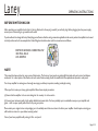
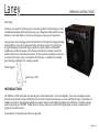
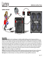
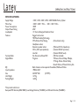
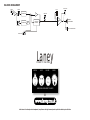
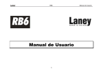
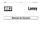
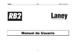
LX65D
USER MANUAL
IMPORTANT SAFETY INSTRUCTIONS
WARNING: When using electric products, basic cautions should always be followed, including the following.
1. Read all safety and operating instructions before using this product
2. The product should be powered by a three pin `grounded (or earthed) plug connected to a power socket with a grounded earth outlet.
3. All safety and operating instructions should be retained for future reference
4. Obey all cautions in the Operating instructions and on the back of the unit
5. All operating instructions should be followed
6. This product should not be used near water, i.e. a bathtub, sink, swimming pool, wet basement, etc.
7. This product should be located so that its position does not interfere with its proper ventilation. It should not be placed flat against a wall or placed in a built up enclosure that
will impede the flow of cooling air.
8. This product should not be placed near a source of heat such as stove, radiator, or another heat producing amplifier.
9. Connect only to a power supply of the type marker on the unit adjacent to the power supply cord.
10. Never break off the ground pin on a power supply cord.
11. Power supply cords should always be handled carefully. Never walk or place equipment on power supply cords. Periodically check cords for cuts or signs of stress, especially at
the plug and the point where the chord exits the unit.
12. The power supply cord should be unplugged when the unit is to be unused for long periods of time.
13. If this product is to be mounted in an equipment rack, rear support should be provided.
14. The user should allow easy access to any mains plug, mains coupler and mains switch used in conjunction with this unit thus making it readily operable.
15. Metal parts can be cleaned with a damp cloth. The vinyl covering used on some units can be cleaned with a damp cloth or ammonia based household cleaner if necessary.
Disconnect the unit from the power supply before cleaning.
16. Care should be taken so that objects do not fall and liquids are not spilled into the unit through any ventilation holes or openings. On no account place drinks on the unit.
17. A qualified service technician should check the unit if:
The power cord has been damaged
Anything has fallen or spilled into the unit
The unit does not appear to operate correctly
The unit has been dropped or the enclosure damaged.
18. The user should not attempt to service the equipment. All service work is done by a qualified service technician.
19. Exposure to extremely high noise levels may cause a permanent hearing gloss. Individuals vary considerably in susceptibility to noise induced hearing loss, but nearly everyone
will lose some hearing if exposed to sufficiently intense noise for a sufficient time. The U.S. Government's Occupational Safety and Health Administration (OSHA) has specified
the following permissible noise level exposure.
Duration Per Day In Hours
Sound Level dBA, slow response
8
90
6
92
4
95
3
97
2
100
1½
102
1
105
½
110
¼ or less
115
According to OSHA, any exposure in excess of the above permissible limits could result in some hearing loss. Ear plugs or protectors in the ear canals or over the ears must be
worn when operating this amplification system in order to prevent a permanent hearing loss if exposure exceeds the limits set forth above. To ensure against potentially dangerous
exposure to high sound pressure levels it is recommended that all persons exposed to equipment capable of producing high sound pressure levels such as this amplification system
be protected by hearing protectors while this unit is in operation.
SAVE THESE INSTRUCTIONS
Page 2 /12
Page 3 /12
Laney
OPERATING INSTRUCTIONS
BEFORE SWITCHING ON
After unpacking your amplifier check that it is factory fitted with a three pin 'grounded' (or earthed) plug. Before plugging into the power supply
ensure you are connecting to a grounded earth outlet.
If you should wish to change the factory fitted plug yourself, ensure that the wiring convention applicable to the country where the amplifier is to be used
is strictly conformed to. As an example in the United Kingdom the cable colour code for connections are as follows.
EARTH OR GROUND - GREEN/YELLOW
NEUTRAL - BLUE
LIVE - BROWN
NOTE
This manual has been written for easy access of information. The front and rear panels are graphically illustrated, with each control and feature
numbered. For a description of the function of each control feature, simply check the number with the explanations adjacent to each panel.
Your Laney amplifier has undergone a thorough two stage, pre-delivery inspection, involving actual play testing.
When you first receive your Laney guitar amplifier, follow these simple procedures:
(i) Ensure that the amplifier is the correct voltage for the country it is to be used in.
ii) Connect your instrument with a high quality shielded instrument cable. You have probably spent considerable money on your amplifier and
guitar - don’t use poor quality cable it won’t do your gear justice.
Please retain your original carton and packaging so in the unlikely event that some time in the future your amplifier should require servicing you
will be able to return it to your dealer securely packed.
Care of your Laney amplifier will prolong it's life.....and yours!
Page 4 /12
Laney
OPERATING INSTRUCTIONS
Dear Player,
Thank you very much for purchasing your new Laney product and becoming part of the
worldwide Laney family. Each and every Laney unit is designed and built with the utmost
attention to care and detail, so I trust yours will give you many years of enjoyment.
Laney products have a heritage which stretches back to 1967 when I first began building
valve amplifiers in my parent’s garage. Since then we have moved on from strength to
strength developing an extensive range of guitar, bass, public address and keyboard
amplification products along with a list of Laney endorsees that includes some of the
world’s most famous and respected musicians. At the same time we believe we have not
lost sight of the reason Laney was founded in the first place - a dedication to building
great sounding amplification for working musicians.
Warm Regards,
Lyndon Laney CEO
INTRODUCTION
The LX65D is a 65W open back twin channel guitar combo loaded with a 12 inch loudspeaker. It has two completely separate
channels, each with bass, mid and treble EQ controls and the drive channel features our custom XTS technology. It also features a
headphone socket for private listening; Extension speaker socket to drive additional cabinets and a CD/Line in socket should you
need to play along to a CD/MP3. Finally there is a line out socket and a built in 24bit digital signal processor complete with 15
programs and a level control.
An explanation of these features follows on pages 6-8.
Page 5 /12
Laney
1
2
3
OPERATING INSTRUCTIONS
4
5
6
8
9
10 11
12
13
14
15
16
17
18
20
7
19
FRONT PANEL CONTROLS
1 This socket should be used for connecting your instrument to the amplifier. Only use a good quality screened cable.
2
Controls the volume level of the clean channel.
3
Controls the amount of bass or bottom end present on the clean channel.
4
Controls the amount of mid present on the clean channel.
5
Controls the amount of treble present on the clean channel.
6
Switch in to activate the overdrive ‘Crunch’ channel. When active, control the amount of distortion with
volume with
7
Indicates that the drive channel is active.
8
Controls the crunch channel gain, low down for classic rock and blues, higher up for hard rock and metal.... the higher you go
the more Extreme it gets. Use in conjunction with to get the overall level balanced how you want it.
9
Controls the overall level on the drive channel. Use with
8
and the overall
9
9
8
eXtreme Tone Shaping. This applies a scooped mid tone shape to the drive channel and boosts certain key frequencies for a
10 unique sound.
11 Controls the amount of bass or bottom end present on the drive channel.
Page 6 /12
Laney
OPERATING INSTRUCTIONS
12 Controls the amount of mid present on the drive channel.
13 Controls the amount of treble present on the drive channel.
14 Controls the amount of signal returned from the onboard effects processor.
15 The onboard digital effects have been custom designed by Laney to complement the LX65D with a choice of Delays, Flange,
Rotary, Octave Down, Chorus, Reverb and combinations of these. Select your chosen effect here, and control the level with
14
16 Fancy playing along with a backing track? Connect your CD/MP3 player here.
Connect a Laney FS2 footswitch here to enable remote switching for the channel and reverb/FX. Note: Drive channel must be
17 enabled for channel switching via footswitch to function.
18 Line out socket to connect to a recording device or another amplifier/PA etc.
19
When ‘on’ indicates that power is connected to the unit and it is ready to go.
(Always switch off and disconnect the power cord when not in use)
20 Main power switch for the unit.
Page 7 /12
Laney
24
OPERATING INSTRUCTIONS
25
26
27
28
24 Power inlet socket. Connect to your power source. Make sure the specified voltage is correct for your country!
25 This drawer contains the main safety fuse for the unit.
USE ONLY THE CORRECT SIZE AND RATING OF FUSE AS SPECIFIED ON THE PANEL
The mains fuse ratings are detailed in the specs section at the rear of this manual
26 Displays the model number, power requirements and serial number of the unit.
27 Connect an extension loudspeaker cabinet here, the internal loudspeaker is left connected. The impedance of the extension
cabinet must not be less than 8 Ohms. Connecting cabinets that have a lower impedance than 8 Ohms will result in the
amplifier overheating. Continual use in this manner may cause permanent damage.
28 Don’t want to wake your neighbours? Connect your headphones here. The internal loudspeaker is automatically switched off.
Page 8 /12
Laney
OPERATING INSTRUCTIONS
QUICK START SETTINGS
CLEAN SETTINGS
CLEAN EQUALISATION
DRIVE
DRIVE EQUALISATION
EFFECTS
LX65D
1
0
OUT
INPUT
VOLUME
BASS
MID
TREBLE
CRUNCH
VOLUME
XTS
BASS
MID
TREBLE
LEVEL
EFFECTS
CD/LINE IN FOOTSWITCH LINE OUT
POWER
BLUES SETTINGS
CLEAN EQUALISATION
DRIVE
DRIVE EQUALISATION
EFFECTS
LX65D
1
0
IN
INPUT
VOLUME
BASS
MID
TREBLE
CRUNCH
VOLUME
XTS
BASS
MID
TREBLE
LEVEL
EFFECTS
CD/LINE IN FOOTSWITCH LINE OUT
POWER
ROCK SETTINGS
CLEAN EQUALISATION
DRIVE
DRIVE EQUALISATION
EFFECTS
LX65D
1
0
IN
INPUT
VOLUME
BASS
MID
TREBLE
CRUNCH
VOLUME
XTS
BASS
MID
TREBLE
LEVEL
EFFECTS
CD/LINE IN FOOTSWITCH LINE OUT
POWER
EXTREME/METAL SETTINGS
CLEAN EQUALISATION
DRIVE
DRIVE EQUALISATION
EFFECTS
LX65D
1
IN
INPUT
VOLUME
BASS
MID
TREBLE
0
IN
CRUNCH
VOLUME
XTS
BASS
MID
TREBLE
LEVEL
EFFECTS
CD/LINE IN FOOTSWITCH LINE OUT
POWER
Page 9 /12
Laney
OPERATING INSTRUCTIONS
SAMPLE SYSTEM
Laney
Power To The Music
RB115
LX412S
Model
Power Rating 300W Program
Serial Number:
SAMPLE
DESIGNED IN THE UK BY LANEY
www.laney.co.uk
Input
8 Ohms
Link
General Notes
Amplifier connection: In order to avoid damage, it is advisable to establish and follow a pattern for turning on and off your
equipment. With all system parts connected, turn on source equipment, tape decks, cd players, mixers, effects processors etc. BEFORE
turning on your guitar amplifier. Many products have large transient surges at turn on and off which can cause damage to your speakers.
By turning on your guitar amplifier LAST and making sure its Volume controls are set to minimum any transients from other equipment
will not reach your loudspeakers. Wait until all system parts have stabilised; usually a couple of seconds. Similarly when turning off your
system always turn down the Volume controls on your guitar amplifier and then turn off its power before turning off other equipment.
Cables: never use shielded or microphone cable for any speaker connections as this will not be substantial enough to handle the
amplifier load and could cause damage to your amplifier system.
Caution: These professional loudspeaker systems are capable of generating very high sound pressure levels. Use care with placement
and operation to avoid exposure to excessive levels that can cause permanent hearing damage. (Refer to guidelines on page 2)
Servicing: The user should not attempt to service these products. Refer all servicing to qualified service personnel.
Page 10 /12
Laney
SPECIFICATIONS
Supply Voltage
Mains Fuse
Power Consumption
Output Power Rating
Loudspeaker
Features
Footswitchable
Digital Effects
EQ
Input Impedance
Size
Unit Weight
Packing Weight
OPERATING INSTRUCTIONS
~100V, ~120V, ~220V, ~230V, ~240V 50/60Hz Factory Option
~220V>~240V = T1A L. ~100>~120V = T2A L
100W
65W
12” Custom Designed Celestion Driver
Rugged construction
TEC Tube Emulating Technology
XTS eXtreme Tone Shaping
(Drive channel only)
Headphone socket,
Extension speaker socket
(Minimum 8 Ohm Impedance)
CD In (10K Input impedance)
(Nominal 300mV Input level)
Line Out
(Nominal 300mV Level)
Yes, Channel and Reverb/FX
(FS2 Not included)
Programs:
2*Chorus, Chorus+Delay, 4*Delays,
2* Flange, Octave, Octave+Delay,
Reverb+Chorus, 2*Reverb, Rotary Sim.
Both channels contain separate Passive Bass, Middle and Treble
1MOhm/47pF
456*497*258
(H*W*D)
14.7 Kg
16.0 Kg
This product conforms to:
European EMC directive(2004/108/EC), Low Voltage Directive (72/23/EEC) and CE mark Directive (93/68/EEC)
Page 11 /12
BLOCK DIAGRAM
INPUT
HEADPHONES
CD IN
CLEAN
EQ SECTION
EQ SECTION
LINE OUT
XTS
POWER
AMP
REVERB /
EFFECTS
INTERNAL
LOUDSPEAKER
DRIVE
EXT. LOUDSPEAKER
FOOTSWITCH
Laney
POWER TO THE MUSIC
METAL
BLUES
JAZZ
ROCK
AMPICONS ARE HERE TO HELP!
@
In the interest of continued product development, Laney Reserves the right to amend product specification without prior notification.