1
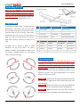
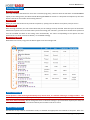
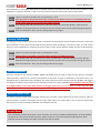
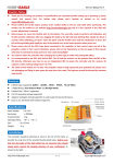
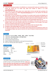
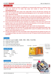
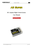
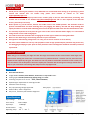
A3 User Manual V1.0 Caution Notes Thank you for choosing our products. If any difficulties are encountered while setting up or operating it, please consult this manual first. For further help, please don’t hesitate to contact us via email [email protected]. Please confirm the 13-bit unique product series number (S/N) on the bar code label when purchasing. This number can be verified at our website http://www.hobbyeagle.com and it is also required in the after-sale service, please keep it securely! Before power on, put the aileron, elevator and rudder sticks in the middle position. The controller needs to perform self-calibration and stick centering after you plugging the battery, the LED will keep blinking Blue rapidly for about 3 seconds while calibrating, don’t move the plane and the sticks until the initialization is done. It’s extremely important to verify that the gyro reacts in the correct direction before flight, or it could lead to losing control or even crash during flight! You need to restart the controller after changing the receiver type to make new setting take effect. Never use the delta-wing or V-tail mixing functions of your transmitter. A3 supports a wide working voltage from 5 to 7.4V, you can use HV receiver or servo directly. The radio control models are not toys. The propellers rotate at high speed and pose potential risk, please carry out debugging and flying in open space far away from the crowd. The beginner should be directed by someone experienced. About D/R and EXPO When the gyro is activated, you might see that the range of movement of the servo become much larger than before when moving the sticks. This is normal but not a problem because a rotation rate set point has been applied to the outputs by the gyro. The sticks are not only used to control the movement of the surface, but also the rotation rate of the plane in that axis. Anyway the controller will not change the settings of dual rate or expo in your transmitter. The settings will always work in any flight mode. Features One-click Auto Hover! 4 Flight Modes: Normal, Auto-balance, Auto-hover and Gyro Off modes. 3 Wing Types: Standard, Delta-wing (Flying-wing) and V-tail. 3 working frequencies for servos:50Hz, 125Hz and 250Hz; Separated gain adjustment for each flight mode. Automatic stick centering. HV (7.4) operating voltage supported. Futaba S.Bus / S.Bus 2 supported. Easy to use, extremely well-suited to beginners. Specifications Input Voltage: 5 to 7.4V Servo Travel: 1520 ± 500μs Gyroscope: ± 2000dps Accelerometer: ± 4g Operating Temp: -40 ℃ ~ 85 ℃ http://www.hobbyeagle.com 1/5 [email protected] A3 User Manual V1.0 Size: 43 × 27mm Weight: 11 g Installation The controller must be firmly mounted on the platform of the airframe by using the provided double-sided tape, as close to the CG as possible. The controller can be attached flat or upright. However, the servo connector pins must always point toward the rear of the plane (the shorter side with the setting button must always point toward the heading direction). There’re 4 mounting orientations supported, as shown below. Connection Standard Receiver If a standard receiver is being used, you just need to connect the corresponding channels to the pins AIL, ELE, RUD, MOD and GAIN using the included receiver wires. The aileron, elevator and rudder should be always connected or it could not work. The MOD is used for flight mode control, if you don’t connect it the flight mode will be set to normal as the default. The GAIN is used to adjust the master gain remotely. If you don’t connect it the gain will be set to 100% all the time as the default. Wiring is as shown in the figure below. Futaba S.Bus The Futaba’s S.Bus/S.Bus 2 is also supported by A3. Because the S.Bus is a single-line solution all channels are transmitted via one single line you need to establish the first 6 channels in the correct order in your transmitter before use. Here we use a R7008SB receiver as an example because it supports both S.Bus and S.Bus 2. You need to change the mode for the R7008SB before using its S.Bus outputs, please refer to the manual of it. http://www.hobbyeagle.com 2/5 [email protected] A3 User Manual V1.0 Delta-wing & V-tail Never use the delta-wing and V-tail mixing functions of your transmitter, all you need is to choose a single 4-channel fixed-wing model in your radio any time. The right figure shows the servo connections for a delta-wing or V-tail. Flight Modes A3 Supports 4 flight modes, including Normal, Auto-balance , Auto-hover and Gyro Off mode. You can switch them using a 3-way switch on the transmitter. But if you are using a 2-way switch instead then you can only use 2 of them during flight. The color of the LED shows you that the Flight Mode Colors of LED Descriptions 1 Normal Mode Blue Gyro rate mode 2 Auto-balance Red Self-balance Mode 3 Auto-hover Blue & Red Self-hover Mode 4 Gyro Off Mode Off Gyro deactivated mode flight mode currently selected, as shown to the Modes Position-1 Position-2 Position-3 1 Mode-1 Normal Auto-balance Auto-hover A3 allows you to choose 4 kinds of mode 2 Mode-2 Normal Gyro Off Auto-balance definitions for the 3-way switch, the factory 3 Mode-3 Normal Gyro Off Auto-hover default is Mode-1 (Normal-Balance-Hover). You 4 Mode-4 Auto-balance Gyro Off Auto-hover right. can change it through function 7 in the setting menu, as shown to the right. Gyro Directions It’s extremely important to verify that the gyros of all channels are reacting in the correct direction before flight, otherwise it could lead to losing control or even crash during a flight! To perform the examination, power on the plane, pick it up and check by following the steps in the figures on the left. If the gyro compensates in an incorrect direction, reverse it at once! Aileron Quickly move the right wing downward around the roll axis. The right aileron surface should flap down and the left flap up. Elevator Quickly move the nose of the plane downward around the pitch axis. The elevator surface should flap up. Rudder Quickly move the nose of the plane to the left around the yaw axis. The rudder surface should flap right. http://www.hobbyeagle.com 3/5 [email protected] A3 User Manual V1.0 Setting Methods Setting Menu Press and hold down the button for more than 2 seconds (long press), release it when the LED starts to blink Blue&Red rapidly. In the setting menu, the LED should be blinking Blue&Red for N times in a loop with the sequence by the chart below. N stands for the number of the setting function. Functions When you reach the function that you wish to operate in, quickly press the button once (short press) to enter it. Parameters After entering a function, the color of the LED shows you the settings currently selected. Each short press of the button advances the option to the next value. When you finish making your selections, just wait for 5 seconds then system will save the modified and back to the setting menu automatically. The colors corresponding to the options for each parameter are as shown in the chart below. (* is the default setting). Exit Setting Mode When back to the menu, long press the button again to exit the setting mode. Stick Centering A3 will perform a stick centering automatically every time it starts, so a manual centering is no longer needed. You just need to keep all the sticks ( except throttle) in their middle position before power on the controller, and don’t move them while initializing. You can change the trims or sub-trims settings in your transmitter anytime you need, the new center positions will be relearned and saved by the controller next time it starts. Level Calibration This function is only used for auto-balance mode, to establish the appropriate level attitude of the plane. After firsthttp://www.hobbyeagle.com 4/5 [email protected] A3 User Manual V1.0 time installation, or if the plane drops down or up when switch to auto-balance mode, you will need to perform a level calibration to make the controller re-learn a new correct level reference. Follow the steps as shown below. Step 1 Power on the plane and wait until the initialization is done. Step 2 Place the plane on the ground horizontally. In order to get a better result, it is recommended that you would need to make the nose of the plane slightly upwards. Step 3 Enter setting mode and select function 9, when the LED starts to blink Blue & Red, it means that the calibration is being performed. It will take you about 5 seconds, don’t move the plane during this period. Step 4 After the calibration is done, exit the setting mode and fly it again. Vertical Calibration This function is only used for auto-hover mode, to establish the appropriate vertical attitude of the plane. After first time installation or if the plane cannot hold hovering correctly when operating in auto-hover mode, you will need to perform a vertical calibration to make the controller re-learn a new hovering attitude. Follow the steps as shown below. Step 1 Power on the plane and wait until the initialization is done. Step 2 Pick the plane up and make it vertically, both in elevator and rudder directions. Step 3 Enter setting mode and select function 10, when the LED starts to blink Blue & Red, it means that the calibration is being performed. It will take you about 5 seconds, don’t move the plane during this period. Step 4 After the calibration is done, exit the setting mode and fly it again. Gain Adjustment There are 3 knobs on the controller (GAIN1, GAIN2 and GAIN3), they are used to adjust the gyro gain for each flight mode separately. Clockwise for increase, anticlockwise for decrease. The gain is affected by many factors there is no standard answer to that how much it should be. You need to fine-tune to get the best result during flights. We suggest you always start with a lower volume for the first flight and then increase it gradually. The normal gain will take effect in all flight modes, it’s the most basic feature of the gyro, don’t turn it to 0% anyway. In order to get the best performance in auto-hover mode, you could try to turn the hover gain on full volume. Remote Master Gain The GAIN is used to control the master gain remotely. You can make a linear adjustment by using a knob or slider on your transmitter, or make a 3-level gain control using a 3-way switch. The master gain is just an optional channel that the controller can still work properly without connecting this channel. Device Reset Press and hold the button while power on the controller, you will see both Blue and Red LED turn on. Keep holding the button for more than 4 seconds and don’t release it until you see the LED flashes Blue & Red twice, which indicates that all the settings have been restored to the factory default. http://www.hobbyeagle.com 5/5 [email protected]