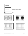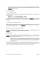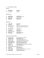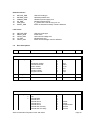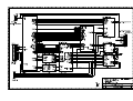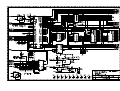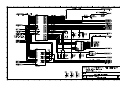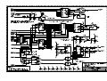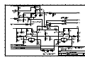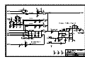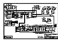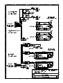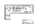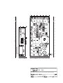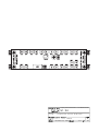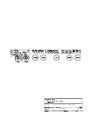
1
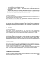
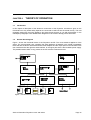
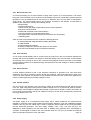
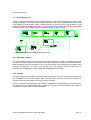
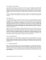
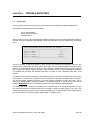
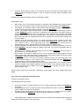
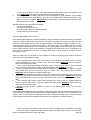
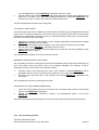
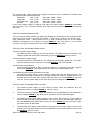
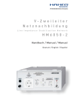
SERVICE INFORMATION
PHYACTION 740 & 790 SERIES
Copyright© Uniphy BV 1995
Phyaction® is a registered trademark of Uniphy BV
Art. Code 93007916.5
Phyaction is manufactured in The Netherlands by Uniphy BV
P.O.box 558, NL-5600 AN Eindhoven, the Netherlands
Tel. +31-499-471771 Fax +31-499-474734
GENERAL INFORMATION .................................................................. 1
Introduction............................................................................................................................ 1
Safety aspects ....................................................................................................................... 1
Installation.............................................................................................................................. 2
Description of the controls .................................................................................................. 3
Technical specifications ...................................................................................................... 6
Explanation of symbols........................................................................................................ 9
Photos of the current waveforms ...................................................................................... 14
CHAPTER 1
1.1
1.2
1.3
1.4
1.5
1.6
1.7
THEORY OF OPERATION ..................................................................
Introduction...........................................................................................................................
General block diagram ........................................................................................................
Electrotherapy unit ..............................................................................................................
Ultrasound therapy unit ......................................................................................................
Infrared laser unit .................................................................................................................
CHAPTER 2
2.1
2.2
2.3
2.4
2.5
CHAPTER 3
3.1
PERFORMANCE CHECK .................................................................... 23
Safety inspection ................................................................................................................. 23
ADJUSTMENT PROCEDURES ......................................................
Introduction...........................................................................................................................
Adjustment of the dose potentiometer guard circuit......................................................
Adjustment of the laser power measuring cell ................................................................
25
25
25
25
TROUBLE SHOOTING ...........................................................................
Introduction...........................................................................................................................
Error shutdown procedure .................................................................................................
General test description......................................................................................................
Error numbers summary.....................................................................................................
Error descriptions ................................................................................................................
26
26
27
27
33
34
CHAPTER 4
4.1
4.2
4.3
CHAPTER 5
5.1
5.2
5.3
5.4
5.5
15
15
15
17
18
20
CHAPTER 6
CIRCUIT DIAGRAMS ............................................................................... 39
CHAPTER 1
1.1
GENERAL INFORMATION
Introduction
The Phyaction 796 is an appliance for ultrasound therapy, electrotherapy (1 channel medium frequency
or TENS), combination therapy (MF & US) and laser therapy. The Phyaction 792 is the same as the 796,
except that it can't support laser therapy. The Phyaction 793 is the same as the Phyaction 792, except it
also contains rectified currents for electrotherapy. The Phyaction 740 can only be used for laser therapy.
In this manual the Phyaction 796 is described because it is the most extensive model in the series and
the Phyaction 793 for the rectified currents.
In this chapter the important features from the users manual for service personnel are listed. In the next
chapter the theory of operation will be explained. In chapter 3 is described how service personnel can
check the operation of a 796 and in chapter 4 the adjustments which can be executed by service
personnel are explained. The next chapter contains information which could be very useful for trouble
shooting such as the description of the automatic self test and a list of the error numbers. The schematic
diagrams are in chapter 6, the spare parts list in chapter 7 and a list of all the modifications is in the last
chapter.
1.2
Safety aspects
1.2.1 Electrical safety
The equipment can only be used in areas with provisions in accordance with current statutory
requirements. Pay particular attention to the use of protective earth, otherwise the patient leakage current
can rise above the permitted limit for type B equipment.
1.2.2 Explosion safety
The equipment is not suitable for use in areas where flammable gasses or vapours are present.
Therefore, remove the mains plug from the socket before the area in which the equipment is located is
disinfected, since some disinfection solutions evaporate and subsequently form an explosive mixture.
1.2.3 Operational safety
-
-
Using the equipment in the vicinity of short wave or microwave equipment can influence the output
of the unit. Using this equipment when high frequency surgical equipment is connected to the patient
at the same time can result in burning under the electrodes.
Patients who have electrical implants (i.e. pacemaker) may only be treated following medical
advice.
Laser beams are dangerous for the eyes. You must ensure that the laser beams do not reach the
eyes. In cases where the risk of laser beams reaching the eyes is increased, for example when the
patient is receiving treatment to the face, then he/she should wear safety glasses. Also, when you
are holding the probe at some distance from the skin and there is the possibility of the beam
reflecting into the eyes, the patient and the therapist should wear glasses. For other treatment it is
advised to wear glasses.
The equipment is not suitable for use in damp areas.
Service Information Phyaction 740 & 790-series
Page 1
-
A warning sign should be hung on the door to the area in which laser therapy is being applied. The
sign should include the laser warning symbol and the text "Attention, laser light is used in the area".
The equipment may not be disinfected or sterilized.
The equipment contains a number of safety systems which operate independently of the
microprocessor.
When the safety system detects a fault during electrotherapy the delivery of current is interrupted
within a few milliseconds and it is impossible to perform treatment using the equipment. The safety of
the patient is therefore guaranteed. Whenever the equipment is switched on (using the main switch)
the microprocessor checks the entire safety system for correct operation.
1.2.4 Use of the appliance
The equipment and accessories should only be used by authorized personnel and in accordance with all
instructions included in these operating instructions.
The Phyaction 796 is only to be used for laser, ultrasound and/or electrotherapy. The Phyaction 792 is
only to be used for ultrasound and/or electrotherapy.
1.2.5 Radio interference suppression and electromagnetic compatibility
This equipment meets the guidelines for ISM equipment relating to electromagnetic compatibility and is
radio interference suppressed according to VDE 0871-B. Also see paragraph 1.2.3 Operational safety,
concerning the use of the equipment in the vicinity of short wave and microwave equipment.
1.3
Installation
1.3.1 Incoming inspection
Check that the equipment, ultrasound head(s) and laser probe(s) have not been damaged during
transportation and that the accessories are intact and complete (see chapter 21 ACCESSORIES of the
INSTRUCTIONS FOR USE). In the event of damage and/or defect you should inform your supplier.
1.3.2 Mains voltage
Your equipment is suitable for a nominal voltage of 110, 120, 220 or 240 Volt AC, 50-60 Hz. Indicated on
the rear of the equipment will be the voltage for which it has been wired. You can not alter this yourself.
Carefully check this data before you place the mains plug in the socket. The mains input is on the rear of
the equipment.
1.3.3 Functional test
During production the equipment is tested for electrical safety. Whenever the equipment is switched on,
the processor performs an extensive test to ensure that the equipment is operating correctly. In addition
you must check whether the display and the indicator lamps are operating correctly. If this is not the
case, then you must not use the equipment and you must contact your supplier.
If you can not read or if it is difficult to read the display, then press the right hand blue button and the
black ¿ button in order to darken the text or the black À button if you want to make the text lighter.
1.3.4 Selecting the operating language
You have the possibility to change the operating language by depressing the left hand yellow button and
Service Information Phyaction 740 & 790-series
Page 2
holding it down until the STANDARD SETTINGS menu appears. You have the choice from various
languages. Once selected, the equipment will use the language you have chosen.
1.3.5 Location and transportation
The equipment must be set up horizontally and stable. You must ensure that the perforated sections on
both sides of the casing are not covered up, thus hindering air circulation. Objects must not be placed on
the equipment and you must ensure that no liquid enters the equipment.
1.4
Description of the controls
On the last page of this service manual you will find an illustration of the equipment and the accessories.
1.4.1 Display
The display1 consists of separate picture elements which are controlled by a processor so that you can
see text and figures. When you are performing a treatment, the display shows all of the information you
require:
Top left is the name of the therapy form. For combination therapy you will find the names of the
two selected therapy forms here.
The central section provides information about the parameters.
The right-hand section provides information about the output current during electrotherapy, the
power emitted during ultrasound therapy and the energy emitted at that moment for laser therapy.
For ultrasound combination therapy with a current form, the right-hand section provides the
information mentioned above for both selected forms of therapy. Additionally, this section also
provides information regarding the therapy time.
The bottom line of the display shows the functions of the blue buttons.
Lay out of the display
1.4.2 Signal lights
In the centre of the panel you will find three coloured lights:
The green lamp2 shows that the equipment is connected to the mains and is switched on.
The yellow lamp3 provides information during electrotherapy regarding stimulation. For medium
frequency surge current it shows the stimulus time, for current forms with frequency modulation it
shows the time during which the frequency is low, in other words, when the current form is the
most sensitive.
The red lamp4 illuminates when the safety system has detected a fault that causes the equipment
to be non-operational. A message appears on the display.
Service Information Phyaction 740 & 790-series
Page 3
The yellow lamps5 beside the output connectors for the ultrasound heads and the laser probes illuminate
respectively as soon as ultrasound or infra-red power is emitted. The yellow lamp beside the current
output6 illuminates as soon as 5mAeff of current is exceeded.
1.4.3 Infra-red sensor
Infra-red laser beams are invisible. In order to check that the laser probe is operating correctly, a sensor7
is built in. This sensor is located to the right above the current output socket. Using application no. 903
the infra-red laser power can be tested. If the laser probe is held in front of the sensor, the measured
peak power will appear on the display. We advise you to perform such a measurement periodically, for
example monthly. When performing a treatment using laser therapy, the infra-red sensor can be used to
test whether laser energy is being emitted through the probe.
1.4.4 Knobs
On the front and to the right there are three potentiometers. When you turn these knobs fully anticlockwise, you will detect a click indicating that they are in the zero position. From the top to the bottom
the knobs have the following functions:
Using the top knob8 you can adjust the laser energy in Joules. The treatment time changes
automatically.
The middle knob9 is used to adjust the peak intensity in Watt/cm2 for ultrasound.
The bottom knob10 is the dose regulator for electrotherapy.
1.4.5 Push-buttons
-
The blue buttons11 have a function which is different for each program and each menu. The display
indicates clearly whether the buttons have a function and, if so, which function.
The black buttons ¿ or À12 are used to increase or decrease the value of a parameter which you
have previously selected.
The left hand yellow button13 is used to return to the main menu. If you hold down this button for a
few seconds you will arrive in a special menu STANDARD SETTINGS.
Once you have selected a program, the right hand yellow button14 quickly and easily provides you
with further options of the selected program. Using this button you can call up the applications from
the main menu.
Using the green button15 you can call up the special memory function. You can store, retrieve and
change 250 different treatments.
1.4.6 Output connectors and sockets on the front
The equipment is fitted with a number of connectors for the following functions:
The two connectors16 on the far left are used to connect the laser probe(s). It does not matter to
which of the two connectors the laser probe(s) is/are connected.
The two middle connectors17 are for connecting the ultrasound head(s). Here too it makes no
difference to which connector the head(s) is/are connected. You can connect two heads at the same
time.
The two safety sockets18 on the far right are used for connecting the electrode cables during
electrotherapy. For combination therapy you can only use the socket on the far right, since in this
case the other socket is without current. In this case the metal treatment surface of the ultrasound
head forms the other electrode.
1.4.7 Key switch
When you want to switch on a program utilizing laser, you should turn the key switch19 to the right. To
Service Information Phyaction 740 & 790-series
Page 4
switch off, turn the key to the left. To prevent the use of laser by unauthorized personnel, you should
remove the key from the equipment when it is not being used.
1.4.8 Operating elements on the rear of the equipment
The following operating elements are located on the rear of the equipment:
Mains input with main switch20.
Fuse holder21 between the mains input and the main switch. The rating of the fuse to be used is
stated on the rear of the unit.
The serial in- and output22. These are for future extensions.
Connector for potential mains equalisation23.
Label with equipment data24.
1.4.9 Laser probes
Various laser probes25 can be supplied. When you have two probes, these can be connected to your
equipment at the same time. Using a blue button you select from the program which probe you wish to
use. A green lamp26 then illuminates on the selected probe. On the probe is a knob27, which has to be
pressed to allow laser light to be emitted. When laser light is being emitted, the yellow lamp28 on the
probe illuminates. For reasons of patient safety and correct operation of the equipment, the connection of
probes other than those supplied by Uniphy is not permitted.
If in doubt about the proper operation of your laser probe, you can check this by using technical
application no. 903.
Looking into the probe when laser light is being emitted can seriously damage the eyes.
Therefore, never look into the laser probe and never point it towards the eyes.
1.4.10 Ultrasound treatment heads
You have the choice of three ultrasound heads29 with an ERA (Effective Radiation Area) of respectively 1,
4 or 10 cm2. For each treatment head a multi-functional head holder30 is supplied. With each treatment
head both 1 and 3 MHz ultrasound can be given. Two treatment heads can be connected to the
equipment at the same time, provided the treatment heads do not have the same format. Using one of
the blue buttons you select which of the two heads you wish to use. A green lamp31 illuminates on the
treatment head as soon as it has been selected and a red lamp23 illuminates when the surface of the
head makes insufficient contact with the patient. The ultrasound power is then automatically adjusted
back so that overheating and subsequent wear of the treatment head is prevented. During insufficient
contact the treatment time also stops and when contact is made it continues. In this way the set time is
actually utilized.
Before using a new treatment head a one-off operation should be performed, using technical application
no. 902, to tune your equipment to the treatment head.
1.5
Technical specifications
The Phyaction 790-series consists of two models: the Phyaction 792 and 796. The same specifications
for the Phyaction 796 also apply to the Phyaction 792, however, the 792 model is not fitted with an IRlaser.
Service Information Phyaction 740 & 790-series
Page 5
1.5.1 Ultrasound therapy
General:
Duty-cycle adjustable from 1:1 up to 1:15
Power setting using potentiometer
The unit calculates the total effective power and displays it on the LCD
Option to tune the ultrasound head to the unit using a special program
Option of combination therapy using one of the 4 options with electrotherapy current forms
For each head a green lamp illuminates as soon as the head is selected
During insufficient contact the ultrasound power is automatically reduced and a red lamp
illuminates on the head. The timer stops
Reflected waves are partially absorbed by the heads to avoid intensity peaks
Specifications small treatment head (model 291):
Frequencies:
0.8 MHz and 3.3 MHz
BNR at 0.8 MHz:
<5
BNR at 3.3 MHz:
<4
ERA:
1 cm2
Output power:
0 - 1.5 W/cm2 at 3.3 MHz continuous
0 - 2 W/cm2 at 0.8 MHz continuous
0 - 3 W/cm2 at 0.8 and 3.3 MHz pulsed
Specifications large treatment head (model 292):
Frequencies:
0.8 MHz and 3.3 MHz
BNR at 0.8 MHz:
<5
BNR at 3.3 MHz:
<4
ERA:
4 cm2
Output power:
0 - 1.5 W/cm2 at 3.3 MHz continuous
0 - 2 W/cm2 at 0.8 MHz continuous
0 - 3 W/cm2 at 0.8 and 3.3 MHz pulsed
Specifications extra large treatment head (model 293):
Frequencies:
1.0 MHz and 3.4 MHz
BNR at 1.0 MHz:
<5
BNR at 3.4 MHz:
<4
ERA:
10 cm2
Output power:
0 - 1 W/cm2 at 1.0 and 3.4 MHz continuous
0 - 1.5 W/cm2 at 1.0 and 3.4 MHz pulsed
1.5.2 Laser therapy
General:
Pulse repetition frequency 2 - 5000 Hz
Energy adjustable with potentiometer
Operating distance 0 - 5 cm (for energy density calculation)
Conversion of energy to energy density with given operating distance and calculation of treatment
area
Test eye for checking power of the laser
A green lamp illuminates when probe is selected and yellow lamp when probe emits energy
Prior to accessing the laser program the key on the unit should be turned
Specifications 15 W probe (model 241):
Peak power:
minimum 12 W, maximum 18 W
Max. average power:
12 mW
Wave length:
904 nm (infrared)
Laser class:
3B
Service Information Phyaction 740 & 790-series
Page 6
-
Pulse duration:
Beam diameter:
Divergence angle:
Dimensions:
150 ns
2.5 mm
approx. 20 degrees
diameter 2.5 cm, length 21 cm
Specifications 25 W probe (model 242):
Peak power:
minimum 22 W, maximum 30 W
Max. average power:
25 mW
Wave length:
904 nm (infrared)
Laser class:
3B
Pulse duration:
200 ns
Beam diameter:
4.0 mm
Divergence angle:
approx. 32 degrees
Dimensions:
diameter 2.5 cm, length 21 cm
Specifications 4x18 W probe (model 245):
Peak power per diode:
minimum 16 W, maximum 22 W
Max. average power:
60 mW
Wave length:
904 nm (infrared)
Laser class:
3B
Pulse duration:
150 ns
Beam diameter:
4 x 2.5 mm
Homogeneous intensity:
from appr. 3 cm from the probe
Divergence angle:
approx. 20 degrees
Dimensions:
diameter 4 cm, length 22 cm
1.5.3 Electrotherapy
Parameters two-pole interferential current:
Carrier wave frequency:
4000 Hz
AMF:
1 - 200 Hz
Spectrum:
0 - 200 Hz
Time:
1 - 100 s
Contour:
1 - 100%
Output current:
140 mApeak maximum at 500 Ohm
Parameters, medium frequency surge current:
Carrier wave frequency:
4000 Hz
AMF:
1 - 200 Hz
Stimulation time:
1 - 100 s
Pause:
1 - 100 s
Surge:
1 - 100%
Output current:
140 mApeak maximum at 500 Ohm
Choose from automatic or manual stimulation using pulsator
Parameters TENS current, continuous:
Pulse time:
10 - 300 µs
Pulse frequency:
1 - 500 Hz
Spectrum:
0 - 200 Hz
Time:
1 - 100 s
Contour:
1 - 100%
Output current:
140 mApeak at 500 Ohm
Pulse form:
asymmetrical
Parameters TENS current, burst:
Pulse time:
Pulse frequency:
10 - 300 µs
80 - 500 Hz
Service Information Phyaction 740 & 790-series
Page 7
-
Burst frequency:
Number of pulses per burst:
Output current:
Pulse form:
1 - 10 Hz
5
140 mApeak maximum at 500 Ohm
asymmetrical
TENS current, surge (Phyaction 793 only):
Pulse time:
10 - 300 µs
Pulse frequency:
1 - 500 Hz
Train duration:
1 - 100 s
Train interval:
1 - 100 s
Surge:
1 - 100%
Output current:
140 mApeak at 500 Ohm (at a pulse time up to 100 µs)
Pulse form:
asymmetrical
Continuous galvanic current (Phyaction 793 only):
Output current:
80 mApeak at 500 Ohm
Interrupted galvanic current, rectangular or triangular pulse (Phyaction 793 only):
Pulse time:
0.1 - 1000 ms
Pause time:
2 - 9999 ms
Output current:
80 mApeak at 500 Ohm
Faradic current, rectangular or triangular pulses (Phyaction 793 only):
Pulse time:
0.1 - 1000 ms
Pause time:
2 - 9999 ms
Train duration:
0.05 - 100 s
Train interval:
0.05 - 100 s
Surge:
1 - 100%
Output current:
80 mApeak at 500 Ohm
Ultra Reiz current (Phyaction 793 only):
Pulse time:
2 ms
Pause time:
5 ms
Output current:
80 mApeak at 500 Ohm
Diadynamic currents MF, DF, CP, CP-ISO, LP (Phyaction 793 only):
MF frequency:
5 - 200 Hz
DF frequency:
2 x MF frequency
MF time:
1 - 100 s
DF time:
1 - 100 s
Surge:
1 - 100%
Output current:
80 mApeak at 500 Ohm
1.5.4 Further details
-
Fully programmable memory with space for up to 250 treatment procedures and with battery backup
Many recommended programs for simple application per indication
You can set different operating languages yourself: Dutch, English, German, French, Italian and
Spanish
Pre-programmed parameters can be changed to your requirements
Treatment time adjustable to 30 minutes
Service Information Phyaction 740 & 790-series
Page 8
-
1.6
1.6.1
Acoustic monitor with volume control can be switched on
Serial input and output for extensions
Built-in electrode and cable test
Solid metal casing (Faraday's cage)
Ergonomically designed with very attractive appearance
Simple to operate due to clear symbols and the availability of different languages on the display
Dimensions:
41 x 28 x 13 cm
Weight
Phyaction 796:
6.5 kg (excluding accessories and packing)
Phyaction 740:
5.7 kg (excluding accessories and packing)
Insulation class (790 series):
I, type BF
Phyaction 740:
I, type B
Voltage:
110, 220, 230 or 240 Volt, 50-60 Hz
Input current (790 series): maximum 300 mAeff at 230 V and 600 mAeff at 110 V
Phyaction 740:
maximum 150 mAeff at 230 V and 300 mAeff at 110 V
Explanation of symbols
General
Indication of treatment time
Contrast
1.6.2
Electrotherapy
Output current
Two pole MF current
MF surge current
Biphasic current, continuous
Biphasic current, burst
Service Information Phyaction 740 & 790-series
Page 9
1.6.3
Electrotherapy, parameter adjustments
Contour
Pulse time biphasic current
Frequency of biphasic current
Burst frequency of biphasic current
Stimulation time with MF surge current
Stimulation interval with MF surge current
Timing clock
Sound signal on/off
1.6.4
Ultrasound therapy
Selected ultrasound head, small, large, extra large
Duty-cycle
1.6.5
Ultrasound therapy, parameter adjustments
Selectable ultrasound head, small, large, extra large
Toggle ultrasound frequency
Duty-cycle
Timing clock
1.6.6
Laser therapy
Laser probe, 15W
Laser probe 25 W
Laser probe 4 x 18 W
Service Information Phyaction 740 & 790-series
Page 10
Pulse repetition frequency
Turn key clockwise
Turn key anti-clockwise
1.6.7
Laser therapy, parameter adjustments
Selectable laser probe, 15W
Selectable laser probe, 25 W
Selectable laser probe, 4 x 18 W
Pulse repetition frequency
Distance between laser probe and skin
Set total energy to zero
Repeat function
Sound signal on/off
1.6.8
Treatment memory
Programmable memory
Store a therapy
Start a stored therapy
Clear a stored therapy
Information memory usage
Service Information Phyaction 740 & 790-series
Page 11
1.6.9
Symbols on the front of the appliance
Memory function
Return to main menu
Options for this program
Raising the selected parameter
Lowering the selected parameter
Indication light for Stand-by
Indication light for stimulus
Indication light for detected errors
Current
"OFF" for a part of equipment
"ON" for a part of equipment
Laser
Ultrasound
Sensor for laser power measurement
Attention, see manual
Service Information Phyaction 740 & 790-series
Page 12
1.6.10
Symbols on the back of the appliance
Off
On
Fuse
Serial in- and output
Equipotentiality
Type BF
Do not open
Attention, see manual
1.6.11
Laser, warning symbol and explanatory labels
Laser warning symbol; on every laser probe
INVISIBLE LASER RADIATION
AVOID EXPOSURE TO BEAM
CLASS 3B LASER PRODUCT
LASER APERTURE
15 Wpk/ 150 ns/ 904 nm
Service Information Phyaction 740 & 790-series
Explanatory label; on every laser probe
Explanatory label; on laser probe model 241
Page 13
LASER APERTURE
25 Wpk/ 200 ns/ 904 nm
LASER APERTURE
4x18 Wpk/150 ns/904 nm
Explanatory label; on laser probe model 242
Explanatory label; on laser probe model 245
Type B
1.7 Photos of the current waveforms
Two pole interference
MF surge current
Biphasic current, burst
Biphasic current, continuous
Service Information Phyaction 740 & 790-series
Page 14
CHAPTER 2
2.1
THEORY OF OPERATION
Introduction
In this chapter a description of the electronic construction of the Phyaction 790-series is given on the
functional level. Only where safety aspects are concerned we will look into the actual circuitry. The next
paragraph deals with the whole appliance and those blocks that are in use with all therapies. In the
subsequent paragraphs more detailed block diagrams for each kind of therapy will be discussed.
2.2
General block diagram
Figure 1 shows the functional blocks of the Phyaction 797VIP. The most extensive appliance of the
series. The microcontroller core controlling the entire appliance is featured in the middle. Immediately
below that are the blocks associated with the three therapies and the output panel. At the left there is the
user interface and at the right the serial interface. In the upper part there is the inevitable power supply.
The parallel interface which is only present in the VIP versions is also drawn here.
Figure 1, Functional blocks of the Phyaction 797VIP
Service Information Phyaction 740 & 790-series
Page 15
2.2.1 Microcontroller core
As central processing unit a microcontroller is being used in favour of a microprocessor. The reason
being that a microcontroller, by its construction and available commands, is particularly suited for bit-level
operations. From the software point of view there is no difference but it is much easier to manipulate a
single I/O-pin. The microcontroller used in the Phyaction 790-series is the 80C552. It incorporates in
addition to the actual 8051 controller the following circuits:
- 256 Byte RAM
- 3 programmable timers
- 1 A/D-Convertor with eight multiplexed inputs and 10-bits resolution
- 5 I/O ports, each 8 bits wide
- 2 Pulse width modulators with 8-bits resolution
- 1 I²C-bus interface for internal data transmission
- 1 full-duplex UART (Universal Asynchronous Receiver and Transmitter)
- 1 Watchdog timer
Apart from this microcontroller the core contains the following devices:
- an 8-kbyte RAM with integrated lithium battery (NOVRAM)
- a 1-Mbit EPROM
- a programmable I/O-expander
- an analog multiplexer to increase the amount of ADC inputs
- some PAL's and HCMOS chips as decoders and buffers
2.2.2 User interface
A LCD (Liquid Crystal Display) with a console forms the major link in the communication between the
operator and the microcontroller. The display is connected directly to the microcontroller via the data-bus
and the keys of the console via the I²C-bus. The menus and program screens are shown on the display
and the operator selects the requested therapy with the buttons and also changes or enters parameter
settings with them.
2.2.3 Serial interface
A serial interface identical to that in the Phyaction 780-series is provided to be used with future
extensions. The way of operating is similar to that of the teletype current loop although the level of the
current has been reduced. The interface is fully isolated from the rest of the circuits in the appliance by
means of optocouplers with an isolation voltage of 2.5 kV.
2.2.4 Parallel interface
This unit, which is only present in the VIP versions, makes up the link between the LCD and the I/O-card
in the PC. Again using optocouplers with an isolation voltage of 2.5 kV to achieve full galvanic isolation,
the necessary control-signals are tapped and the data is synchronously stored in a RAM. This RAM in its
turn is being asynchronously read by the software running on the PC which subsequently reconstructs
the image shown on the LCD.
2.2.5 Power supply
The power supply is of a conventional linear design with a mains transformer for medical devices
followed by secondary fuses, bridge rectifiers and smoothing capacitors. From the unstabilised voltages
created in this way, the one called +29V is used to supply the power stages for the current generation
and the ultrasound generation. The other supply voltages, +24V, +15V, -15V and +5V (Vcc), are
stabilised by linear regulators with the latter three in addition being protected from overvoltages by
crowbars. A reset signal is issued to the microcontroller when the +5V (Vcc) is beneath the threshold
Service Information Phyaction 740 & 790-series
Page 16
level for the logic ICs.
2.3
Electrotherapy unit
Figure 2 shows the functional blocks for the electrotherapy unit and the associated safety circuit. These
circuits are identical to the ones in the Phyaction 780-series. Just a minor simplification has been made
in the setting of the maximum current guarding because for the near future only generation of MF
currents and TENS is envisaged. Also as a consequence thereof the current-mode facility and the allied
switch-over options in the patient output circuit are not needed for the time being.
Figure 2, Functional blocks of the electro-therapy unit
2.3.1 Waveform synthesis
The current waveform being selected, the microcontroller accordingly controls the waveform synthesizer
to yield the required waveform. The sample data of the waveform are stored in an EPROM and from
there transferred to the D/A-converters in the course of the phase. The magnitude of the resulting wave
is always proportional to the value of Vpot being set by the intensity control-knob because it is
established by modulating this control-voltage with multiplying D/A-converters.
2.3.2 Chopper
The main purpose of the chopper is to apply the waveform to one of the two inputs of the V/C-converter
and to establish in this way the polarity. With TENS the pulses are formed directly by activating the
chopper to pass its input voltage to one half of the V/C-converter.
In case of rectified current generation the chopper is operated on a substantially higher switch-rate and
the output current is rectified before being applied to the patient. The used switching rate yields an
unnoticeable current in case of a defective rectifier.
Service Information Phyaction 740 & 790-series
Page 17
2.3.3 Voltage to current converter
The voltage-to-current-converter (V/C-converter) converts, as the name indicates, the applied input
voltage into a linear proportional output-current. As it is conceived as a balanced stage it is easy to
determine the polarity of the output current by applying the controlling voltage to one of the two inputs.
The primary output current flows through a low-ohmic resistor. The voltage drop across this resistor is
proportional to the absolute magnitude of the actually generated output current and is fed to the safety
circuit.
In order to reduce the power dissipation in the actual V/C-converter it is powered through a so called
tracing series regulator. This regulator lowers the supply voltage to a level that just accommodates the
converter.
2.3.4 Safety circuit
The voltage drop sensed in the V/C-converter is used in this circuit to monitor whether the output current
oversteps the limits as stated in IEC 601-2-10 or 150% of the set value, whichever is smaller. In addition
the intensity control is monitored for interruptions of the ground terminal. This all is achieved fully
independent of the microcontroller by comparators that, in case of a fault, switch off the safety relay,
which interrupts the patient current circuit. This happens so fast that even in case the full supply voltage
is suddenly applied to one of the primary windings of the output transformer, the energy contents of the
resulting pulse will be well below the allowed limit. Once the safety relay has been switched off it remains
in this state and one must switch on the appliance after the cause has been removed, e.g. turned up
intensity control at switch-on.
Because on switch-on of the appliance a selftest is performed which of course includes a test of the
safety circuit, a way is provided for the microcontroller to switch on the safety relay. This is necessary as
the safety relay will be in the off state after switch-on and should also switch off a couple of times in the
course of the selftest. This possibility to switch on the safety relay is time limited however to 3 seconds
from power-on. When this time has expired the microcontroller only can switch off the safety relay, e.g.
when an error of another nature has been detected. In this way it is guaranteed for the safety circuit to
operate independently from the generation of the patient current and the software.
2.3.5 Current mode selection
As mentioned before it is also possible to generate rectified currents like diadynamic, Ultra Reiz,
galvanic, etcetera. To that object a rectifier is switched into the patient current circuit. The choice
between rectified and alternating currents is also sensed by the microcontroller to select the adherent set
of waveform options and waveform synthesizer control-signals. The rectifier circuit is only present in the
Phyaction 793.
2.4
Ultrasound therapy unit
Figure 3 shows the functional blocks for the ultrasound therapy unit. As the ultrasound power is
generated by switching, it appeared to be necessary to encapsulate the committed circuitry, from the PLL
(Phased Locked Loop) up to the impedance match and including the SSMPS (Secondary Switch Mode
Power Supply), in a tin case to meet the emission-limit requirements. This shielding extends itself over
the inner shield conductor of the treatment head cable up to the transducer which is mounted in a closed
aluminum cylinder.
Service Information Phyaction 740 & 790-series
Page 18
Figure 3, Functional blocks of the ultrasound therapy unit
Settings of parameters as duty cycle, treatment time and frequency, 1 or 3 MHz resp., is done over the
user interface. The microcontroller determines the precise operating frequency for the selected treatment
head, based upon the identification codes that have been entered during installation of this treatment
head. These codes are also used to assess the emitted amount of ultrasound power. The microcontroller
also counts down the treatment timer, which it will halt when the emission of ultrasound power is
interrupted during the treatment. The operator sets the required ultrasound intensity with the control-knob
of the same name. The microcontroller uses the control-voltage Vpotus together with the identifying codes
and the type of the selected treatment head to calculate Vcontrol which is fed to the SSMPS in order to
generate the requested amount of ultrasound power. The momentary output power converted by the
duty cycle is shown on the display as effective output power.
2.4.1 PLL
Because the microcontroller is not capable of generating the drive frequency directly, a PLL (Phased
Locked Loop) is used to convert the low-frequency control-signal fcontrol to the drive frequency 2xfus
needed. Like the description suggests, this frequency is a twofold of the ultrasound-frequency because it
gets divided by two in the modulator. As there are two operating areas for the ultrasound-frequency,
about 0.8 and 3.3 MHz respectively, and the control-signal fcontrol always is lying about 400 Hz, the
feedback loop of the PLL is closed via a divider whose divisor is switched together with the oscillator
range. To prevent operation on faulty ultrasound-frequencies, e.g. in absence of the fcontrol signal, a lockout monitor has been provided whose output is wired-orred with Errorus.
2.4.2 Modulator
The modulator switches its outputs with half the rate of the drive frequency 2xfus to achieve an exactly
symmetrical driving of the power stage. The duty cycle signal is used to switch off synchronously both
outputs in order to prevent any 'misfirings'. As a result the ultrasound output-signal is completely switched
on and off (CW modulation). Errorus forms another way to switch off the outputs asynchronously in case
of a fault.
Service Information Phyaction 740 & 790-series
Page 19
2.4.3 Secondary switch mode power supply
This is a regular down-converter powered by the +29V supply. The only peculiarity being that its output
voltage is controllable by Vcontrol. In this way the microcontroller can set the ultrasound power by setting
Vcontrol proportional to the square-root of the required power.
2.4.4 Power stage
The power stage is a balanced switched half-bridge. It is supplied by the SSMPS mentioned above to
control the momentary output power. The switching operation being controlled by the modulator as
described above. The switches are formed by power-MOSFETs driven from buffers that insert a switchon gap to prevent both sides from conducting simultaneously.
2.4.5 Impedance matching
The nature of the load of the transducers in the treatment head is essentially capacitive and varies with
the surface area and the operating frequency. Therefore a collection of inductors and capacitors is
available from which the microcontroller inserts the required combination for the selected type of the
treatment head and operating frequency.
2.4.6 Ultrasound treatment head
The most important part is of course the transducer, a piezoelectric crystal with a surface area
appropriate for the type of treatment head. This piezoelectric crystal is mounted on the base of an
aluminum cylinder, with the thickness of the base enabling it to use two considerably different operating
frequencies. The aluminum cylinder also functions as the second electrode for the patient current when
applying combined therapy. A temperature sensor is mounted on the other end of the cylinder to monitor
the temperature of the treatment surface. The type of the treatment head is encoded by a resistance
value. Also provided are LED-lamps for signalling purposes. A green colour signals the treatment head
being stand-by or in normal operation and a red colour signals an interruption of the treatment because
of overheating of the treatment surface or insufficient acoustical contact. The LED-lamps are driven by a
single conductor by controlling the direction of the current.
2.4.7 Safety circuit
As described above a lock-out of the PLL will force the modulator to switch off. The supply voltage of the
power stage is also monitored for voltages beyond the intended operating range. This is done
independently from the microcontroller as it senses this voltage already to adjust Vcontrol for tolerances in
the SSMPS. The resulting Errorus signal inhibits the modulator and is also sent to the microcontroller.
The Errorus signal can also be activated the other way round by the microcontroller if it detects another
error.
2.5
Infrared laser unit
The circuit for infrared laser therapy consists of two main parts. The part that delivers the actual laser
pulse is located in the laser probe. The control-circuit and the measuring facility are in the base
appliance. Only with the switchlock turned on the power supply is connected to the laser probe and the
I/O-buffers. This warrants the operational safety as it is therefore impossible to release laser radiation
without using the key.
Service Information Phyaction 740 & 790-series
Page 20
Figure 4, Functional blocks of the infrared laser therapy unit
The microcontroller controls the laser probes through the I/O-buffers. The operator sets with the energy
control-knob the amount of energy that has to be delivered. The microcontroller converts this, depending
on the selected repetition rate, distance to the surface to be treated and the laser probe being employed
(= type of laser), into energy per square centimetre and required treatment time. These three parameters
are simultaneously evaluated and shown on the display whilst the energy control-knob is being operated.
When the pushbutton on the laser probe is depressed, the microcontroller issues trigger pulses to the
laser probe and calculates how much energy has been delivered. The triggering stops if this has
accumulated to the same amount of energy as being set.
2.5.1 Putting into operation
Pressing the pushbutton on the laser probe starts the issue of trigger pulses and switches over the signal
lamps provided that the laser stand-by line is active. Only with the pushbutton being depressed the
trigger pulses can reach the pulse recovery circuit.
2.5.2 Pulse recovery
This block consists of a one-shot with its pulse time determining how long the driver switch remains
conductive. Triggering with rates higher than can be handled by the laser probe is prevented by a second
one-shot that inhibits retriggering while being active.
2.5.3 Laser driver stage
This is basically a capacitor that is being discharged through the laser diode by a switch. Using the
appropriate layout yields the current waveform needed. As long as the switch remains conductive the
current through the up-converter inductor will increase. At the end of the conductive period determined by
one-shot of the pulse recovery this will result in recharging of the capacitor with the energy stored in the
inductor.
Service Information Phyaction 740 & 790-series
Page 21
2.5.4 Trickle charger
At repetition rates below 400 Hz the leakage discharge of the capacitor gets significant so too less
energy would remain for the next laser pulse. Therefore this trickle charger which operates in parallel to
the switching element in the laser probe periodically restores the energy level between the laser pulses.
2.5.5 Laser test facility
A photo-pindiode is illuminated trough an attenuating window by the laser diode to be measured. The
peak value of the resulting diode current is a measure for the intensity of the laser beam. Because the
type of the laser diode is known the peak power of the laser pulse can be assessed and shown on the
display.
Service Information Phyaction 740 & 790-series
Page 22
CHAPTER 3 PERFORMANCE CHECK
3.1
Safety inspection
3.1.1 Visual inspection
yes
no
yes
no
yes
no
Passed, when all applicable items are answered with YES.
Is the user manual there?
Is the casing of the appliance undamaged?
Is the label well readable?
Are the controls, display, lights and connectors all right?
Are the mains input and the equipotentiality busbar all right?
Are the electrodes, cables and connectors undamaged?
Are ultrasound therapy, cables and connectors undamaged? (Pay special attention to
possible leaks in the treatment heads.)
Are the labels on the ultrasound treatment heads readable?
Are the laser probes, cables and connectors undamaged? (Pay attention to
scratches on the glass of the laser output (aperture).)
Are the labels on the laser probes readable?
Are the laser protection glasses on hand and in good condition?
3.1.2 Functional test, general
Passed, when all applicable items are answered with YES.
Is the automatic selftest executed successfully at power on?
Is an error message appearing when the appliance is powered on with the current
dose potentiometer turned on?
3.1.3 Functional test, electrotherapy part
Passed, when all applicable items are answered with YES.
Do the current waveforms and amplitudes correspond with the data in the user
manual when measured with an oscilloscope and a 500 Ω load?
Does the current flow through the right safety connector and the ultrasound treatment
head instead of between the two safety connectors when the combination therapy
menu is selected?
Service Information Phyaction 740 & 790-series
Page 23
3.1.4 Functional test, ultrasound part
yes
no
yes
no
yes
no
Passed, when all applicable items are answered with YES.
Is the appliance adjusted to all treatment heads?
1 cm²
4 cm²
10 cm²
Does the ultrasound output correspond with the power displayed on the
1 cm²
LCD, for both frequencies at maximum intensity?
4 cm²
10 cm²
3.1.5 Functional test, laser part
Passed, when all applicable items are answered with YES.
Does the green light on the probe only burn when the laser is switched on with the
key?
Does the yellow light only burn when the laser is selected and the pushbutton is
pressed?
Is laser light emitted only when the yellow light is burning?
Is the emitted laser power correct?
Does the displayed power measured with the laser test cell correspond with the
emitted laser power?
3.1.6 Test of the electrical safety according to VDE 0751
Parameter
Measured value
Limit
Remarks
< 0,2 Ω
Protective earth resistance
Ω
Enclosure leakage current
µA
< 1000 µA
Patient leakage current
µA
< 5000 µA
3.1.7 Dielectric strength test
These tests need only be executed when repairs have been made in the mains part or in the output circuits.
Passed, when all applicable items are answered with YES.
Does the isolation between the enclosure and the mains withstand 1.5 kVAC during 1
minute or 1.8 kV during 1 second? (appliance not switched on.)
Does the isolation between the enclosure and the current output withstand 1.5 kVAC
during 1 second? (appliance not switched on.)
Service Information Phyaction 740 & 790-series
Page 24
CHAPTER 4
4.1
ADJUSTMENT PROCEDURES
Introduction
Only the adjustment procedures which can be carried out without special training are described in this
manual. Other adjustments should not be carried out because of possible safety hazards.
After any repair or printed circuit board (PCB) swap the performance check (chapter 3) has to be carried
out. For repairs on the printed circuit boards themselves it is often necessary to carry at (part of) the PCB
adjustment procedures. This can only be carried out by Uniphy Service and Production personnel.
4.2
Adjustment of the dose potentiometer guard circuit
For this adjustment you need a voltmeter (DC, 0.2%) and a small screwdriver. This adjustment has to be
carried out every time the main board (PCB 792X) or the control board (PCB 791X) are replaced.
Connect the voltmeter to MP20 (GND) and MP21 (Vdose) on the front PCB (791X). Switch the appliance
on. Adjust the voltage measured to 4.51 V ± 0.01 V with P10, while the dosage regulator is in the zero
position. When this is done, switch off the appliance and remove the voltmeter cables from the measure
points.
4.3
Adjustment of the laser power measuring cell
For this adjustment you will need a calibrated laser probe (model 241 or 242), which can be bought from
Uniphy. Uniphy will carry out a yearly calibration if wanted. This adjustment has to be carried out every
time the control board (PCB 791X) is exchanged.
Turn P11 maximum counter clockwise. Switch on the device and chose application 903 from application
list (push the upper black button twice and then the fourth blue button). Connect your calibrated laser
probe and turn the key clockwise. Hold the probe tip perpendicular in the middle of the laser test cell and
push the button on the probe. Turn P11 clockwise until the measured peak power matches the power of
your calibration laser. The 796 will hold the maximum value measured as long as the button on the probe
is pressed. Verify the adjustment by releasing the button for a short instance and checking the measured
value.
Service Information Phyaction 740 & 790-series
Page 25
CHAPTER 5
5.1
TROUBLE SHOOTING
Introduction
In this chapter a description is given of the most common error messages and their probable cause.
The following categories of errors are identified:
-
Errors during selftest
Errors during normal use
Software errors
With a number of errors a special message is displayed explaining in short what the detected problem is.
All other errors are displayed in the following manner (the numbers are just an example and change per
error):
THE PROCESSOR HAS DETECTED AN ERROR
---------------------------------------Error number :
43
Error code
:
0
Error value
:
0040h
Error address :
1EF4h
----------------------------------------
The error numbers, on the line indicated by "Error number:" are described in paragraph 5.4 and 5.5. The
numbers at the "Error code:" and "Error value:" lines give in some occasions additional information about
the error. The hexadecimal number on the line "Error address:" indicates the program counter position at
the occurrence of the error. This is important in case of software errors. In cases the display is (probably)
not available the processor will activate the buzzer a number of times, description also later in this
chapter.
The selftest checks proper functioning of the safety relay and circuits and is activated every time the unit
is switched on. The tests are performed by the microprocessor and lasts for approximately 3 seconds.
The current dosage regulator should be in the zero position (maximum counter clock wise). This is
checked at regular intervals during the selftest. If the dosage regulator is not at zero an error will be
reported (ERROR 50) and an error shutdown procedure will be initiated as described below.
The safety relay driver circuitry is accessible to the microprocessor for 3 seconds after power up of the
unit. After this period the microprocessor will not be able to switch the safety relay on any more. The
control lines used for test purpose only are only accessible by the microprocessor if the dosage regulator
is in the zero position as extra precaution against hard- or software errors.
Service Information Phyaction 740 & 790-series
Page 26
5.2
Error shutdown procedure
The safety circuit will switch off the safety relay directly in the event of an error, thus disconnecting the
output from the unit to external connections to avoid danger to the patient.
In addition to this the microprocessor will, if it detects an error either from the safety circuit or otherwise,
perform the following actions:
Safety relay off:
Patient circuit disconnected. This is a latched condition that can only be
reversed by switching off the unit.
Dummy relay off:
The output is short circuited. (This can only occur if the current dosage
regulator is at zero).
Choppers off:
No signal to the output stage (no output current).
MF-Dac's to zero:
No signal to the choppers
US-Dac to zero:
The power supply of the ultrasound output stage is set to minimum.
US duty cycle off:
The ultrasound modulator will be switched off.
PB-enable off:
The laser probe is switched off.
Laser drip charger off:
The laser power supply is switched off.
Red error-LED on
Fan on
An error message is displayed on the LCD screen. In some cases the yellow monitor-LED is
pulsed in case the processor has not established communications with the LCD screen yet.
5.3
General test description
The microprocessor gathers its information via digital and analog inputs and these are tested first. Next
the current generator and its safety circuits are tested, then the ultrasound generator and the laser
generator. Finally some additional simple tests are performed.
In case the unit does not finish the selftest, no error message is displayed, the buzzer is not pulsed and
all internal wiring is connected properly the following items are suspect :
Supplies (mains and other)
Microcontroller
Program EPROM
Address, data or control lines
5.3.1 Microcontroller core test
Any errors found will stop the selftest and an error message will be displayed.
MICROCONTROLLER TEST
The following tests are performed:
1
2
3
4
MF-Error line check. If the MF-error line is in error condition (safety relay switched off) the buzzer
will be activated 7 times (ERROR 57).
The microcontroller arithmetic and logic unit (ALU) check. The controller executes a number of
arithmetic operations and compares the calculated value with the correct value. In case of failure
the buzzer will be activated 4 times (ERROR 20, error code 0).
Test of the internal RAM. The controller writes some data to the internal RAM and compares the
data read from the RAM with the original data. In case of failure the buzzer will be activated 4
times (ERROR 20, error code 1).
Test of the external RAM. The RAM is tested for writeabilty and data retention. This also checks
address, data and read/write control lines. Incase of a failure the buzzer will be activated 5 times
(ERROR 22).
Service Information Phyaction 740 & 790-series
Page 27
5
Program storage test. By means of a checksum test on the first 32k the data integrity of the
program stored in EPROM is tested. In case of a failure the buzzer will be activated 6 times
(ERROR 21).
With the above tests the operation of the microcontroller is tested.
PERIPHERAL TEST
1
2
3
4
5
6
7
8
9
Bank switch circuit. The controller will switch on all banks of the EPROM one by one and check a
known value in every bank. Incase of a failure the buzzer will be activated 8 times (ERROR 28).
LCD display. The controller checks if communications with the display controller can be activated.
Incase of a failure the buzzer will be activated 11 times fast (ERROR 41).
I2C-bus. The controller checks whether all ICs connected to the I2C-bus are responding. In case of
a failure ERROR 43, with error value the I2C-address of the IC that failed. The order of testing is:
ultrasound I/O (U6, address 4Ah), front panel I/O (U101, address 46h), keyboard I/O (U400,
address 40h), front panel ADC (U102, address 96h). If the fault occurs with the first address as
error value (4Ah), this can mean that this particular IC is failing, the microcontroller is failing or the
I2C-link is broken.
Internal timers and the internal ADC. The relation between the timer outputs and the clock
frequency is tested and the internal ADC. In case of a failure ERROR 20, with error code 3, 4 and
5 for a failure in timer 0, 1 and 2 respectively, error code 6 when the ADC is not busy (ADC not
started) and error code 7 when the ADC is not ready (conversion takes to long).
8155 (I/O-expander). The RAM of the 8155, the timer and the I/O-registers are tested. In case of a
failure ERROR 31, with error code 0 for a failure in the RAM, 1 till 3 for the I/O-registers and 4 for
the timer.
8253 (timer). The 3 timers in this IC are tested, in case of a failure ERROR 32, with error code 0, 1
and 2 for timer 0, 1 and 2 respectively.
A/D-convertor. An reference voltage (Vref, 2.53 V) is converted and checked against a stored
value. A conversion result below 2.39 V or above 2.63 V (ADC-values 01E9h and 021Ah) results
in ERROR 37, with error value the measured ADC-value.
Supply voltages +24V, +15V and -15V through a resistive network. If the summing point of the
resistive network is below 1.16 V or above 3.47 V (ADC-values 00EDh and 02C6) ERROR 53 is
reported, with error value the measured ADC-value.
Reference voltage of the ultrasound and laser dosage potentiometers. The controller tests the
reference voltage of the dosage regulators with the I2C-ADC. If the voltage is below 3.85 V or
above 3.85 (ADC-values 03ADh and 0313h) ERROR 38 is reported, with error value the
measured ADC-value.
With the above tests the microcontroller, peripherals, analog inputs and supply voltages have been
tested
5.3.2 Test current generator and safety circuit
TEST OF THE INITIAL STATE
The following tests are performed:
1
2
3
4
MF-Error line check. If the MF-errorline is in error condition (safety relay switched off) ERROR 57
is reported.
Dosage regulator at zero, checked by means of the potentiometer switch. If not at zero ERROR 50
(check cables if the control is at 0 position).
Dosage regulator output signal. This should be at or close to 0 V. A voltage above 0.1 V (ADCvalue 0014h) results in ERROR 54, with error value the measured ADC-value.
Initial voltage on the voltage-to-current-converter (V/C-converter). This voltage should be between
Service Information Phyaction 740 & 790-series
Page 28
5
6.1 and 8.0 V (on ADC 1.10 and 1.45 V, ADC-values 00E1 and 0128h). When the voltage is out of
range ERROR 60 is reported, with error value the measured ADC-value.
Optocoupler test. The voltage returned from the optocouplers for high resistance check (patient
circuit resistance) must be between 3.75 V and 4.25 V (ADC-values 02FFh and 0365h) in case
there is no output current set. ERROR 42 will be generated in case this test fails, with error value
the measured ADC-value.
After this test the current generator is initialised:
the DACs are initialised,
the choppers are set to 40 kHz,
waveform table 3 (galvanic x sine) is selected,
the MF frequency is set to 4 kHz.
SAFETY AND DUMMY RELAY TEST
In the following test sequence the safety and dummy relay's are tested for proper functioning. No external
(patient) connection should exist during this test. The DAC is programmed in such a way that with a test
reference voltage applied via the TEST line approximately 2 mA will flow through the output circuit, if
connected either through an external connection or the dummy relay. The voltage level at the tracing
series regulator is proportionate to the resistance in the output (patient) circuit with a given current. This
level is used to test the output circuit resistance. A voltage on this point below 10.9 V if checking for an
open circuit is recognized as an error. A voltage above 8.25 V while testing for a closed circuit is
recognized as error.
When the safety relay is energized (on) the contacts are closed. The dummy relay will short circuit the
output channel if in energized (on) state.
1
2
3
4
5
6
Test if the safety relay is off. A low current (apr. 2 mA) is applied to the output circuit. If a closed
circuit is detected (Vmf < 10.9 V, on ADC 1.97 V, ADC-value 0193h) ERROR 61 will occur, with error
value the measured ADC-value.
Test if errorline becomes activated if the safety relay is switched on. If the error line is activated
within 10 msec it means that the safety circuit has activated it and ERROR 55 will occur.
Test if the safety relay makes contact. With the safety relay on and the dummy relay on a closed
circuit should exist. An open circuit (Vmf > 8.25 V, on ADC 1.49 V, ADC-value 0130h) will result in
ERROR 62, with error value the measured ADC-value.
Test for external (patient) connections. When the dummy relay is switched off the output circuit
should be open again. A closed circuit indicates an external connection. ERROR 63 is reported
when Vmf is below 10.9 V (1.97 V on ADC, ADC-value 0193h), with error value the measured ADCvalue.
Test if dummy relay makes contact. After energizing the dummy relay the outputs should be
shorted. If Vmf is above 8.25 V (1.49 V on ADC, ADC-value 0130h) ERROR 64 occurs, with error
value the measured ADC-value.
Dosage regulator at zero, checked by means of the potentiometer switch. If not at zero
ERROR 50.
If these tests have passed the safety and dummy relay are functioning and no external connections exist.
In the next test the safety relay is tested under full load conditions. The DAC's are programmed for an
output current of 110% maximum operating current. At the moment the safety relay is closed the safety
circuit should become active immediately, because the dose regulator is in the zero position.
1
Test if the safety relay switches under full load. When the safety relay is switched on, the safety
limit check circuits should activate the errorline causing the safety relay to drop off. If the errorline
Service Information Phyaction 740 & 790-series
Page 29
2
is not activated within 40 msec ERROR 65 is generated, with error code 0.
Test if the safety relay contacts open. If the above test passes but a closed circuit is detected (Vmf
below 20.7 V, on ADC 3.73 V, ADC-value 02FBh) the same error is generated, ERROR 65. This
time the error code is 1 and the error value the measured ADC-value.
This test completes the verification of the safety relay.
150% SAFETY LIMIT CHECK
In this test sequence the 150% comparator circuits are tested. The safety relay is energized and a closed
output circuit is created by switching on the dummy relay. By programming the DAC two currents are
generated one representing a value below 150% (1.5 mA) and one above 150% (8 mA). The limit checks
are done on each half of the output stage.
1
2
3
Test with a current below 150% whether no error condition is generated. If the errorline is activated
ERROR 66 is reported, with error code 0.
Test one half of the safety circuit (comparator 1) for 150% limit. If the errorline is not activated
with the 150% current ERROR 66 is generated, with error code 1.
Test the other half of the safety circuit (comparator 2) for 150% limit. The error messages is also
ERROR 66, with error code 2.
This completes the verification of the 150% limit check circuits.
MAXIMUM CURRENT SAFETY LIMIT CHECK
This comparator checks for currents above the maximum allowable output current and should report an
error if the output current rises above 110% of the maximum allowable. The maximum current is
simulated by test lines connected to the comparator network.
1
2
Simulate normal current with test lines TST2. If the errorline is activated ERROR 67 will be
generated, with error code 0. This also checks whether the 11 kΩ input resistors are installed.
Simulate 110% current with TST1. If the errorline is not activated ERROR 67 is generated, with
error code 1.
This completes the maximum current safety limit check.
OTHER TESTS OF THE CURRENT GENERATOR
1
2
Test of the dose regulator guard circuit. Test line TST0 is activated, if the errorline is not activated
within 3 msec ERROR 56 is generated.
Dosage regulator at zero, checked by means of the potentiometer switch. If not at zero
ERROR 50.
After these tests all test lines deactivated, the short circuit relay is switched off and the safety relay on.
5.3.3 Test ultrasound generator
TEST OF THE HEAD TYPES
Service Information Phyaction 740 & 790-series
Page 30
The microcontroller verifies whether the voltages indicating the type of ultrasound treatment head
connected are within the following ranges:
Small head:
0.88 .. 1.48V,
ADC-value: 00B4h .. 012Eh
Large head:
2.20 .. 2.80V,
ADC-value: 01C2h .. 023Ch
Extra large head: 3.48 .. 4.08V,
ADC-value: 03EAh .. 03FFh
No head:
4.90 .. 5.00V,
ADC-value: 03EAh .. 03FFh
If one of the voltages (HDtyp1 or HDtyp2) is not within one of these ranges, ERROR 70 is generated,
with error code 1 or 2 (1 is the left connector, 2 the right connector) and the error value is the measured
ADC-value.
TEST OF THE HEAD TEMPERATURE
The microcontroller verifies whether the voltage that indicates the temperature of the treatment head is
within the range of 2.16 till 4.08V (ADC-value 01B9h .. 0342h) when a head is connected and 4.96 ..
5.00V (ADC-value 03F6h .. 03FFh) when there is no head connected. When one of the voltages
(HDtemp1 or HDtemp2) is out of range, you will get ERROR 71, with error code 1 or 2 (1 is the left
connector, 2 the right connector) and the error value is the measured ADC-value.
TEST OF THE ULTRASOUND POWER SUPPLY
Test of the minimum supply voltage
The ultrasound DAC is already in the minimum position. The voltage Vsnsus is measured, if this
voltage is greater than 0.39V (ADC-value 004Fh) you will get ERROR 72, with error code 0.
Test of the maximum supply voltage
The ultrasound DAC is loaded with 235. The voltage Vsnsus should be greater than 4.71V (ADCvalue 03C3h) after 40 msec. If not then you will get ERROR 72, with error code 255.
Test of the duty-cycle modulator
The duty-cycle is switched off (DC 1:0) and the voltage Vusi is measured. When this voltage is
above 0.05V ERROR 74 is generated and the error value is the measured ADC-value.
Test whether the supply voltage decreases fast enough
The ultrasound power supply is set to minimum voltage again with the ultrasound DAC. The
ultrasound power stage is switched on to decharge C6 and C7. When the voltage Vsnsus is not
decrease below 3.53V (ADC-value 02D2h) within 200 msec you will get ERROR 72, with error
code 100. There is another delay of 200 msec before the power stage is switched off again.
TEST OF THE ULTRASOUND SAFETY SYSTEM
1
The ultrasound power supply is in the minimum position. When the ultrasound error line
(ERRORus) is active you will get ERROR 73, with error code 1.
2
The test line (TST4) is activated. When the ultrasound error line (ERRORus) is activated within 5
msec you will get ERROR 73, with error code 2. The test line TST4 is deactivated again.
3
The ultrasound power supply voltage (Vddus) is set to 18.2V. Then there is a 20 msec delay to
make sure that the supply voltage is stabilised. Then test line TST4 is activated again. When the
error line (ERRORus) is activated within 5 msec you will get ERROR 73, with error code 3. Again
the test line (TST4) is deactivated.
4
The ultrasound power supply voltage (Vddus) is increased to 22.2V. After a delay of 10 msec the
test line TST4 is activated. When the error line (ERRORus) is not activated within 5 msec you will
get ERROR 73, with error code 4.
Service Information Phyaction 740 & 790-series
Page 31
5
Finally the supply is set to minimum voltage, the test line TST4 is deactivated and the ultrasound
power stage is switched on for 100 msec. When the error line (ERRORus) is still active you will get
ERROR 73, with error code 5.
5.3.4 Test laser generator
TEST OF THE PROBE TYPES
The microcontroller verifies whether the voltages indicating the type of laser probe connected are within
the following ranges:
Model 241: 0.43 .. 0.62V, ADC-values 0057h .. 007Eh
Model 242: 0.72 .. 1.03V, ADC-values 0093h .. 00D2h
No probe : 4.90 .. 5.00V, ADC-values 03EAh .. 03FFh
If one of the voltages (PBtyp1 or PBtyp2) is not within one of these ranges, ERROR 70 will be generated,
with error code 1 or 2 (1 is the left connector, 2 the right connector) and the error value is the measured
ADC-value.
TEST WHETHER THE LASER IS INACTIVE
When a laser probe is connected, the controller checks whether the key is turned on and the button on
the laser probe is pressed as well. In this case ERROR 81 is generated, with error code 1 or 2 (1 is the
left connector, 2 the right connector).
TEST OF THE VOLTAGE OF THE LASER TEST CELL
The controller checks whether the voltage of the laser test cell is below 0.1 V (ADC-value 0014h). If not
ERROR 82 is reported, and the error value is the measured ADC-value.
5.3.5 Other tests
A checksum test of the EPROM is executed for the non-tested banks 1, 2 and 3. If an error is found
ERROR 21 is reported with an error code equivalent to the bank found at fault. The error value is the
calculated checksum for the bank concerned.
A test is performed at a specific location of the battery backed up RAM. If the data in this
location does not conform with the test value the RAM has lost data. The message following
message will be shown:"THE DEFAULT MEMORY IS NOT OK, check the back-up battery,
data in memory lost."
Serial bus test. If a test connector (or another serial device), looping the output signal back to the input, is
connected to the serial communication port the message: 'Serial device connected' is displayed if the test
passes. No message will be displayed if the test fails or if no test connector is installed !!
Service Information Phyaction 740 & 790-series
Page 32
5.4
Error numbers summary
Software
10
11
12
RANGE_ERR
CALL_ERR
TILT_ERR
Range error
Call error
Tilt error
Microcontroller
20
21
22
28
29
PROC_ERR
EPROM_ERR
ERAM_ERR
BANK_ERR
MEM_ERR
Controller error
EPROM checksum error
External RAM
Bankswitch error
Memory error
Peripherals
31
32
33
37
38
_8155_ERR
_8253_ERR
I2C_ERR
ADC_VREF_ERR
POTREF_ERR
81C55 error
82C53 error
I²C error
Reference voltage internal ADC error
Reference voltage US/LS-dose error
40
41
42
43
44
45
49
ADC_TIMEOUT
LCD_TIMEOUT
OC_ERR
I2C_TIMEOUT
KEYBOARD_ERR
BININ_ERR
INT_ILLEGAL
ADC time out
LCD time out
Optocoupler error
I²C time out
Keyboard error
Instable digital signal
Illegal interrupt
Safety circuit current generator
50
51
53
54
55
56
57
58
59
60
61
62
63
64
65
66
67
POTMET_ERR
Dose regulator not in 0-position
ERRORMF_ERR
MF-errorline active
POWER_ERR
Sum supply voltages error
POTADC_ERR
Dose regulator voltage not 0 Volt
ERRACT_ERR
MF-errorline does not become inactive
POTGUARD_ERR
Dose regulator guard circuit error
NOERRORMF_ERR
MF-errorline inactive at power-on
VTEMP_ERR
Measured temperature too high
MFPOT_ERR
Switch of the current intensity control is defective
UI_ERR
V/C converter error
RELPOS_ERR
Relay in wrong position
RELSWITCH_ERR Relay doesn't switch
PAT_ERR
Patient connected
SHORT_ERR
Short circuit relay error
RELMAX_ERR
Safety relay doesn't operate at max. current
LIM150_ERR
150% limit circuit error
LIMMAX_ERR
Maximum current limit error
Service Information Phyaction 740 & 790-series
Page 33
Ultrasound errors
70
71
72
73
74
79
HDTYPE_ERR
HDTEMP_ERR
VSNSUS_ERR
US_ERR
VUSI_ERR
USPOT_ERR
Unknown head type
Head temperature error
Ultrasound power supply error
General ultrasound error
Vusi greater than 0 Volt at duty-cycle 1:0
Switch of ultrasound intensity control is defective
Laser errors
80
81
82
83
89
PBTYPE_ERR
PBACT_ERR
LSEYE_ERR
LS_ERR
LSPOT_ERR
5.5
Error descriptions
Nr
Unknown probe type
Probe active
Laser test cell voltage error
General laser error
Switch of laser dosage control is defective
Name
Description
Code
Value
Range error:
?
parameter number
command number
menu number
screen number
window number
program number
0
1
2
3
4
5
6
parnr
cmdnr
mnunr
scrnr
winnr
prgnr
0
1
2
3
4
5
6
7
counter
counter
sample/counter
ADCON
ADCON
Addr.
1. Software errors
10
RANGE_ERR
11
CALL_ERR
Call error
12
TILT_ERR
Tilt error
2. Microcontroller errors
20
PROC_ERR
4*
4*
Controller error:
cpu
internal RAM
internal SFR
internal timer 0
internal timer 1
internal timer 2
internal ADC not busy
internal ADC not ready
Service Information Phyaction 740 & 790-series
Page 34
Nr
Name
21
EPROM_ERR
Description
Code
Value
EPROM checksum error
bank
calculated
checksum
6*
22
ERAM_ERR
5*
external RAM error
28
BANK_ERR
8*
Bankswitch error
bank
29
MEM_ERR
Memory error
?
PatMem
DefMem
SysMem
PrgMem
0
1
2
3
4
Addr.
error address
PSW
3. Peripherals (during selftest)
31
32
33
_8155_ERR
_8253_ERR
I2C_ERR
81C55 error:
RAM
port A
port B
port C
timer
0
1
2
3
4
byte read
byte read
byte read
byte read
counter
82C53 error:
timer 0
timer 1
timer 2
0
1
2
counter
counter
counter
I²C error:
keyboard (KB)
front panel (FP)
ultrasound (US)
dose (DS)
37
ADC_VREF_
ERR
Reference voltage internal ADC
error
38
POTREF_ERR
Reference voltage US/LS-dose error
Service Information Phyaction 740 & 790-series
error
addr.
40h
46h
4Ah
96h
0
Vref2 (ADC)
VPOTref (ADC)
Page 35
4. Peripherals (during normal operation)
40
ADC_
TIMEOUT
ADC time out
41
LCD_
11*
TIMEOUT
LCD time out
42
OC_ERR
Optocoupler error
43
I2C_
I²C time out
(0=send,1=receive)
keyboard (KB)
front panel (FP)
ultrasound (US)
dose (DS)
0/1
TIMEOUT
OCdet (ADC)
40h
46h
4Ah
96h
44
KEYBOARD_
ERR
Keyboard error
0
sent / received
45
BININ_ERR
Instable digital signal
0
number low/high
49
INT_ILLEGAL
Illegal interrupt
function
vector
5. and 6. Safety circuit current generator
50
POTMET_ERR
Dose regulator not in zero position
51
ERRORMF_
ERR
MF-error line active
53
POWER_ERR
Supply voltage sum error
Vsum (ADC)
54
POTADC_ERR
Dose regulator voltage not 0 V
VPOTmf (ADC)
55
ERRACT_ERR
MF-error line cannot be deactivated
56
POTGUARD_
ERR
Dose regulator guard error
57
NOERRORMF
_ERR
MF-error line inactive at poweron
58
VTEMP_ERR
Temperature much too high
59
MFPOT_ERR
Switch of intensity regulator
defective
60
UI_ERR
V/C converter error
61
RELPOS_ERR
Safety relay in wrong position
62
RELSWITCH_
ERR
Safety relay cannot switch
Vmf (ADC)
63
PAT_ERR
Patient connected
Vmf (ADC)
Service Information Phyaction 740 & 790-series
Vtemp (ADC)
0
VPOTmf (ADC)
Vmf (ADC)
Page 36
64
SHORT_ERR
Short circuit relay error
65
RELMAX_ERR
Safety relay doesn't switch at
maximum current
safety circuit doesn't activate
safety relay doesn't switch off
0
1
150% limit circuit error
MF-error line active
comparator 1 doesn't work
comparator 2 doesn't work
0
1
2
Maximum current limit error
comparator switches too soon
comparator doesn't work
0
1
66
67
LIM150_ERR
LIMMAX_ERR
Vmf (ADC)
Vmf (ADC)
7. Ultrasound generator
70
HDTYPE_ERR
Unknown head type
L/R
HDtyp* (ADC)
71
HDTEMP_ER
R
Head temperature error
L/R
HDtemp (ADC)
72
VSNSUS_ER
R
Ultrasound supply error
Vddus not stable within 1.0s (t/10 s)
DAC=0: Vddus> 2.0V
DAC=235: Vddus<24.0V
Vddus > 18.0V after 0.2s (t/100-1 s)
≤100
0
255
≤200
Vsnsus (ADC)
Vsnsus (ADC)
Vsnsus (ADC)
Vsnsus (ADC)
US_ERR
General ultrasound error
DAC=0: ERRORus already active
TST4=1: ERRORus active
ERRORus active at Vddus1
ERRORus not active at Vddus2
TST4=0: ERRORus active
1
2
3
4
5
port US
port US
port US
port US
port US
73
74
VUSI_ERR
Vusi > 0 V at duty-cycle 1:0
0
79
USPOT_ERR
Switch of ultrasound intensity
regulator is defective
0
VPOTus (ADC)
8. Laser generator
Service Information Phyaction 740 & 790-series
Page 37
80
PBTYPE_ERR
Probe type unknown
L/R
81
PBACT_ERR
PbAct active during test
L/R
82
LSEYE_ERR
Voltage laser test cell error
83
LS_ERR
General laser error
89
LSPOT_ERR
Switch of laser dosage regulator
defective
Service Information Phyaction 740 & 790-series
PBtyp* (ADC)
LASeye (ADC)
0
VPOTlas (ADC)
Page 38
CHAPTER 6
CIRCUIT DIAGRAMS
Overview of the circuit diagrams:
Sheet 7
Sheet 9
Sheet 10
Sheet 11
Sheet 12
Sheet 13
Sheet 14
Sheet 15
Sheet 16
Sheet 17
Sheet 18
Sheet 20
Sheet 21
Sheet 21b
Sheet 22
Sheet 23
Sheet 24
Sheet 26
Sheet 27
Sheet 28
Sheet 29
Sheet 31
Sheet 32
Sheet 33
Wiring diagram
Main PCB 7925
Microcontroller core
I/O Expander
Waveform synthesis
V/I Converter
Safety
Controls & rectifier
Outputs
Console
US control
Probe driver
Mains supply
RFI-filter mains inlet
Backlight converter
US treatment head
Laser probe
Connector definition
Semiconductor pin-outs
Layout front PCB
Layout main PCB
Layout probes
Component index
Label cross reference
Service Information Phyaction 740 & 790-series
Page 39
-2
-1
0
1
2
3
4
5
6
7
8
9
10
11
12
13
14
15
16
17
18
19
10
10
9
9
8
8
7
7
6
6
5
5
4
4
3
3
4
5
6
7
8
9
10
11
12
13
14
15
16
17
18
19
2
Y
1
0
-1
-2
-1
0
1
X
2
Uniphy International B.V. The Netherlands
Component Layout PCB 7916
7916.ps
August 23, 1995
D
29-1
38
0
1
2
3
4
5
6
10
10
9
9
8
8
7
0
1
2
7
6
6
5
5
4
4
3
3
2
2
Y
1
1
0
0
-1
-1
-2
-2
-3
-3
-4
-4
0
1
X
2
0
1
X
2
3
4
5
6
Uniphy International B.V. The Netherlands
Component Layout PCB 7953 & 7970
7953.ps
July 19, 1994
D
33-1
38
Uniphy International B.V. The Netherlands
Component Layout PCB 7943
7943.ps
December 23, 1992
D
32-1
38
Uniphy International B.V. The Netherlands
Component Layout PCB 7932
7932.ps
August 24, 1995
D
31-1
38
Uniphy International B.V. The Netherlands
Component Layout PCB 7927
7927.ps
September 20, 1994
D
30-1
38
0
1
2
3
4
5
6
7
8
9
10
11
12
13
14
15
16
Y
1
1
0
0
-1
-1
0
1
2
X
3
4
5
6
7
8
9
10
11
12
13
14
15
16
Property of : Uniphy International B.V.
Drawn by : N.H. Beun
Approval :
Title
The Netherlands
Component Layout PCB 2403
Size Document Number
2403.ps
A4
Date : November 11, 1992 Sheet
31
of
REV
D
33