1
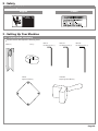
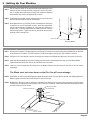
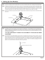
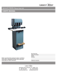
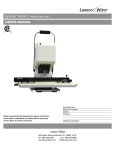
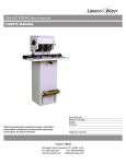
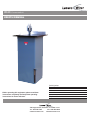
CR-55
Cornerounder
R
USER’S MANUAL
Before operating this equipment, please read these
instructions completely and keep these operating
instructions for future reference.
Serial Number:
Date of Purchase:
Dealer:
Address:
Telephone Number:
485 Hague Street, Rochester, NY 14606 U.S.A.
Tel: 585-436-1934
Fax: 585-464-8665
www.lasscowizer.com
[email protected]
Table Of Contents
1 - Introduction
1.1
1.2
Your New CR-55.................................. Page 01
Shipping Damage Inspection............... Page 01
2 - Safety
2.1
2.2
Safety Instructions................................ Page 01
Warning Labels..................................... Page 02
3 - Setting Up Your Machine
3.1
3.2
3.3
3.4
3.5
Loose Items Inventory.......................... Page 02
Installing the Leveling Feet.................. Page 03
Cutting Blade & Die Installation............ Page 03
Adjusting the Side Guides.................... Page 04
Adjusting the Blade Height................... Page 04
4 - Operation
4.1
4.2
4.3
Corner Rounding Operation................. Page 05
Chip Removal....................................... Page 05
Tips on Cutting..................................... Page 05
5 - Maintenance
5.1
5.2
Safety.................................................... Page 05
Annual Lubrication............................... Page 05
6 - Parts Diagram
6.1
6.2
Parts Diagram....................................... Page 06
Parts List.............................................. Page 06
1 - Introduction
1.1 - Your New CR-55
Thank you for your purchase of the CR-55
Cornerounder .
R
We ask that you take a moment to fill in the serial
number and other information on the front cover of the
manual. Please keep this manual as a reference for
future use.
For parts and service, please contact the Lassco-Wizer
Dealer from whom you purchased the machine. If you
require assistance in locating a Lassco-Wizer Dealer
please contact our customer service department at 585436-1934. Please have the model of your machine and
the serial number when you call.
If you wish to write to us, send correspondence to:
Lassco-Wizer
Attn: Customer Service
485 Hague Street
Rochester, NY 14606
1.2 - Shipping Damage Inspection
Remove the machine from the carton and inspect for
any shipping damage. If any damage is present, report
the damage to the carrier immediately; failure to do so
may void any warranties.
2 - Safety
2.1 - Safety Instructions
All operators must read and understand the Users
Manual including all safety instructions before using this
equipment. Failure to fully understand the safety
instructions can result in personal injury. If after reading the
manual you are still uncertain about use, please
contact the dealer from whom you purchased the
machine for assistance. If you need contact information for
a Service Technician nearest you please call
585-436-1934.
KEEP CHILDREN AWAY. All visitors should be kept a safe
distance from the work area.
SAFETY OF THIS EQUIPMENT IS THE RESPONSIBILITY
OF THE USER(S).
NEVER STAND ON MACHINE. Serious injury could occur
if the machine is tipped.
Please read and follow all warning labels on your machine.
CHECK DAMAGED PARTS. Before further use of the machine, a part that is damaged should be carefully checked
to determine that it will operate properly and perform its intended function--check for alignment of moving parts, binding of moving parts, breakage of parts, mounting, and any
other conditions that may affect its operation. A guard or
other part that is damaged should be properly repaired or
replaced.
Keep hands clear while operating machine.
THIS MACHINE IS DESIGNED FOR ONE PERSON OPERATION. Never operate the machine with more than oneperson.
USE RIGHT MACHINE. Don’t force tool or attachment to
do a job for which it was not designed.
MAINTAIN MACHINE WITH CARE. Keep tools sharp and
clean for best and safest performance. Follow instructions
for maintaining and changing accessories.
Page 01
2 - Safety
2.2 - Warning Labels
English
French
3 - Setting Up Your Machine
3.1 - Loose Items Inventory
Please remove and inspect the following items:
Blade (2)
Die (1)
CR-AG:
Alignment Guide (1)
HEX-18:
Hex Wrench 1/8” (1)
HEX-316:
Hex Wrench 3/16” (1)
HEX-532:
Hex Wrench 5/32” (1)
CR55-PB:
Right Angle Push Block (1)
Page 02
3 - Setting Up Your Machine
3.2 - Installing the Leveling Feet
3.2.1
Set the machine down in its desired location and determine if the
machine is level, making sure that it does NOT rock in any direction. If it does, determine which Leveling Feet need to be adjusted
and whether they need to be adjusted up or down.
3.2.2
If adjustment is needed, start by loosening the four (4) nuts which
are accessed through the rear of the machine.
3.2.3
Next adjust the four (4) Leveling Feet by screwing them clockwise
to raise the or counter-clockwise to lower. After each adjustment
set the machine down completely to verify that the machine no
longer rocks. Continue adjustment as needed until the machine
sits securely in place. Tighten the four (4) nuts down to secure the
position of the Leveling Feet.
Nut
Leveling Feet
Base of the Machine
3.3 - Installing the Blade and Die
3.3.1
Remove the Pressure Foot assembly from the Pressure Foot Mount by unscrewing the threaded knob on the front
of the Pressure Foot Block. Pull the Pressure Foot Block straight out away from the machine to remove.
3.3.2
Using the 5/32” Hex Wrench, remove the two(2) hex screws for the Blade and the one(1) hex screw for the Die.
3.3.3
Insert the desired Blade in its position making sure the blade is positioned all the way up in the Blade Holder.
Tighten down the two(2) hex screws for the Blade until it is secure.
3.3.4
Insert the new corresponding Die facing the new Blade. Replace the hex screw for the Die but do not tighten
completely.
The Blade must not come down on the Die, this will cause damage
3.3.5
Press down on the Foot Pedal bringing the Blade all the way down. Position the Die so that it fits tightly against the
Blade. Tighten down the Hex Screw for the Die until it is secure.
3.3.6
Reattach the Pressure Foot by sliding the Pressure Foot Block back into place noting the holes in the Pressure
Foot Block must align with the two(2) pins on the Pressure Foot Mount. Insert the threaded knob and tighten down
until the Pressure Foot is secure.
Pressure Foot Block
Pressure Foot Mount
Threaded Knob
Blade
Pressure Foot
Die
Page 03
3 - Setting Up Your Machine
3.4 - Adjusting the Side Guides
3.4.1
It may be necessary at times to adjust either one or both of the Side Guides due to misalignment with the Blade.
3.4.2
To Adjust the Side Guides, loosen the three 1/4-20 X 3/4” Socket Head Cap Screws located on both Side Guides
with the 3/16 Hex Wrench (HX-316). Using the Alignment Guide (CR-AG) provided and place it on the table making sure to line it up with the side guides so that they are aligned with the Die. It is necessary to use the foot pedal
to bring the Blade down and confirm that the Alignment Guide is aligned with the edges of the blade.
3.4.3
When the Side Guides are positioned as desired, tighten down the Socket Head Cap Screws until the Side Guides
are secure.
Side Guide
Side Guide
Table
Threaded Knob
3.5 - Adjusting the Height of the Blade
3.5.1
The blades for the CR-55 may dull over time and can be sharpened. To accomodate the fact that sharpening the
blades will change the overall length of the blade, there are two(2) set screws to adjust the height of the blade
located in the Pressure Foot Mount. These set screws can be accessed from the two(2) threaded holes in the top
of the Pressure Foot Mount.
IT IS ONLY NECESSARY TO MAKE THIS ADJUSMENT IF THE BLADE HAS BEEN
SHARPENED
3.5.2
Insert the Blade into the Blade Holder and secure but do not tighten the the two(2) hex screws. Insert the 1/8” Hex
Wrench (HX-18) provided into the Threaded Holes in the top of the Pressure Foot Mount, engage the Set Screws,
and turn clockwise to lower the overall height of the Blade. Turn clockwise until the bottom of the Blade sits just
higher than the Pressure Foot. Tighten down the Blade. Test the full motion of the blade by stepping on the foot
pedal, to ensure that the Blade comes down past the top of the Die.
__” Hex Wrench
Threaded Holes (Set Screws inside)
Page 04
4 - Operation
4.1 - Corner Rounding Operation
4.1.1
Place the product you are cutting onto the Metal Top Plate and push it into the corner aligning it with the Two(2) Side
guides.
4.1.2
Press down firmly to prevent the product from sliding out of the corner. We recommend using the Right Angle Push
Block (CR55-PB) provided, if your product allows, to help hold the product in place while cutting.
4.1.3
Press down firmly on the foot pedal until it stops to insure that the blade has travelled all the way down cutting
through the entire stack. Please note that this machine can handle up to a maximum of 2” of product. This amount
will vary depending on what you are cutting. Please test on scrap.
4.1.4
Keeping your foot firmly on the Foot Pedal lift and allow the pedal to return to the upright position. DO NOT remove
your foot from the pedal as this can cause injury.
4.2 - Chip Removal
4.2.1
Place a waste bin or a disposable basket underneath the Chip Chute on the rear of the machine. This will catch the
chips as they are cut and slide down the Chip Chute. Empty as needed.
4.3 - Tips on Cutting
4.3.1
Occasionally, the bottom sheet may not cut. If this occurs, place a piece of card stock underneath the stack you are
cutting. This will give support to the product you are cutting.
4.3.2
When cutting business cards or other small sizes, the bottom card may slide forward. Try either cutting a smaller
stack, place a piece of card stock underneath the stack, or both.
4.3.3
We recommend using the included Right Angle Push Block (CR55-PB) when cutting business cards or other small
size product to help prevent push back.
5 - Maintenance
5.1 - Safety
KEEP HANDS CLEAR WHILE PERFORMING MAINTENANCE ON THIS MACHINE.
MOVING PARTS CAN CRUSH AND CUT.
5.2 - Annual Lubrication
5.2.1
Lightly oil the two(2) Yoke Slide Rods where they enter the adapter ring approximately every two(2) weeks or as
needed depending on use.
Page 05
6 - Parts Diagram
6.1 - Parts Diagram
55-62: Guide Post (1)
55-63: Guide Bushing (1)
55-07: Pressure Foot Block (1)
55-15: Top Yoke (1)
Threaded Hole (Set Screw inside) (2)
55-64: Pressure Foot Mount (1)
FM4-4007: Thumb Screw (1)
55-201A: Pressure Foot Asmb (1)
55-03-L: Paper Guide Left (1)
Blade (1)
55-66: Outer Guard (1)
55-61: Chip Deflector (1)
Die (1)
55-03-R: Paper Guide Right (1)
1/4-20 x 3/4” Socket Head
Cap Screws (6)
55-29: Table (1)
50-18: Pedal (1)
55-09: Pedal Bar (1)
55-02: Stand (1)
Page 06
6 - Parts Diagram
6.1 - Parts Diagram
55-07: Pressure Foot Block (1)
FM4-4007: Thumb Screw (1)
Threaded Hole (Set Screw inside) (2)
55-64: Pressure Foot Mount (1)
55-15: Top Yoke (1)
55-62: Guide Post (1)
55-66: Outer Guard (1)
55-63: Guide Bushing (1)
55-03-L: Paper Guide Left (1)
55-03-R: Paper Guide Right (1)
55-29: Table (1)
55-04: Yoke Slide Rod (2)
1/4-20 x 3/4” Socket Head
Cap Screws(6)
55-16: Bottom Yoke (1)
55-39: Basket (1)
50-18: Pedal (1)
55-09: Pedal Bar (1)
55-08: Draw Rod (1)
50-20: Clevis (1)
55-02: Stand (1)
Page 07