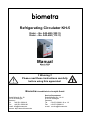
1
biometra Refrigerating Circulator KH-5 Order – No. 043-400 (230 V) Order – No. 043-490 (115 V) Manual March 2008 Manual_KH-5_Ver00 !! Warning !! Please read these instructions carefully before using this apparatus! Biometra biomedizinische Analytik GmbH Rudolf-Wissell-Str. 30 D-37079 Göttingen Germany Tel. +49 551-50686-0 Fax +49 551-50686-66 e-mail: [email protected] internet: http://www.biometra.de Service Department Rudolf-Wissell-Str. 14-16 D-37079 Göttingen Germany Tel. +49 551-50881-10 or -12 Fax +49 551-50881-11 e-mail: [email protected] Table of Contents 1. KEY TO SYMBOLS ..........................................................3 1.1 1.2 SYMBOLS USED IN THIS MANUAL ............................................3 SYMBOLS USED ON THE UNIT .................................................3 2. QUALITY ASSURANCE...................................................5 3. YOUR CONTACTS AT BIOMETRA.................................5 4. TEST CERTIFICATE ........................................................6 5. SAFETY NOTES...............................................................7 6. UNIT DESCRIPTION ......................................................10 6.1 6.2 7. SAFETY FEATURES ..............................................................11 APPLICATIONS ....................................................................12 UNPACKING / SETTING UP..........................................12 7.1 7.2 7.3 7.4 8. TRANSPORTATION DAMAGE? ...............................................12 AMBIENT CONDITIONS ACCORDING TO DIN EN 61010 ..........12 RESTING TIME AFTER TRANSPORTATION ...............................12 VENTILATION.......................................................................12 FUNCTIONAL AND OPERATING ELEMENTS .............13 8.1 9. TEMPERATURE CONTROL MODULE KH-5 ..............................13 CONNECTING HOSES ..................................................14 9.1 9.2 10. PLASTIC HOSES...................................................................15 CONNECTION OF EXTERNAL CLOSED SYSTEMS......................15 FILLING WITH BATH LIQUID 4.....................................16 10.1 10.2 RECOMMENDED BATH LIQUIDS .............................................16 FILLING WITH HEAT TRANSFER LIQUID...................................17 11. DRAINING ......................................................................18 12. CONNECTING UP ..........................................................19 12.1 12.2 12.3 12.4 13. CONNECTING TO THE MAINS .................................................19 CHECKING THE LIQUID CIRCUIT.............................................19 CHANGING THE MAINS PLUG (E.G. FOR GREAT BRITAIN) .......19 FUSES ON THE UNIT .............................................................19 OPERATING...................................................................20 13.1 13.2 13.3 13.4 SWITCHING ON ....................................................................20 HEATING CONTROL LAMP .....................................................20 ADJUSTING THE VARIABLE SET TEMPERATURE......................21 ADJUSTING THE FIXED TEMPERATURES F1 TO F3 (FACULTATIVE)....................................................................21 1 Manual_KH-5_Ver00 Table of Contents 14. EXCESS TEMPERATURE PROTECTION.....................22 14.1 EXCESS TEMPERATURE PROTECTION DIAL ............................22 14.1.1 Setting the excess temperature 14.1.2 Testing the cut–off point 15. CONFIGURATION..........................................................24 15.1 15.2 15.3 15.4 15.5 15.6 15.7 16. SET VALUE S AND FIXED TEMPERATURES F1 TO F3 ..............24 ADJUSTING THE CORRECTION FACTORS (RTA SYSTEM) ........25 DISPLAYING THE VERSION OF THE OPERATING SOFTWARE .....28 SECURED MODE ..................................................................28 ADJUSTING THE LED DISPLAY CONTRAST ............................28 RESOLUTION OF THE TEMPERATURE DISPLAY .......................28 ADJUSTING TEMPERATURE LIMIT VALUES .............................29 FAULT DISPLAYS .........................................................30 16.1 16.2 16.3 16.4 16.5 17. 23 23 EXCESS TEMPERATURE .......................................................30 PUMP OR MOTOR OVERLOADING ..........................................30 SENSOR BREAKAGE OR SHORT CIRCUIT................................31 UNDEFINED FAULT...............................................................31 FAULT ELIMINATED?............................................................31 TESTING THE SAFETY FEATURES.............................32 17.1 EXCESS TEMPERATURE PROTECTION ...................................32 18. COOLING .......................................................................33 19. MAINTENANCE..............................................................34 19.1 19.2 20. CLEANING THE FINS OF THE LIQUEFIER .................................34 DISCARDING THE UNIT: ........................................................34 TECHNICAL SPECIFICATIONS ....................................35 20.1 TECHNICAL SPECIFICATIONS OF THE TEMPERATURE CONTROL MODULE ...............................................................35 21. SERVICE ........................................................................36 22. EQUIPMENT DECONTAMINATION CERTIFICATE .....37 23. NOTE FOR DISPOSAL OF ELECTRIC/ELECTRONIC WASTE ...........................................................................38 23. EC – DECLARATION OF CONFORMITY EU - KONFORMITÄTSERKLÄRUNG ............................39 24. WARRANTY ...................................................................40 2 Manual_KH-5_Ver00 Key to Symbols 1. Key to Symbols 1.1 Symbols used in this manual ! Warns the user of possible damage to the unit, draws attention to the risk of injury or contains safety notes and warnings. Denotes an important remark. 1 ⇒ Indicates the next operating step to be carried out and ... what happens as a result thereof. 1.2 Symbols used on the unit Caution: Read the instruction manual! Adjustment possibility for setting the cut–off point for excess temperature protection Menu selection Value alteration ( ↑ ) higher / ( ↓ ) lower Enter key Reset button (for usage after a fault or interruption) 3 Manual_KH-5_Ver00 * 30.0 Low Limit ∗ 0. 8 1 50 LED display contrast 1. 0 OF Fo n Secured mode 2. 3 1.0 0 Software version 1. 2 Select function and confirm Fixed temperature 3 RTA / Fixed temperature 2 RTA / Fixed temperature 1 RTA / RTA / 70.0 Fixed temperature 3 40.0 Fixed temperature 2 _10.0 Fixed temperature 1 20.0 Set value S Displaying the actual temperature 18.0 1.00 Set value S activated " " in FU = ON , continue pressing only displayed if secured mode is switched on switched on ∗ 70. 0 40. 0 10.0 20. 0 Fixed temperature 1 ∗ Set temperature S Function mode Change or activate set temperature S Displaying the software version ∗ 10 act. set value S or F1 or F2 or F3 ∗ automatic start after unit ON Key to Symbols High Limit = = bright dark Resolution 1.3 Menu Tree 100. 0 ∗ 0.0 10. 1 Quality Assurance/Contacts a Biometra 2. Quality Assurance Biometra implements a Quality Management System certified according to ISO 9001:2000. This guarantees the presence of organizational structures which are necessary to ensure that our products are developed, manufactured and managed according to our customers expectations. Internal and external audits are carried out on a regular basis to ensure that our Quality Management System is fully functional. We also check our products during the manufacturing process to certify that they are produced according to the specifications as well as to monitor correct functioning and to confirm that they are safe. The results are recorded for future reference. Please inform us if, despite our precautionary measures, you should find any product defects. You can thus help us to avoid such faults in future. 3. Your Contacts at Biometra Please get in contact with our Service Department or the authorized distributor who supplied you with the unit if you have any further questions. Biometra GmbH Service Department Rudolf-Wiisell-Straße 14 - 16 D–37079 Goettingen Germany Tel. +49 551-50686-10 or -12 Fax +49 551-50686-11 [email protected] www.biometra.com 5 Manual_KH-5_Ver00 Test Certificate 4. Test Certificate This is to certify that the tempering device which you have acquired and to which these instructions for operation refer has been tested and equilibrated in compliance with the regulations of a certified Quality Assurance System according to DIN ISO 9001. Testing for constancy of temperature has been carried out in keeping with DIN standard DIN 12876 for laboratory equipment. (follow-up standard to DIN standard 58966). The measuring equipment used in the testing process is regularly calibrated and can be traced back to the national norms of the Physikalisch Technische Bundesanstalt (PTB) Deutschlands1 or to other national norms. In those cases where there are no norms and standards on a national level, the testing process is in keeping with currently valid technical rules and regulations, norms and standards. All required measuring data are listed on this page of the Test Certificate. Measuring conditions Ambient temperature: + 20 °C Power supply / -frequency: 230V ± 5V / 50 Hz respectively 115V ± 5V / 60Hz System parameters Volume: 3.5 litre Liquid: Water Rated temperature: +70 °C Measuring process Checking constancy of temperature in bath according to DIN 12876, part 2 (follow-up standard to DIN 58966, part 2, paragraph 4.3) Measuring agent Type of sensor used for measuring: Quartz Inexactitude of measurement according to DIN IEC 751: ± 0.1 K Test results Temperature stability (Width of control range): ± 0.02 K Temperature stability (persistent): ± 0.01 K Accuracy at +70 C: ± 0.1 K 6 Manual_KH-5_Ver00 Safety Notes 5. Safety Notes These notes are intended to draw your attention to risks which only YOU can recognize and avoid or overcome. They are intended to enhance your own safety consciousness. We have set the highest quality standards for ourselves and this unit during development and production. Every unit meets relevant safety regulations. The correct unit usage and proper handling is however solely your responsibility. The intended workplace should correspond to a laboratory or pilot plant environment. The user should have an education level which is at least equivalent to a trained laboratory worker or specialized chemist. The following list should be seen as an example. ! The device may not be operated if there are any doubts regarding a safe operation due to the outer appearance (e.g. damages). ! A safe operation of the instrument cannot be guaranteed if the user does not comply with this instruction manual. ! Ensure that this manual is always at hand for every unit operator. ! Only use this unit solely for the intended application. Repairs, alterations or modifications must only be carried out by specialist personnel. Consider the manufacturer’s instruction manuals. Considerable damage can be caused by improper repairs. The Biometraservice department is at your disposal for repair work. ! Do not operate the unit with wet or oily hands. ! Do not expose the unit to spray water or immerse it in water. ! Do not clean the unit with solvents (fire risk!), a wet cloth soaked in household detergent is normally sufficient. 7 Manual_KH-5_Ver00 Safety Notes ! This device is not designed according to the standard EN 60601–1: 1990 (DIN VDE 0750–1 and IEC 601–1) and should not be operated in rooms used for medical purposes and/or in the vicinity of patients. ! Do not move the unit from the position where it was set up during operation or when it is still hot. There is a high risk of burns! ! Use only recommended bath liquids and read the MSDS of the suppliers. ! The temperature controlling of external vessels or similar objects with the circulator constitutes normal circulator practise. We do not know which substances are contained within these vessels. Many substances are dangerous: • inflammable, easily ignited or explosive • hazardous to health • ! ! environmentally unsafe You alone are responsible for the handling of these substances! Our advice: • If in doubt, consult a safety specialist. • Read the product manufacturer’s or supplier’s EC Safety Data Sheet according to directive 91/155/EEC. • Read relevant regulations concerning dangerous materials. • Observe relevant guidelines for laboratories in your country. The following measures were taken for the protection of the operator: • Protection Class I according to VDE 0106 T1 i.e. protection against electric shocks by grounding all parts which carry the risk of electric contact. The device must only be connected to mains receptacles with a protective ground. 8 Manual_KH-5_Ver00 Safety Notes • Protection IP 20 according to EN 60529 i. e. regarding the protection against accidently touching live parts and damage by foreign matter, it has been ensured that foreign bodies with a thickness or diameter of more than 12 mm cannot penetrate. No special precautions were taken against the penetration of water and dust. The device should therefore not be used in a dusty atmosphere or in the neighborhood of spray water. Do not insert wires or tools in any of the openings. Complete separation from the mains is required when: • • • all dangers caused by this device are to be avoided, cleaning is carried out, repairs or maintenance by specialist personnel is about to be carried out Complete separation means: Pull out the mains plug! 9 Manual_KH-5_Ver00 Unpacking / Setting Up 6. Unit Description This device contains safety elements according to category NFL making it suitable for unattended continuous operation with non–combustible substances as bath liquid (water or water with antifreeze). The circulator pump motor is protected against thermal overloading. Two pump speeds can be selected The safety element measures the surface temperature of the heating element. If this exceeds a certain temperature (due to e.g. a leakage in the liquid circuit or a liquid shortage), the safety element is triggered. The KH-5 circulator offers the possibility of setting this cut–off temperature variably. 10 Manual_KH-5_Ver00 Unpacking / Setting Up 6.1 Safety features The comprehensive safety system is designed on the principle of the concept of the “single fault” (EN 61010). This assumes that two separate faults do not occur simultaneously. This system therefore offers protection against one (single) fault. This one fault will effectively occur automatically if you ... • • do not read this manual, do not correctly set the excess temperature protection, i.e. your safety reserves have already been used up. Such faults can include e.g.: Fault in the temperature control unit: ⇒ Excess temperature ⇒ poss. fire danger Leakage in the liquid circuit or Evaporation of heat transfer liquid: ⇒ Low liquid level ⇒ poss. fire danger, destruction of polyacrylic bath vessel Pump blocked or Great portion of antifreeze in the bath liquid: ⇒ Motor overheating ⇒ poss. fire danger Or also: Excess temperature protection level not correctly set: ⇒ poss. fire danger If a safety feature is triggered • Fault Indentification System (FIS) indicates the fault, • the safety–relevant components of the heating unit (heating element and motor) are switched off immediately i.e. the safety circuit transfers the unit to a stable, safe condition, • the heat transfer liquid in the heating unit gradually adjusts to ambient temperature, but For units with switched on compressor cooling, this cooling remains functional and thus cools the heat transfer liquid to the lowest reachable temperature. 11 Manual_KH-5_Ver00 Unpacking / Setting Up 6.2 Applications Heating and refrigerated circulators: For temperature controlling closed temperature control circuits such reactors, heat exchangers or similar objects. Separate open vessels cannot be temperature controlled as these circulators are only equipped with a pressure pump. 7. Unpacking / Setting Up 7.1 Transportation damage? • • • Notify carrier (forwarding merchant, railroad) etc. Compile a damage report. Before return delivery: Inform dealer or manufacturer (see chapter 21) (Small problems can often be dealt with on the spot). 7.2 Ambient conditions according to DIN EN 61010 • • • • indoors, max. 2000 meters above sea level, ambient temperature 5 ... 40° C, relative humidity max. 80%/31° C (→ 50%/40° C) excess voltage category II, contamination level 2 7.3 Resting time after transportation As we can unfortunately not guarantee that our refrigerated circulators are always transported according to our recommendations (i.e. upright), lubrication oil can leak from the compressor into the cooling circuit. If the refrigerated circulator is started up whilst still in this state, the compressor may be damaged to the lack of oil. Therefore: Rest the unit for 24 hours after setting up. 7.4 Ventilation Keep all ventilation grids 26 free from obstruction to ensure unhindered air circulation. 26 Blocked ventilation grids lead to increased unit heating which in turn reduces the cooling capacity and thus impairs correct functioning. 12 Manual_KH-5_Ver00 Functional and Operating Elements 8. Functional and Operating Elements 8.1 Temperature control module KH-5 front rear 14 27 30 11 15 12 28 16 29 4 8 6 7 2 3 5 A 13 1 A Symbol: Read the instruction manual! 1 2 3 4 5 6 7 8 11 12 13 14 15 16 27 28 29 30 Mains switch Reset button Menu selection key Heating control display Menu position display Set or actual temperature display Value alteration ( ) higher ( ) lower Enter key Mains connection Fuses (if this fuse is triggered, see chap. 12.4) Excess temperature setting dial outlet to application inlet from application fan Switch for cooling on/off Filling level Draining port Display and user interface 13 Manual_KH-5_Ver00 Connecting Hoses 9. Connecting Hoses 4 left Pump nozzle A: left: outlet to external object (pressure side) right: return flow from external object right A out in Hoses are normally used to connect the pump with an external vessel. General recommendations concerning the max. allowable length of hoses cannot be given. It all depends largely on the size, form and material of the external vessel to be temperature controlled. It should be understood that the length of a hose and its diameter combined with the circulating capacity have a large effect on the temperature control effectiveness. Whenever possible, the decision should be made in favor of the wider hose diameter and the vessel to be temperature controlled should be placed as close as possible to the circulator. ! High operating temperatures will lead to high temperatures on the hose surface, this is even more so at the metal nozzles. In this case: DO NOT TOUCH! ! The required hose material is dependent on the heat transfer liquid used. ! Hoses must not be folded or bent! A wide radius should be used if turns have to be made! ! Hoses may become brittle after prolonged use or they may get very soft. They should, therefore, be checked regularly and exchanged if necessary! ! Secure all hose connections using hose clamps! 14 Manual_KH-5_Ver00 Connecting Hoses 9.1 Plastic hoses It must be ensured that the hoses selected are fully suitable for the particular application, i.e. that they will not split, crack or become disengaged from their nozzles. Perbunan hoses have proved to be satisfactory for your circulator. These hoses are available as running meter goods with internal diameters of 8 or 12 mm. Hoses made of other materials are also available from Thermo Scientific. Hoses with 12 mm internal diameter can be pushed directly onto the nozzle A. 9.2 Connection of external closed systems E.g. instruments with a pressure–tight temperature jacket or coil or a heat exchanger. Hose connection: From the pressure port (at the left) to the external object and then back to the return port (at the right). EZ COOL 80 A If it cannot be avoided that the external object is situated higher than the circulator, the heat transfer will only not flow back on the condition that the system is completely tight and leak–free. To be on the safe side it may be considered necessary to fit stop cocks to the inlet and outlet hoses. External Object 15 Manual_KH-5_Ver00 Filling 10. Filling with Bath Liquid 4 10.1 Recommended bath liquids 5 to 80 C Distilled Water • Normal tap water leads to calcareous necessitating frequent unit decalcification. ! Calcium tends to deposit itself on the heating element. The heating capacity is reduced and service life shortened! • Water, of course, can be employed up to 95 C, however above 80 C water vaporization reaches a level which necessitates the liquid to be constantly replenished. deposits Add an appropriate amount of Chloramine T to avoid algae growth in the water. - 10 to 80 C Water with Antifreeze In applications below 5 C the water has to be mixed with an antifreeze. In doing so, the amount of antifreeze added should cover a temperature range 5 C lower (but max. -30 C) than the operating temperature of the particular application. This will prevent the water from gelling (freezing) in the area of the evaporating coil the surface area of which is much colder than the working temperature. An excess of antifreeze deteriorates the temperature accuracy due to its high viscosity. ! Important ! Biometra takes no responsibility for damages caused by the selection of an unsuitable bath liquid. 16 Manual_KH-5_Ver00 Filling 10.2 Filling with heat transfer liquid When working with water or water with antifreeze: Fill the internal tank with about 3.6 liter of heat transfer fluid. Use the filling port at the top left corner of the unit. Adjust carefully to the max level and check the level regularly. If level is below minimum you need to refill. Below the min. level the cooling capacity is decreased significantly. External systems included within the circulating circuit have to be filled with the same heat transfer liquid in order to avoid too much liquid being drawn from the internal bath. The bath level should be checked when the preset temperature has been reached! Quite often closed external systems cannot be prefilled as suggested. In this case the internal bath of the unit has to be filled to the max. level. After starting the unit, the pump will feed the necessary liquid to the external system. Should the demand be higher than the volume difference between high and low, the low liquid level sensor will be activated and the pump switched off. In this case: 2 1 Replenish the liquid, 2 Reset the unit: Depress the key 2 (at the front). ⇒ 3 The unit starts up again Repeat this action if necessary. 17 Manual_KH-5_Ver00 Draining 11. Draining The temp. control unit is drained at the nozzle 23. 23 1 Place a suitable vessel underneath nozzle. Bear in mind that the liquid will run out in a slight arc. 2 Turn plug slowly until it becomes disengaged from the thread. A pin will prevent the liquid from running out right away. 3 Pull out plug (pin) in one quick motion. The liquid will start to run out. 4 Possible residues can be drained by tilting the circulator slightly. ! Hot heat transfer liquid should not be drained! When certain conditions make draining necessary, please act safety conscious: Wear protective clothing and protective gloves! 18 Manual_KH-5_Ver00 Excess Temperature Protection 12. Connecting Up 12.1 Connecting to the mains 230 V 115 V Only attach this unit to mains sockets with a grounded earth. Compare the local mains voltage with the specifications written on the name plate. Voltage deviations of +/– 10% are permissible. The socket must be rated as suitable for the total power consumption of the unit. 12.2 Checking the liquid circuit Before switching on, check again to make sure that the pressure and suction ports are connected with each other - or alternatively if an external object is to be temperature controlled, that the hoses are connected correctly and secured (see chapter 9.2). 12.3 Changing the mains plug (e.g. for Great Britain) ! This should only be carried out by qualified specialist personnel! The mains cable wires have the following colors: Brown = Live Blue = Neutral Green/Yellow = Earth 12.4 Fuses on the unit All units are equipped with automatic thermally–triggered fuses. If the fuse 12 has triggered • the fuse does not have to be exchanged - resetting suffices; • a white marking is visible; • a certain cooling down time should be allowed (approx. 5 min) before the (dip) switch can be pressed again. ! Do not use tools; do not use force. Both destroy the fuse. ! If the fuse should be triggered again after resetting, the unit probably has a defect. In this case the unit should be sent in for servicing. 12 19 Manual_KH-5_Ver00 Excess Temperature Protection 13. Operating 6 4 13.1 Switching on 1 Set the excess temperature protection clearly above the desired operating temperature using the dial 13. 2 Switch the circulator on at the mains switch 1. 5 1 ⇒ 13 27 This causes: Display 6 briefly shows the device thereafter the version number of the software, e.g. ”0.11”, and after temperature at the location of the displayed. identification and operating system that the actual control sensor is ⇒ The display 5 shows which one of the four adjustable set values is currently activated (set temperature ”S” or one of the fixed temperatures ” F1”, ” F2” ,” F2” (see chapter 13.4). ⇒ The pump motor runs - the bath liquid is circulated. The cooling device is switched on via it’s own switch for cooling 27 at the front. The compressor starts with a slight jerk. Only activate cooling device if cooling is actually required. 13.2 Heating control lamp The display 4 lights up when the heating is switched on (set temperature is higher than the actual temperature). ⇒ display 4 lights up constantly during the heating up phase, ⇒ display 4 flashes on and off during the control phase. The display 4 does not light up if the heating is not activated (set temperature is lower than the actual temperature). 20 Manual_KH-5_Ver00 Excess Temperature Protection 13.3 Adjusting the variable set temperature 1 ⇒ 6 7 A left–justified ”S” appears in the small display 5 (for set temperature adjustment). 2 Increase ( ↑ ) or decrease ( ↓ ) the value shown in the display 6 with the buttons 7 . The first degree of temperature change is thereby passed slowly and thereafter the rate of temperature change in the display is five times faster. 3 Press the enter button 8. 8 3 5 Press the menu button 3: ⇒ The selected value is stored as new set temperature and activated. The new value is not saved until the Enter button has been pressed. The circulator continues to use the old set value. The display 6 automatically switches back to actual temperature display after a short time. 13.4 Adjusting the fixed temperatures F1 to F3 (facultative) This device permits permanent storage of three fixed temperatures which can be activated when required. 1 Press the menu button 3 : ⇒ The small display 5 shows F1 (for fixed temperature 1 ), F2 or F3 . 2 Press the buttons 7 to increase ( ↑ ) or decrease ( ↓ ) the value shown in the display 6 . 3 Press the enter button 8 . ⇒ The selected value is stored as fixed temperature F1, F2 or F3 and activated as currently valid set value. The display 6 automatically switches back to actual temperature display after a short time. At the same time the small display 5 shows whether the temperature set point S, F1, F2 or F3 is currently active. To activate another set value, press the menu button 3 until the designator of the desired set point (e.g. ”S” ) is shown in the display 5. Then press the button 8 to confirm without changing the value. 21 Manual_KH-5_Ver00 Excess Temperature Protection 14. Excess Temperature Protection If one of the safety devices is triggered: 6 7 2 • The fault cause is shown in the display 6 (see also chapter 16.). • all voltage conducting unit components (the heating element and pump motor) are switched off immediately i.e. the safety circuit transfers the unit to a stable, safe condition. 13 The fault cause must be identified and remedied. After the fault has been eliminated the unit can be started again by pressing the Reset key 2. 14.1 Excess temperature protection dial It offers protection against dangers caused by an uncontrolled heating up of the heat transfer liquid above the desired set temperature. The cut–off temperature temperature setting dial 13. is adjusted with the excess 13 Proper protection can only be guaranteed if the cut–off point has been correctly set. There are two main aims for correct setting: • Safety (primary importance): Protection against ignition of the heat transfer liquid. The cut–off point must be set at least 25° C below the fire point of the bath liquid used. However, this unit is for use with water only. • Protection of the object to be temperature controlled (secondary importance): Additional protection, e.g. of a biological sample. The cut– off point should be set as close as possible to the desired temperature value. 22 Manual_KH-5_Ver00 Excess Temperature Protection 13 14.1.1 Setting the excess temperature The cut–off point is set with the excess temperature dial 13 with a rough scale of temperature values arranged around it. This scale, of course, can only serve as an approximate setting means for this cut–off point. However, the cut–off point can be determined to act exactly if the following procedure is adhered to: If for instance a bath liquid has a fire point of 60 C the unit should cut off after reaching 35 C at the latest: 1 First set the desired set value “S” using keys 7 (↑) or (↓) to exactly 35° C. 2 After the circulator has reached this temperature, turn the excess temperature dial 13 backwards very slowly (to the left) until the unit cuts off (fault message on display 6). 3 Reset the unit via the Reset key 2 after the heat transfer liquid has cooled down somewhat. 4 Then set the set temperature to the actual temperature (< 35° C). ⇒ The unit can now be used for temperatures below 35° C. As soon as 35° C is reached, it is securely switched off. 14.1.2 Testing the cut–off point Set the set temperature to a higher value than 35° C, set the unit to heat up and watch the digital display or thermometer. The value indicated when the alarm goes off is the real cut–off temperature. The reaching of the cut–off point is indicated at the display by the following message: 23 Manual_KH-5_Ver00 Configuration 6 7 8 3 15. Configuration The device is completely ready for operation after defining the desired set temperature and adjusting the overtemperature protection. It is furthermore possible to adjust or call–up several functions in the function mode ”FU”. 5 FU END Quit configuration mode SOLL Adjust set values S and F1 to F3 RTA Adjust correc– tion factors cS and c1 to c3 CON H-L Version no., temperature resolution, etc. High and low temperature limits 1 Switch to function mode by pressing the menu button 3 several times (until display 5 shows FU). 2 Switch to the desired function SOLL, RTA, CON or H-L with the arrow buttons 7. Press the enter button 8 to confirm the selection made. 3 Move around through the submenus with the menu button 3 (see chapter ”Menu Tree”). 4 A further press of the menu button 3 quits function mode and returns to display of the actual temperature. Display 6 always returns automatically temperature display after a short time. to actual END is provided to skip function mode without making any settings. 15.1 Set value S and fixed temperatures F1 to F3 The adjustment has already been made in chap. 13.3 and 13.4. In the function mode it is also possible to adjust and change these set values without activating them. 1 Press the arrow buttons 7 in the menu FU to change to the SOLL function. Press the enter button 8 to confirm this selection. 2 Press the menu button 3 to move through the submenus S, F1 to F3 (the procedure for making adjustments is the same as in chapter 13.3). A correcting factor c should be associated with each value: S ⇔ cS, F1 ⇔ c1 ... (see chapter 15.2). 24 Manual_KH-5_Ver00 Configuration 15.2 Adjusting the correction factors (RTA system) Display 6 shows the actual temperature at the control sensor. This temperature does not correspond directly to the temperature in the circulator’s bath and even less to the temperature in the external connected system. The temperature difference is determined by measuring the actual current temperature using a suitable measuring device (calibrated or gauged thermometer). This is how the correction factor c (RTA system) is entered into the circulator. It remains stored in the circulator and is automatically assigned to the corresponding set temperature. The same as for the set values in chap. 13.4, four correction factors can be stored: cS , c1 , c2 and c3 , whereby, for example, c1 is the correction value associated with F1. The resolution of the correction factor according to the RTA system is 0.01 °C and the possible range of variation is ±9.9 °C. Entry (see also the example on the next page): 1 Switch to the RTA function with the arrow buttons 7 in the menu FU. Press the enter button 8 to confirm this selection. 2 Press the menu button 3: ⇒ The small display 5 shows cS (correction factor for working with the set temperature S ). 3 Set the determined temperature difference on the display 6 with the buttons 7. 4 Press the enter button 8. ⇒ This confirms the value as new correction factor cS. Proceed analogously as described for cS to adjust the correction factors c1 to c3 for the set values F1 to F3. The new value is not saved until the Enter button has been pressed. The circulator continues to use the old value. Warning: The correction factor ”c” may have to be determined again if the set temperature is altered! 25 Manual_KH-5_Ver00 Configuration The display 6 automatically switches back to actual temperature display after a short time. After the Enter button 8 has been depressed, the correction value “c” (like the set value) remains stored even in case of a power failure. 26 Manual_KH-5_Ver00 Configuration Example: Set value programmed at the circulator Tset = 70.7° C Actual temperature in bath / system Tact = 70.5° C ⇒ Deviation, calculated according to T = Tset - Tact ∆T ⇒∆ Entry of the corrected value ” correction factor “ = 0.2° C T as = +0.2° C The temperature control is thus internally altered so that the desired 70.7 C is also attained in the external system. The temperature displayed at the circulator and that of the external system now correspond with each other. 27 Manual_KH-5_Ver00 Configuration 15.3 Displaying the version of the operating software It is often necessary to know the version number of the software for service and other manufacturer inquiries. 1 Change to con in the menu FU and press button 8 to confirm. Press button 3 to switch to BS . The version number appears in the upper display 6 . 15.4 Secured mode 1 Change to con in the menu FU and press button 8 to confirm. Press button 3 to switch to 88 . 2 Switch security mode ON or OFF with the arrow buttons 7 and press button 8 to confirm. Secured mode: ON The temperature control module switches to the secured mode in case of a power failure or if it is switched on via the mains switch. Display 6 flashes over all segments 8888. Switching on again is only possible after the reset button 2 has been pressed. This is due to safety reasons. The unit reacts in the same way if is switched on via a mains switch in the laboratory. Secured mode: OFF After a power failure or if it is switched on via the mains switch the temperature control module will switch on and start heating corresponding to the stored values and the last temperature used. Please consider any possible resulting risks! ! 15.5 Adjusting the LED display contrast 1 Change to con in the menu FU and press button 8 to confirm. Switch to In with button 3. 2 Press the arrow buttons 7 to change the display contrast (0 to 15) and then press button 8 to confirm the setting. 15.6 Resolution of the temperature display 1 Change to con in the menu FU and press button 8 to confirm. Switch to tA with button 3 . 2 Choose the resolution (0.1 or 0.01° C) with the buttons 7 and then press the button 8 to confirm (0.01° C resolution is available only in the display range from -9.5 to +99.5° C). 28 Manual_KH-5_Ver00 Configuration 15.7 Adjusting temperature limit values The setting range of the operating temperature of the circulator can be limited if the application requires this. This is not a safety element but merely an aid to help avoid user faults when operating the unit. The excess temperature protection must be set separately. ! 1 Change to the function H-L with the arrow buttons 7 in the menu FU. Then press the enter button 8 to confirm the selection. 2 Press the menu button 3 : ⇒ The small display 5 shows LL (Low Limit temperature value). 3 Set the desired limit value with the arrow buttons 7 (the lowest possible temperature is -30° C). 4 Press the enter button 8 . ⇒ The chosen value is stored as low limit value LL . To set the high limit value HL, proceed analogously as described for LL. HL (High Limit): The highest possible temperature is 100° C. The new value is not saved until the Enter key has been pressed. The circulator continues to use the old value. 5 Press the menu button 3 again to quit function mode and return to display of the actual temperature. Or just wait until the displays 5 and 6 automatically return to actual temperature display mode after a short delay. 29 Manual_KH-5_Ver00 Fault Displays 16. Fault Displays 6 2 5 Display 6 shows the fault message ” XXXX ”. ” ” is shown on display 5. The heating element and pump are completely switched off. The following faults are possible: = Excess temperature = Pump or motor overloading = Sensor breakage or short circuit = Undefined fault 16.1 Excess temperature The low liquid level protection can be triggered if: • Excess temperature has been set too closely to the desired working temperature ⇒ increase value slightly according specifications made in chapter 14.1.1. • to the control function is defective ⇒ Return unit for servicing. 16.2 Pump or motor overloading The motor or pump is blocked: ⇒ It can take 10 min or longer, until the motor temperature has sunk far enough so that the unit can be switched on again by pressing the reset key 2. If the circulator switches off again after a short time, return the unit for servicing! 30 Manual_KH-5_Ver00 Fault Displays 16.3 Sensor breakage or short circuit The sensor must be exchanged by qualified service personnel. Please return unit for repairs. 16.4 Undefined fault This can be caused by fault which only occurs for a short period of time, i.e. with a fluctuating bath level when the filling level is very close to minimum. Before returning the unit, top up with heat transfer liquid. This fault can often be remedied in this way! In all other cases this unit must be checked by qualified service personnel. 16.5 Fault eliminated? After the fault has been eliminated, the cause of the fault ). The preceding is shown on the display 6 (e.g. three zeros mean that the fault has been eliminated The reset key 2 must be pressed in order to start up the unit again. 31 Manual_KH-5_Ver00 Testing the Safety Features 17. Testing the Safety Features The safety feature for excess temperature protection must be checked at regular intervals. The level of regularity of checking depends on the unit’s designated application and the heat transfer liquid used (inflammable or non–inflammable). Practical experience has shown that between 6 to 12 times a year is sufficient. 17.1 Excess temperature protection Set a cut–off temperature (see chapter 14.1) that is lower than the desired set temperature. Switch on the circulator and check if the circulator really does switch itself off at the set cut–off temperature If not follow the specifications detailed in chapter 14.1.1. It may be deemed necessary to have the unit checked over by qualified service personnel. 32 Manual_KH-5_Ver00 Cooling 18. Cooling 27 The refrigerated bath is used mainly for enabling lower than ambient or tap water temperatures in circulators or for cooling a heated bath down to a low temperature level very quickly. The working temperature range is shown in the technical specifications. 1 In this case switch the refrigerated bath off at the mains switch 27. Switching the cooling compressor on for quick cooling down purposes (even at working temperatures of 80° C) is however permissible. 33 Manual_KH-5_Ver00 Maintenance 19. Maintenance The stainless steel surfaces of the bath vessel and of the housing may after some time show spots and become tarnished. Normal stainless steel cleaners as they are used in the kitchen can be used. The bath vessel and built–in components should occasionally (at least every time the bath liquid is changed) be cleaned using a household cleaner. Vinegar–based cleaners have proved to be suitable used according to the manufacturers recommendations. Do not use scouring powder! Use only distelled water as temperature fluid to avoid calsium spots. Also to make up water / glycol mixtures. The inside of the bath vessel must be kept clean in order to ensure a long service life. Substances containing acidic or alkaline substances and metal shavings should be removed quickly as they could harm the surfaces causing corrosion. If corrosion (e.g. small rust marks) should occur in spite of this, cleaning with stainless steel caustic agents has proved to be suitable. These substances should be applied according to the manufacturers recommendations. 19.1 Cleaning the fins of the liquefier In order to maintain the cooling capacity of the unit, cleaning has to be done two to four times per year, depending on the grade of soiling. ! Switch off the unit and pull out the mains plug. 19.2 Discarding the unit: One day the life span of your cooling unit will end. Therefore: ! This unit contains ozone–friendly coolant R134a. The unit may however only be discarded authorized personnel. 34 Manual_KH-5_Ver00 by Technical Specifications and Service 20. Technical specifications 20.1 Technical specifications of the temperature control module Operating temperature *) °C -10..80 Temperature accuracy ±K 0.1 Heater capacity 230V / 115V W 1500 / 1100 Pump pressure max. mbar 250 Max. flow rate during circulation using 12 mm ø hoses l/min 12 Voltage V 230 ±10% or 115 ±10% Frequency 230V / 115V Hz 50..60 / 60 Total wattage consumption 230V / 115V VA 2050 / 1250 Safety elements according to category NFL Excess temp. protection variable Motor overload protection yes FIS–system yes Temperature setting digital Setting limitation yes Temperature display LED green RTA–system yes Control type PID Control sensor digital IC * The working temperature range is dependant on the cooling selected. The product is compliant with EN 61000-3-11 requirements and underlies special connection conditions. The maximal electric impedance must not exceed (0.083+ j 0.052) Ohm. 35 Manual_KH-5_Ver00 Technical Specifications and Service 21. Service Should you have any problems with this unit, please contact our service department or your local Biometra dealer: Biometra biomedizinische Analytik GmbH Service Department Rudolf-Wissell-Straße 14 - 16 D-37079 Göttingen Germany Tel. +49 551-50881 – 10 or -12 Fax +49 551-50881 – 11 e-mail: [email protected] Attention: If you would like to send the unit back to us, please read the following instructions. Instructions for return shipment • Return only defective devices. Please contact the Technical Service Department at Biometra (Tel. +49 551-50881 – 10 or -12) to get an Return Authorization Number (RAN number). • Use the original box or a similarly sturdy one. • Label the outside of the box with “CAUTION! SENSITIVE INSTRUMENT!” and the RAN number sticker. Deliveries without RAN number cannot be accepted! • Please enclose a precise description of the fault, which also reveals during which procedures the fault occurred, if possible. Important: Clean all parts of the instrument from residues, and of biologically dangerous, chemical and radioactive contaminants. Please include a written confirmation that the device is free of biologically dangerous and radioactive contaminants in each shipment. If the device is contaminated, it is possible that Biometra will be forced to refuse to accept the device. • The sender of the repair order will be held liable for possible losses resulting from insufficient decontamination of the device. • Please enclose a note which contains the following: a) Sender’s name and address, b) Name of a contact person for further inquiries with telephone number. 36 Manual_KH-5_Ver00 Technical Specifications and Service 22. Equipment Decontamination Certificate To enable us to comply with German law (i.e. §§28 and 80 StrlSchV, §17 GefStoffV and §19 ChemG) and to avoid exposure to hazardous materials during handling or repair, will you please complete this form, prior to the equipment leaving your laboratory COMPANY / INSTITUTE _________________________________________________________ ADDRESS PHONE NO _________________________________________________________ _________________________ FAX NO__________________________ E-MAIL _______________________________________________________________________ EQUIPMENT If on loan / evaluation Model Serial No ______________ ______________ ______________ ______________ ______________ ______________ ______________ ______________ Start Date: __________________ Finish Date __________________ Hazardous materials used with this equipment _______________________________________________________________________________ _______________________________________________________________________________ _______________________________________________________________________________ Method of cleaning / decontamination _______________________________________________________________________________ _______________________________________________________________________________ _______________________________________________________________________________ The equipment has been cleaned and decontaminated: NAME ___________________________________ POSITION _________________________ (HEAD OF DIV./ DEP./ INSTITUTE / COMPANY) SIGNED __________________________________ DATE _____________________________ PLEASE RETURN THIS FORM TO BIOMETRA GMBH OR YOUR LOCAL BIOMETRA DISTRIBUTOR TOGETHER WITH THE EQUIPMENT. PLEASE ATTACH THIS CERTIFICATE OUTSIDE THE PACKAGING. INSTRUMENTS WITHOUT THIS CERTIFICATE ATTACHED WILL BE RETURNED TO SENDER. 37 Manual_KH-5_Ver00 Technical Specifications and Service 23. Note for Disposal of Electric/Electronic Waste This symbol (the crossed-out wheelie bin) means, that this product should be brought to the return systems and/or separate systems available to endusers according to yours country regulations, when this product has reached the end of its lifetime! For details, please contact your local distributor! This symbol applies only to the countries within the EEA*. *EEA = European Economics Area, comprising all EUmembers plus Norway, Iceland and Liechtenstein. 38 Manual_KH-5_Ver00 Technical Specifications and Service 23. EC – Declaration of Conformity EU - Konformitätserklärung March 2008 im Sinne der EG-Richtlinie über elektrische Betriebsmittel zur Verwendung innerhalb bestimmter Spannungsgrenzen 2006/95/EG following the EC directive about electrical equipment for use within certain limits of voltage 2006/95/EC und / and im Sinne der EG-Richtlinie für die elektromagnetische Verträglichkeit 2004/108/EG following the EC directive about the electromagnetic compatibility 2004/108/EC und / and im Sinne der EG-Richtlinie für Druckgeräte 97/23/EG. following the EC directive about pressure equipment 97/23/EC. Hiermit erklären wir, dass folgender Kühlthermostat, Herewith we declare that the following Refrigarating Circulator, Typ / type: Best.-Nr. / Order No. KH-5 043-400 (230 V), 043-490 (115 V) den grundlegenden Anforderungen der corresponds to the basic requirements of EG-Niederspannungsrichtlinie 2006/95/EG und der EC low voltage directive 2006/95/EC EC and the EG-Richtlinie über die elektromagnetische Verträglichkeit 2004/108/EG und der EC directive about the electromagnetic compatibility 2004/108/EC and the EG-Richtlinie für Druckgeräte 97/23/EG entsprechen. EC directive for pressure equipment 97/23/EC. Dr. Juergen Otte Quality Manager 39 Manual_KH-5_Ver00 Technical Specifications and Service 24. Warranty This laboratory instrument is produced with the highest practical standards of materials, workmanship, and design. The design and manufacture of parts have been conceived with one purpose - to produce units which will give satisfactory service. Biometra GmbH guarantees this unit to be free from defects in materials or workmanship under normal use or service for 24 month from date of shipment. If, during this time, this unit proves defective in materials or workmanship, Biometra GmbH will repair or replace it free of charge if returned to us prepaid. This guarantee does not cover damage in transit, damage caused by carelessness, misuse or neglect, or unsatisfactory performance as a result of conditions beyond our control; or consequential losses as a result of failure of our product. Biometra biomedizinische Analytik GmbH Service Department Rudolf-Wissell-Str. 14-16 D-37079 Göttingen Germany Tel. +49 551-50881-10 or -12 Fax. +49 551-50881-11 e-mail: [email protected] Rudolf-Wissell-Str. 30 D-37079 Göttingen Germany Tel. +49 551-50686-0 Fax +49 551-50686-66 e-mail: [email protected] internet: http://www.biometra.de 40 Manual_KH-5_Ver00