1
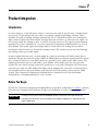
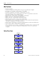
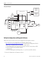
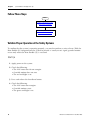
Bidirectional (2-sensor, T-type) Muting
With Enable Using MSR42 Relay
Connected Components Building Block
Catalog Numbers MSR42, MicroLogix 1100, GuardShield Micro 400
Light Curtains
Quick Start
Important User Information
Solid state equipment has operational characteristics differing from those of electromechanical equipment. Safety Guidelines
for the Application, Installation and Maintenance of Solid State Controls (publication SGI-1.1 available from your local Rockwell
Automation sales office or online at http://www.rockwellautomation.com/literature/) describes some important differences
between solid state equipment and hard-wired electromechanical devices. Because of this difference, and also because of the
wide variety of uses for solid state equipment, all persons responsible for applying this equipment must satisfy themselves that
each intended application of this equipment is acceptable.
In no event will Rockwell Automation, Inc. be responsible or liable for indirect or consequential damages resulting from the use
or application of this equipment.
The examples and diagrams in this manual are included solely for illustrative purposes. Because of the many variables and
requirements associated with any particular installation, Rockwell Automation, Inc. cannot assume responsibility or liability for
actual use based on the examples and diagrams.
No patent liability is assumed by Rockwell Automation, Inc. with respect to use of information, circuits, equipment, or software
described in this manual.
Reproduction of the contents of this manual, in whole or in part, without written permission of Rockwell Automation, Inc., is
prohibited.
Throughout this manual, when necessary, we use notes to make you aware of safety considerations.
WARNING
Identifies information about practices or circumstances that can cause an explosion in a hazardous environment,
which may lead to personal injury or death, property damage, or economic loss.
IMPORTANT
Identifies information that is critical for successful application and understanding of the product.
ATTENTION
Identifies information about practices or circumstances that can lead to personal injury or death, property damage,
or economic loss. Attentions help you identify a hazard, avoid a hazard, and recognize the consequence
SHOCK HAZARD
Labels may be on or inside the equipment, for example, a drive or motor, to alert people that dangerous voltage may
be present.
BURN HAZARD
Labels may be on or inside the equipment, for example, a drive or motor, to alert people that surfaces may reach
dangerous temperatures.
Allen-Bradley, Rockwell Automation, TechConnect, MicroLogix, PanelView, Rockwell Software, and GuardShield are trademarks of Rockwell Automation, Inc.
Trademarks not belonging to Rockwell Automation are property of their respective companies.
Where to Start
Connected Components Building Block Outline
Follow the path below to complete your connected components building block.
Connected Components
Building Blocks, publication
CC-QS001
Chapter 1 Product
Integration
ESC
OK
Chapter 2 System
Validation and Application
Tips
3Publication CC-QS016A-EN-P - December 2009
3
Where to Start
4
Publication CC-QS016A-EN-P - December 2009
Table of Contents
Preface
About This Publication . . . . . . . . . . . . . . . . . . . . . . . . . . . . . 7
Conventions . . . . . . . . . . . . . . . . . . . . . . . . . . . . . . . . . . . . . 8
Additional Resources. . . . . . . . . . . . . . . . . . . . . . . . . . . . . . . 8
Chapter 1
Product Integration
Introduction . . . . . . . . . . . . . . . . . . . . . . . . . . . .
Before You Begin . . . . . . . . . . . . . . . . . . . . . . . .
What You Need . . . . . . . . . . . . . . . . . . . . . . . . .
Follow These Steps . . . . . . . . . . . . . . . . . . . . . . .
Understand the Safety Function . . . . . . . . . . . . . .
Set Up the Configuration and Diagnostic Software
Configure the MSR42 Safety Relay . . . . . . . . . . . .
Download the Configuration . . . . . . . . . . . . . . . .
Confirm the Configuration . . . . . . . . . . . . . . . . . .
.
.
.
.
.
.
.
.
.
.
.
.
.
.
.
.
.
.
.
.
.
.
.
.
.
.
.
.
.
.
.
.
.
.
.
.
.
.
.
.
.
.
.
.
.
.
.
.
.
.
.
.
.
.
.
.
.
.
.
.
.
.
.
.
.
.
.
.
.
.
.
.
. 9
. 9
10
10
11
12
13
21
23
Introduction . . . . . . . . . . . . . . . . . . . . . . . . . . . . . .
Before You Begin . . . . . . . . . . . . . . . . . . . . . . . . . .
What You Need . . . . . . . . . . . . . . . . . . . . . . . . . . .
Follow These Steps . . . . . . . . . . . . . . . . . . . . . . . . .
Validate Proper Operation of the Safety Systems. . . .
Validate Proper Operation of the PanelView Screens
.
.
.
.
.
.
.
.
.
.
.
.
.
.
.
.
.
.
.
.
.
.
.
.
.
.
.
.
.
.
.
.
.
.
.
.
25
25
25
26
26
30
Chapter 2
System Validation and
Application Tips
5Publication CC-QS016A-EN-P - December 2009
5
Table of Contents
6
Publication CC-QS016A-EN-P - December 2009
Preface
About This Publication
This quick start illustrates one way of combining a set of Micro 400 Light Curtains, an MSR42
safety relay, an MSR45E expansion module, an MSR127 safety relay, an E-stop, and two
contactors into an integrated safety system providing both a bidirectional, two-sensor, T-type
muting with enable function and an E-stop function.
A MicroLogix™ 1100 controller and a PanelView™ HMI are included to provide a convenient and
graphical way to monitor the operation of the safety systems and provide basic diagnostic
information and corrective action suggestions when appropriate. The MicroLogix controller and
PanelView terminal only monitor the safety systems. They are not safety components and they
have no safety control or function. The safety systems operate independently from the
MicroLogix controller and PanelView terminal.
IMPORTANT
Use this Simple Machine Safety Connected Components Building Block Quick Start in conjunction
with the Connected Components Building Blocks Quick Start, publication CC-QS001.
Refer to Additional Resources on page 8 for a listing of quick starts.
To assist in the design and installation of your system, application files and other information are
provided on the Connected Components Building Blocks Overview CD, publication CC-QR001.
The CD provides bills of materials (BOM), CAD drawings for panel layout and wiring, control
programs, Human Machine Interface (HMI) screens, and more. With these tools and the built-in
best-practices design, the system designer is free to focus on the design of their machine control
and not on design overhead tasks.
Read these sections carefully before beginning work in each chapter. The beginning of each
chapter contains the following information:
• Before You Begin - This section lists the steps that must be completed and decisions that
must be made before starting that chapter.
• What You Need - This section lists the tools that are required to complete the steps in the
current chapter. This includes, but is not limited to, hardware and software.
• Follow These Steps - This illustrates the steps in the current chapter and identifies which
steps are required to complete the examples.
7Publication CC-QS016A-EN-P - December 2009
7
Preface
Conventions
Convention
Meaning
Example
Check or uncheck
To activate or deactivate a checkbox.
Check Disable Keying.
Click
Click the left mouse button once while the cursor is positioned on
object or selection to initiate an action.
Click Browse.
Double-click
Click the left mouse button twice in quick succession while the cursor
is positioned on object or selection to initiate an action.
Double-click the application icon.
Expand
Click the + to the left of a given item /folder to show its contents.
Expand 1768 Bus under I/O Configuration.
Right-click
Click the right mouse button once while the cursor is positioned on
object or selection.
Right-click the 1768 Bus icon.
Select
Using the mouse to highlight a specific option.
Select the New Module folder.
Press
Pressing a specific key on the keyboard or button on a touchscreen.
Press Enter.
>
Use this symbol to indicate the sub-menu name.
Choose File>Menu>Options.
‘Project’
Refers to the application on both the controller side and the PanelView component side.
Additional Resources
8
Resource
Description
Connected Components Building Blocks Quick Start,
publication CC-QS001
Provides information on how to select products and gain access to panel and
wiring information
Connected Components Building Blocks Overview CD,
publication CC-QR001
Provides files for the Connected Components Building Blocks
Position Control Connected Components Building
Block Quick Start, publication CC-QS003
Provides information installing and setting up the PowerFlex 40P drive
parameters with the pre-configured RSLogix 500 program that controls you base
system including application tips, as well as implementing the drive parameter
backup and restore functionality
MicroLogix 1100 Controller User Manual, publication
1763-UM001
Provides information on using the MicroLogix 1100 Programmable Controller
MSR42 Safety Base Module Operating Manual,
publication 440R-IN017
Provides information wiring and operating the MSR42 safety controller
MSR45E Safety Expander Module, Operation Manual,
publication 440R-IN018
Provides information on using the MSR45E expander module
GuardShield Micro 400 Safety Light Curtain Operation
Manual, publication 445L-IN001
Provides information on mounting, wiring, and using safety light curtains
Configuration Tool for MSR42, GuardShield Micro 400
and Safe 2/4 Light Curtains Software Description
Provides information on configuring and programming an MSR42 safety controller
with Configuration Tool software
http://www.ab.com
Provides access to the Allen-Bradley website
http://www.rockwellautomation.com/knowledgebase
Provides access to self-service support
http://www.rockwellautomation.com/components/
connected/blocks.html
Provides access to the Connected Components website
Publication CC-QS016A-EN-P - December 2009
Chapter
1
Product Integration
Introduction
In some instances, especially those where a conveyor runs only at specific time, a bidirectional,
two-sensor, T-type muting with an enable can provide a good safeguarding solution. When
enabled, this type of muting solution automatically lets a valid load or object pass through the
light curtain in either direction without shutting down the machine. A ‘conveyor run’ signal can
be used to enable the muting system, as well as start the conveyor. This signal can be remotely
generated by a host controller, or, as in this Connected Components Building Block, by a local
push button. The enable signal must begin before a load enters the muting system and be
maintained until the load has cleared the muting system. The system lets just one load through
the muting system per enable signal.
A typical application for such a system might be a pick up and drop off (P&D) station for an
automatic storage and retrieval system (ASRS). A forklift places its load for transfer into the system
on a section of conveyor at the P&D station at a guarded access point to the ASRS system. The
forklift operator then presses and holds a push button, which both starts the conveyor and
enables the two-sensor muting system that guards the access point. Muting lets the load on the
conveyor pass into the ASRS without the light curtain stopping the conveyor as the load passes.
The operator releases the push button once the load clears the muting system into the ASRS
system. This Connected Components Building Block is intended to ease the installation,
configuration, and implementation of such a system.
Before You Begin
Review the Connected Components Building Blocks Quick Start, publication CC-QS001, verifying
that you have completed the hardware design and installation as well as software installation.
IMPORTANT
A safety risk assessment must be completed to make sure that all tasks and hazards are
considered and to confirm that the example circuit provides adequate risk reduction for your
specific application.
9Publication CC-QS016A-EN-P - December 2009
9
Chapter 1
Product Integration
What You Need
• Personal computer
• Connected Components Building Blocks Overview CD, publication CC-QR001
• MicroLogix 1100 controller, catalog number 1763-L16BBB
• PanelView Component C600 terminal, catalog number 2711C-T6C
• Stratix 2000 Ethernet switch, catalog number 1783-US05T (or equivalent) to connect the
MicroLogix controller to the PanelView terminal
• Ethernet cables, catalog number 1585J-M8TBJM-2 or equivalent
• MSR127 safety relay, catalog number 440R-N231132
• MSR42 safety relay, catalog number 440R-P226AGS-NNR
• MSR45E expander module, catalog number 440R-P4NANS
• Optical Interface Tool, catalog number 445L-AF6150, which includes the Optical Interface
Tool-MSR42 Configuration and Diagnostic Software
• Optical Interface Tool Fastener, to attach the Optical Interface securely to the MSR42 relay
• 24V DC power supply, catalog number 1606-XL120D
• Safety components such as E-stops, GuardShield Micro 400 light curtains, as listed in the bill
of material on the Connected Components Building Blocks Overview CD, publication
CC-QR001
Follow These Steps
Start
Understand the Safety Function
on page 11
Set Up the Configuration and
Diagnostic Software on page 12
Configure the MSR42 Safety
Relay on page 13
Download the Configuration on
page 21
Confirm the Configuration on
page 23
10
Publication CC-QS016A-EN-P - December 2009
Product Integration
Chapter 1
Understand the Safety Function
This application provides these two separate safety functions:
• The GuardShield Micro 400 light curtains and MSR42 safety relay provide a bidirectional,
two-sensor, T-type muting with an enable function.
• The E-stop and MSR127 safety relay provide an E-stop function.
These two safety functions are independent of one another. When set up properly, either safety
system is capable of stopping dangerous motion.
The MicroLogix 1100 controller monitors the safety systems and, via the PanelView terminal,
provides a simple, graphical representation of the operation and status of the safety systems and
recommends corrective actions in response to system faults. The controller and the terminal
perform no safety or control functions.
If the PanelView terminal is mounted so that it provides the operator a clear and complete view
of the hazard area, and local safety regulations permit, the PanelView START RESET button may
be used to start or reset the safety systems, just like the Start – Reset push button.
IMPORTANT
If the operator stationed at the PanelView terminal’s location cannot see the guarded area well
enough to be certain that no one is in the guarded area, you must not use the START RESET
button.
The START RESET button can be disabled by removing three wires from the MicroLogix controller
I/O.
• Wire 6041
• Wire 10231
• Wire 10071
Publication CC-QS016A-EN-P - December 2009
11
Chapter 1
Product Integration
Safety Systems Diagram
PanelView
Component
Terminal
MicroLogix 1100
800F
Personal
Computer
Stratix
2000
Start
Reset
Enable
RightSight
Sensors
RightSight
Sensors
MSR42
Multifunction
Safety
Relay
GuardShield Micro 400
Light Curtains
MSR45E
Expansion
Controller
MSR127
Safety
Relay
100S-C
100S-C
M
800FP
STOP
Set Up the Configuration and Diagnostic Software
Follow these steps to install and set up the Configuration and Diagnostic software.
1. If you do not have the Configuration and Diagnostic software, go to
http://www.ab.com/safety/logic/relays/msr4x/ to download the Configuration Tool for
MSR42 relay, GuardShield Micro 400 and Safe2/4 Light Curtains.
a. Go to Related Links on the right side of the page and choose ‘Safety Software [ZIP]’.
b. Save the zip file to your personal computer.
c. Unzip the file.
d. Run the SetupDiagnosticAndConfiguration_Vxxx.exe file to install the software.
2. Start the Configuration and Diagnostic software.
12
Publication CC-QS016A-EN-P - December 2009
Product Integration
Chapter 1
3. Click MSR42 and then OK.
4. If this is the first time you have used
the Configuration and Diagnostic
software, register the software.
a. From the Options menu, choose
User Registration.
b. Type in your information and
click OK.
TIP
It is not necessary to change the password for this building block. The default password is
ABGM.
Configure the MSR42 Safety Relay
1. On the Configuration
dialog box, select ‘Micro
400 Light Curtain’ from the
Micro 400 Inputs
pull-down menu.
Publication CC-QS016A-EN-P - December 2009
13
Chapter 1
Product Integration
2. Edit the settings as shown.
a. Choose Manual.
b. Leave Stop Delay set to No.
c. Choose Resolution 30 mm.
d. From the Protective height
pull-down menu, choose 1200
mm.
The software automatically
displays 48 as the ‘Total beam
number of system (n):’.
e. Leave Double Scan set to Yes.
3. Click OK.
Notice that Micro 400 Light
Curtains have been added
to the Design Output
diagram.
14
Publication CC-QS016A-EN-P - December 2009
Product Integration
Chapter 1
4. On the Configuration
dialog box, select Start
from the IN1 Inputs
pull-down menu.
In addition to the
Micro 400 Light Curtains, a
NO momentary push
button, connected to IN1,
appears on the Design
Output diagram. The red
error message disappears,
replaced by ‘Design OK’.
5. From the IN2 pull-down
menu, choose Start
Release.
Notice that Start Release is
shown connected to IN2.
Start Release is a feedback
circuit that confirms, at
Start – Reset, that neither of
the two final switching
devices (FSD)
normally-open (NO)
outputs are shorted, that is,
closed.
In this application, the Start
Release circuit goes from
+24V through one auxiliary
normally-closed (NC)
contact of each 100S
contactor to the MSR42
relay. Similar to EDM, if
either or both of these NC
contacts are open, the
MSR42 relay cannot be
started or reset.
Publication CC-QS016A-EN-P - December 2009
15
Chapter 1
Product Integration
6. From the Outputs Info1
pull-down menu, choose
Micro 400 Light Curtain.
Status Micro 400 Light
Curtain is shown
connected to Info1. This
output switches High or
Low, depending on
whether the light curtain
beam is broken or
complete. This is
independent of the safety
output and can be
considered an auxiliary
output.
7. From the Inputs GPIO
pull-down menu, choose
Muting Micro 400.
8. Click OK on the safety-notice dialog box.
16
Publication CC-QS016A-EN-P - December 2009
Product Integration
Chapter 1
9. On the Muting dialog box, click 2 sensor T-type with enable.
This dialog box helps you configure your muting system properly.
The Muting dialog box shows that a load on the conveyor can travel from the right, passing
into the hazard (machine) area, or from the left, passing out of the hazard area. As long as
the Enable signal (S3) is active, an object passing in the proper sensor-light curtain sequence
within the configured time constraints, may move past the light curtains without initiating a
safe stop. The light curtains are ignored by the safety system until the object has passed
through the muting system. As soon as the object passes the last sensor in the sequence, the
muting ends. The enable button must be released before it can be pressed again to initiate
another muting sequence.
Publication CC-QS016A-EN-P - December 2009
17
Chapter 1
Product Integration
10. Click Help in the lower right corner of the Muting dialog box.
The Muting Help dialog box shows
the proper timing sequence for
two-sensor, T-type muting with an
enable. A muting sequence is
initiated by the S3 (enable) signal.
Once the enable signal is present, a
load can pass in either direction in
the required enable-sensor-light
curtain-sensor-enable sequence.
Muting is ended when a load clears
the last sensor of the sequence.
The Muting Help dialog box also
provides definitions for the t(sens),
t(espe), t(mute), t(mdo), and
t(msdel) times, which you can
configure on the 2 sensor T-type
dialog box. A load that exceeds any
of these configured times as it
moves across the conveyor causes a
muting error, which results in the
light curtain not being muted. A load
entering the light curtain sensing
field during a muting error triggers a
safe stop.
11. Click Close to return to the Muting dialog box.
18
Publication CC-QS016A-EN-P - December 2009
Product Integration
Chapter 1
12. Type the timing values or use the slider to edit the default values.
Time settings are intended to help make sure that only valid objects of the right size, moving
at the right speed, can initiate and maintain a muting sequence.
You may want to add a few seconds to some of your calculations to allow for variations.
Time Setting
Description
t(sens)
Since both S1 and S2 sensors must be broken simultaneously to initiate a muting sequence, these sensors
should be spaced no further apart than the length of the smallest typical load. Calculate how long a load takes
from the time it first reaches S1 until it reaches S2, based on the speed of the conveyor. This is the t(sens) time
for your system.
t(espe)
The t(espe) of your system is the time from the moment a load reaches S2 until it enters the light curtain
sensing field. Once the light curtain is muted, the load must interrupt the light curtain within 3 seconds.
Therefore, sensor 2 must be placed within 3 seconds travel time from the light curtain. t(espe) should be no
longer than 3 seconds except in extraordinary circumstances supported by the risk assessment.
t(mute)
This setting establishes the maximum length of time the light curtain remains muted. Calculate the length of
time it takes the load to travel from the point where it first reaches the S2 until the trailing edge of the load
leaves the light curtain based on the speed of the conveyor. This is the minimum t(mute) for your system,
which is entered in minutes.
t(mdo)
This setting establishes the maximum length of a Mute Dependent Override. Occasionally, a load may stop
within the light curtain sensing field. It may be difficult to move the load past the light curtain sensing field
with a safe stop in effect. Mute Dependent Override is a function that lets a safety stop be paused and muting
to be re-initiated for the duration of the t(mdo) setting, which lets the load move beyond the light curtain
sensing field. As soon as the load moves past the light curtain sensing field, muting ceases. If the hazardous
area is in clear view of the operator and no personnel or objects are in the hazard area, Mute Dependent
Override can be initiated, in this case, by pressing and releasing the Start/Reset button. Calculate the time it
takes the load to travel from the point where it first reaches the S2, until the trailing edge of the load leaves
the light curtain sensing field, based on the speed of the conveyor.
t(msdel)
In some instances, loads may have gaps that the S1 and S2 sensors might sense through as the load passes.
This could lead to a muting error. One method to avoid such errors is to delay the sensors’ response to allow
for seeing through gaps. The t(msdel) configures that delay time. Unless the gap is very long or the load is
moving very slowly, the gap is present for only a short time. In most instances, the default 0.050 is suitable.
Leave this value set at 0.050.
Publication CC-QS016A-EN-P - December 2009
19
Chapter 1
Product Integration
Notice that the Connecting diagram shows a lamp connected to the lamp output, as well as
muting sensors, S1, S2, and S3 (enable), connected to GPIO1, GPIO2, and GPIO3. The
switch connected to IN1 is labeled Start/Mute override. In this application a Muting Lamp is
required for safety purposes to warn personnel in the area when the light curtain is muted.
13. Review the Additional Settings.
a. Make sure that the Muting Lamp monitored box is checked.
Muting lamp monitoring means that should the muting lamp fail, short, or open, the
MSR42 controller will sense it and not initiate or maintain muting. In applications where a
muting lamp is required, generally the muting lamp is required to be monitored.
b. Because you entered a t(mdo) time earlier, leave the Mute dependent override box
checked.
c. Check the Light curtain interruption monitored box.
14. Click OK to complete the
configuration.
15. Choose File>Save and
save the configuration as
‘2sensor T-type with
enable’.
16. Do not exit the MSR42
configuration and
diagnostic software.
20
Publication CC-QS016A-EN-P - December 2009
Product Integration
Chapter 1
Download the Configuration
1. Write down the device number from the label on the side of the MSR42 relay.
2. Apply power to the MSR42 relay.
3. Attach the suction-cup connector to the interface window on the side of the MSR42 relay.
4. In Microsoft Windows,
open the Control Panel.
5. Double-click on System.
6. On the System Properties
dialog box, click
Hardware.
7. Click Device Manager.
8. Expand Ports (COM &
LPT).
9. Plug the USB connector of
the Optical Interface into
an available USB port on
your personal computer.
10. Note the new COM port
that appears in the list.
This is the port assigned to
the Optical Interface, which you will need to select in the Configuration and Diagnostic
software as part of the download procedure.
11. Close the Control Panel.
12. In the Configuration and Diagnostic software, choose
Options>USB/Comport settings.
If USB/Comport settings is not available, check
TIP
Support Mode active and choose
Options>USB/Comport settings.
Publication CC-QS016A-EN-P - December 2009
21
Chapter 1
Product Integration
13. On the OptiLink Communication dialog box,
select Compatibility mode.
14. Choose the Comport assigned by Windows
Device Manager.
15. Click OK.
16. From the File menu, choose PC->MSR42 (Download).
17. When prompted, type the password ‘ABGM’.
18. On the Controller Description dialog box, type
the six-digit Device number and click OK.
19. Cycle power to the MSR42 relay to allow the
download to proceed.
Once the download is complete, the Configuration control document dialog box appears.
22
Publication CC-QS016A-EN-P - December 2009
Product Integration
Chapter 1
Confirm the Configuration
1. On the Configuration control document
dialog box, review the configuration
and check the confirmation box.
2. Click Continue.
3. When prompted to print the document,
click No.
The software saves a copy that can be
printed later from the File menu.
4. On the Attach Safety Configurator Label dialog
box, click OK.
The MSR42 is now fully configured and ready for
operation.
Publication CC-QS016A-EN-P - December 2009
23
Chapter 1
Product Integration
5. Click the Diagnosis tab.
This screen lets you monitor the status of the light curtain when a computer is attached to
the MSR42 relay via the Optical Interface. It has other helpful diagnostic features that are
described in the MSR42 Safety Base Module Operation Manual, publication 440R-IN017, and
the Configuration Tool for MSR42, GS Micro 400, and Safe 2/4 Light Curtains Software
Description document, available on the CD that ships with the Optical Interface tool.
Otherwise, a personal computer is neither required, nor recommended, for normal system
operation.
6. Disconnect the Optical Interface tool.
24
Publication CC-QS016A-EN-P - December 2009
Chapter
2
System Validation and Application Tips
Introduction
In this chapter, you validate the operation of the two safety functions as well as the operation of
the MicroLogix 1100 controller and PanelView Component 600 terminal.
Before You Begin
• Review the Connected Components Building Blocks Quick Start, publication CC-QS001,
verifying that you have completed all of the steps in Chapter 3 of that publication.
• Verify that you have completed all of the steps in Chapter 1 of this document.
• Verify that all components of the system are assembled and wired per the Bill of Materials
Assembly Diagrams and Wiring Diagrams provided for this Connected Components Building
Block, and as required for your application.
• Verify that the MicroLogix controller and the PanelView Component terminal have power
applied to them.
What You Need
• Personal computer
• Connected Components Building Blocks Overview CD, publication CC-QR001
• MicroLogix 1100 controller, catalog number 1763-L16BBB
• PanelView Component C600 terminal, catalog number 2711C-T6C
• Stratix 2000 Ethernet switch, catalog number 1783-US05T (or equivalent) to connect the
MicroLogix controller to the PanelView terminal
• Ethernet cables, catalog number 1585J-M8TBJM-2 or equivalent
25Publication CC-QS016A-EN-P - December 2009
25
Chapter 2
System Validation and Application Tips
Follow These Steps
Start
Validate Proper Operation of the
Safety Systems on page 26
Validate Proper Operation of the
PanelView Screens on page 30
Validate Proper Operation of the Safety Systems
To confirm that the system is operating properly, you need to perform a series of tests. With the
Mute Enable (S3) integrated into the system to provide a ‘conveyor run’ signal, guarded motion
occurs only when the Mute Enable (S3) is activated.
Start Up
1. Apply power to the system.
2. Check the following:
• The 100S contactors do not energize.
• Guarded motion does not start.
• The red stacklight is on.
3. Press and release the Start-Reset button.
4. Check the following:
• The 100S contactors energize.
• Guarded motions starts.
• The green stacklight is on.
26
Publication CC-QS016A-EN-P - December 2009
System Validation and Application Tips
Chapter 2
E-stop Function
1. Activate the Mute Enable (S3) by pressing the push button and leave it active during steps
2…8.
2. Press the E-stop.
3. Check the following:
• The two 100S contactors de-energize.
• Guarded motion stops.
• The red stacklight is on.
4. Press and release the Start-Reset button.
5. Check the following:
• The two 100S contactors remain de-energized.
• Guarded motion does not start.
• The red stacklight remains on.
6. Twist and release the E-stop button.
7. Press and release the Start-Reset button.
8. Check the following:
• The 100S contactors energize.
• Guarded motion starts.
• The green stacklight is on.
Light Curtain Function
1. Activate the Mute Enable (S3) by pressing the push button and leave it active during steps
2…8.
2. Break the light curtain beam and keep it broken, taking care not to block any sensors.
3. Check the following:
• The two 100S contactors de-energize.
• Guarded motion stops.
• The red stacklight is on.
4. While the light curtain beam remains broken, press the Start-Reset button.
Publication CC-QS016A-EN-P - December 2009
27
Chapter 2
System Validation and Application Tips
5. Check the following:
• The two 100S contactors remain de-energized.
• Guarded motion does not start.
• The red stacklight remains on.
6. Restore the light curtain sensing field.
7. Press and release the Start-Reset button.
8. Check the following:
• The 100S contactors energize.
• Guarded motion starts.
• The green stacklight is on.
Muting Function – Mute Dependent Override
1. Activate the Mute Enable (S3) by pressing the push button and leave it active during steps
2…8.
2. Send a load through the muting system.
3. Check the following:
• S1 switches as the load passes and the muting lamp turns on.
• The load passes through the light curtain without the system shutting off.
• S2 switches as the load passes.
• S1 switches as the load leaves
• S2 switches and the muting lamp turns off as the load leaves.
4. Send another load through the muting system.
5. Confirm that S1 switches as the load passes and the muting lamp turns on (or blinks).
6. When the load breaks the light curtain sensing field, check that:
• The two 100S contactors de-energize.
• Guarded motion stops.
• The red stacklight is on.
7. Press and release the Start-Release button to initiate Mute Dependent Override.
28
Publication CC-QS016A-EN-P - December 2009
System Validation and Application Tips
Chapter 2
8. Check the following:
• The muting lamp stays on (not blinking).
• The 100S contactors energize.
• Guarded motion starts.
• The green stacklight is on.
9. As the load clears the light curtain, confirm that the muting lamp starts blinking.
10. Deactivate the Mute Enable (S3).
11. Confirm that the muting lamp turns off.
Muting Error
1. Do not activate the Mute Enable signal (S3).
2. Block the S1 sensor and keep it blocked.
3. Wait the configured t(espe) delay (approximately 3 seconds) for the muting lamp to start
blinking, signalling a muting error.
Lockout
1. Carefully disconnect and reconnect one of the light curtain RJ45 connectors at the MSR42
relay.
2. Make sure the safety output triggers the instant the light curtain is disconnected.
3. Cycle power to the system
This completes the validation of the safety systems.
Publication CC-QS016A-EN-P - December 2009
29
Chapter 2
System Validation and Application Tips
Validate Proper Operation of the PanelView Screens
Most of the buttons are real-time signals from the MSR42 or MSR127 relays, driven via the
MicroLogix 1100 controller to the PanelView terminal. The buttons change in appearance as the
signals driving them change.
This button
Indicates
SEN
1
There is no load in front of the sensor.
SEN
1
A load is in front of the sensor.
LC
The light curtain sensing field is not interrupted.
LC
The light curtain sensing field is interrupted.
E-STOP
The E-stop has been pressed.
The following pages illustrate a typical sequence of PanelView screens. Confirm that the system
and PanelView screens operate as expected by following this sequence.
When you apply power to the system, the Safety System Status screen appears.
30
Publication CC-QS016A-EN-P - December 2009
System Validation and Application Tips
Chapter 2
1. Press MORE INFO for two seconds.
Whenever an action may be
appropriate for an operator to perform,
MORE INFO is displayed on the screen.
Pressing MORE INFO calls the related
message screen.
2. Press RETURN for about five seconds to
return to the previous screen.
3. Press START RESET for 3 seconds and
release.
4. Press and hold the Mute Enable button.
The system should start running. Note that the START RESET button is green only when the
system is ready for a Start Reset. It is no longer green once the system is running.
The Mute Enable signal is active. As the
load passes S1, muting is initiated. The
muting lamp turns on. The load has not
yet interrupted the light curtain sensing
field.
As the load enters the light curtain
sensing field, the LC (light curtain)
button turns red to indicate that the
light curtain has been interrupted. The
Safety Output button remains on.
Publication CC-QS016A-EN-P - December 2009
31
Chapter 2
System Validation and Application Tips
As the load leaves S2, muting ends.
5. Release the Mute Enable button.
6. Press the E-stop.
The screen updates in response.
7. Press MORE INFO.
8. Press RETURN.
9. Twist and release the E-stop.
10. Press START RESET for 3 seconds and
release.
The Safety Output turns on.
The system is ready to run. It will not
run unless Mute Enable is pressed. We
do not need to run the system to validate the rest of the PanelView screens.
32
Publication CC-QS016A-EN-P - December 2009
System Validation and Application Tips
Chapter 2
11. While avoiding the sensors, interrupt
the light curtain and keep it interrupted.
12. Press MORE INFO.
13. Press RETURN.
14. Remove the object interrupting the light
curtain.
Once the light curtain is no longer
interrupted, the display returns to the
Ready for START RESET screen.
15. Press START RESET for 3 seconds and
release.
Publication CC-QS016A-EN-P - December 2009
33
Chapter 2
System Validation and Application Tips
16. Move a dummy load, such as a large empty carton in front of S1.
The muting lamp begins to blink. The
screen reflects a muting error.
17. Press MORE INFO.
18. Press RETURN.
19. With S1 still blocked, move the dummy
load until it interrupts the light curtain
as well.
34
Publication CC-QS016A-EN-P - December 2009
System Validation and Application Tips
Chapter 2
20. Press MORE INFO.
21. Press RETURN.
22. Press START RESET for 3 seconds and
release.
The Safety Output turns on. The load is
still interrupting the light curtain.
Pressing and releasing START RESET
initiated a Mute Dependent Override,
t(mdo). The system switches to muted
operation. Muting ends as soon as the
load clears the light curtain or when the
configured t(mdo) expires.
Publication CC-QS016A-EN-P - December 2009
35
Chapter 2
System Validation and Application Tips
23. Move the dummy load through and out of the system.
TIP
When the START RESET button is green, it may be used in place of the Start Reset push button. If
requirements dictate that remote reset must not be used, do not use it. If the operator stationed at
the PanelView terminal’s location cannot see the guarded area well enough to be certain that no
one is in the guarded area, you must not use the START RESET button.
The START RESET button can be disabled by removing three wires from the MicroLogix controller
I/O.
• Wire 6041
• Wire 10231
• Wire 10071
24. Carefully disconnect then reconnect
one of the light curtain cables from the
MSR42 relay at its RJ45 socket.
25. Press MORE INFO.
26. Press RETURN.
36
Publication CC-QS016A-EN-P - December 2009
System Validation and Application Tips
Chapter 2
27. Press and hold START RESET for 10
seconds.
28. Cycle power to the system. This
completes validation of the PanelView
screens.
Publication CC-QS016A-EN-P - December 2009
37
Chapter 2
38
System Validation and Application Tips
Publication CC-QS016A-EN-P - December 2009
Rockwell Automation Support
Rockwell Automation provides technical information on the Web to assist you in using its products. At
http://www.rockwellautomation.com/support/, you can find technical manuals, a knowledge base of FAQs, technical and
application notes, sample code and links to software service packs, and a MySupport feature that you can customize to make the
best use of these tools.
For an additional level of technical phone support for installation, configuration, and troubleshooting, we offer TechConnect
support programs. For more information, contact your local distributor or Rockwell Automation representative, or visit
http://www.rockwellautomation.com/support/.
Installation Assistance
If you experience an anomoly within the first 24 hours of installation, review the information that's contained in this manual.
You can contact Customer Support for initial help in getting your product up and running.
United States or Canada
1.440.646.3434
Outside United States or
Canada
Use the Worldwide Locator at http://www.rockwellautomation.com/support/americas/phone_en.html,
or contact your local Rockwell Automation representative.
New Product Satisfaction Return
Rockwell Automation tests all of its products to ensure that they are fully operational when shipped from the manufacturing
facility. However, if your product is not functioning and needs to be returned, follow these procedures.
United States
Contact your distributor. You must provide a Customer Support case number (call the phone number
above to obtain one) to your distributor to complete the return process.
Outside United States
Please contact your local Rockwell Automation representative for the return procedure.
Documentation Feedback
Your comments will help us serve your documentation needs better. If you have any suggestions on how to improve this
document, complete this form, publication RA-DU002, available at http://www.rockwellautomation.com/literature/.
Publication CC-QS016A-EN-P - December 2009 40
Copyright © 2009 Rockwell Automation, Inc. All rights reserved. Printed in the U.S.A.