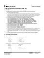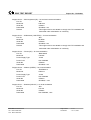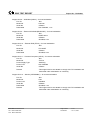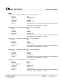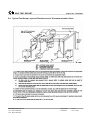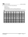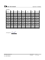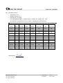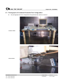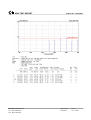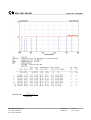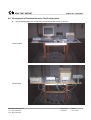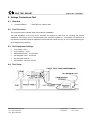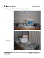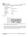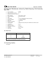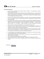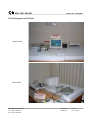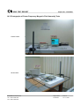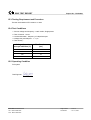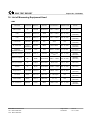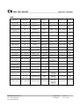
1
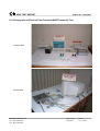
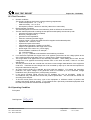
EMC TEST REPORT
Report No. : EC4O0407
CE EMC TEST REPORT
according to
European Standard EN 61000-6-4:2001,
EN 61000-3-2:2000, EN 61000-3-3:1995/A1:2001 and
EN 61000-6-2:2001 ( IEC 61000-4-2:1995/A1:1998,
IEC 61000-4-3:1995/A1:1998, IEC 61000-4-4:1995,
IEC 61000-4-5:1995, IEC 61000-4-6:1996, IEC 61000-4-8:1993,
IEC 61000-4-11:1994 )
Equipment : PANEL PC
Model No. : P108X-845 Series
Applicant
: AXIOMTEK Co., Ltd.
9F, No. 2, Lane 235, Pao Chiao Road, Hsin Tien,
Taipei Hsien, Taiwan, R.O.C.
The test result refers exclusively to the test presented test model / sample.
Without written approval of SPORTON International Inc., the test report shall not be reproduced
except in full.
This test report is only applicable to European Community.
SPORTON International Inc.
6F, No. 106, Sec. 1, Hsin Tai Wu Rd., Hsi Chih, Taipei Hsien, Taiwan, R.O.C.
SPORTON International Inc.
TEL : 886-2-2696-2468
FAX : 886-2-2696-2255
EMC TEST REPORT
Report No. : EC4O0407
Table of Contents
History of this test report...................................................................................................................................iii
CERTIFICATE OF COMPLIANCE........................................................................................................................1
1. General Description of Equipment under Test.............................................................................................2
1.1. Applicant..........................................................................................................................................................................................2
1.2. Manufacturer ...................................................................................................................................................................................2
1.3. Basic Description of Equipment under Test ....................................................................................................................................2
1.4. Feature of Equipment under Test ...................................................................................................................................................2
2. Test Configuration of Equipment under Test ...............................................................................................3
2.1. Test Manner ....................................................................................................................................................................................3
2.2. Description of Test System .............................................................................................................................................................3
3. Test Software ...................................................................................................................................................8
4. General Information of Test............................................................................................................................9
4.1. Test Facility .....................................................................................................................................................................................9
4.2. Test Voltage ....................................................................................................................................................................................9
4.3. Standard for Methods of Measurement...........................................................................................................................................9
4.4. Test in Compliance with ..................................................................................................................................................................9
4.5. Frequency Range Investigated .......................................................................................................................................................9
4.6. Test Distance ..................................................................................................................................................................................9
5. Test of Conducted Powerline .......................................................................................................................10
5.1. Description of Major Test Instruments ..........................................................................................................................................10
5.2. Test Procedures ............................................................................................................................................................................10
5.3. Typical Test Setup Layout of Conducted Powerline .....................................................................................................................11
5.4. Typical Test Setup Layout of Disturbances at Telecommunication Ports .....................................................................................12
5.5. Test Result of AC Powerline Conducted Emission .......................................................................................................................13
5.6. Test Result of disturbances at telecommunication ports...............................................................................................................15
5.7. Photographs of Conducted Powerline Test Configuration ............................................................................................................19
6. Test of Radiated Emission............................................................................................................................20
6.1. Description of Major Test Instruments ..........................................................................................................................................20
6.2. Test Procedures ............................................................................................................................................................................20
6.3. Typical Test Setup Layout of Radiated Emission..........................................................................................................................21
6.4. Test Result of Radiated Emission .................................................................................................................................................22
6.5. Photographs of Radiated Emission Test Configuration ................................................................................................................26
7. Harmonics Test..............................................................................................................................................27
8. Voltage Fluctuations Test.............................................................................................................................28
8.1. Standard........................................................................................................................................................................................28
8.2. Test Procedure..............................................................................................................................................................................28
8.3. Test Equipment Settings ...............................................................................................................................................................28
8.4. Test Setup .....................................................................................................................................................................................28
8.5. Test Result of Voltage Fluctuation and Flicker Test......................................................................................................................29
8.6. Photographs of Harmonics Test, Voltage Fluctuation and Flicker Test ........................................................................................30
9. Electrostatic Discharge Immunity Test (ESD) ............................................................................................31
9.1. Test Setup .....................................................................................................................................................................................31
9.2. Test Setup for Tests Performed in Laboratory ..............................................................................................................................32
9.3. ESD Test Procedure .....................................................................................................................................................................33
9.4. Test Severity Levels ......................................................................................................................................................................34
9.5. Test Points ....................................................................................................................................................................................35
SPORTON International Inc.
TEL : 886-2-2696-2468
FAX : 886-2-2696-2255
Page Number
: i
Issued Date
: Oct. 12, 2004
EMC TEST REPORT
Report No. : EC4O0407
9.6. Photographs of Electrostatic Discharge Immunity Test ................................................................................................................36
10. Radio Frequency Electromagnetic Field Immunity Test (RS).................................................................37
10.1. Test Setup ...................................................................................................................................................................................37
10.2. Test Procedure............................................................................................................................................................................38
10.3. Test Severity Levels ....................................................................................................................................................................38
10.4. Photographs of Radio Frequency Electromagnetic Field Immunity Test ....................................................................................39
11. Electrical Fast Transient/Burst Immunity Test (EFT/BURST) .................................................................40
11.1. Test Setup ...................................................................................................................................................................................40
11.2. Test on Power Line .....................................................................................................................................................................41
11.3. Test on Communication Lines.....................................................................................................................................................41
11.4. Test Procedure............................................................................................................................................................................41
11.5. Test Severity Levels ....................................................................................................................................................................42
11.6. Photographs of Electrical Fast Transient/BURST Immunity Test................................................................................................43
12. Surge Immunity Test ...................................................................................................................................45
12.1. Test Record.................................................................................................................................................................................45
12.2. Test Level....................................................................................................................................................................................45
12.3. Test Procedure............................................................................................................................................................................46
12.4. Operating Condition ....................................................................................................................................................................46
12.5. Photographs of Surge Immunity Test..........................................................................................................................................47
13. Conducted Disturbances Induced by Radio-Frequency Field Immunity Test ( CS )............................48
13.1. Test Level....................................................................................................................................................................................48
13.2. Operating Condition ....................................................................................................................................................................48
13.3. Test Procedure............................................................................................................................................................................49
13.4. Photographs of CS Tests ............................................................................................................................................................50
14. Power Frequency Magnetic Field Immunity Tests ...................................................................................51
14.1. Test Record.................................................................................................................................................................................51
14.2. Test Setup ...................................................................................................................................................................................51
14.3. Photographs of Power Frequency Magnetic Field Immunity Tests .............................................................................................52
15. Voltage Dips and Voltage Interruptions Immunity Tests ........................................................................53
15.1. Test Record of Voltage Interruption ............................................................................................................................................53
15.2. Test Record of Voltage Dips .......................................................................................................................................................53
15.3. Testing Requirement and Procedure ..........................................................................................................................................54
15.4. Test Conditions ...........................................................................................................................................................................54
15.5. Operating Condition ....................................................................................................................................................................54
15.6. Photographs of Voltage Dips and Voltage Interruptions Immunity Tests ....................................................................................55
16. List of Measuring Equipment Used ...........................................................................................................56
17. Notice for Class A Product .........................................................................................................................58
18. Declaration of Conformity and the CE Mark .............................................................................................59
Appendix A. Photographs of EUT........................................................................................................ A1 ~ A41
SPORTON International Inc.
TEL : 886-2-2696-2468
FAX : 886-2-2696-2255
Page Number
: ii
Issued Date
: Oct. 12, 2004
EMC TEST REPORT
Report No. : EC4O0407
History of this test report
Original Report Issue Date: Oct. 12, 2004
▓ No additional attachment.
□ additional attachment were issued as following record :
Attachment No.
SPORTON International Inc.
TEL : 886-2-2696-2468
FAX : 886-2-2696-2255
Issue Date
Description
Page Number
: iii
Issued Date
: Oct. 12, 2004
EMC TEST REPORT
Report No. : EC4O0407
Certificate No. : EC4O0407
CERTIFICATE OF COMPLIANCE
according to
European Standard EN 61000-6-4:2001,
EN 61000-3-2:2000, EN 61000-3-3:1995/A1:2001 and
EN 61000-6-2:2001 ( IEC 61000-4-2:1995/A1:1998,
IEC 61000-4-3:1995/A1:1998, IEC 61000-4-4:1995,
IEC 61000-4-5:1995, IEC 61000-4-6:1996, IEC 61000-4-8:1993,
IEC 61000-4-11:1994 )
Equipment : PANEL PC
Model No. : P108X-845 Series
Applicant
: AXIOMTEK Co., Ltd.
9F, No. 2, Lane 235, Pao Chiao Road, Hsin Tien,
Taipei Hsien, Taiwan, R.O.C.
I HEREBY CERTIFY THAT :
The measurements shown in this test report were made in accordance with the procedures given in
EUROPEAN COUNCIL DIRECTIVE 89/336/EEC. The equipment was passed the test performed according
to European Standard EN 61000-6-4:2001, EN 61000-3-2:2000, EN 61000-3-3:1995/A1:2001 and
EN 61000-6-2:2001 ( IEC 61000-4-2:1995/A1:1998, IEC 61000-4-3:1995/A1:1998, IEC 61000-4-4:1995,
IEC 61000-4-5:1995, IEC 61000-4-6:1996, IEC 61000-4-8:1993, IEC 61000-4-11:1994 ). The test was
carried out on Oct. 11, 2004 at SPORTON International Inc. LAB.
Alex Chen
Manager
SPORTON International Inc.
6F, No. 106, Sec. 1, Hsin Tai Wu Rd., Hsi Chih, Taipei Hsien, Taiwan, R.O.C.
SPORTON International Inc.
TEL : 886-2-2696-2468
FAX : 886-2-2696-2255
Page Number
: 1 of 1
Issued Date
: Oct. 12, 2004
EMC TEST REPORT
Report No. : EC4O0407
1. General Description of Equipment under Test
1.1. Applicant
AXIOMTEK Co., Ltd.
9F, No. 2, Lane 235, Pao Chiao Road, Hsin Tien,
Taipei Hsien, Taiwan, R.O.C.
1.2. Manufacturer
Same as 1.1
1.3. Basic Description of Equipment under Test
Equipment
Model No.
Trade Name
TP Cable
Ext. IDE Cable
Ext. FDD Cable
DIO Cable
PS/2 Y Cable
Audio Cable
Data Cable Type
Power Supply Type
AC Power Cord
: PANEL PC
: P108X-845 Series
: AXIOMTEK
: Non-Shielded, 10 m
: Shielded, 0.4 m
: Shielded, 0.5 m
: Shielded, 0.5 m
: Shielded, 0.3 m
: Shielded, 1 m
: Please see section 2.2 of this test report for details
: Switching
: Non-Shielded, 1.75 m, 3 pin
1.4. Feature of Equipment under Test
CPU: Nation Semiconductor Geode GXl-233/300MHz
HDD: FUJITSU / MHT2020AT / 20GB
LCD Panel:
-AU / B0848N01
-TOSHIBA / LTM08C351
Please refer to user manual for others
SPORTON International Inc.
TEL : 886-2-2696-2468
FAX : 886-2-2696-2255
Page Number
: 2 of 2
Issued Date
: Oct. 12, 2004
EMC TEST REPORT
Report No. : EC4O0407
2. Test Configuration of Equipment under Test
2.1. Test Manner
a. During testing, the interface cables and equipment positions were varied according to
European Standard EN 61000-6-4.
b. The complete test system included remote workstation, SONY Monitor, HP PS/2 Mouse, HP PS/2
Keyboard, LOGITECH USB Mouse, HP Printer, ACEEX Modem, GALAXY Headset, KOKA Walk Man,
BEHAVIOR External CD-ROM, TEAC External FDD and EUT for EMI test. The remote workstation
included ASUS PC, VIEWSONIC Monitor, HP PS/2 Mouse and HP PS/2 Keyboard.
c. The following test modes were pretested for conduction and radiation test:
Mode 1: P1080-845(Panel: AU), LCD+CRT: 800 x 600 38k/60Hz, LAN: 100Mbps
Mode 2: P1080-845(Panel: AU), CRT Only: 1280 x 1024 80k/75Hz, LAN: 100Mbps
Mode 3: P1087-845(Panel: TOSHIBA), LCD+CRT: 800 x 600 38k/60Hz, LAN: 100Mbps
Mode 4: P1087-845(Panel: TOSHIBA), CRT Only: 1280 x 1024 80k/75Hz, LAN: 100Mbps
cause “Mode 4” generated the worst test result, it was reported as final data.
d. The following test modes were performed for Disturbances at Telecommunication Ports test:
Mode 1: P1080-845(Panel: AU), LAN: 100Mbps
Mode 2: P1080-845(Panel: AU), LAN: 10Mbps
Mode 3: P1087-845(Panel: TOSHIBA), LAN: 100Mbps
Mode 4: P1087-845(Panel: TOSHIBA), LAN: 10Mbps
e. The complete test system included remote DELL Notebook, VIEWSONIC Monitor, LOGITECH PS/2
Keyboard, LOGITECH PS/2 Mouse, LOGITECH USB Mouse, CANON Printer, ACEEX Modem,
KOKA Headset, KOKA Walk Man, TEAC External FDD, SONY External CD-ROM and EUT for EMS
test.
f. Frequency range investigated: conduction 150 KHz to 30 MHz, radiation 30 MHz to 1000MHz.
2.2. Description of Test System
< EMI >
Support Unit 1. -- Monitor (SONY) – for local workstation
FCC ID
: AK8GDM17SE2T
Model No.
: GDM-17SE2T
Power Cord
: Shielded
Serial No.
: SP0006
Data Cable
: Shielded, 1.15m
Support Unit 2. -- HP Mouse (LOGITECH) – for local and remote workstation
FCC ID
: JNZ211443
Model No.
: M-S69
Serial No.
: SP0041
Data Cable
: Non-Shielded, 1.85m
SPORTON International Inc.
TEL : 886-2-2696-2468
FAX : 886-2-2696-2255
Page Number
: 3 of 3
Issued Date
: Oct. 12, 2004
EMC TEST REPORT
Report No. : EC4O0407
Support Unit 3. – PS/2 Keyboard (HP) – for local and remote workstation
FCC ID
: N/A
Model No.
: KB-0133
Serial No.
: SP0054
Data Cable
: Shielded, 1.9m
Remark
: This support device was tested to comply with FCC standards and
authorized under a declaration of conformity.
Support Unit 4. – USB Mouse (LOGITECH) – for local workstation
FCC ID
: N/A
Model No.
: M-BE58
Serial No.
: SP0238
Data Cable
: Shielded, 1.8m
Remark
: This support device was tested to comply with FCC standards and
authorized under a declaration of conformity.
Support Unit 5. -- Printer (HP) – for local workstation
FCC ID
: B94C2642X
Model No.
: C2642A
Power Supply Type
: Linear
Power Cord
: Non-Shielded
Serial No.
: SP0048
Data Cable
: Shielded, 1.2m
Support Unit 6. -- Modem (ACEEX) – for local workstation
FCC ID
: IFAXDM1414
Model No.
: DM1414
Power Supply Type
: Linear
Power Cord
: Non-Shielded
Serial No.
: SP0015
Data Cable
: Shielded, 1.15m
Support Unit 7. – Headset (HALAXY) – for local workstation
FCC ID
: N/A
Model No.
: HP-318
Serial No.
: SP0087
Data Cable
: Non-Shielded, 1.8m
SPORTON International Inc.
TEL : 886-2-2696-2468
FAX : 886-2-2696-2255
Page Number
: 4 of 4
Issued Date
: Oct. 12, 2004
EMC TEST REPORT
Report No. : EC4O0407
Support Unit 8. – Walk Man (KOKA) – for local workstation
FCC ID
: N/A
Model No.
: KW-246
Serial No.
: SP0054
Data Cable
: Non-Shielded, 1.7m
Support Unit 9. – External CD-ROM (BEHAVIOR) – for local workstation
FCC ID
: N/A
Model No.
: BCDF 52213
Serial No.
: SP0203
Data Cable
: Shielded, 0.4m
Support Unit 10. – External FDD (TEAC) – for local workstation
FCC ID
: N/A
Model No.
: FD-235HF
Serial No.
: SP0204
Data Cable
: Shielded, 0.5m
Support Unit 11. – Personal Computer (ASUS) – for remote workstation
FCC ID
: N/A
Model No.
: TUSL-2
Power Supply Type
: Switching
Power Cord
: Non-Shielded
Serial No.
: SP0037
Remark
: This support device was tested to comply with FCC standards and
authorized under a declaration of conformity.
Support Unit 12. -- Monitor (VIEWSONIC) – for remote workstation
FCC ID
: N/A
Model No.
: E55
Power Cord
: Shielded
Serial No.
: SP0006
Data Cable
: Shielded, 1.5m
Remark
: This support device was tested to comply with FCC standards and
authorized under a declaration of conformity.
SPORTON International Inc.
TEL : 886-2-2696-2468
FAX : 886-2-2696-2255
Page Number
: 5 of 5
Issued Date
: Oct. 12, 2004
EMC TEST REPORT
Report No. : EC4O0407
< EMS >
Support Unit 1. -- Monitor (VIEWSONIC) – for local workstation
FCC ID
: N/A
Model No.
: VCDTS21553-3J
Power Cord
: Shielded
Serial No.
: SP0006
Data Cable
: Shielded, 1.7m
Remark
: This support device was tested to comply with FCC standards and
authorized under a declaration of conformity.
Support Unit 2. -- PS/2 Keyboard (LOGITECH) – for local workstation
FCC ID
: N/A
Model No.
: Y-SP29
Serial No.
: SP0054
Data Cable
: Shielded, 1.8m
Remark
: This support device was tested to comply with FCC standards and
authorized under a declaration of conformity.
Support Unit 3. – PS/2 Mouse (LOGITECH) – for local workstation
FCC ID
: N/A
Model No.
: M-S34
Serial No.
: SP0001
Data Cable
: Shielded, 1.8m
Remark
: This support device was tested to comply with FCC standards and
authorized under a declaration of conformity.
Support Unit 4. – USB Mouse (LOGITECH) – for local workstation
FCC ID
: N/A
Model No.
: M-BE58
Serial No.
: SP0055
Data Cable
: Shielded, 1.8m
Remark
: This support device was tested to comply with FCC standards and
authorized under a declaration of conformity.
Support Unit 5. -- Printer (CANON) – for local workstation
FCC ID
: N/A
Model No.
: BJ-2100
Power Supply Type
: Linear
Power Cord
: Non-Shielded
Serial No.
: SP0048
Data Cable
: Shielded, 1.35m
Remark
: This support device was tested to comply with FCC standards and
authorized under a declaration of conformity.
SPORTON International Inc.
TEL : 886-2-2696-2468
FAX : 886-2-2696-2255
Page Number
: 6 of 6
Issued Date
: Oct. 12, 2004
EMC TEST REPORT
Report No. : EC4O0407
Support Unit 6. -- Modem (ACEEX) – for local workstation
FCC ID
: IFAXDM1414
Model No.
: DM1414
Power Supply Type
: Linear
Power Cord
: Non-Shielded
Serial No.
: SP0015
Data Cable
: Shielded, 1.15m
Support Unit 7. – Headset (KOKA) – for local workstation
FCC ID
: N/A
Model No.
: HD-305
Serial No.
: SP0095
Data Cable
: Non-Shielded, 1.2m
Support Unit 8. – Walk Man (KOKA) – for local workstation
FCC ID
: N/A
Model No.
: KW-247
Serial No.
: SP0054
Data Cable
: Non-Shielded, 1.7m
Support Unit 9. – External CD-ROM (SONY) – for local workstation
FCC ID
: N/A
Model No.
: CDV5211
Serial No.
: SP0203
Data Cable
: Shielded, 0.4m
Support Unit 10. – External FDD (TEAC) – for local workstation
FCC ID
: N/A
Model No.
: FD-235HF
Serial No.
: SP0204
Data Cable
: Shielded, 0.5m
Support Unit 11. -- Notebook (DELL) – for remote workstation
FCC ID
: N/A
Model No.
: PP01L
Power Supply Type
: Switching
Power Cord
: Non-Shielded
Serial No.
: SP0040
Remark
: This support device was tested to comply with FCC standards and
authorized under a declaration of conformity.
SPORTON International Inc.
TEL : 886-2-2696-2468
FAX : 886-2-2696-2255
Page Number
: 7 of 7
Issued Date
: Oct. 12, 2004
EMC TEST REPORT
Report No. : EC4O0407
3. Test Software
< EMI >
An executive program, EMCTEST.EXE under WIN 98, which generate a complete line of continuously
repeating " H" pattern was used as the test software.
The programs were executed as follows:
a. Turn on the power of all equipment.
b. The PC reads the test program from the hard disk drive and runs it.
c. The PC sends " H" messages to the monitor, and the monitor displays " H" patterns on the screen.
d. The PC sends " H" messages to the printer, then the printer prints them on the paper.
e. The PC sends " H" messages to the modem.
f. The PC sends " H" messages to the internal Hard Disk, and the Hard Disk reads and writes the message.
g. Repeat the steps from b to f.
At the same time, the following programs were executed:
- Executed "CD Player & Media Playe" to play audio.
- Executed "Ping.exe" to link with the remote workstation to receive and transmit data by TP cable.
< EMS >
Two executive programs, EMITEST.EXE & EMCTEST.EXE under WIN 2000, which generate a complete
line of continuously repeating " H" pattern were used as the test software.
The programs were executed as follows:
a. Turn on the power of all equipment.
b. The PC reads the test program from the hard disk drive and runs it.
c. The PC sends " H" messages to the monitor, and the monitor displays " H" patterns on the screen.
d. The PC sends " H" messages to the printer, then the printer prints them on the paper.
e. The PC sends " H" messages to the modem.
f. The PC sends " H" messages to the internal Hard Disk, and the Hard Disk reads and writes the message.
g. Repeat the steps from b to f.
At the same time, the following programs were executed:
- Executed "Network Neighborhood" to link with the remote workstation to receive and transmit data by TP
cable.
- Executed "Media Player" to play audio.
SPORTON International Inc.
TEL : 886-2-2696-2468
FAX : 886-2-2696-2255
Page Number
: 8 of 8
Issued Date
: Oct. 12, 2004
EMC TEST REPORT
Report No. : EC4O0407
4. General Information of Test
4.1. Test Facility
<EMI>
Test Site Location
Test Site No.
<EMS>
Test Site Location
:
No. 3, Lane 238, Kang Lo Street, Nei Hwu District,
Taipei 11424, Taiwan, R.O.C.
TEL : 886-2-2631-4739
FAX : 886-2-2631-9740
: CO01-NH, OS01-NH
: No. 52, Hwa Ya 1St Road, Hwa Ya Technology Park,
Kwei-Shan Hsiang, TaoYuan Hsien, Taiwan, R.O.C.
TEL : 886-3-3273456
FAX : 886-3-3180055
4.2. Test Voltage
230V/50Hz
4.3. Standard for Methods of Measurement
EMI Test
: European Standard EN 61000-6-4
Harmonics Test
: European Standard EN 61000-3-2
Voltage Fluctuations Test
: European Standard EN 61000-3-3
EMS Test
: European Standard EN 61000-6-2
(ESD: IEC 61000-4-2, RS: IEC 61000-4-3, EFT: IEC 61000-4-4, SURGE: IEC 61000-4-5,
CS: IEC 61000-4-6, Power Frequency Magnetic Field: IEC 61000-4-8, DIPS: IEC 61000-4-11)
4.4. Test in Compliance with
EMI Test
: European Standard EN 61000-6-4
Harmonics Test
: European Standard EN 61000-3-2
Voltage Fluctuations Test
: European Standard EN 61000-3-3
EMS Test
: European Standard EN 61000-6-2
(ESD: IEC 61000-4-2, RS: IEC 61000-4-3, EFT: IEC 61000-4-4, SURGE: IEC 61000-4-5,
CS: IEC 61000-4-6, Power Frequency Magnetic Field: IEC 61000-4-8, DIPS: IEC 61000-4-11)
4.5. Frequency Range Investigated
a.
b.
c.
Conducted emission test: from 150 kHz to 30 MHz
Radiated emission test: from 30 MHz to 1,000 MHz
Radio frequency electromagnetic field immunity test: 80-1000 MHz.
4.6. Test Distance
a. The test distance of radiated emission test from antenna to EUT is 10 M.
b. The test distance of radio frequency electromagnetic field immunity test from antenna to EUT is 3 M.
SPORTON International Inc.
TEL : 886-2-2696-2468
FAX : 886-2-2696-2255
Page Number
: 9 of 9
Issued Date
: Oct. 12, 2004
EMC TEST REPORT
Report No. : EC4O0407
5. Test of Conducted Powerline
Conducted Emissions were measured from 150 kHz to 30 MHz with a bandwidth of 9 kHz and return leads of
the EUT according to the methods defined in European Standard EN 61000-6-4. The EUT was placed on a
nonmetallic stand in a shielded room 0.8 meters above the ground plane as shown in section 5.3. The
interface cables and equipment positioning were varied within limits of reasonable applications to determine
the position producing maximum conducted emissions.
5.1. Description of Major Test Instruments
Test Receiver
( R&S ESH3 )
Attenuation
10 dB
Start Frequency
0.15 MHz
Stop Frequency
30 MHz
IF Bandwidth
9 KHz
5.2. Test Procedures
a. The EUT was placed on a desk 0.8 meters height from the metal ground plane and 0.4 meter from the
conducting wall of the shielding room and it was kept at least 0.8 meters from any other grounded
conducting surface.
b. Connect EUT to the power mains through a line impedance stabilization network (LISN).
c.
Connect Telecommunication port to ISN (Impedance Stabilization Network).
d. All the support units are connect to the other LISN.
e. The LISN provides 50 ohm coupling impedance for the measuring instrument.
f.
The CISPR states that a 50 ohm , 50 microhenry LISN should be used.
g. Both sides of AC line were checked for maximum conducted interference.
h. The frequency range from 150 kHz to 30 MHz was searched.
i.
Set the test-receiver system to Peak Detect Function and Specified Bandwidth with Maximum Hold
Mode.
SPORTON International Inc.
TEL : 886-2-2696-2468
FAX : 886-2-2696-2255
Page Number
: 10 of 10
Issued Date
: Oct. 12, 2004
EMC TEST REPORT
Report No. : EC4O0407
5.3. Typical Test Setup Layout of Conducted Powerline
10 cm
80 cm to the ground plane
L.I.S.N.
SPORTON International Inc.
TEL : 886-2-2696-2468
FAX : 886-2-2696-2255
L.I.S.N.
Page Number
: 11 of 11
Issued Date
: Oct. 12, 2004
EMC TEST REPORT
Report No. : EC4O0407
5.4. Typical Test Setup Layout of Disturbances at Telecommunication Ports
SPORTON International Inc.
TEL : 886-2-2696-2468
FAX : 886-2-2696-2255
Page Number
: 12 of 12
Issued Date
: Oct. 12, 2004
EMC TEST REPORT
Report No. : EC4O0407
5.5. Test Result of AC Powerline Conducted Emission
Temperature: 23 °C
Relative Humidity: 42 %
Test Date: Oct. 06, 2004
Corrected Reading (dBuV) = Insertion Loss + Cable Loss + Read Level = Level
All emissions not reported here are more than 10 dB below the prescribed limit.
■ The test was passed at the minimum margin that marked under gray area in the following table
LINE
Frequency Level
Over
(MHz)
(dBµV) Limit (dB)
Limit Line Read Level Insertion Loss Cable Loss Detect Mode
(dBuV)
(dBµV)
(dB)
(dB)
(QP or AV)
0.398
52.26
-26.74
79.00
52.10
0.10
0.06
QP
0.398
51.56
-14.44
66.00
51.40
0.10
0.06
AV
0.455
55.27
-23.73
79.00
55.10
0.10
0.07
QP
0.455
54.27
-11.73
66.00
54.10
0.10
0.07
AV
0.512
50.47
-22.53
73.00
50.30
0.10
0.07
QP
0.512
49.97
-10.03
60.00
49.80
0.10
0.07
AV
0.569
60.08
-12.92
73.00
59.90
0.10
0.08
QP
0.569
59.38
-0.62
60.00
59.20
0.10
0.08
AV
0.626
53.98
-19.02
73.00
53.80
0.10
0.08
QP
0.626
53.28
-6.72
60.00
53.10
0.10
0.08
AV
0.683
52.88
-20.12
73.00
52.70
0.10
0.08
QP
0.683
52.28
-7.72
60.00
52.10
0.10
0.08
AV
SPORTON International Inc.
TEL : 886-2-2696-2468
FAX : 886-2-2696-2255
Page Number
: 13 of 13
Issued Date
: Oct. 12, 2004
EMC TEST REPORT
Report No. : EC4O0407
NEUTRAL
Frequency Level
Over
(MHz)
(dBµV) Limit (dB)
Limit Line Read Level Insertion Loss Cable Loss Detect Mode
(dBuV)
(dBµV)
(dB)
(dB)
(QP or AV)
0.341
49.25
-29.75
79.00
49.10
0.10
0.05
QP
0.341
47.95
-18.05
66.00
47.80
0.10
0.05
AV
0.398
53.36
-25.64
79.00
53.20
0.10
0.06
QP
0.398
52.56
-13.44
66.00
52.40
0.10
0.06
AV
0.455
56.07
-22.93
79.00
55.90
0.10
0.07
QP
0.455
55.37
-10.63
66.00
55.20
0.10
0.07
AV
0.569
60.08
-12.92
73.00
59.90
0.10
0.08
QP
0.569
59.38
-0.62
60.00
59.20
0.10
0.08
AV
0.626
53.38
-19.62
73.00
53.20
0.10
0.08
QP
0.626
52.28
-7.72
60.00
52.10
0.10
0.08
AV
0.683
53.68
-19.32
73.00
53.50
0.10
0.08
QP
0.683
52.58
-7.42
60.00
52.40
0.10
0.08
AV
Test Engineer:
Cash Chu
SPORTON International Inc.
TEL : 886-2-2696-2468
FAX : 886-2-2696-2255
Page Number
: 14 of 14
Issued Date
: Oct. 12, 2004
EMC TEST REPORT
Report No. : EC4O0407
5.6. Test Result of disturbances at telecommunication ports
5.6.1. Test Mode: Mode 1
Temperature: 23 °C
Relative Humidity: 42 %
Test Date: Oct. 06, 2004
Corrected Reading (dBuV) = Insertion Factor + Cable Loss + Read Level = Level
All emissions not reported here are more than 10 dB below the prescribed limit.
■ The test was passed at the minimum margin that marked under gray area in the following table
Frequency Level
Over
(MHz)
(dBvA) Limit (dB)
Limit Line Read Level
(dBvA)
(dBvA)
Insertion
Factor (dB)
Cable Loss Detect Mode
(dB)
(QP or AV)
6.891
45.92
-41.08
87.00
36.10
9.56
0.26
QP
6.891
44.62
-29.38
74.00
34.80
9.56
0.26
AV
11.871
53.79
-33.21
87.00
43.90
9.55
0.34
QP
11.871
51.39
-22.61
74.00
41.50
9.55
0.34
AV
12.456
61.10
-25.90
87.00
51.20
9.55
0.35
QP
12.456
56.30
-17.70
74.00
46.40
9.55
0.35
AV
13.205
58.81
-28.19
87.00
48.90
9.54
0.37
QP
13.205
55.11
-18.89
74.00
45.20
9.54
0.37
AV
24.156
65.69
-21.31
87.00
55.70
9.51
0.48
QP
24.156
63.39
-10.61
74.00
53.40
9.51
0.48
AV
27.156
66.10
-20.90
87.00
56.10
9.50
0.50
QP
27.156
65.40
-8.60
74.00
55.40
9.50
0.50
AV
Test Engineer:
Cash Chu
SPORTON International Inc.
TEL : 886-2-2696-2468
FAX : 886-2-2696-2255
Page Number
: 15 of 15
Issued Date
: Oct. 12, 2004
EMC TEST REPORT
Report No. : EC4O0407
5.6.2. Test Mode: Mode 2
Temperature: 23 °C
Relative Humidity: 42 %
Test Date: Oct. 06, 2004
Corrected Reading (dBuV) = Insertion Factor + Cable Loss + Read Level = Level
All emissions not reported here are more than 10 dB below the prescribed limit.
■ The test was passed at the minimum margin that marked under gray area in the following table
Frequency Level
Over
(MHz)
(dBvA) Limit (dB)
Limit Line Read Level
(dBvA)
(dBvA)
Insertion
Factor (dB)
Cable Loss Detect Mode
(dB)
(QP or AV)
0.556
45.26
-41.74
87.00
35.60
9.59
0.07
QP
0.556
43.06
-30.94
74.00
33.40
9.59
0.07
AV
0.725
46.47
-40.53
87.00
36.80
9.58
0.09
QP
0.725
42.17
-31.83
74.00
32.50
9.58
0.09
AV
0.806
46.57
-40.43
87.00
36.90
9.58
0.09
QP
0.806
44.17
-29.83
74.00
34.50
9.58
0.09
AV
4.389
46.27
-40.73
87.00
36.50
9.56
0.21
QP
4.389
42.47
-31.53
74.00
32.70
9.56
0.21
AV
22.156
36.75
-50.25
87.00
26.80
9.51
0.45
QP
22.156
28.85
-45.15
74.00
18.90
9.51
0.45
AV
23.189
36.37
-50.63
87.00
26.40
9.51
0.47
QP
23.189
29.37
-44.63
74.00
19.40
9.51
0.47
AV
Test Engineer:
Cash Chu
SPORTON International Inc.
TEL : 886-2-2696-2468
FAX : 886-2-2696-2255
Page Number
: 16 of 16
Issued Date
: Oct. 12, 2004
EMC TEST REPORT
Report No. : EC4O0407
5.6.3. Test Mode: Mode 3
Temperature: 23 °C
Relative Humidity: 42 %
Test Date: Oct. 06, 2004
Corrected Reading (dBuV) = Insertion Factor + Cable Loss + Read Level = Level
All emissions not reported here are more than 10 dB below the prescribed limit.
■ The test was passed at the minimum margin that marked under gray area in the following table
Frequency Level
Over
(MHz)
(dBvA) Limit (dB)
Limit Line Read Level
(dBvA)
(dBvA)
Insertion
Factor (dB)
Cable Loss Detect Mode
(dB)
(QP or AV)
7.801
45.43
-41.57
87.00
35.60
9.56
0.27
QP
7.801
44.33
-29.67
74.00
34.50
9.56
0.27
AV
11.837
53.09
-33.91
87.00
43.20
9.55
0.34
QP
11.837
52.49
-21.51
74.00
42.60
9.55
0.34
AV
12.747
62.50
-24.50
87.00
52.60
9.55
0.36
QP
12.747
61.20
-12.80
74.00
51.30
9.55
0.36
AV
13.907
57.52
-29.48
87.00
47.60
9.54
0.38
QP
13.907
56.02
-17.98
74.00
46.10
9.54
0.38
AV
23.128
63.77
-23.23
87.00
53.80
9.51
0.47
QP
23.128
62.07
-11.93
74.00
52.10
9.51
0.47
AV
26.481
65.90
-21.10
87.00
55.90
9.50
0.50
QP
26.481
65.10
-8.90
74.00
55.10
9.50
0.50
AV
Test Engineer:
Cash Chu
SPORTON International Inc.
TEL : 886-2-2696-2468
FAX : 886-2-2696-2255
Page Number
: 17 of 17
Issued Date
: Oct. 12, 2004
EMC TEST REPORT
Report No. : EC4O0407
5.6.4. Test Mode: Mode 4
Temperature: 23 °C
Relative Humidity: 42 %
Test Date: Oct. 06, 2004
Corrected Reading (dBuV) = Insertion Factor + Cable Loss + Read Level = Level
All emissions not reported here are more than 10 dB below the prescribed limit.
■ The test was passed at the minimum margin that marked under gray area in the following table
Frequency Level
Over
(MHz)
(dBvA) Limit (dB)
Limit Line Read Level
(dBvA)
(dBvA)
Insertion
Factor (dB)
Cable Loss Detect Mode
(dB)
(QP or AV)
0.557
43.56
-43.44
87.00
33.90
9.59
0.07
QP
0.557
40.86
-33.14
74.00
31.20
9.59
0.07
AV
0.656
44.16
-42.84
87.00
34.50
9.58
0.08
QP
0.656
41.46
-32.54
74.00
31.80
9.58
0.08
AV
0.728
42.57
-44.43
87.00
32.90
9.58
0.09
QP
0.728
38.57
-35.43
74.00
28.90
9.58
0.09
AV
4.388
40.37
-46.63
87.00
30.60
9.56
0.21
QP
4.388
39.87
-34.13
74.00
30.10
9.56
0.21
AV
22.172
36.45
-50.55
87.00
26.50
9.51
0.45
QP
22.172
28.85
-45.15
74.00
18.90
9.51
0.45
AV
23.199
33.87
-53.13
87.00
23.90
9.51
0.47
QP
23.199
29.67
-44.33
74.00
19.70
9.51
0.47
AV
Test Engineer:
Cash Chu
SPORTON International Inc.
TEL : 886-2-2696-2468
FAX : 886-2-2696-2255
Page Number
: 18 of 18
Issued Date
: Oct. 12, 2004
EMC TEST REPORT
Report No. : EC4O0407
5.7. Photographs of Conducted Powerline Test Configuration
The photographs show the configuration that generates the maximum emission.
FRONT VIEW
REAR VIEW
SPORTON International Inc.
TEL : 886-2-2696-2468
FAX : 886-2-2696-2255
Page Number
: 19 of 19
Issued Date
: Oct. 12, 2004
EMC TEST REPORT
Report No. : EC4O0407
6. Test of Radiated Emission
Radiated emissions from 30 MHz to 1000 MHz were measured with a bandwidth of 120 kHz according to
the methods defines in European Standard EN 61000-6-4. The EUT was placed on a nonmetallic stand, 0.8
meter above the ground plane, as shown in section 6.3. The interface cables and equipment positions were
varied within limits of reasonable applications to determine the positions producing maximum radiated
emissions.
6.1. Description of Major Test Instruments
RF Preamplifier
RF Gain
Signal Input
(HP 8447D)
25 dB
100KHz - 1.3 GHz
Spectrum Analyzer
Attenuation
Start Frequency
Stop Frequency
Resolution Bandwidth
Signal Input
( HP 8568B )
10 dB
30 MHz
1000 MHz
120 KHz
100 Hz to 1.5 GHz
Test Receiver
Resolution Bandwidth
Frequency Band
Quasi-Peak Detector
(HP 85650A )
120 KHz
30 MHz to 1 GHz
ON for Quasi-Peak Mode
OFF for Peak Mode
6.2. Test Procedures
a.
b.
c.
d.
e.
f.
g.
The EUT was placed on a rotatable table top 0.8 meter above ground.
The EUT was set 10 meters from the interference receiving antenna which was mounted on the top of
a variable height antenna tower.
The table was rotated 360 degrees to determine the position of the highest radiation.
The antenna is a half wave dipole and its height is varied between one meter and four meters above
ground to find the maximum value of the field strength both horizontal polarization and vertical
polarization of the antenna are set to make the measurement.
For each suspected emission the EUT was arranged to its worst case and then tune the antenna
tower (from 1 M to 4 M) and turn table (from 0 degree to 360 degrees) to find the maximum reading.
Set the test-receiver system to Peak Detect Function and specified bandwidth with Maximum Hold
Mode.
If the emission level of the EUT in peak mode was 3 dB lower than the limit specified, then testing will
be stopped and peak values of EUT will be reported, otherwise, the emissions which do not have 3 dB
margin will be repeated one by one using the quasi-peak method and reported.
SPORTON International Inc.
TEL : 886-2-2696-2468
FAX : 886-2-2696-2255
Page Number
: 20 of 20
Issued Date
: Oct. 12, 2004
EMC TEST REPORT
Report No. : EC4O0407
6.3. Typical Test Setup Layout of Radiated Emission
Antenna
Equipment under Test
Test distance
0.8 M
Ground Plane
Receiver
TurnTable
SPORTON International Inc.
TEL : 886-2-2696-2468
FAX : 886-2-2696-2255
Page Number
: 21 of 21
Issued Date
: Oct. 12, 2004
EMC TEST REPORT
Report No. : EC4O0407
6.4. Test Result of Radiated Emission
Temperature: 28 °C
Relative Humidity: 56 %
Emission level (dBuV/m) = 20 log Emission level (uV/m)
Corrected Reading: Antenna Factor + Cable Loss + Read Level - Preamp Factor = Level
■ The test was passed at the minimum margin that marked by the frame in the following test record
SPORTON International Inc.
TEL : 886-2-2696-2468
FAX : 886-2-2696-2255
Page Number
: 22 of 22
Issued Date
: Oct. 12, 2004
EMC TEST REPORT
SPORTON International Inc.
TEL : 886-2-2696-2468
FAX : 886-2-2696-2255
Report No. : EC4O0407
Page Number
: 23 of 23
Issued Date
: Oct. 12, 2004
EMC TEST REPORT
SPORTON International Inc.
TEL : 886-2-2696-2468
FAX : 886-2-2696-2255
Report No. : EC4O0407
Page Number
: 24 of 24
Issued Date
: Oct. 12, 2004
EMC TEST REPORT
Report No. : EC4O0407
Test Engineer:
LOUIS LIN
SPORTON International Inc.
TEL : 886-2-2696-2468
FAX : 886-2-2696-2255
Page Number
: 25 of 25
Issued Date
: Oct. 12, 2004
EMC TEST REPORT
Report No. : EC4O0407
6.5. Photographs of Radiated Emission Test Configuration
The photographs show the configuration that generates the maximum emission.
FRONT VIEW
REAR VIEW
SPORTON International Inc.
TEL : 886-2-2696-2468
FAX : 886-2-2696-2255
Page Number
: 26 of 26
Issued Date
: Oct. 12, 2004
EMC TEST REPORT
Report No. : EC4O0407
7. Harmonics Test
As specified on clause 7 and figure Z1 of EN 61000-3-2:2000, the limits are not specified for equipment with
a rated power of 75W or less.
The EUT meets the above condition, so it conforms to EN 61000-3-2.
SPORTON International Inc.
TEL : 886-2-2696-2468
FAX : 886-2-2696-2255
Page Number
: 27 of 27
Issued Date
: Oct. 12, 2004
EMC TEST REPORT
Report No. : EC4O0407
8. Voltage Fluctuations Test
8.1. Standard
Product Standard
: EN 61000-3-3:1995/A1:2001
8.2. Test Procedure
The equipment shall be tested under the conditions of Clause 5.
The total impedance of the test circuit, excluding the appliance under test, but including the internal
impedance of the supply source, shall be equal to the reference impedance. The stability and tolerance of
the reference impedance shall be adequate to ensure that the overall accuracy of ±8% is achieved during the
whole assessment procedure.
8.3. Test Equipment Settings
Line Voltage : 230 V
Line Frequency : 50 Hz
Measurement Delay : 10.0 seconds
Pst Integration Time : 10 minutes
Pst Integration Periods : 1
Test Duration : 00:10:00 minutes
8.4. Test Setup
SPORTON International Inc.
TEL : 886-2-2696-2468
FAX : 886-2-2696-2255
Page Number
: 28 of 28
Issued Date
: Oct. 12, 2004
EMC TEST REPORT
Report No. : EC4O0407
8.5. Test Result of Voltage Fluctuation and Flicker Test
8.5.1. Test Data of Voltage Fluctuation and Flicker
Final Test Result
Temperature
Relative Humidity
Test Date
Urms = 228.9V
Irms = 0.202 A
P
= 19.68 W
Test - Time :
:
:
:
:
PASS
23 ℃
53 % RH
Oct. 08, 2004
Freq = 49.987
Ipk = 0.939 A
Pap = 46.28 VA
1 x 10min = 10min
Range : 2 A
Cf
= 4.647
pf
= 0.425
( 100 %)
LIN (Line Impedance Network) : Soft LIN 0.24 Ohm +j 0.15 Ohm N: 0.16 Ohm +j 0.10 Ohm
Limits :
Plt
: 0.65
dmax : 4.00 %
dtLim : 3.30 %
Pst
:
dc
:
dt>Lim :
1.00
3.30 %
500ms
Test completed, Result: PASSED
Plt =
1
Pst
0.072
0.000
P50s
0.010
P10s
0.010
P3s
0.010
P1s
0.010
P0.1s
0.010
dmax
0.000
dc
0.020
dt>Lim
0.000
Test Engineer:
Kero Kao
SPORTON International Inc.
TEL : 886-2-2696-2468
FAX : 886-2-2696-2255
Page Number
: 29 of 29
Issued Date
: Oct. 12, 2004
EMC TEST REPORT
Report No. : EC4O0407
8.6. Photographs of Harmonics Test, Voltage Fluctuation and Flicker Test
FRONT VIEW
REAR VIEW
SPORTON International Inc.
TEL : 886-2-2696-2468
FAX : 886-2-2696-2255
Page Number
: 30 of 30
Issued Date
: Oct. 12, 2004
EMC TEST REPORT
Report No. : EC4O0407
9. Electrostatic Discharge Immunity Test (ESD)
Final Test Result
:
Pass Performance Criteria :
Required Performance Criteria:
Basic Standard
:
Product Standard
:
Level
:
:
Tested Voltage
:
:
Temperature
:
Relative Humidity
:
Atmospheric Pressure
:
Test Date
:
Observation
:
PASS
A
B
IEC 61000-4-2:1995/A1:1998
EN 61000-6-2:2001
3 for air discharge,
2 for contact discharge
±2 / ±4 / ±8 KV for air discharge,
±2 / ±4 KV for contact discharge
23 °C
54 %
97.8 kPa
Oct. 11, 2004
Normal
9.1. Test Setup
The test setup consists of the test generator, EUT and auxiliary instrumentation necessary to perform
DIRECT and INDIRECT application of discharges to the EUT as applicable, in the follow manner :
a. Contact Discharge to the conductive surfaces and to coupling plane;
b. Air Discharge at insulating surfaces.
The preferred test method is that of type tests performed in laboratories and the only accepted method of
demonstrating conformance with this standard. The EUT was arranged as closely as possible to
arrangement in final installed conditions.
SPORTON International Inc.
TEL : 886-2-2696-2468
FAX : 886-2-2696-2255
Page Number
: 31 of 31
Issued Date
: Oct. 12, 2004
EMC TEST REPORT
Report No. : EC4O0407
9.2. Test Setup for Tests Performed in Laboratory
A ground reference plane was provided on the floor of the test site. It was a metallic sheet (copper or
aluminum) of 0.25 mm, minimum thickness; other metallic may be used but they shall have at least 0.65
mm thickness. In the SPORTON EMC LAB., we provided 1 mm thickness aluminum ground reference
plane or 1 mm thickness stainless steel ground reference plane. The minimum size of the ground reference
plane is 1 m x 1 m, the exact size depending on the dimensions of the EUT. It was connected to the
protective grounding system.
The EUT was arranged and connected according to its functional requirements. A distance of 1m minimum
was provided between the EUT and the wall of the lab. and any other metallic structure. In cases where
this length exceeds the length necessary to apply the discharges to the selected points, the excess length
shall, where possible, be placed non-inductively off the ground reference plane and shall not come closer
than 0.2m to other conductive parts in the test setup.
Where the EUT is installed on a metal table, the table was connected to the reference plane via a cable
with a 470k ohm resister located at each end, to prevent a build-up of charge. The test setup was consist a
wooden table, 0.8m high, standing on the ground reference plane. A HCP, 1.6 m x 0.8 m, was placed on
the table. The EUT and cables was isolated from the HCP by an insulating support 0.5 mm thick. The VCP
size, 0.5 m x 0.5 m.
SPORTON International Inc.
TEL : 886-2-2696-2468
FAX : 886-2-2696-2255
Page Number
: 32 of 32
Issued Date
: Oct. 12, 2004
EMC TEST REPORT
Report No. : EC4O0407
9.3. ESD Test Procedure
a. In the case of air discharge testing the climatic conditions shall be within the following ranges:
- ambient temperature: 15℃ to 35℃;
- relative humidity : 30% to 60%;
- atmospheric pressure : 86 kPa (860 mbar) to 106 kPa (1060 mbar).
b. Test programs and software shall be chosen so as to exercise all normal modes of operation of the EUT.
The use of special exercising software is encouraged, but permitted only where it can be shown that the
EUT is being comprehensively exercised.
c. The test voltage shall be increased from the minimum to the selected test severity level, in order to
determine any threshold of failure. The final severity level should not exceed the product specification
value in order to avoid damage to the equipment.
d. The test shall be performed with both air discharge and contact discharge. On preselected points at
least 10 single discharges (in the most sensitive polarity) shall be applied on air discharge. On
preselected points at least 25 single discharges (in the most sensitive polarity) shall be applied on
contact discharge.
e. For the time interval between successive single discharges an initial value of one second is
recommended. Longer intervals may be necessary to determine whether a system failure has occurred.
f. In the case of contact discharges, the tip of the discharge electrode shall touch the EUT before the
discharge switch is operated.
g. In the case of painted surface covering a conducting substrate, the following procedure shall be
adopted :
- If the coating is not declared to be an insulating coating by the equipment manufacturer, then the
pointed tip of the generator shall penetrate the coating so as to make contact with the conducting
substrate.
- Coating declared as insulating by the manufacturer shall only be submitted to the air discharge.
- The contact discharge test shall not be applied to such surfaces.
h. In the case of air discharges, the round discharge tip of the discharge electrode shall be approached as
fast as possible (without causing mechanical damage) to touch the EUT . After each discharge, the ESD
generator (discharge electrode) shall be removed from the EUT. The generator is then retriggered for a
new single discharge. This procedure shall be repeated until the discharges are completed. In the case
of an air discharge test, the discharge switch, which is used for contact discharge, shall be closed.
SPORTON International Inc.
TEL : 886-2-2696-2468
FAX : 886-2-2696-2255
Page Number
: 33 of 33
Issued Date
: Oct. 12, 2004
EMC TEST REPORT
Report No. : EC4O0407
9.4. Test Severity Levels
9.4.1. Contact Discharge
Level
Test Voltage (KV) of Contact discharge
1
±2
2
±4
3
±6
4
±8
X
Specified
Remark : “X” is an open level.
9.4.2. Air Discharge
Level
Test Voltage (KV) of Air Discharge
1
±2
2
±4
3
±8
4
±15
X
Specified
Remark : “X” is an open level.
SPORTON International Inc.
TEL : 886-2-2696-2468
FAX : 886-2-2696-2255
Page Number
: 34 of 34
Issued Date
: Oct. 12, 2004
EMC TEST REPORT
Report No. : EC4O0407
9.5. Test Points
9.5.1. Test Result of Air Discharge
Test Point
Voltage
Tested No.
LED
±2 / ±4 / ±8 KV
BY 10
Power Switch
±2 / ±4 / ±8 KV
BY 10
VGA Port
±2 / ±4 / ±8 KV
BY 10
Printer Port
±2 / ±4 / ±8 KV
BY 10
PS/2 Port
±2 / ±4 / ±8 KV
BY 10
MIC Jack
±2 / ±4 / ±8 KV
BY 10
Speaker Jack
±2 / ±4 / ±8 KV
BY 10
Line Port
±2 / ±4 / ±8 KV
BY 10
AC Socket
±2 / ±4 / ±8 KV
BY 10
USB Port
±2 / ±4 / ±8 KV
BY 10
Polarity
Voltage
Tested No.
Horizontal (At Front)
±2 / ±4 KV
BY 10
Horizontal (At Left)
±2 / ±4 KV
BY 10
Horizontal (At Right)
±2 / ±4 KV
BY 10
Horizontal (At Rear)
±2 / ±4 KV
BY 10
Vertical (At Front)
±2 / ±4 KV
BY 10
Vertical (At Left)
±2 / ±4 KV
BY 10
Vertical (At Right)
±2 / ±4 KV
BY 10
Vertical (At Rear)
±2 / ±4 KV
BY 10
Case
±2 / ±4 KV
BY 10
Screw
±2 / ±4 KV
BY 10
Bracket
±2 / ±4 KV
BY 10
Com Port
±2 / ±4 KV
BY 10
RJ45 Port
±2 / ±4 KV
BY 10
9.5.2. Test Result of Contact Discharge
Test Engineer:
Kero Kao
SPORTON International Inc.
TEL : 886-2-2696-2468
FAX : 886-2-2696-2255
Page Number
: 35 of 35
Issued Date
: Oct. 12, 2004
EMC TEST REPORT
Report No. : EC4O0407
9.6. Photographs of Electrostatic Discharge Immunity Test
FRONT VIEW
REAR VIEW
SPORTON International Inc.
TEL : 886-2-2696-2468
FAX : 886-2-2696-2255
Page Number
: 36 of 36
Issued Date
: Oct. 12, 2004
EMC TEST REPORT
Report No. : EC4O0407
10. Radio Frequency Electromagnetic Field Immunity Test (RS)
Final Test Result
:
Pass Performance Criteria :
Required Performance Criteria:
Basic Standard
:
Product Standard
:
Level
:
Frequency Range
:
Field Strength
:
Temperature
:
Relative Humidity
:
Atmospheric Pressure
:
Test Date
:
Observation
:
PASS
A
A
IEC 61000-4-3:1995/A1:1998
EN 61000-6-2:2001
3
80-1000 MHz
10 V/m (Modulated 80% AM)
25 °C
54 %
97.8 kPa
Oct. 11, 2004
Normal
10.1. Test Setup
NOTE : The SPORTON 7m x 4m x 4m semichoic chamber is compliance with the sixteen points
uniform field requirement as stated in IEC 1000-4-3 Section 6.2.
The procedure defined in this part requires the generation of electromagnetic fields within which the test
sample is placed and its operation observed. To generate fields that are useful for simulation of actual (field)
conditions may require significant antenna drive power and the resultant high field strength levels. To
comply with local regulations and to prevent biological hazards to the testing personnel, it is recommended
that these tests be carried out in a shielded enclosure or semichoic chamber.
SPORTON International Inc.
TEL : 886-2-2696-2468
FAX : 886-2-2696-2255
Page Number
: 37 of 37
Issued Date
: Oct. 12, 2004
EMC TEST REPORT
Report No. : EC4O0407
10.2. Test Procedure
a. The equipment to be tested is placed in the center of the enclosure on a wooden table. The equipment
is then connected to power and signal leads according to pertinent installation instructions.
b. The antenna which is enabling the complete frequency range of 80-1000 MHz is placed 3m away from
the equipment. The required field strength is determined by placing the field strength meter(s) on top of
or directly alongside the equipment under test and monitoring the field strength meter via a remote field
strength indicator outside the enclosure while adjusting the continuous-wave to the applicable antennae.
c. The test is normally performed with the antenna facing the most sensitive side of the EUT. The
polarization of the field generated by the biconical antenna necessitates testing each position twice,
once with the antenna positioned vertically and again with the antenna positioned horizontally. The
circular polarization of the field from the log-spiral antenna makes a change of position of the antenna
unnecessary.
d. At each of the above conditions, the frequency range is swept 80-1000 MHz, pausing to adjust the R.F.
signal level or to switch oscillators and antenna. The rate of sweep is in the order of 1.5*10-3 decades/s.
The sensitive frequencies or frequencies of dominant interest may be discretely analyzed.
10.3. Test Severity Levels
Frequency Band : 80-1000 MHz
Level
Test field strength (V/m)
1
1
2
3
3
10
X
Specified
Remark : “X” is an open class.
Test Engineer:
Kero Kao
SPORTON International Inc.
TEL : 886-2-2696-2468
FAX : 886-2-2696-2255
Page Number
: 38 of 38
Issued Date
: Oct. 12, 2004
EMC TEST REPORT
Report No. : EC4O0407
10.4. Photographs of Radio Frequency Electromagnetic Field Immunity Test
FRONT VIEW
REAR VIEW
SPORTON International Inc.
TEL : 886-2-2696-2468
FAX : 886-2-2696-2255
Page Number
: 39 of 39
Issued Date
: Oct. 12, 2004
EMC TEST REPORT
Report No. : EC4O0407
11. Electrical Fast Transient/Burst Immunity Test (EFT/BURST)
Final Test Result
:
Pass Performance Criteria :
Required Performance Criteria:
Basic Standard
:
Product Standard
:
Level
:
:
Test Voltage
:
:
Temperature
:
Relative Humidity
:
Atmospheric Pressure
:
Test Date
:
Observation
:
PASS
A
B
IEC 61000-4-4:1995
EN 61000-6-2:2001
on Power Supply -- 3
on I/O signal, data and control line -- 3
on Power Supply -- ±0.5 / ±1.0 / ±2.0 KV
on I/O signal, data and control line -- ±0.25 / ±0.5 / ±1.0 KV
23°C
53%
97.8 kPa
Oct. 11, 2004
Normal
11.1. Test Setup
The EUT was placed on a ground reference plane and was insulated from it by an insulating support about
0.1m thick. If the EUT is table-top equipment, it was located approximately 0.8m above the GRP.. The GRP.
Was a metallic sheet (copper or aluminum) of 0.25 mm ,minimum thickness; other metallic may be used but
they shall have at least 0.65 mm thickness. It shall project beyond the EUT by at least 0.1m on all sides and
connected to the protective earth. In the SPORTON EMC LAB. We provided 1 mm thickness aluminum
ground reference plane or 1 mm thickness stainless steel ground reference plane. The minimum size of the
ground reference plane is 1 m x 1 m, the exact size depending on the dimensions of the EUT. It was
connected to the protective grounding system. The EUT was arranged and connected according to its
functional requirements. The minimum distance between the EUT and other conductive structures, except the
GRP. Beneath the EUT, was more than 0.5 m. Using the coupling clamp, the minimum distance between the
coupling plates and all other conductive structures, except the GRP. Beneath the EUT, was more than 0.5 m.
The length of the signal and power lines between the coupling device and the EUT was 1m or less.
SPORTON International Inc.
TEL : 886-2-2696-2468
FAX : 886-2-2696-2255
Page Number
: 40 of 40
Issued Date
: Oct. 12, 2004
EMC TEST REPORT
Report No. : EC4O0407
11.2. Test on Power Line
a. The EFT/B-generator was located on the GRP.. The length from the EFT/B-generator to the EUT as not
exceed 1 m.
b. The EFT/B-generator provides the ability to apply the test voltage in a non-symmetrical condition to the
power supply input terminals of the EUT.
11.3. Test on Communication Lines
a. The coupling clamp is composed of a clamp unit for housing the cable (length more than 3 m), and was
placed on the GRP..
b. The coupling clamp provides the ability of coupling the fast transient/bursts to the cable under test.
11.4. Test Procedure
a. In order to minimize the effect of environmental parameters on test results, the climatic conditions when
test is carrying out shall comply with the following requirements:
- ambient temperature: 15℃ to 35℃;
- relative humidity : 45% to 75%;
- atmospheric pressure : 86 kPa (860 mbar) to 106 kPa (1060 mbar).
b. In order to minimize the effect of environmental parameters on test results, the electromagnetic
environment of the laboratory shall not influence the test results.
c. The variety and diversity of equipment and systems to be tested make it difficult to establish general
criteria for the evaluation of the effects of fast transients/bursts on equipment and systems.
d. The test results may be classified on the basic of the operating conditions and the functional
specification of the equipment under test, according to the following performance criteria :
- Normal performance within the specification limits.
- Temporary degradation or loss of function or performance which is self-recoverable.
- Temporary degradation or loss of function or performance which requires operator intervention or
system reset.
- Degradation or loss of function which is not recoverable due to damage of equipment (components).
SPORTON International Inc.
TEL : 886-2-2696-2468
FAX : 886-2-2696-2255
Page Number
: 41 of 41
Issued Date
: Oct. 12, 2004
EMC TEST REPORT
Report No. : EC4O0407
11.5. Test Severity Levels
The following test severity levels are recommended for the fast transient/burst test :
Open circuit output test voltage ± 10%
Level
On Power Supply
On I/O signal, data and control line
1
0.5 KV
0.25 KV
2
1.0 KV
0.50 KV
3
2.0 KV
1.00 KV
4
4.0 KV
2.00 KV
X
Specified
Specified
Remark : “ X ” is an open level. The level is subject to negotiation between the user and the manufacturer
or is specified by the manufacturer.
Test Engineer:
Kero Kao
SPORTON International Inc.
TEL : 886-2-2696-2468
FAX : 886-2-2696-2255
Page Number
: 42 of 42
Issued Date
: Oct. 12, 2004
EMC TEST REPORT
Report No. : EC4O0407
11.6. Photographs of Electrical Fast Transient/BURST Immunity Test
FRONT VIEW
REAR VIEW
SPORTON International Inc.
TEL : 886-2-2696-2468
FAX : 886-2-2696-2255
Page Number
: 43 of 43
Issued Date
: Oct. 12, 2004
EMC TEST REPORT
Report No. : EC4O0407
CLAMP
SPORTON International Inc.
TEL : 886-2-2696-2468
FAX : 886-2-2696-2255
Page Number
: 44 of 44
Issued Date
: Oct. 12, 2004
EMC TEST REPORT
Report No. : EC4O0407
12. Surge Immunity Test
Final Test Result
:
Pass Performance Criteria :
Required Performance Criteria:
Basic Standard
:
Product Standard
:
Surge Wave form (Tr/Th)
:
Level
:
:
Test Voltage
:
:
Temperature
:
Relative Humidity
:
Atmospheric Pressure
:
Test Date
:
Observation
:
Remark
:
PASS
A
B
IEC 61000-4-5:1995
EN 61000-6-2:2001
1, 2/50(8/20)μs
on RJ45 port – N/A
on Input AC Power Port – 3
on RJ45 port – N/A
on Input AC Power Port -- ±1.0 / 2.0 KV
23 °C
53 %
97.8 kPa
Oct. 11, 2004
Normal
The test on RJ45 ports is not required due to the normal functioning
cannot be achieved because of the impact of the CDN on the EUT.
12.1. Test Record
Phase Angle
Voltage ( KV ) Test Location
Polarity
0°
90°
180°
270°
Result
+
A
A
A
A
PASS
-
A
A
A
A
PASS
+
A
A
A
A
PASS
-
A
A
A
A
PASS
+
A
A
A
A
PASS
-
A
A
A
A
PASS
L-N
1 KV
Test
L - PE
2 KV
N - PE
Remark : PE = DC output GND
12.2. Test Level
Level
Open-circuit test voltage, ± 10%, KV
1
0.5
2
1.0
3
2.0
4
4.0
x
Specified
NOTE - x is an open class.
This level can be specified in the product specification.
SPORTON International Inc.
TEL : 886-2-2696-2468
FAX : 886-2-2696-2255
Page Number
: 45 of 45
Issued Date
: Oct. 12, 2004
EMC TEST REPORT
Report No. : EC4O0407
12.3. Test Procedure
a.
b.
c.
d.
e.
f.
g.
h.
i.
Climatic conditions
The climatic conditions shall comply with the following requirements :
-- ambient temperature : 15 ℃ to 35 ℃
-- relative humidity : 10 % to 75 %
-- atmospheric pressure : 86 kPa to 106 kPa ( 860 mbar to 1060 mbar )
Electromagnetic conditions
The electromagnetic environment of the laboratory shall not influence the test results.
The test shall be performed according the test plan that shall specify the test set-up with
-- generator and other equipment utilized;
-- test level ( voltage/current );
-- generator source impedance;
-- internal or external generator trigger;
-- number of tests : at least five positive and five negative at the selected points;
-- repetition rate : maximum 1/min.
-- inputs and outputs to be tested;
-- representative operating conditions of the EUT;
-- sequence of application of the surge to the circuit;
-- phase angle in the case of a.c. power supply;
-- actual installation conditions, for example :
AC : neutral earthed,
DC : ( + ) or ( - ) earthed to simulated the actual earthing conditions.
If not otherwise specified the surges have to be applied synchronized to the voltage phase at the
zero-crossing and the peak value of the a.c. voltage wave ( positive and negative ).
The surges have to be applied line to line and line(s) and earth. When testing line to earth, the test
voltage has to be applied successively between each of the lines and earth, if there is no other
specification.
The test procedure shall also consider the non-linear current-voltage characteristics of the equipment
under test. Therefore the test voltage has to be increased by steps up to the test level specified in
the product standard or test plan.
All lower levels including the selected test level shall be satisfied. For testing the secondary
protection, the output voltage of the generator shall be increased up to the worstcase voltage
breakdown level ( let-through level ) of the primary protection.
If the actual operating signal sources are not available, the may be simulated. Under no
circumstances may the test level exceed the product specification. The test shall be carried out
according the a test plan.
To find all critical points of the duty cycle of the equipment, a sufficient number of positive and
negative test pulses shall be applied. For acceptance test a previously unstressed equipment shall
be used to the protection devices shall be replaced.
12.4. Operating Condition
Full system
Test Engineer:
Kero Kao
SPORTON International Inc.
TEL : 886-2-2696-2468
FAX : 886-2-2696-2255
Page Number
: 46 of 46
Issued Date
: Oct. 12, 2004
EMC TEST REPORT
Report No. : EC4O0407
12.5. Photographs of Surge Immunity Test
FRONT VIEW
REAR VIEW
SPORTON International Inc.
TEL : 886-2-2696-2468
FAX : 886-2-2696-2255
Page Number
: 47 of 47
Issued Date
: Oct. 12, 2004
EMC TEST REPORT
Report No. : EC4O0407
13. Conducted Disturbances Induced by Radio-Frequency Field Immunity
Test ( CS )
Final Test Result
:
Pass Performance Criteria :
Required Performance Criteria:
Basic Standard
:
Product Standard
:
Level
:
Test Voltage
:
Frequency Range
:
Dwell Time
:
Frequency Step Size
:
Coupling Mode
:
Temperature
:
Relative Humidity
:
Atmospheric Pressure
:
Test Date
:
Observation
:
PASS
A
A
IEC 61000-4-6:1996
EN 61000-6-2:2001
3
10 V rms ( Modulated, 1KHz, 80%, AM )
0.15 MHz to 80 MHz
2.9 seconds
1%
CDN-M3 for AC power ports, CDN-RJ45 for Telecom Ports
23° C
53 %
97.8 kPa
Oct. 11, 2004
Normal
13.1. Test Level
Level
Voltage Level ( EMF ),
1
1V
2
3V
3
10 V
x
Specified
NOTE - x is an open class.
This level can be specified in the product specification.
13.2. Operating Condition
Full system
SPORTON International Inc.
TEL : 886-2-2696-2468
FAX : 886-2-2696-2255
Page Number
: 48 of 48
Issued Date
: Oct. 12, 2004
EMC TEST REPORT
Report No. : EC4O0407
13.3. Test Procedure
a.
b.
c.
d.
e.
f.
g.
h.
i.
j.
k.
The EUT shall be operated within its intended climatic conditions. The temperature and relative
humidity should be recorded.
This test method test can be performed without using a sell shielded enclosure. This is because the
disturbance levels applied and the geometry of the setups are not likely to radiated a high amount of
energy, especially at the lower frequencies. If under certain circumstances the radiated energy is
too high, a shielded enclosure has to be used.
The test shall be performed with the test generator connected to each of the coupling and decoupling
devices in turn while the other non-excited RF-input ports of the coupling devices are terminated by a
50 ohm load resistor.
The frequency range is swept from 150 KHz to 80 MHz, using the signal levels established during the
setting process, and with the disturbance signal 80% amplitude modulated with a 1KHz sinewave,
pausing to adjust the RF-signal level or to switch coupling devices as necessary. The rate of sweep
shall no exceed 1.5 x 10⁻³ decades/s. Where the frequency is swept incrementally, the step size
shall no exceed 1% of the start and thereafter 1% of the preceding frequency value.
The dwell time at each frequency shall not be less than the time necessary for the EUT to be
exercised, and able to respond. Sensitive frequencies e.g. clock frequency(ies) and harmonics or
frequencies of dominant interest shall be analyzed separately.
An alternative test procedure may be adopted, wherein the frequency range is swept incrementally,
with a step size not exceeding 4% of the start ad thereafter 4% of the preceding frequency value.
The test level should be at least twice the value of the specified test level.
In cases of dispute, the test procedure using a step size not exceeding 1% of the start and thereafter
1% of preceding frequency value shall take precedence.
Attempts should be made to fully exercise the EUT during testing, and to fully interrogate all exercise
modes selected for susceptibility.
The use of special exercising programs is recommended.
Testing shall be performed according to a Test Plan, which shall be included in the test report.
It may be necessary to carry out some investigatory testing in order to establish some aspects of the
test plan.
Test Engineer:
Kero Kao
SPORTON International Inc.
TEL : 886-2-2696-2468
FAX : 886-2-2696-2255
Page Number
: 49 of 49
Issued Date
: Oct. 12, 2004
EMC TEST REPORT
Report No. : EC4O0407
13.4. Photographs of CS Tests
FRONT VIEW
REAR VIEW
SPORTON International Inc.
TEL : 886-2-2696-2468
FAX : 886-2-2696-2255
Page Number
: 50 of 50
Issued Date
: Oct. 12, 2004
EMC TEST REPORT
Report No. : EC4O0407
14. Power Frequency Magnetic Field Immunity Tests
Final Test Result
:
Pass Performance Criteria :
Required Performance Criteria:
Basic Standard
:
Product Standard
:
Temperature
:
Relative Humidity
:
Atmospheric Pressure
:
Test Date
:
Observation
:
PASS
A
A
IEC 61000-4-8:1993
EN 61000-6-2:2001
24 °C
53 %
97.8 kPa
Oct. 11, 2004
Normal
14.1. Test Record
Power Frequency
Magnetic Field
50Hz, 30A/m
50Hz, 30A/m
50Hz, 30A/m
Testing Duration
Coil Orientation
Results
1.0 Min
1.0 Min
1.0 Min
X-axis
Y-axis
Z-axis
Pass
Pass
Pass
14.2. Test Setup
GRP:
A:
S:
EUT:
Lc:
E:
Ground plane
Safety earth
Insulating support
Equipment under test
Induction coil
Earth terminal
C1:
C2:
L:
B:
D:
G:
Power supply circuit
Signal circuit
Communication line
To power supply source
To signal source, simulator
To the test generator
Test Engineer:
Kero Kao
SPORTON International Inc.
TEL : 886-2-2696-2468
FAX : 886-2-2696-2255
Page Number
: 51 of 51
Issued Date
: Oct. 12, 2004
EMC TEST REPORT
Report No. : EC4O0407
14.3. Photographs of Power Frequency Magnetic Field Immunity Tests
FRONT VIEW
REAR VIEW
SPORTON International Inc.
TEL : 886-2-2696-2468
FAX : 886-2-2696-2255
Page Number
: 52 of 52
Issued Date
: Oct. 12, 2004
EMC TEST REPORT
Report No. : EC4O0407
15. Voltage Dips and Voltage Interruptions Immunity Tests
Final Test Result
:
PASS
Pass Performance Criteria
:
C for voltage interruption, A for voltage dips
Required Performance Criteria: C for voltage interruption, B/C for voltage dips
Basic Standard
:
IEC 61000-4-11:1994
Product Standard
:
EN 61000-6-2:2001
Temperature
:
23 °C
Relative Humidity
:
53 %
Atmospheric pressure
:
97.8 kPa
Test Date
:
Oct. 11, 2004
15.1. Test Record of Voltage Interruption
Voltage Phase Angle % Reduction
(V)
0°
180 °
230
C
C
Duration
Observation
(Periods)
>95%
250
After the interruption, the power of EUT
was off. The power of the EUT must be
reset by the operator.
15.2. Test Record of Voltage Dips
Voltage Phase Angle % Reduction
Duration
Observation
(V)
0°
180 °
230
A
A
60%
50, 5
Normal
230
A
A
30%
0.5
Normal
SPORTON International Inc.
TEL : 886-2-2696-2468
FAX : 886-2-2696-2255
(Periods)
Page Number
: 53 of 53
Issued Date
: Oct. 12, 2004
EMC TEST REPORT
Report No. : EC4O0407
15.3. Testing Requirement and Procedure
The test was based on IEC 61000-4-11:1994
15.4. Test Conditions
1. Source voltage and frequency : 230V / 50Hz, Single phase.
2. Test of interval : 10 sec.
3. Level and duration : Sequency of 3 dips/interrupts.
4. Voltage rise (and fall) time : 1 ∼ 5 µs.
5. Test severity :
Voltage dip and
Interrupt reduction (%)
Test Duration
(ms)
30
500
60
100
100
10
100
5000
15.5. Operating Condition
Full system
Test Engineer:
Kero Kao
SPORTON International Inc.
TEL : 886-2-2696-2468
FAX : 886-2-2696-2255
Page Number
: 54 of 54
Issued Date
: Oct. 12, 2004
EMC TEST REPORT
Report No. : EC4O0407
15.6. Photographs of Voltage Dips and Voltage Interruptions Immunity Tests
FRONT VIEW
REAR VIEW
SPORTON International Inc.
TEL : 886-2-2696-2468
FAX : 886-2-2696-2255
Page Number
: 55 of 55
Issued Date
: Oct. 12, 2004
EMC TEST REPORT
Report No. : EC4O0407
16. List of Measuring Equipment Used
<EMI>
Instrument
Manufacturer
Model No.
Serial No.
Characteristics
Calibration Date
Remark
EMC Analyzer
HP
8591EM
3536A00673
9 KHz - 30 MHz
Apr. 16, 2004
Conduction
(CO01-NH)
LISN
Rolf Heine
NNB-2/16Z
99079
9 KHz - 30 MHz
Dec. 25, 2003
Conduction
(CO01-NH)
LISN
KYORITSU
KNW-407
8-1010-15
9 KHz - 30 MHz
Nov. 28, 2003
Conduction
(CO01-NH)
Power Filter
CORCOM
MR12030
N/A
30A*2
N/A
Conduction
(CO01-NH)
RF Cable-CON
Suhner
Switzerland
RG223/U
CB004
9KHz~30MHz
Dec. 18, 2003
Conduction
(CO01-NH)
T400
16851
150KHz – 230MHz
Jul. 09, 2004
Conduction
(Telecommunication port)
Impedance
SCHAFFNER
Stabilization Network
Open Area Test Site
SPORTON
OATS-10
OS01-NH
30MHz~1GHz
10m
Mar. 13, 2004
Radiation
(OS01-NH)
Spectrum Analyzer
HP
8568B
3634A03000
100Hz – 1.5GHz
Nov. 28, 2003
Radiation
(OS01-NH)
Quasi-peak Adapter
HP
85650A
2521A00821
9KHz -1GHz
Apr. 12, 2004
Radiation
(OS01-NH)
Amplifier
HP
8447D
2944A06292
0.1MHz ~ 1.3GHz
Mar. 15, 2004
Radiation
(OS01-NH)
Bilog Antenna
SCHAFFNER
CBL6111C
2738
30MHz - 1GHz
Jan. 03, 2004
Radiation
(OS01-NH)
Turn Table
EMCO
1060-1.211
9507-1805
0 ∼ 360 degree
N/A
Radiation
(OS01-NH)
Antenna Mast
EMCO
1051-1.2
9503-1876
1m-4m
N/A
Radiation
(OS01-NH)
RF Cable-R10m
BELDEN
RG8/U
CB001
30MHz~1GHz
Dec. 13, 2003
Radiation
(OS01-NH)
※ Calibration Interval of instruments listed above is one year.
SPORTON International Inc.
TEL : 886-2-2696-2468
FAX : 886-2-2696-2255
Page Number
: 56 of 56
Issued Date
: Oct. 12, 2004
EMC TEST REPORT
Report No. : EC4O0407
<EMS>
Instrument
Manufacturer
Model No.
Serial No.
Characteristics
Calibration Date
Remark
ESD Simulator
KEYTEK
MZ-15/EC
0406338
Air: 0 KV - 15 KV
Contact: 0 KV -8KV
Jul. 16, 2004
ESD
Antenna
CHASE
CBL6121A
1027
26 MHz - 1 GHz
Dec. 08, 2003
RS
Field Strength
Monitoring Antennas
(Probe)
AR
FP3000A
16077
0.1 MHz - 1 GHz
Aug. 12, 2004
RS
RS immunity Test
system
HP
EMS test System
2062
80 MHz - 1 GHz
3V/m, 10v/m
Dec. 08, 2003
RS
Amplifier
AR
100W 1000M3
16060
80 MHz - 1 GHz
Dec. 08, 2003
RS
Power Meter
EMC Automation
438A
3513U04050
100 KHz -4.2 GHz
Dec. 08, 2003
RS
Signal Generator
HP
8648A
3426A00771
100 KHz - 1 GHz
Dec. 04, 2003
RS
Power Sensor
HP
8481D
3318A13140
100 KHz - 1 GHz
Dec. 08, 2003
RS
Power Sensor
HP
8482A
3318A26464
100 KHz - 1 GHz
Dec. 08, 2003
RS
Attenuator
HP
8491A
53603
100 KHz - 1 GHz
Dec. 08, 2003
RS
EFT Generator
EMC -PARTNER
TRANSIENT -2000
TRA2000-376
0KV - 4.4 KV
Apr. 29, 2004
EFT
EFT/Clamp
EMC -PARTNER
CH4242
CNEFT1000
-200
0 KV -1 KV
N/A
EFT
Harmonic/Flicker
Test System
EMC PARTNER
Harmonics -1000
HAR1000-41
4000VA
16A PEAK
Nov. 18, 2003
Harmonics,
Flicker
SURGE Generator
EMC -PARTNER
TRANSIENT -2000
TRA2000-376
0 KV -6 KV/2Ω
0KV-500V/12Ω
Apr. 29, 2004
SURGE
FRANKONIA
CIT-10/75
1999010443
100KHz ~ 266MHz
Apr. 08, 2004
CS
FRANKONIA
CDN M3
A3003012
150KHz ~ 230MHz
Apr. 10, 2004
CS
FRANKONIA
CDN RJ45
A3023001
150KHz ~ 230MHz
Apr. 10, 2004
CS
Apr. 13, 2004
PFMF
Apr. 13, 2004
PFMF
Apr. 29, 2004
DIP
Conducted Immunity
Test System
Coupling and
Decoupling Network
Coupling and
Decoupling Network
Magnetic
Generator
Magnetic field
Immunity Loop
DIP Generator
30A//CONTINUOUS
100A/2Hrs
230A/30SEC
30A//CONTINUOUS
FCC
F-1000-4-8/9/10-L-M
03003
100A/2Hrs
(KEYTEK)
230A/30SEC
230VA/50Hz/60Hz
0%Open/5S
EMC -PARTNER TRANSIENT -2000 TRA2000-376
0%Short/5S
40%0.10S
70%/0.01S
FCC
(KEYTEK)
F-1000-4-8-G-125A
03007
※ Calibration Interval of instruments listed above is one year.
SPORTON International Inc.
TEL : 886-2-2696-2468
FAX : 886-2-2696-2255
Page Number
: 57 of 57
Issued Date
: Oct. 12, 2004
EMC TEST REPORT
Report No. : EC4O0407
17. Notice for Class A Product
This Notice is for class A product only.
notice should be disregarded.
If the Equipment under Test is a class B product, this
Class A ITE is a category of all other ITE which satisfies the class A ITE limits but not the class B ITE limits.
Such equipment should not be restricted in its sale but the following warning shall be included in the
instructions for use:
Warning
This is a class A product. In a domestic environment this product may cause radio interference
in which case the user may be required to take adequate measures.
SPORTON International Inc.
TEL : 886-2-2696-2468
FAX : 886-2-2696-2255
Page Number
: 58 of 58
Issued Date
: Oct. 12, 2004
EMC TEST REPORT
Report No. : EC4O0407
18. Declaration of Conformity and the CE Mark
There are three possible procedures pertaining to the declaration of conformity :
18.1. Conformity Testing and Declaration of Conformity by the Manufacturer or His
Authorized Representative Established within the Community or by an Importer.
- Article 10 (1) of the EMC Directive,
- § 3 (1) no. 2a of the EMC Act.
18.2. Declaration of Conformity Issued by the Manufacturer or His Authorized
Representative Established within the Community or by an Importer Following
Testing of the Product and Issued of an EC certificate of conformity by a
competent body.
- Article 10 (2) of the EMC Directive,
- § 3 (1) no. 2b of the EMC Act.
18.3. Declaration of Conformity Issued by the Manufacturer or His Authorized
Representative Established within the Community or by an Importer Following
Testing and Certification of the Product by a Notified Body.
- Article 10 (5) of the EMC Directive,
- § 3 (1) no. 2b of the EMC Act (radio transmitting installations).
18.4. Specimen For The CE Marking Of Electrical / Electronical Equipment
The components of the CE marking shall have substantially the same vertical dimension, which may not be
less than 5 mm.
SPORTON International Inc.
TEL : 886-2-2696-2468
FAX : 886-2-2696-2255
Page Number
: 59 of 59
Issued Date
: Oct. 12, 2004