1
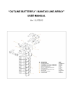
Portable Multifunction CalibratorMC141
Powertek
Content
Operation manual
1
Basic information
3
Preparation for operation
4
Content inspection
4
Power line voltage setting
4
Switch on
4
Warm-up time
5
Fuse replacement
5
Safety precautions
5
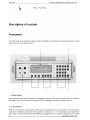
Description of controls
6
Front panel
6
Rear panel
9
Control of the calibrator
10
Selection of function
10
Output signal value
10
Relative deviation
11
Connection / disconnection of output terminals
12
Setting the frequency
13
Generation of calibrated voltage
14
Generation of calibrated current
16
Generation of non-harmonic shapes
17
Resistance
18
Generation of frequency
19
Simulation of RTD temperature sensors (Option RTD)
19
Simulation of TC temperature sensors
21
Setup menu
23
Calibration mode
26
Error messages
35
Calibrator’s maintenance
36
Verification test
37
Interface
42
IEEE-488 bus properties
Operation manual
42
ver 22
1
Powertek
Portable Multifunction CalibratorMC-141
RS232 serial line setting
42
Command syntax
43
Standard Status Data Structures
52
Examples of use
55
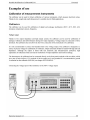
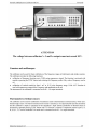
Calibration of measurement instruments
Multimeters
Counters and oscilloscopes
Thermometers (except sensor)
55
55
57
57
58
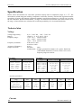
Specification
2
Operation manual
Portable Multifunction CalibratorMC141
Powertek
Basic information
MC-141 Multifunction Calibrator is a multifunction calibrator for use primarily as a mean of
calibration in calibration laboratories. It can be used for calibration of any measuring instrument, which
measures voltage, current, resistance and frequency. It generates harmonic and non-harmonic signals with
accurate amplitude. The calibrator includes a function of simulation of thermocouple temperature sensors
for testing of process meters.
Basic features of the calibrator includes generation of calibrated DC and AC voltage in the range
from 0 µV to 750 V, DC and AC current in the range from 0 µA to 2 A. Maximum precision of the
calibrator is 0.01 % for DC voltage, 0.055 % for AC voltage, 0.018 % for DC current and 0.075 % for AC
current. Maximum frequency range is 20 Hz to 1000 kHz. The calibrator is also source of fixed decade
resistance values in range from 10 Ω to 100 MΩ with accuracy 0.01 %. In frequency mode the calibrator can
generate squarewave signal in range from 0.1 Hz to 2 MHz
Simulation of temperature sensors is another feature that can be used to calibrate thermometers and
heat sensing units. The calibrator allows TC thermocouple temperature sensors of R, S, B, J, T, E, K, N
type. Compensation of cold junction of thermocouple is achieved by entering the respective temperature
using the calibrator’s keyboard. The accuracy of simulated temperature sensors depends on the value and
type of sensor and ranges and is from 0.1 oC to 4.3 oC . simulation RTD resistance temperature sensors of
Pt/Ni type and
The calibrator includes many other features which facilitate easy use. For example relative deviation from
set value of the output, currently displayed uncertainty of the output signal, calibration and testing
procedures etc. The concept of the calibrator control and indication of its status is based on flat LCD
display, which provides all necessary information. The calibrator is controlled by opening menus on the
display and selection from menus. Frequently used functions are assigned direct-control keys. The calibrator
is delivered with standard RS-232 serial line as standard (GPIB optionally), which allows the calibrator to
be controlled from a PC.
The calibrator can easily fit within calibration systems featuring MBASE/WinQbase software
support.
ATTENTION !
The calibrator generates life-threatening high voltage.
The calibrator can only be used in line with this Manual.
Operation manual v22
3
Portable Multifunction CalibratorMC141
Powertek
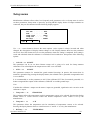
•
After the tests conclude, the calibrator resets to its reference state, i.e. the following
parameters are set:
Function
DC voltage
Range
10 V
Set value
10 V
Output terminals
OFF
Note. The calibrator resets to its reference status in case of power switching off and switching on.
Warm-up time
The calibrator works after it is switched on and the initial checks complete. Specified parameters are
guaranteed after the instrument warms up for 5 minutes. During this period, the instrument cannot be recalibrated. The display shows “cannot access the calibration” message if calibration is attempted during this
period.
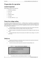
Fuse replacement
The calibrator includes a fuse located in the mains connector at the rear panel. Replace the fuse as follows:
•
Switch off the calibrator.
•
Remove the end of power cord from the mains connector at the rear panel.
•
•
Insert the blade of a flat screwdriver into the opening cut in the mains voltage selector and pull out
the fuse holder.
Remove the fuse and replace it with new fuse of the same rating.
Safety precautions
The instrument has been designed in Safety Class I according to EN 61010-1. The design reflects the
requirements of A2 amendment of the standard. Safety is ensured by the design and by the use of specific
component types.
The manufacturer is not responsible for a damage caused by modification of the construction or replacement
of parts with non-original ones.
Used safety symbols used on the instrument
Warning, reference to the documentation
Warning - risk of electric shock
Operation manual v22
5
Portable Multifunction CalibratorMC141
Powertek
active position in numerical value. With the rest two buttons (∧, ∨ ) value can be incremented or
decremented.
3
Numerical keyboard
Numerical values can be entered from the keyboard. For confirmation of set value ENTER button is
intended. With CANCEL button already set value can be cancelled.
4
Output terminal button
With ON/OFF button signal can be connected to the output terminals. Switching on the output terminals is
indicated with red LED diode in parallel with symbol ON or OFF displaying on the display.
5
Output terminals
Output signal of the calibrator is connected to the output terminals. Current ranges are connected to +I / -I
terminals. All other functions (voltage, resistance, frequency) are connected to Hi / Lo terminals.
GND terminal is located on the rear panel. It is connected to the protective terminal of the mains plug. Using
the SETUP MENU, item GND, the output terminals of the calibrator can be set as grounded or floated.
Grounding is done internally by connecting Lo and GND terminals using a relay. This circuit design is
suitable for most calibrations, when the object (multimeter) being calibrated is floating.
Between terminals following maximal voltages are allowed:
Hi - GND protection terminal (housing):
1000VRMS
+I - GND protection terminal (housing):
10VRMS
Lo - GND protection terminal (housing):
10VRMS
- I - GND protection terminal (housing):
10VRMS
6
POWER button
When the calibrator is switched off, it can be switched on by pushing the button POWER. When the
calibrator is switched on, it can be switched off be repeated pushing the same button. After the first pushing,
request to switch the button POWER again is displayed. When the button is switched the second time,
calibrator is switched off. If any other button is switched instead of POWER, calibrator is returned to the
last set mode.
7
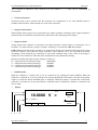
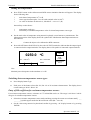
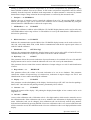
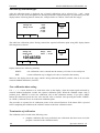
Display
10:07
10.0000 V =
OFF
Local
Gnd
∆% = 00.000 %
X10
a
b
c
d
Operation manual v22
:10
+/-
ACCURACY
0.0070
f
e
7
Powertek
Portable Multifunction CalibratorMC-141
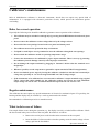
Display is graphically split into several fields, which display information about calibrator setting:
a)
Information field
It shows real time. Real time displaying can be canceled in SERVICE MENU.
b)
Main field
On the line, there is with double size numbers displayed main parameter of the calibrator output
signal, following with its unit. With the symbols ▼▲ there is indicated also active position of the
cursor. Cursor position can be set with cursor buttons <, > set value with the buttons ∧, ∨. Symbols
of active cursor are displayed after pushing any of cursor buttons.
c)
Auxiliary field
In two lines auxiliary parameters of the output signal are displayed. To these parameters belong:
•
•
•
d)
Set relative deviation in %
Frequency of AC voltage/current
Temperature of cold junction in TC temperature sensor simulation mode, type of TC sensor
Display button field
In the line labels related to the display buttons are shown. Meaning is as follows:
Symbol
Button function
Note
x 10
10 x increasing the value
for functions U, I, R, F
: 10
10 x decreasing the value
For functions U, I, R, F
Shape
Waveform selection
U, I functions
+/-
Polarity of output signal
For functions DC U, DC I
Calib
Enter to the calibration mode
Available in MENU
Type
TC sensor type setting
For temperature sensor
simulation
e) Information field
In the field some next information are displayed, which are related to the set function:
• Symbol of OUTPUT ON or OUTPUT OFF output terminals. In parallel LED diode is
turning on/off above the button ON/OFF.
• Information about local/remote control. In remote control label REM is displayed, in manual
mode label LOCAL is shown.
• Information about output current simulated by current coil Opt. 140-50, if the coil is
connected to the output current terminals. Access to this function is through SETUP
MENU.
• Information about grounding of Lo/-I terminals.
• Information about selected TC temperature sensor in mode TC sensor simulation.
f)
8
Uncertainty fiend
In the field there is displayed currently valid uncertainty of the main parameter of the output
signal. It is calculated from full specification of the calibrator and it is displayed in %.
Operation manual v22
Portable Multifunction CalibratorMC141
Powertek
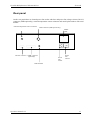
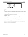
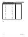
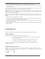
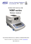
Rear panel
On the rear panel there are located power line socket with fuse and power line voltage selector, RS-232
connector (GPIB optionally), external temperature sensor connector and model plate number with serial
number.
External temperature sensor connector
RTD connector (RTD option only)
RS-232 connector GPIB connector
(optionally)
Power
line
socket
Model
plate
Power
line
selector
GND terminal
Operation manual v22
9
Powertek
Portable Multifunction CalibratorMC-141
Control of the calibrator
Selection of function
After the power is switched on and the initial checks complete, the calibrator resets to its reference
status, i.e. DC voltage output with set value of 10 V and output terminals disconnected. The status of the
calibrator can be changed using the buttons located at the front panel in one of the following ways:
1.
Change of function
By repeated pushing the button FUNC basic mode of the calibrator can be changed in the order DCV –
ACV – DCI – ACI - resistance – frequency – TC simulation – RTD simulation.
2.
Connection /disconnection of output terminals
After pressing the ON/OFF button, the output terminals of the calibrator are connected/disconnected.
3.
Entry to the setup menu
After pressing the SETUP button SETUP MENU appears on the display and the display buttons allow
the entry to the calibration mode (CALIB). Previous mode is restored by pressing the ESC display
button.
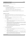
Output signal value
All function modes allow several methods of setting the main value of the output signal:
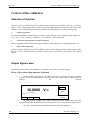
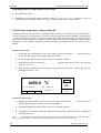
Entry of the value using numeric keyboard
•
use the numeric keyboard to select the desired value. After the first digit is entered,
symbols of unit of measurements are displayed above the display buttons. The monitor line
displays
the
symbols
[ _ _ _ _ _ _ _ _ ].
10.0000 V =
[ 11.2345 _ _ _ _ _ _ ]
∆% = 00.000 %
X10
•
•
10
:10
+/-
OFF
Local
Gnd
ACCURACY
0.0070
after the entry is complete (the value is displayed on the monitor line), press the
display button below the desired unit of measurement (V, mV or µV in the example below)
the value is copied to the main display and the monitor line disappears.
Operation manual v22
Portable Multifunction CalibratorMC141
Powertek
Entry of the value using cursor buttons
•
press <, >, ∧ or ∨ button. The display now includes cursor marks, which point to the
active digit.
•
∧ and ∨ buttons can be used to change the active digit. <, > buttons can be used to
change the position of the cursor marks
•
to get to the default screen, press ESC button or keep pressing the center cursor button
until there is no [ _ _ _ _ _ _ _ ] under any value. All values can be set using the buttons or
the potentiometer.
Reverse polarity
In DC voltage and DC current modes, the polarity of the output value can be reversed by pressing +/display button. „ - “ symbol appears in front of the main data value.
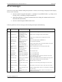
Relative deviation
All function modes of the calibrator except frequency mode allow a relative deviation of output value
from the main data to be set using a separate display. Relative deviation is displayed in the “auxiliary
field” section of the display and it is designated with „ ∆%= 00.0000 % “ symbol. The relative deviation
can be entered using one of the methods described above.
Setting relative deviation using numeric keyboard
•
keep pressing the center cursor button until [ _ _ _ _ _ _ _ ] symbols appear under
the relative deviation value in the “minor data” section of the display
•
enter the desired deviation and confirm the value by pressing “ % “ display button or
by pressing ENTER on the numeric keyboard
•
the auxiliary line below the main data on the display displays the total value of output
signal including the unit of measurement
the value of the signal at output terminals is:
the value indicated by the main display + ∆ %
the value indicated by the main display + ∆ oC
10.0000 V =
∆% = 00.000 %
[ 3.56 _ _ _ _ _ _ ] _
%
Operation manual v22
for voltage, current, frequency mode .
for TC sensor simulation
OFF
Local
Gnd
ACCURACY
0.0070
11
Powertek
Portable Multifunction CalibratorMC-141
Maximum relative deviation which can be entered is ± 30.000 %.
The deviation can be positive or negative. If negative deviation is desired, press the display button
labeled +/-. If positive deviation is then desired, press “ +/- “ button again. The polarity of the relative
deviation can be reversed using the cursor buttons or the potentiometer as well.
Setting relative deviation using cursor keys
•
keep pressing the button SEL until [ _ _ _ _ _ _ _ ] symbols appear under the relative
deviation value
•
press <, >, ∧ or ∨ button. The display now includes cursor marks which point to the
active digit
•
∧ and ∨ buttons can be used to change the active digit. <, > buttons can be used to
change the position of the cursor marks
•
to get to default mode press the button SEL until symbols [ _ _ _ _ _ _ _ ] are
displayed under any item. The same status can be achieved by pressing the button ESC.
If non-zero deviation is entered, also main value can be further changed. Output signal is always
recalculated from both these values.
Change of value by factor of ten
All functions except TC simulation of the calibrator allow the increase of the output value by 10 or
reduction of the output value by 10. If the change results in overflow or underflow of calibrator’s range,
an error message appears:
Value too large !
if the resulting value is too large
Value too small !
if the resulting value is too small
Range change
•
•
Press the display button labeled “ x10 “ if you want to increase the range, “ :10 “ to
decrease the range.
The main value shown on the display is increased 10x (reduced 10x)
In resistance function appropriate fix values are connected to the output terminals.
Connection / disconnection of output terminals
After switching on the output terminals are disconnected in all modes. Press the ON/OFF button to
connect the output signal to the terminals. Red LED above the OUTPUT button is lit and the
information field on the display shows the symbol ON .
Press the ON/OFF button again to disconnect the output terminals. Red LED goes off and the
information field on the display shows the symbol OF.
12
Operation manual v22
Portable Multifunction CalibratorMC141
Powertek
During mode change, output terminals are always disconnected. Output terminals are disconnected also
when changing between voltage and current ranges or when changing between AC and DC ranges is
performed.
Voltage over 100 V is indicated also with acoustic interrupted signal.
Setting the frequency
Frequency can only be selected in AC voltage mode, AC current mode and frequency mode. In each
mode the frequency has a slightly different meaning and the frequency is therefore set in a different
manner.
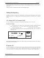
AC voltage (ACU), AC current (ACI)
Set value of frequency is shown in the Auxiliary field of the display in ACV, ACI modes.
Frequency change
•
First select the AC voltage or AC current mode by repetitive pressing the button
FUNC. Frequency value „f = xxx.xx Hz“ appears in the Auxiliary field of the display.
•
Press the button SEL until [ _ _ _ _ _ _ _ ] symbols appear under the frequency
value. Numeric keyboard can be used to enter the desired value. Press “ Hz “ or “ kHz “ to
confirm the value.
10.0000 V
∆% = 00.000 %
Hz
kHz
f = 100.000 Hz
[ 123.456 _ _ _ _ ]
SHAPE
OFF
Local
Gnd
ACCURACY
0.0070
If too large or too small value is entered, the calibrator displays the maximum (minimum) value which is
allowed for the selected function.
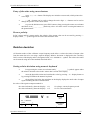
Frequency (F)
Set value of frequency is the main data on the display and the main parameter of the signal. Main data
can be set by direct entry using the numeric keyboard, potentiometer or by changing the digit at the
current cursor position. The setting procedure is described in the “Setting the value of output signal”.
Operation manual v22
13
Powertek
Portable Multifunction CalibratorMC-141
10.0000 kHz
OFF
Local
Gnd
∆% = 00.000 %
X 10
: 10
ACCURACY
0.0050
If frequency larger or smaller than the calibrator’s range is entered, the calibrator displays an error
message: „Value is too large (small)“.
Output waveform in frequency mode is always squarewave with TTL amplitude 0 – 5 V.
Generation of calibrated voltage
The multifunction calibrator provides calibrated DC and AC voltage. Output terminals for voltage
ranges are labeled “ Hi “ and “ Lo “ at the front panel. Depending on the setting of the calibrator,
voltage up to 750 Vef can be present at the terminals.
DC voltage range is from 0 to 750 V.
AC voltage range is from 100 µV to 750 V.
Output voltage up to 20 V is available at AUXILIARY connector (pins 3, 4) as well.
Control in the voltage mode
•
Press FUNC button on the calibrator until DC or AC voltage mode will appears. The
display shows the following data:
*
*
*
*
•
•
•
•
14
main data of set voltage
relative deviation
uncertainty of output voltage
frequency (when AC voltage is generated)
Set the desired value of voltage, including polarity when necessary, frequency and
relative deviation. The signal is yet not connected to the output terminals. The information section
of the display shows the symbol OFF which informs about the disconnection of output terminals.
Press ON/OFF button.
Red LED is lit above the OUTPUT terminals to signal the connection of the signal to
the output terminals; the information section of the display shows the symbol ON.
Calibrated voltage corresponding to set parameters is present at the output terminals.
Operation manual v22
Portable Multifunction CalibratorMC141
Powertek
Control sequence when output voltage over 100 V is selected
When output voltage over 100 V is selected, the information section of the display shows the symbol
which informs that a life-threatening voltage will be present at the output terminals. If the output
terminals are currently connected, they will be disconnected when output voltage over 100 V is selected.
ON/OFF button must be pressed to reconnect the output signal to the output terminals. After the
ON/OFF button is pressed, an interrupted beep is sound, OUTPUT LED is lit and the information
section of the display shows the symbol notifying the user about the connection of the dangerous output
signal to the output terminals.
Voltage, polarity, frequency, absolute and relative deviation can be set without the outputs being
disconnected. The output terminals are automatically disconnected when changing between AC and DC
ranges or when changing the function mode.
Overloading of terminals
If the output terminals are overloaded or short-circuited in the voltage mode, the calibrator disconnects
the signal from the output terminals and reports „Overload U output“ error.
ATTENTION DANGEROUS
VOLTAGE
When working with voltages over 50 V, rules for work with
dangerous voltage must be adhered to.
Never touch the measurement circuit when voltage over 50 V
is set and output terminals are connected!
ATTENTION DANGEROUS
VOLTAGE
When the calibrator is controlled remotely, it is not possible
to disconnect the output voltage using the buttons located at
the front panel!
The calibrator must be first switched to local control mode by
pressing the LOCAL button and then the output terminals
can be disconnected or the mains switch must be switched off
!
Operation manual v22
15
Powertek
Portable Multifunction CalibratorMC-141
Generation of calibrated current
The multifunction calibrator provides calibrated DC and AC current. Output terminals for voltage
ranges are labeled “ +I “ and “ -I “ at the front panel. The terminals can carry high current and are the
only terminals to which the calibrated object can be connected. Depending on the setting of the
calibrator, current up to 2 Aef can be driven by the terminals.
DC current range is 0 to 2 A
AC current range is 1µA to 2 A
When 50-turn coil (option 140-50) is used, maximal simulated AC current is 100 A.
Control in the current mode
•
Press the button FUNC until AC or DC current mode will appear. The display shows the following
data:
main data of set current
relative deviation
uncertainty of output current
frequency (when AC current is generated)
•
Set the desired value of current, including polarity when necessary, frequency and relative deviation.
The signal is yet not connected to the output terminals. The information section of the display shows
the symbol OFF which informs about the disconnection of output terminals.
•
Connect the load or short the output terminals labeled +I, -I.
•
Press OUTPUT button.
•
Red LED is lit above the OUTPUT terminals to signal the connection of the signal to the output
terminals; the information section of the display shows the symbol ON.
•
Calibrated current corresponding to set parameters is driven by the output terminals.
•
If COILx50 function is activated (see below - Setup functions menu), the optional 50-turn coil must
be connected to output terminals. The calibrator can be used to calibrate clamp ammeters to 100 A
ammeters.
CAUTION
If GND terminal is connected to Lo, -I terminals, it is
prohibited to connect external load to GND / Hi or GND / +I
terminals. Such connection can damage the calibrator.
16
Operation manual v22
Portable Multifunction CalibratorMC141
Powertek
Overloading the terminals
When external circuit connected to current output terminals is disconnected or there is higher voltage at
the load than permitted, the calibrator disconnects the output terminals and displays „Overload I output“
message. The same message can be displayed when 50-turn coil is used for AC current output at
frequencies above 80 Hz. It depends on the set current and the type of ammeter connected.
Generation of non-harmonic shapes
The multifunction calibrator can generate non-harmonic periodic signals with predefined shape. To
allow the setting of a non-harmonic output shape, the calibrator must be switched to ACV or ACI mode.
In both cases, an indication of the type of output shape is displayed beside the main set value. Press the
display button SHAPE to change the shape of the output signal.
The calibrator can generate the following shapes:
•
•
•
•
•
•
SINE
PWM SYM
RAMP A
RAMP B
TRIANGLE
LIM SINE
k=13.45%
sinus (harmonic)
squarewave - symmetrical, with adjustable duty cycle
ramp, symmetrical positive
ramp, symmetrical negative
triangular, symmetrical
sinus with amplitude limitation (truncated sin) with defined distortion
Generation of non-harmonic signals has some limitations:
•
•
non-harmonic signals can be generated in frequency range 20 Hz to 80 Hz
maximal non-harmonic current is 2A, maximal voltage is 10V
Control in the non-harmonic mode
•
Select AC voltage or AC current mode. The main section of the display shows the following data:
*
*
*
*
•
main data of set current or voltage, unit of measurement
relative deviation
frequency
selected SHAPE of the output signal
Keep pressed SHAPE display button to select the desired shape of the output signal:
The output terminals are automatically disconnected when the shape of the output signal is changed.
Relative deviation is reset.
Displayed information
When non-harmonic output shape is selected, the display shows additional information:
Operation manual v22
17
Powertek
Portable Multifunction CalibratorMC-141
•
Besides the main amplitude data, „pk“ index is displayed, notifying that the displayed main value is
the peak value.
•
Symbol which displays the shape of the output signal is displayed.
OFF
10.0000 Vpk Λ
∆% = 00.000 %
X 10
: 10
Local
Gnd
f = 80.000 Hz
ACCURACY
0.30
Shape
Resistance
Multifunction calibrator is equipped with fix resistance positions values with decade nominal values.
The positions are created with stable resistors. Their value cannot be adjusted. The resistance feature is
available on Hi – Lo terminals in two-wire connection.
Resistance range is 10, 100, 1k, 10k, 100k, 1M, 10M, 100M Ω.
Control in the resistance mode
•
Press FUNC button until resistance function will appear. The display shows the set resistance.
calibration value of set resistance in Ω
uncertainty of the resistance
•
To change the resistance value press the display button x10 or :10.
•
Press the button ON/OFF to connect the resistance to the output terminals.
•
Red LED is lit above the ON/OFF button and indicates that the resistance is connected to the output
terminals.
10.0059 kΩ
X 10
: 10
OFF
Local
Gnd
ACCURACY
0.015
Resistance mode is suitable for use in DC applications and AC applications to 10 kHz.
18
Operation manual v22
Portable Multifunction CalibratorMC141
Powertek
Generation of frequency
Multifunction calibrator can generate squarewave TTL leveled signal with 4 digit resolution frequency.
The signal is available in frequency mode on output terminals Hi – Lo. Frequency range is from 0.1 Hz
to 2 MHz.
Control in the frequency mode
•
Press FUNC button until frequency mode is selected.. The display shows following data:
*
*
set frequency as main parameter
relative deviation of frequency
*
uncertainty of frequency
•
Set the frequency using numeric keyboard, cursor buttons or potentiometer. Output signal is not yet
connected to the output terminals.
•
Connect the object to be calibrated to FREQ terminal.
•
Press ON/OFF button. Red LED is lit above the OUTPUT terminals to indicate the connection of
signal to the output connector.
10.0000 kHz
OFF
Local
Gnd
∆% = 00.000 %
X 10
: 10
ACCURACY
0.0050
Note:
Output impedance in frequency mode is 50 Ohm on Hi – Lo terminals.
Simulation of RTD temperature sensors (Option RTD)
Multifunction calibrator can simulate optionally resistance (RTD) temperature sensors.
When resistance temperature sensors are simulated appropriate resistance with value corresponding to
set temperature is connected to the output terminals on rear panel connector RTD. Connection is fourwire type. Use connector attached to the delivery to connect unit under test to RTD connector.
-250 to +850 oC for Pt temperature sensors
-60 to +300 oC for Ni temperature sensors
ITS 90, PTS 68
Temperature scale:
Rear panel RTD connector connection:
Pin 1 - Li, Pin 2 – Lu, Pin 3 – Hi, Pin 6 - Hu
Temperature setting range:
Operation manual v22
19
Powertek
Portable Multifunction CalibratorMC-141
Setting the temperature
•
Press FUNC button on the calibrator until RTD sensor simulation function will appear. The display
shows following data:
*
*
*
main data of temperature in oC or K
sensor type thermocouples: Pt or Ni with nominal value in 100 oC
set value of absolute deviation in %, labeled ∆T = xxxx.x °C (K)
the auxiliary section shows:
*
*
•
Set the main value of temperature using numeric keyboard, cursor buttons or potentiometer. The
information section of the display shows the symbol OFF which means that output terminals are
disconnected.
•
•
temperature scale type
uncertainty of simulated temperature value of selected temperature sensor type
Connect the object to be calibrated to RTD connector.
Press ON/OFF button. Red LED is lit above the OUTPUT terminal to indicate that the output signal
is connected to the output terminals. The display shows ON symbol of connected output terminals.
0250.0
o
∆T = 000.0 C
o
C
R0 = 100.0 Ohm
Type
Pt385
OFF
Local
Gnd
ITS90
ACCURACY
o
0.3 C
Note:
Maximal power dissipation in the simulator is 0.2 W.
Switching between temperature sensor types
•
Press Display button Type.
•
Each press of the button selects Pt1.385, Pt1.392 or Ni resistance thermometer. The display shows
current setting as Pt385 / Pt392 / Ni.
Entry of R0 coefficient for resistance temperature sensors
For resistance temperature sensors, resistance at 0 oC labeled R0 can be set. The range is 100 Ω to 1 kΩ for
all types of resistance temperature sensors.
20
•
Select the resistance temperature sensor mode and keep pressing the center cursor button until [ _ _
_ _ _ _ _ ] symbols appear under the R0 coefficient value (R0 = xxxx Ω).
•
Set the value using numeric keyboard and confirm by pressing “ Ω” display button or by pressing
ENTER.
Operation manual v22
Portable Multifunction CalibratorMC141
Powertek
Simulation of TC temperature sensors
When thermocouples are simulated, the simulated voltage corresponding to set temperature, sensor type
and temperature of cold end of thermocouple is connected to Hi - Lo terminals.
Temperature setting range: -250 to +1820 oC depending on simulated sensor type
Sensor types:
thermocouple K, N, R, S, B, J, T, E
Temperature scale:
ITS 90, PTS 68
Setting the temperature
•
Press FUNC button on the calibrator until TC sensor simulation will appear. The display shows
following data:
*
*
*
*
main data of temperature in oC or K
sensor type thermocouples: K, N, R, S, B, J, T, E
cold junction temperature of thermocouple sensors RJ
set value of absolute deviation in %, labeled ∆T = xxxx.x °C (K)
the auxiliary section shows:
*
*
temperature scale type
uncertainty of simulated temperature value of selected temperature sensor type
•
Set the main value of temperature using numeric keyboard, cursor buttons or potentiometer. Output
terminals are disconnected. The information section of the display shows the symbol OFF which
means that output terminals are disconnected.
•
Connect the object to be calibrated to Hi - Lo terminals.
•
Press ON/OFF button. Red LED is lit above the OUTPUT terminal to indicate that the output signal
is connected to the output terminals. The display shows ON symbol of connected output terminals.
0450.0
o
o
OFF
C
o
∆T = 000.0 C
Type
RJ = 0000.0 C
[________ ]
TC type K
Local
Gnd
ITS90
ACCURACY
o
0.3 C
Note:
Current capability in TC sensor simulation mode is 5 mA.
Operation manual v22
21
Powertek
Portable Multifunction CalibratorMC-141
Switching between temperature sensor types
•
Press the button TYPE.
•
Calibrator switches among thermocouples in order K, N, R, S, B, J, T, E. Currently set type of
thermocouples is displayed in form TC TYPE x, where x means type of thermocouple.
Cold junction temperature compensation RJ
Temperature of cold junction can be compensated either manually or automatically. If manual mode is
selected, temperature of cold junction is entered from front panel keyboard. If automatic compensation
is selected, calibrator measure via internal Pt temperature meter the temperature of output terminals,
displays the measured value and compensate output voltage related to the set temperature with measured
temperature of the terminals. Switching between automatic and manual mode is one item in service
MENU.
Manual compensation
•
By pushing the button MENU open servuci menu. With cursor buttons ∨, ∧ select position RJ
Temp. and with display buttons select parameter FIXED.
•
By repeated pushing the button FUNC select TC simulation function.
•
Push the button SEL until symbol [ _ _ _ _ _ _ _ ] appears under the RJ value. RJ value has
form RJ = xxxx.x oC.
•
Write requested temperature of cold junction using numerical keyboard . Confirm the value by
pushing the button oC (K).
0450.0
∆% = 00.000 %
o
C
o
OFF
C
o
RJ = 0023.0 C
[__________]
TC type K
Local
Gnd
ITS90
ACCURACY
o
0.3 C
Automatic compensation
•
Pushing the button MENU open service menu. With cursor buttons ∨, ∧ select function RJ
Temp. and with display buttons select parameter MEAS.
•
By repeated pushing the button FUNC select TC simulation function.
•
Temperature of the output terminals is displayed in the field RJ. Output voltage is compensated
with measured value.
Note:
As sensor for measuring of ambient temperature external Pt1000 sensor is used. This sensor
is part of standard delivery. Sensor has to be connected to the connector on rear panel.
22
Operation manual v22
Portable Multifunction CalibratorMC141
Powertek
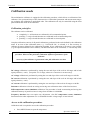
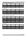
Setup menu
Multifunction calibrator allows other, less frequently used parameters to be set. Setup menu is used to
set these parameters. Setup menu is opened by pressing MENU display button. If output terminals are
connected, they are disconnected and the following display appears:
Coil x50 . . . . . . OFF
Gnd . . . . . . . . ON
Temp. scale
. . . ITS90
o
Temp. unit . . . . . .
C
RJ Temp. . . . . . FIXED
Calib
Use ∧ or ∨ cursor button to browse the menu options. Active option is always inverted and when
changed, the descriptions of display buttons change as well. Display buttons show how the parameter
can be set. Press ESC button twice to save the parameters when new setting is completed. New setting is
saved and refreshed when the calibrator is switched off and switched on. Setup menu offers following
options:
1. Coil x50 .... xx ON/OFF
This parameter can be set on when 50-turn current coil is going to be used for clamp ammeter
calibration. The coil multiplies the output current. OFF is set as default.
2. GND .... xx
ON/OFF
This parameter connects Lo terminal the groud terminal (housing). In practice this means that Lo
terminal is grounded. By pressing the display buttons, the terminal can be grounded or ungrounded. ON
is set as default.
It is recommended to set the parameter to ON. If the calibrated UUT has Lo terminal grounded, it is
better to unground the outputs of the calibrator, GND OFF to exclude ground loops.
Note:
If neither the calibrator’s output nor the meter’s inputs are grounded, signal/noise ratio can arise at the
calibrator’s output.
3. Temp.scale .... xx
ITS90/PTS68
This parameter allows the temperature scale for temperature sensors to be selected. Pressing the display
buttons allows to switch between ITS90 and PTS68 temperature scales. ITS90 is set by the
manufacturer.
4. Temp.unit .... xx
o
C/K
This parameter allows the temperature unit for simulation of temperature sensors to be selected.
Pressing the display buttons allows to switch between °C and K. °C is set by the manufacturer.
5. RJTemp. .... xx
Operation manual v22
FIXED/MEAS.
23
Powertek
Portable Multifunction CalibratorMC-141
Setting of method of cold junction temperature of TC sensors compensation. By pushing the display
button FIXED or MEAS item can be chosen. In FIX mode cold junction temperature must be entered
manually from the keyboard. In MEAS mode temperature of output terminals is measured by internal
thermometer. Output voltage related to the set temperature is corrected by the measured value.
6. Interface .... xx GPIB/RS232
Displays the type of interface used to control the calibrator from a PC. By pressing GPIB or RS232
buttons, the respective type can be selected. The calibrator can be remotely controlled only using the
selected interface. GPIB interface is delivered as option only.
7. GPIB address .... xx
UP/DOWN
Displays the calibrator’s address at the GPIB bus. UP, DOWN display buttons can be used to select any
valid GBIP address in the range of 00 to 30. The address 02 is set by the manufacturer. GPIB interface is
delivered as option only.
8. RS232 baud rate .... xx UP/DOWN
Indicates the communication speed of RS232 bus. UP/DOWN display buttons can be used to select 150,
300, 600, 1200, 2400, 4800, 9600, 19200. Perfect communication with the PC requires equal values set
at the PC and the calibrator.
9. Handshake .... xx
OFF/Xon-Xoff
Indicates the communication handshake. Display buttons can be used to select OFF or Xon/Xoff. Perfect
communication with the PC requires equal values set at the PC and the calibrator.
10. Keyb.beep .... xx
ON/OFF
This parameter allows the acoustic indication of pressed buttons to be switched off or on. ON and OFF
display buttons can be used to switch the indication off or on. ON is set by the manufacturer.
This parameter does not control the acoustic indication of output voltages over 100 V and identification
of errors.
11. Beep.volume .... xx
HIGH/LOW
This parameter allows the volume of acoustic indication to be set in two loudness. This parameter
controls the volume of keyboard beep (if switched on), indication of output voltages over 100 V and
identification of errors when controlling the calibrator.
12. Display .... xx
UP/DOWN
This parameter sets the uderlightning of the display. Positions always OFF, OFF 30s after last pushing a
button, OFF 300s after the last pushing a button, permanently ON is offered.
13. Contrast .... xx
UP/DOWN
Setting the contrast of the display. BY pushing the display button higher or low contrast can be set in
range 00 to 31.
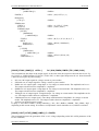
14. Cal.code .... 000000
Access to the calibration code. Calibration code is a five-digit number, which must be entered to access
the calibration mode. If the calibration code is set to “000000”, this information is displayed in the Setup
menu. Calibration code can be changed. New calibration code can be directly entered using numeric
keyboard and confirmed by pressing ENTER. If non-zero calibration code is set, correct calibration code
must be entered to access the calibration mode. Non-zero calibration code is not displayed further on the
display.
24
Operation manual v22
Portable Multifunction CalibratorMC141
Contrast
Cal. code.
Cal. date
Serial No
Time . .
.
.
.
.
.
.
.
.
Powertek
.
.
.
.
. . . OFF
. 000000
. 01.2003
. . xxxxxx
. . . .
16:54
Calib
The purpose of the calibration code is to prevent unauthorized users from changing the calibration of the
instrument.
Note:
It is advisable to write down actual calibration code if changed. If you forget the calibration code, you
have to send the calibrator to the manufacturer.
15. Cal.date .... xx.yyyy
Displays the date of last calibration of the calibrator (month/year). The parameter cannot be changed, as
it is automatically recorded when leaving the calibration mode.
16. Serial No .... xxxxxx
Displays the serial number of the calibrator. The parameter cannot be changed.
17. Time .... xx:yy
Displays real time. The parameter can be changed using HOUR, MIN +, MIN - display buttons.
18. Date .... xx.yy.zzzz
Displays real time. The parameter can be changed using DAY, MONTH, YEAR display buttons.
19. Time on display .... xx ON/OFF
If the item is set to ON, time and date are displayed in the upper part of the display. If OFF is set, time
and date are not displayed. ON is set by the manufacturer.
Operation manual v22
25
Powertek
Portable Multifunction CalibratorMC-141
Calibration mode
The multifunction calibrator is equipped with calibration procedure, which allows re-calibration of the
calibrator. Zero point and slope of the characteristics of individual generation and measurement ranges
are set during the calibration in predefined order. The calibration can only be controlled using the front
panel buttons and menu on the calibrator.
Calibration principles
The calibrator can be calibrated:
•
•
•
completely, i.e. all functions are calibrated in all recommended points
partially, i.e. only selected functions are calibrated in all recommended points
partially, i.e. only selected functions are calibrated in selected points
Complete calibration consists of all partial calibrations performed in the order defined by the calibration
menu. If an item of the calibration menu, e.g. “VOLTAGE DC” is selected, it is not necessary to
calibrate all ranges defined by the calibration algorithm. If new calibration of all ranges is not possible
(e.g. the required standard is not available), old calibration data can be confirmed, i.e. current step of the
Calibration interruption can be performed in any point of the calibration
procedure. However this particular calibration influences parameters of the
calibrator.
Accuracy of the calibrator is guaranteed when full calibration was done.
calibration can be skipped.
DC voltage calibration is performed by setting the zero and slope of the scale in all ranges and in both
signal polarities (+ and -) (except the 750 V range, where zero correction is not necessary).
AC voltage calibration is performed by setting the zero and slope of the scale in all ranges at 100 Hz.
DC current calibration is performed by setting the zero and slope of the scale in all ranges and in both
signal polarities (+ and -).
AC current calibration is performed by setting the zero and slope of the scale in all ranges at 100 Hz.
Resistance calibration is based on writing and saving new calibration values of the fixed resistors.
RTD temperature sensor simulation calibration. The procedure is based on measuring and saving into
calibration memory of partial resistors in range from 20 Ohm to 120 MOhm.
Frequency function does not require any adjustment. Also TC temperature sensor simulation
function need no other adjustment as it is calculated from DC voltage ranges 10 and 100 mV.
Access to the calibration procedure
Calibration code is required to access the calibration procedure.
•
26
Press MENU button to open the setup menu.
Operation manual v22
Portable Multifunction CalibratorMC141
Powertek
•
Press CALIB display button.
•
If an attempt is made to access the calibration procedure within 60 minutes after the calibrator
was switched on, the calibrator refuses to open the calibration menu and displays following
message:
Err 21 Time warm up !
If the calibrator is already switched on for at least 60 minutes, it requests calibration code.
OFF
Set Calibration code
[ 000000 ]
Local
Gnd
•
Enter correct calibration code using numeric keyboard and press ENTER.
•
If incorrect calibration code is entered, an error message appears on the display for
approximately 3 seconds:
Err 20
Bad calib. code!
•
If correct calibration code is entered, calibration menu will appear:
Voltage DC
Voltage AC
Current DC
Current AC
Resistance
OFF
Local
Gnd
Sel.
•
1.
2.
3.
4.
5.
Use ∧ and ∨ cursor buttons to move the cursor through the list:
VOLTAGE DC
VOLTAGE AC
CURRENT DC
CURRENT AC
RESISTANCE
Operation manual v22
All DC voltage ranges calibration
All AC voltage ranges calibration
All DC current ranges calibration
All AC current ranges calibration
Resistance calibration
27
Powertek
Portable Multifunction CalibratorMC-141
Selection of calibration type
After the calibration menu is displayed, any of partial calibrations can be selected. Use ∧ and ∨ cursor
buttons to move the cursor through the list. Having selected the required function to be calibrated, press SEL
display button. Following data are shown (the example bellow is valid for VOLTAGE DC range):
Voltage DC
Range 10 mV
OFF
+0mV
- 0mV
+10 mV
- 10 mV
+ 0 mV
Local
Gnd
Sel.
The table lists calibration points. Having selected the required calibration point using SEL display button
following data are shown.
Voltage DC
Range 10 mV
▼
Range
Value
10mV
+ 10 mV
10146350
OFF
Local
Gnd
▲
Write
Skip
Display buttons have following meaning:
WRITE
new calibration value is entered into the memory, old value is irreversibly lost
SKIP
current calibration step is skipped, old value is retained in the memory
Moreover, the display shows the range which is being calibrated (RANGE), and the value to be set at the
external standard multimeter (VALUE).
New calibration data setting
Use ∧, ∨, <, > cursor buttons to set such main value on the display, when the output signal measured by
external standard multimeter reaches the required calibration point. When the standard output value is
reached, press “WRITE” to write new calibration value to the calibration memory. If you press “SKIP”
button, the calibrator ignores the new value and old value is retained. After pressing the button “WRITE”
(or “SKIP”), calibrator moves on to the next calibration point.
The procedure is repeated for all calibration points of the selected function. If the button ESC is pressed
before completing the calibration, the calibrator returns to the basic calibration menu.
Termination of calibration
The calibration can be closed in the following cases:
•
28
complete calibration has been performed, new calibration data have been saved, the
program is returned to the calibration menu,
Operation manual v22
Portable Multifunction CalibratorMC141
Powertek
•
calibration of selected function and selected ranges has been performed, new calibration data have
been saved, the program is returned to the calibration menu,
•
the calibration has been started but no calibration data have been entered, the program is returned to
the calibration menu after ESC display button has been pressed.
Press ESC display button to terminate the calibration. The calibrator returns to the state it was in before the
calibration has been started.
Calibration points
Each function contains fixed calibration points which have to be set during the calibration. For VOLTAGE
DC, VOLTAGE AC, CURRENT DC, CURRENT AC the output signal value is set using the keyboard. For
RESISTANCE function calibration data of the fixed resistances must be entered. T function does not require
any calibration, as the output voltage or resistance is based on arithmetic interpolation using standard tables
of temperature sensor values.
VOLTAGE DC
Nominal value [V]
+0.0
- 0.0
+10 m
- 10 m
+ 0.0
- 0.0
+100 m
- 100 m
+ 0.0
- 0.0
+1.0
-1.0
+ 0.0
- 0.0
+10
- 10
+10
- 10
+100
- 100
+750
- 750
Table DCV
Operation manual v22
Tolerance [V]
Range [V]
Note
2u
2u
4u
4u
2u
2u
6u
6u
5u
5u
12 u
12 u
20 u
20 u
100 u
100 u
200 u
200 u
600 u
600 u
20 m
20 m
10 m
-10 m
10 m
-10 m
100 m
-100m
100 m
-100m
1
-1
1
-1
10
-10
10
-10
100
-100
100
-100
750
-7500
zero calibration
zero calibration
slope calibration
slope calibration
zero calibration
zero calibration
slope calibration
slope calibration
zero calibration
zero calibration
slope calibration
slope calibration
zero calibration
zero calibration
slope calibration
slope calibration
slope calibration
slope calibration
slope calibration
slope calibration
slope calibration
slope calibration
29
Powertek
Portable Multifunction CalibratorMC-141
VOLTAGE AC
Nominal value [V]
1m
10 m
10 m
100 m
100 m
1.0
1.0
10
10
100
100
750
Table ACV
Tolerance [V]
Range [V]
Frequency[Hz]
5u
10 u
15 u
40 u
30 u
100 u
200 u
1m
5m
10 m
50 m
50 m
10 m
10 m
100 m
100 m
1
1
10
10
100
100
750
750
100
100
100
100
100
100
100
100
100
100
100
100
To calibrate ACV function is possible also on another set frequency. Specification in whole frequency range
is guaranteed only when recommended frequency is used.
CURRENT DC
Nominal value [A]
+0.0
- 0.0
+190 u
- 190 u
+200 u
- 200 u
+1.9 m
- 1.9 m
+2 m
-2m
+19 m
- 19m
+20
- 20
+190 m
- 190 m
+200
- 200
+1.9
- 1.9
Table DCI
30
Tolerance [A]
Range [A]
Note
3n
3n
5n
5n
20 n
20 n
50 n
50 n
100 n
100 n
200 n
200 n
1u
1u
2u
2u
20 u
20 u
50 u
50 u
200 u
-200 u
200 u
-200 u
2m
-2 m
2m
-2 m
20 m
-20 m
20 m
-20 m
200 m
-200 m
200 m
-200 m
2
-2
2
-2
zero calibration
zero calibration
slope calibration
slope calibration
zero calibration
zero calibration
slope calibration
slope calibration
zero calibration
zero calibration
slope calibration
slope calibration
zero calibration
zero calibration
slope calibration
slope calibration
zero calibration
zero calibration
slope calibration
slope calibration
Operation manual v22
Portable Multifunction CalibratorMC141
Powertek
CURRENT AC
Nominal value [A]
10 u
190 u
200u
1.9 m
2.0 m
19 m
20 m
190 m
200 m
1.9
Table ACI
Tolerance [A]
Range [A]
Frequency [Hz]
5n
50 n
40 n
200 n
200 n
2u
2u
20 u
20 u
200 u
200 u
200 u
2m
2m
20 m
20 m
200 m
200 m
2
2
100
100
100
100
100
100
100
100
100
100
To calibrate ACV function is possible also on another set frequency. Specification in whole frequency range
is guaranteed only when recommended frequency is used.
RESISTANCE
Nominal value [Ω]
10
100
1k
10 k
100 k
1M
10 M
100 M
Table R
Tolerance [Ω]
Range [Ω]
0.01
0.005
0.005
0.005
0.005
0.01
0.01
0.01
10 – 50
10 – 50
10 – 50
50 - 100
50 - 100
50 - 100
100 – 400
100 – 400
Standard multimeter should be connected in four terminals way to the output terminals Hi-Lo.
Operation manual v22
31
Powertek
Portable Multifunction CalibratorMC-141
RTD TEMPERATURE SENSOR SIMULATION
Nominal calibration point
[Ω ]
SHORT
20
40
80
150
300
600
1k1
2k2
4k4
8k8
16k
33k
66k
125k
250k
500k
1M
2M
4M
8M
16M
30M
60M
120M
Table R
Nominal resistance value
[Ω ]
0-0.2 Ohm
20
40
75
150
300
590
1k15
2k19
4k37
8k6
16k7
33k
65k
129k
253k
503k
1M
2M
4M
7M8
15M6
30M
59M7
118M
Tolerance [%]
In column Tolerance requested accuracy of measurement of the resistance segment is shown. Standard
multimeter has to be connected in four terminals way to the output terminals Hi-Lo for values bellow 10
kOhm.
32
Operation manual v22
Portable Multifunction CalibratorMC141
Powertek
Full calibration procedure
Following pages describe procedure of the full calibration.
Required instruments:
Following instruments are required for calibration:
•
81/2 digit multimeter type HP3458A or Wavetek 1281 or Fluke 8508A or other type with
accuracy 0.002 % or better on DC voltage
•
Resistance shunt 100 mΩ Burster 1280, or other type with accuracy 0.01%
•
Counter HP 53181A, HO 53130, BM 642 or other with accuracy 0,001 %
HP8903A Distortion analyzer and scope with bandwidth min. 20 MHz are recommended for THD
measuring of AC signals.
Calibration procedure
1.
Switch calibrator and standard multimeter on for at least three hours in laboratory at 23±1 oC.
2.
Press MENU display button to call up the setup menu and then CALIB display button to call up the
calibration menu.
3.
Enter the calibration code and press ENTER (default calibration code is “000000”).
4.
DC voltage ranges calibration
5.
a)
Connect the voltage input terminals of the multimeter to the Hi - Lo calibrator output
terminals.
b)
Select VOLTAGE DC from the calibration menu and confirm by pressing SEL button.
c)
Switch MC-141 output terminals ON.
d)
Follow the instructions provided on the calibrator display. Refer to the DCV table in chapter
Calibration points adjust the output level of the calibrator to meet nominal value displayed
on the standard multimeter. Use predefined calibration points.
e)
To adjust the output level in the calibration points use <, >, ∨, ∧ cursor buttons. Confirm
set value by pressing WRITE display button. If you want to skip the calibration point whose
calibration you have already entered, press SKIP display button.
f)
Switch output terminals OFF
AC voltage ranges calibration
a)
Select VOLTAGE AC from the calibration menu and confirm by pressing SEL button.
b)
Switch MC-141 output terminals ON.
c)
Follow the instructions provided on the display and the ACV table to adjust the calibrator
output in the calibration points.
d)
To adjust the output level in the calibration points use <, >, ∨, ∧ cursor buttons. Confirm set
value by pressing WRITE display button. If you want to skip the calibration point whose
calibration you have already entered, press SKIP display button.
e)
Switch output terminals OFF. Disconnect multimeter and calibrator.
Operation manual v22
33
Powertek
6.
7.
8.
9.
34
Portable Multifunction CalibratorMC-141
DC current ranges calibration
a)
Connect current input terminals of the multimeter to the +I - -I output terminals of the
calibrator. Select CURRENT DC from the calibration menu.
b)
Select DC current measurement range on the standard multimeter by pressing the button
SEL. Switch output terminals ON.
c)
Follow the instructions provided on the display and the DCI table to adjust the calibrator
output in the calibration points.
d)
To adjust the output level in the calibration points use <, >, ∨, ∧ cursor buttons. Confirm set
value by pressing WRITE display button. If you want to skip the calibration point whose
calibration you have already entered, press SKIP display button.
e)
Resistance shunt 100 mOhm should be used on 2A range, if standard multimeter does not
cover this range with required accuracy.
f)
Switch output terminals OFF.
AC current ranges calibration
a)
Select CURRENT AC from the calibration menu. Set the same function on external
multimeter.
b)
Follow the instructions provided on the display and the ACI table to adjust the calibrator
output in the calibration points.
c)
To adjust the output level in the calibration points use <, >, ∨, ∧ cursor buttons. Confirm set
value by pressing WRITE display button. If you want to skip the calibration point whose
calibration you have already entered, press SKIP display button.
d)
Resistance shunt 100 mOhm should be used on 2A range, if standard multimeter does not
cover this range with required accuracy.
e)
Switch output terminals OFF. Disconnect multimeter and calibrator.
Resistance ranges calibration
a)
Select RESISTANCE function in calibration menu by pressing the button SEL.
b)
Set Resistance function on the standard multimetr, select 4W method. Make short on the
standard multimetr terminals to correct zero if necessary.
c)
Select fixed resistance values on the calibrator from 10 Ohm to 100 MOhm and measure
them by standard multimeter. Write measured values from the numerical keyboard to the
calibrator. New calibration value confirm by pressing the button WRITE.
RTD temperature sensor simulation
a)
Select RTD temperature sensor function in calibration menu by pressing the button SEL.
b)
Set Resistance function on the standard multimetr, select 4W method for values bellow
10kOhm. Make short on the standard multimetr terminals to correct zero if necessary.
c)
Select partial resistance segments in the calibrator from 20 Ohm to 120 MOhm and measure
them by standard multimeter. Write measured values from the numerical keyboard to the
calibrator. New calibration value confirm by pressing the button WRITE.
Operation manual v22
Portable Multifunction CalibratorMC141
Powertek
Error messages
If an error occurs in the calibrator during the operation or control, error message is displayed on the display.
Errors can be caused by:
•
incorrect control using the front panel, i.e. attempts to set prohibited mode, e.g. setting an outof-range value, overloading of output terminals etc.,
•
fault of the calibrator, e.g. internal communication error during the communication between
individual functional blocks,
•
incorrect control using the GPIB or RS-232 bus.
Following table lists all error messages, their meaning and simple troubleshooting.
Error
No
Error message
Meaning
Solution
01
Overload 1V !
Overloading of voltage
output on range 1V
Output current is too high. Increase load resistance.
02
Overload 10V !
Overloading of voltage
output on range
10V/100V/750V
Output current is too high. Increase load resistance.
04
Overload I output ! Overloading of current
output
Voltage across external load is too high. Decrease load
resistance.
10
Interface error !
Remote connection error
Enter correct data format on GPIB/RS-232.
11
Bad command !
Unknown command
GPIB/RS-232
Use only defined commands..
13
Over range !
Overcrossed range in
remote control mode
In remote control mode value out of allowed limits was send to
the calibrator. Enter correct value.
14
Communication
error
Communication error on
GPIB/RS-232
General communication error in remote control mode.
15
Check sum error !
Fail data loading into
internal memory
For service purpose only.
16
Interrupted !
Interrupted command
IEEE488.2
Enter full data format.
17
Unterminated !
Wrong syntax IEEE488.2
Enter correct data format.
18
Deadlocked !
Wrong syntax IEEE488.2
Enter correct data format.
20
Bad calib. code !
Wrong calibration code
Wrong calibration code was entered, calibration cannot start.
Enter correct calibration code
21
Time warm up !
Attempt to start calibration
before warm up
Attempt to start calibration before 60 minutes warm up period.
Let the calibrator turned on for at least 60 minutes.
40
Value too large !
Maximum value is out of
limit
Maximum value is out of limit
41
Value too small !
Minimum value is out of
limit
Attempt to set value under possible range. Set correct value.
42
Deviation too large Deviation is too high
!
Set deviation is out of limit –30% to +30%. Set correct value.
44
Unable +/- !
Change of polarity is not
allowed
Attempt to change polarity, where it is not allowed. For functions
ACV, ACI only.
45
Unable – polarity !
Negative polarity is not
allowed.
Attempt to set negative polarity, where it is not allowed.. For
functions ACV, ACI only.
Operation manual v22
35
Powertek
Portable Multifunction CalibratorMC-141
Calibrator’s maintenance
MC-141 Multifunction calibrator is electronic instrument, which does not require any special kind of
maintenance. It is equipped with electronic protection circuits, which protect the instrument against
overloading.
Rules for correct operation
Especially the following rules should be adhered to guarantee correct operation of the calibrator:
• The calibrator may be switched on and off only by pressing the POWER button located on the front
panel.
• Do not connect the calibrator to other voltage than set by the voltage selector.
• Do not block the vent openings located at the rear panel and bottom panel.
• The calibrator must not be operated in dusty environment.
• No liquid or small objects can be permitted to enter the calibrator through the vent openings.
• Do not switch the calibrator outside its operating temperature range.
• Connect the instruments to be calibrated to proper output terminals. There is no way of protecting
the calibrator from the damage caused by some improper connections.
• Do not damage the output terminals by plugging in “bananas” thicker than the terminals were
designed for.
• Whenever possible, use the setup menu to ground Lo output terminal (GND ON setup function).
• Do not overload the power stages by leaving the calibrator switched on with the load connected for
a long time, especially on 2 A current range and1200V and 750 V voltage ranges.
• If the instruments to be calibrated are not connected to calibrator’s output terminals using original
cables, ensure that cables suitable for the calibration voltage and current are used. Maximum
output voltage can reach 750 V AC and the maximum output current can reach 2 A AC.
Regular maintenance
The calibrator does not require any special maintenance of electrical or mechanical parts. If it gets dirty, the
housing and the display may be cleaned by a wool rag moistened with alcohol.
Recommended re-calibration period is 12-month intervals.
What to do in case of failure
If an simple failure occurs during the operation (e.g. the display is not lit), switched off the calibrator. Check
the fuse located in the power socket on the rear panel. Procedure is as follows:
36
•
Remove the end of power cord from the mains connector at the rear panel.
•
Insert the blade of a flat screwdriver into the opening cut in the mains voltage selector
and pry pull out the fuse holder.
Operation manual v22
Portable Multifunction CalibratorMC141
Powertek
•
Remove the fuse. Replace it with new fuse of the same rating if the fuse was broken.
•
Replace the fuse holder, reconnect the power cord and switch on the calibrator. If the problem persists,
contact manufacturer.
If an obvious fault is evidenced, e.g. a measurement range or an operating mode is not functional, the user
cannot repair the calibrator by himself. Contact the manufacturer in this case.
Hidden faults can cause different symptoms and be caused by different causes. Usually, they cause
instability of some parameter. Hidden defects can be caused by unacceptable distortion, degraded insulation
etc. In this case contact the manufacturer.
Sometimes it seems that the calibrator has hidden defect, when the rules for correct operation are not
adhered to. In this case, the failure is caused with the operator. Most frequent cases of false “hidden
defects”:
• mains voltage out of tolerance limits or unstable
• wrong grounding of the measurement circuit (bad connection of the ground terminal of the mains outlet,
or several ground connection when grounding loops are formed)
• proximity to sources of intensive influence, whose products are spread through the mains or propagated
by the electromagnetic field
• strong electrostatic or electromagnetic field which can cause major instability during calibration using
higher impedance.
Verification test
Procedure recommended for verifying parameters of the calibrator is described in this chapter.
Required equipment
Following instruments are required for performance verification test:
•
81/2 digit multimeter type HP3458A or Wavetek 1281, or other type with accuracy
0.001 % on DC voltage
•
resistance shunt 100 mΩ Burster 1280, or other type with accuracy 0.01%
•
counter HP 53181A, HO 53130, BM 642 or other with accuracy 0,001 %
HP8903A Distortion analyzer and scope with bandwidth min. 20 MHz are recommended for THD
measuring of AC signals.
Configuration of the calibrator
Calibrator can be tested directly from the front panel terminals. To suppress influence of noise or
interference with power line frequency in measuring circuit it is recommended following setting of the
calibrator (in SETUP MENU):
•
•
Coil x50
GND U
Operation manual v22
OFF
ON
37
Powertek
Note:
Portable Multifunction CalibratorMC-141
If it is grounded neither calibrator nor standard meter, higher level can occur on the output
terminals.
Setting of the other parameters do not influence accuracy of the calibrator. Accuracy of AC voltage and AC
current is defined for sinusoidal output signal.
Verification test should be provided after placing the calibrator to the temperature stabilized condition for at
minimum 4 hours before verification test is started.
Basic steps of the performance verification test
Verification procedure consists of following steps:
•
10 V DC voltage range test with linearity checking
•
DCV voltage internal ranges 10 mV, 100 mV, 1 V, 100 V, 750 V test
•
10 V AC voltage range test with linearity checking
•
AC V voltage internal ranges 10 mV, 100 mV, 1 V, 100 V, 750 V test
•
200 mA DC current range test with linearity checking
•
DC I current internal ranges 200 uA, 2 mA, 20 mA, 2A test
•
AC I current internal ranges 200 uA, 2 mA, 20 mA, 200 mA, 2A test
•
Resistance test in points 10, 100, 1k, 10k, 100k, 1M, 10M, 100M Ohm
•
Frequency test at 1 kHz nominal value
Verification procedure
Following part describes procedure of performance verification test. Recommended testing points are the
same as the points in tables of allowed limits (see tables bellow).
1. Place the calibrator to the standard condition and let it switched on for at least one hour in a laboratory
at 23±1 oC.
2. Connect voltage output of the calibrator (Hi – Lo) to the input voltage terminals of the standard
multimeter. Set on the multimeter the parameters which enables the most accurate measurement.
3. Perform linearity test on voltage range 10V, tests of all other voltage ranges DC V, linearity test on 10
VAC and tests on all other AC voltage ranges according to the tables I, II, III, IV. Measured deviation
should not exceed the limits in tables.
4. Connect current output of the calibrator (+I - -I) to the input current terminals of the standard
multimeter. Set on the multimeter the parameters which enables the most accurate measurement.
5. Perform linearity test on the range 100 mA DC, tests of all other current ranges DC I and ranges AC I
according to the tables V, VI, VII. Measured deviation should not exceed the limits in tables.
6. Set function for resistance measuring on the standard multimeter, 4 wire connection. Measure the fix
resistances of resistance function of the calibrator according to the table VIII. Measured deviation
should not exceed the limits in tables.
7. Set AC voltage, output 1V, frequency 1 kHz on the calibrator. Connect standard counter to the output
terminals Hi – Lo.
38
Operation manual v22
Portable Multifunction CalibratorMC141
Powertek
8. Test output frequency of the calibrator according to the table IX. Measured deviation should not exceed
the limits in tables.
9. Measure harmonic distortion of the signal on Hi – Lo terminals. Use the same setting on the calibrator
as in previous step. Measured deviation should not exceed value 0.05%.
New calibration (adjusting) should be performed if in any of previous steps deviation out of limits is found.
Partial calibration of the outlimit function/range is usually enough. Information about calibration procedure
in more details are described in the chapter Calibration mode
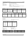
Verification test - tables of limits
20 V DC basic voltage range with linearity testing
Function
Range
V-DC
V-DC
V-DC
V-DC
V-DC
V-DC
V-DC
V-DC
V-DC
V-DC
Table I
10.0
10.0
10.0
10.0
10.0
10.0
10.0
10.0
10.0
10.0
Value (V)
V
V
V
V
V
V
V
V
V
V
Frequency
(Hz)
Max.
deviation
(% of value)
0.008
0.006
0.005
0.004
0.004
0.008
0.006
0.005
0.004
0.004
Frequency
(Hz)
Max.
deviation
(% of value)
0.004
0.004
0.004
0.004
0.004
0.004
0.004
0.004
0.004
0.004
0.004
0.004
0.004
0.003
0.004
0.003
0.010
0.010
2.0
4.0
6.0
8.0
10.0
-2.0
-4.0
-6.0
-8.0
-10.0
DC voltage ranges
Function
Range
V-DC
V-DC
V-DC
V-DC
V-DC
V-DC
V-DC
V-DC
V-DC
V-DC
V-DC
V-DC
V-DC
V-DC
V-DC
V-DC
V-DC
V-DC
Table II
10
10
10
10
100
100
100
100
1.0
1.0
1.0
1.0
100.0
100.0
100.0
100.0
750.0
750.0
Operation manual v22
Value (V)
mV
mV
mV
mV
mV
mV
mV
mV
V
V
V
V
V
V
V
V
V
V
5 m
9 m
-5 m
-9 m
50 m
90 m
-50 m
-90 m
-0.5
1.0
-0.5
-1.0
50.0
100.0
-50.0
-100.0
300.0
700.0
39
Powertek
Portable Multifunction CalibratorMC-141
20 V AC voltage basic range with linearity testing
Function
Range
V-AC
V-AC
V-AC
V-AC
V-AC
Table III
10.0
10.0
10.0
10.0
10.0
Value (V)
V
V
V
V
V
2.0
4.0
6.0
8.0
10.0
Frequency
(Hz)
100
100
100
100
100
Max.
deviation
(% of value)
0.075
0.050
0.042
0.037
0.035
AC voltage ranges
Function
Range
Value (V)
V-AC
V-AC
V-AC
V-AC
V-AC
V-AC
V-AC
Table IV
10 mV
100 mV
1.0 V
10.0 V
10.0 V
100.0 V
750.0 V
0.010
0.100
1.0
10.0
10.0
100.0
750.0
Frequency
(Hz)
1000
1000
1000
50
300
1000
1000
Max.
deviation
(% of value)
0.358
0.142
0.030
0.030
0.030
0.030
0.036
200 mA DC current basic range with linearity testing
Function
Range
A-DC
A-DC
A-DC
A-DC
A-DC
A-DC
A-DC
A-DC
A-DC
A-DC
Table V
200.0
200.0
200.0
200.0
200.0
200.0
200.0
200.0
200.0
200.0
Value (A)
mA
mA
mA
mA
mA
mA
mA
mA
mA
mA
Frequency
(Hz)
Max.
deviation
(% of value)
0.025
0.018
0.015
0.014
0.013
0.025
0.018
0.015
0.014
0.013
Frequency
(Hz)
Max.
deviation
(% of value)
0.061
0.061
0.025
0.025
0.013
0.013
0.04
0.08
0.12
0.16
0.18
-0.04
-0.08
-0.12
-0.16
-0.18
DC current ranges
Function
Range
A-DC
A-DC
A-DC
A-DC
A-DC
A-DC
Table VI
200.0
200.0
2.0
2.0
20.0
20.0
40
Value (A)
uA
uA
mA
mA
mA
mA
0.00018
-0.00018
0.0018
-0.0018
0.018
-0.018
Operation manual v22
Portable Multifunction CalibratorMC141
Powertek
AC current ranges
Function
Range
A-AC
A-AC
A-AC
A-AC
A-AC
A-AC
A-AC
A-AC
Table VII
200.0
2.0
20.0
20.0
20.0
20.0
200.0
2.0
Value (A)
uA
mA
mA
mA
mA
mA
mA
A
Frequency
(Hz)
0.00018
0.0018
0.018
0.018
0.018
0.018
0.18
1.8
100
100
100
300
100
100
100
100
Max.
deviation
(% of value)
0.161
0.081
0.055
0.055
0.055
0.055
0.055
0.055
Resistance
Function
Range
O-4W
O-4W
O-4W
O-4W
O-4W
O-4W
O-4W
O-4W
O-4W
Table VIII
10.0
100.0
100.0
1000
10k
100k
1M
10M
100M
Value (Ohm)
Ohm
Ohm
Ohm
Ohm
Ohm
Ohm
Ohm
Ohm
Ohm
10.0
10.0
100.0
1000.0
10000.0000
100000.0000
1.000000e+6
1.000000e+7
1.000000e+8
Frequency
(Hz)
DC
DC
DC
DC
DC
DC
DC
DC
DC
Max.
deviation
(% of value)
0.130
0.130
0.015
0.015
0.015
0.015
0.050
0.200
0.500
Frequency
Function
Range
FREQ
Table IX
Operation manual v22
1 MHz
Value (Hz)
1 000 000
Frequency
(Hz)
Max.
deviation
(% of value)
0.005
41
Powertek
Portable Multifunction CalibratorMC-141
Interface
The calibrator is equipped with RS232 serial line as standard (standardized IEEE-488 bus as option). System
connectors are located at the rear panel. For the remote control to work properly, interface parameters must
be set in the system menu. For RS232 line communication speed can be set (150 to 19200 Bd), software
handshake XON/XOFF. For IEEE-488 bus, an address from range 0 to 30 is allowed. The calibrator can be
only controlled by one of interfaces at a time. It is therefore necessary to select one of the interfaces
(GPIB/RS232) using the system menu.
IEEE-488 bus properties
The instrument performs the following functions based on GPIB bus commands:
SH1, AH1, T5, L3, RL1, DC1, SR1
The instrument also recognizes the following general commands:
DCL
SDC
EOI
GTL
LLO
SPD
SPE
Device Clear
Selected Device Clear
End or Identify Message Terminator
Go To Local
Local Lock Out
Serial Poll Disable
Serial Poll Enable
reset the calibrator
reset the calibrator
close the message
close remote control mode
local control locked
close serial message status
release serial message status
RS232 serial line setting
To transfer the data using RS232 bus, 8N1 data format is used, i.e. each data word includes 8 bits, no parity
and one stop bit. The communication speed can be set using the system menu. Available values: 150, 300,
600, 1200, 2400, 4800, 9600 and 19200 Bd. Software handshake (communication control) XON/XOFF can
be set to control the transfer of the data through the bus.
RS-232 connector layout
Pin
Name
Direction
Description
2
3
5
TXD
RXD
GND
Output
Input
-
Transmitter
Receiver
Ground
9-pin connector D-SUB FEMALE
42
Operation manual v22
Portable Multifunction CalibratorMC141
Cable between the calibrator and PC (configuration 1:1)
PC
D-Sub 1 D-Sub 2
Receiver
2
2
Transmitter
Transmitter
3
3
Receiver
Ground
5
5
Ground
Powertek
MC-141
Command syntax
The commands described in this chapter can be issued through both buses (IEEE-488 and RS232).
All commands listed in this chapter are explained in two columns:
KEYWORD and PARAMETERS.
KEYWORD column includes the name of the command. Each command includes one or more keywords. If
a keyword is in brackets ( [ ] ), it is not mandatory. Non-mandatory commands are used only to achieve
compatibility with language standard SCPI.
Capitals designate the abbreviated form of the commands; extended form is written in lowercase.
Command parameters are in brackets (<>); each parameter is separated using a comma. Parameters in
brackets ( [ ] ) are not mandatory. Line ( | ) means “or” and is used to separate several alternative
parameters.
Semicolon ‘;’ is used to separate more commands written on one line.
E.g. VOLT 2.5 ; OUTP ON
Note:
Each command must end in <cr> or <lf>. Both codes <crlf> can be used at the same time. The calibrator
performs all commands written on one line of the program after it receives <cr>, <lf> or <crlf> code.
Without this code, the program line is ignored.
Description of abbreviations
<DNPD> = Decimal Numeric Program Data, this format is used to express decimal number with or without
the exponent.
<CPD> =
Character Program Data. Usually, it represents a group of alternative character parameters. E.g.
{ON | OFF | 0 | 1}.
<SPD> =
String Program Data. String value consisting from more parts. It is used for date/time setting.
?=
A flag indicating a request for the value of the parameter specified by the command. No other
parameter than the question mark can be used.
(?) =
A flag indicating a request for the parameter specified by the command. This command permits
a value to be set as well as requested.
<cr> =
carriage return. ASCII code 13. This code executes the program line.
<lf> =
line feed. ASCII code 10. This code executes the program line.
Operation manual v22
43
Powertek
Portable Multifunction CalibratorMC-141
OUTPut subsystém
This subsystem enables to activate or deactivate the M141output and switch on/off current coil function.
Keyword
Parameters
OUTPut
[:STATe](?)
: ISELection(?)
<CPD> { ON | OFF | 0 | 1 }
<CPD> { HIGHi | HI50turn }
OUTP [:STAT](?) <CPD> { ON | OFF | 0 | 1 }
This command activates or deactivates output terminals.
• ON or 1 - activates the output
• OFF or 0 - deactivates the output
If query is sent, M141 returns ON if the output is active or OFF if it is inactive
Example:
OUTP 1 <cr> - activates the output
OUTP ? <cr> - the calibrator returns ON or OFF
OUTP :ISEL(?) <CPD> { HIGH | HI50 }
This command activates or deactivates the 100A current range (using a 50-turn coil).
• HIGH - deactivates the 50-turn coil
• HI50 - activates the 50-turn coil (up to 100A range)
If query is sent, M141 returns HIGH if the 50-turn coil is deactivated or HI50 if it is activated.
Example:
OUTP :ISEL HI50 <lf> activates the 50-turn coil
OUTP :ISEL ? <lf> the calibrator returns HIGH or HI50
SOURce subsystem
This subsystem allows to control the individual functions of M141 calibrator.
Keyword
[SOURce]
:FUNCtion
[:SHAPe](?)
Parameters
<CPD> { DC | SINusoid | RMPA | RMPB | TRIangle |
LIMS | SQUare }
:VOLTage
[:LEVEl]
[:IMMediate]
[:AMPLitude](?)
<DNPD
:CURRent
[:LEVEl]
[:IMMediate]
[:AMPLitude](?)
<DNPD>
>
:RESistance
[:LEVEl]
44
Operation manual v22
Portable Multifunction CalibratorMC141
[:IMMediate]
[:AMPLitude](?)
Powertek
<DNPD>
:EARTh(?)
<CPD> { ON | OFF | 0 | 1 }
:FREQuency
[:CW ](?)
<DNPD>
:TEMPerature
:UNITs(?)
:SCALe(?)
:THERmocouple
[:LEVEl]
[:IMMediate]
[:AMPLitude](?)
:TYPE(?)
:RJUN
:RSELect(?)
:SIMulated(?)
: PRT
[: LEVEl]
[: IMMediate]
[: AMPLitude] (?)
: TYPE (?)
: NRESistance (?)
[SOUR] :FUNC [:SHAP](?) <CPD> {
<CPD> { C | CEL | F | FAR }
<CPD> { TS68 | TS90 }
<DNPD>
<CPD> { B | E | J | K | N | R | S | T }
<CPD> { REAL | SIMulated }
<DNPD>
<DNPD>
<CPD> { PT385 | PT392 | NI }
<DNPD>
DC | SIN | RMPA | RMPB | TRI | LIMS | SQU }
This command sets the shape of the output signal. At the same time, the respective function must be set. E.g.
for :VOLT or :CURR function, FUNC DC, FUNC SIN, or other signal shape must be set. Some functions
(:RES) do not require any other settings.
•
•
•
DC sets a DC output signal for voltage, current or power modes.
SINusoid sets AC output signal for voltage, current or power modes.
RMPA sets AC output signal - ramp shape A- for voltage or current modes. The amplitude can be set. The output switches between -amplitude a +amplitude.
• RMPB sets AC output signal - ramp shape B - for voltage or current modes. The amplitude can be set. The output switches between -amplitude a +amplitude.
• TRIangel sets AC output signal - triangular shape - for voltage or current modes. The amplitude can be
set. -The output switches between -amplitude a +amplitude.
• LIMSinusoid sets AC output signal - sinus shape with limitation of amplitude- for voltage or current
modes. The amplitude can be set. -The output switches between -amplitude a +amplitude.
• SQUare sets digital frequency output.
If query is sent, M141 returns a string containing { DC | SIN | RMPA | RMPB | TRI | LIMS | SQU }
depending on the current setting. If resistance or temperature sensor simulation is set, NONE is returned.
[SOUR] :VOLT [:LEVE] [:IMM] [:AMPL] (?) <DNPD>
This command activates the generation of DC or AC voltage (depending on the DC or SIN parameter of the
FUNC command).
Operation manual v22
45
Powertek
Portable Multifunction CalibratorMC-141
<DNPD>
The command represents the value of DC or AC voltage expressed in Volts. Negative value is accepted for
DC voltage. “Technical Data” chapter lists the acceptable ranges.
If query is sent, M141 returns the set value of current using standard exponential format. Example:
20.547mV is returned as -2.054700e-002. Positive numbers are sent without “+” sign.
Examples:
DC voltage 5V:
FUNC DC;:VOLT 5<lf>
AC voltage 5V, 100Hz:
FUNC SIN;:VOLT 5;:FREQ 100<lf>
[SOUR] :CURR [:LEVE] [:IMM] [:AMPL] (?) <DNPD>
This command activates the generation of DC or AC current (depending on the DC or SIN parameter of the
FUNC command).
<DNPD>
The command represents the value of DC or AC current expressed in Amperes. Negative value is accepted
for DC current. “Technical Data” chapter lists the acceptable ranges.
If query is sent, M141 returns the set value of current using standard exponential format. Example:
20.547mA is returned as -2.054700e-002. Positive numbers are not preceded with “+” sign.
Examples::
DC current 18mA:
FUNC DC;:CURR 0.018<lf>
AC current 18mA, 100Hz:
FUNC SIN;:CURR 0.018;:FREQ 100<lf>
[SOUR] :RES [:LEVE] [:IMM] [:AMPL] (?) <DNPD>
This command activates the generation of a resistance.
<DNPD>
The command represents the value of the resistance in Ohms. “Technical Data” chapter lists the acceptable
ranges.
If query is sent, M141 returns the calibration value of resistance using standard exponential format.
Example: 100.5Ω is returned as 1.005000e+002.
Example :
Resistance 1kΩ setting:
RES 1000<lf>
[SOUR] :EART(?) <CPD> { ON | OFF | 0 | 1 }
This command connects or disconnects the voltage Lo terminal to/from GND terminal.
• ON or 1 grounds the voltage output
• OFF or 0 ungrounds the voltage output
If query is sent, M141 returns ON when the output is grounded or OFF when ungrounded.
Example:
46
Operation manual v22
Portable Multifunction CalibratorMC141
Powertek
Grounding of the voltage output terminal Lo
EART : VOLT 1 <lf>
[SOUR] :FREQ [:CW] (?) <DNPD>
This command sets the frequency being generated.
Examples:
AC voltage frequency :
FUNC :SIN ; :VOLT <DNPD>; :FREQ <DNPD> <lf>
AC current frequency :
FUNC :SIN ; :CURR <DNPD>; :FREQ <DNPD> <lf>
Digital frequency :
FUNC :SQU ; :FREQ <DNPD> <lf>
<DNPD>
It represents the frequency in Hz. . “Technical Data” chapter lists the acceptable ranges which depend on the
selected function mode.
If query is sent, M141 returns the set value of the current using standard exponential format. Example:
200.5Hz is returned as 2.005000e+002.
[SOUR] :TEMP :UNIT(?) <CPD> { C | CEL | F | FAR }
This command sets the unit of measurement of temperature.
•
•
C or CEL sets „Centigrade“
F or FAR sets „Kelvin“
The unit of measurement remains valid after the calibrator is switched off.
If query is sent, M141 returns the set unit of measurement{ C | K }.
[SOUR] :TEMP :SCAL (?) <CPD> { TS68 | TS90 }
This command sets one of temperature scales. The setting influences the simulation of resistance
temperature sensors and thermocouples.
•
•
TS68 sets IPTS-68 temperature scale
TS90 sets ITS-90 temperature scale
The temperature scale remains valid after the calibrator is switched off.
If query is sent, M141 returns the set temperature scale { TS68 | TS90 }.
[SOUR] :TEMP :THER :TYPE (?) <CPD> { B | E | J | K | N | R | S | T }
This command sets the type of thermocouple to be simulated.
If query is sent, M141 returns the set type thermocouple { B | E | J | K | N | R | S | T }.
Operation manual v22
47
Powertek
Portable Multifunction CalibratorMC-141
Examples:
TC type K setting, temperature 200°C, ITS-90 temperature scale:
:TEMP:UNIT C;:TEMP:SCAL TS90;:TEMP:THER:TYPE K;:TEMP:THER 200 <lf>
[SOUR] :TEMP :THER :RJUN :RSEL(?) <CPD> { REAL | SIM }
This command sets type of getting the cold end of thermocouple RJ temperature. The RJ temperature can be
either measured by internal thermometer or simulated.
•
•
REAL sets measured RJ temperature
SIM sets simulated RJ temperature
If query is sent, M141 returns the set type of RJ temperature { REAL | SIM }.
[SOUR] :TEMP :THER :RJUN :SIM(?) <DNPD>
This command sets the temperature of cold end of thermocouple RJ.
<DNPD>
Represents the temperature expressed in the units set by the ‘UNIT’ command. “Technical Data” chapter
lists the acceptable ranges.
Example: to set the temperature of cold end of thermocouple to 25°C:
:TEMP :THER :RJUN :SIM 25 <lf>
If query is sent, M141 returns the set temperature using standard exponential format. Example: 20.5°C is
returned as 2.050000e+001.
[SOUR] :TEMP :PRT [:LEVE] [:IMM] [:AMPL] (?) <DNPD>
This command activates the simulation of resistance temperature sensors (resistance generation).
<DNPD>
Represents the temperature expressed in the units set by the ‘UNIT’ command. “Technical Data” chapter
lists the acceptable ranges.
If query is sent, M140 returns the set temperature using standard exponential format. Example: 20.5°C is
returned as 2.050000e+001.
[SOUR] :TEMP :PRT :TYPE (?) <CPD> { PT385 | PT392 | NI }
This command sets the type of resistance temperature sensor to be simulated.
Example: to activate the simulation of platinum resistance temperature sensor at 350°C approximated using
PT385 table (Europe):
:TEMP :PRT 350; :TEMP :PRT :TYPE PT385 <cr>
If query is sent, M141 returns the set type of approximation table { PT385 | PT392 | NI }.
[SOUR] :TEMP :PRT :NRESistance (?) <DNPD>
This command sets the nominal resistance of the resistance temperature sensor at 0°C. 100Ω to 1kΩ can be
set.
48
Operation manual v22
Portable Multifunction CalibratorMC141
Powertek
<DNPD>
Represents the nominal resistance in Ohms.
If query is sent, M141 returns the set value of nominal resistance using standard exponential format.
Example: 100Ω is returned as 1.000000e+002.
SYSTem subsystem
The subsystem enables to control various functions from the MENU.
SYSTem
:DATE(?)
:TIME(?)
<DNPD>,<DNPD>,<DNPD>
<DNPD>,<DNPD>,<DNPD>
SYST :DATE(?) <DNPD>,<DNPD>,<DNPD>
This command sets system date of the calibrator.
<DNPD>,<DNPD>,<DNPD>
Represents date in format YYYY, MM, DD.
If query is sent, M141 returns current value of system date in format YYYY,MM,DD.
where YYYY = year (2000..2099)
MM = month (01..12)
DD = day (01..31)
SYST :TIME(?) <DNPD>,<DNPD>,<DNPD>
This command sets time of the calibrator.
<DNPD>,<DNPD>,<DNPD>
Represents time in format HH,MM,SS.
If query is sent, M141 returns current value of system time in format HH,MM,SS.
where HH = hour (00..23)
MM = minute (00..59)
SS = second (00..59)
I/D (instrument identification)
*IDN?
This command returns the identification of the manufacturer, model, serial number and firmware revision.
The reply is formatted as follows:
Powertek,MC-141,412341,4.6
Operation complete
*OPC
Operation manual v22
49
Powertek
Portable Multifunction CalibratorMC-141
This command sets the OPC bit in the ESR (Event Status Register) when all pending operations are
complete.
Operation complete?
*OPC?
This command returns “1” to the output queue after all pending operations are complete.
Wait-to-Continue command
*WAI
Prevents the instrument from executing any further commands or queries until all previous remote
commands have been executed.
Reset
*RST
This command resets the calibrator to its initial status.
Test operation
*TST?
This command launches an internal self-test. Return the self-test result (“0” for pass or “1” for fail).
Status byte reading (IEEE488 only)
*STB?
This query returns number in range 0 to 255 with information about content of register STB, which carries
the MSS bit status.
Service Request Enable reading (IEEE488 only)
*SRE <value>
This command sets condition of the Service Request Enable register. Since bit 6 is not used, the maximum
value is 191.
Service Request Enable reading (IEEE488 only)
*SRE?
This query returns the Service Request Enable Register number.
Event Status Register reading (IEEE488 only)
50
Operation manual v22
Portable Multifunction CalibratorMC141
Powertek
*ESR?
This query returns the contents of the Event Status Register and clears the register.
Event Status Enable setting (IEEE488 only)
*ESE <value>
This command programs the Event Status Enable register bits. Parameter “value” is number in range 0 –
255.
Event Status Enable reading (IEEE488 only)
*ESE?
This query returns the Event Status Enable register.
Clear status (IEEE488 only)
*CLS
This command clears the Event Status Register and the Status Byte Register except the MAV bit and output
queue. Output line is not reset.
Remote control
*REM
This command activates the remote control. When the calibrator is controlled by GPIB bus, it goes to the
remote control mode automatically. When remote control is active, the calibrator ignores all controls from
the front panel, except LOCAL button.
Local control
*LOC
This command activates the local control (using front panel buttons). When the calibrator is controlled by
GPIB bus, it goes to the local control mode automatically.
Local control lock
*LLO
This command locks out the local control; the calibrator cannot be returned to local control by pressing
LOCAL button. Return to local control can only be performed by a command sent through the bus, or by
switching the calibrator off and on.
Local control unlock
*UNL
Operation manual v22
51
Powertek
Portable Multifunction CalibratorMC-141
This command cancels the „*LLO“ command. Unlocked calibrator can be returned to local control mode by
pressing LOCAL button.
Standard Status Data Structures
Calibrator meets standard protocol according to the standard IEEE488.2. The protocol can be used for
checking of error and status behavior of the calibrator. It enables single-wire transmitting of SRQ command.
The conditions on which SRQ signal (local control request) is sent can be set with parameters *STB?,
*SRE?, *SRE, *ESR?, *ESE?, *ESE a *CLS.
Status data structure of M140 Calibrator contains following registers:
STB – Status Byte Register
SRE – Service Request Enable Register
ESR – Event Status Register
ESE – Event Status Enable Register
Output Queue
52
Operation manual v22
Portable Multifunction CalibratorMC141
Powertek
STB Status Byte Register
STB is main register where information from other status registers and from output queue is collected.
Value of STB register is reset after switching on the calibrator or after sending command *CLS. This
command reset the STB register except bit MAV, which remains set if the output queue is not empty. STB
register value can be read via serial message or through general query *STB? .
Bit configuration of Status Byte Register :
RQS
Request Service, bit 6. The bit is read as a part of status byte only when serial message is sent.
MSS
Master Summary Status, bit 6. The MSS bit is set to 1 whenever bits ESB or MAV are 1 and
enabled (1) in the SRE. This bit can be read using the *STB? command. His value is derived from
STB and SRE status.
ESB
Event Summary Bit, bit 5. His value is derived from STB and SRE status. The ESB bit is set to 1
when one or more enabled ESR bits are set to 1.
MAV Message Available, bit 4. The MAV bit is set to 1 whenever data is available in the M141 IEEE488
Output Queue (the response on query is ready).
SRE Service Request Enable Register
The Service Request Enable Register suppresses or allows the STB bits. “0” value of a SRE bit means, that
the bit does not influence value of MSS bit. Value of any unmask STB bit results in setting of the MSS bit
to the level “1” . SRE bit 6 is not influenced and its value is “0”. The SRE register value can be set via the
command *SRE followed by mask register value (0 – 191). The register can be read with the command
*SRE?. The register is automatically resets after switching the calibrator on. The register is not reset by the
command *CLS.
ESR Event Status Register
Every bit of the EventStatusRegister corresponds to one event. Bit is set when the event is changed and it
remains set also when the event passed. The ESR is cleared when the power is turned on (except bit PON
which is set), and every time it is read via command *ESR? Or cleared with *CLS.
Bit configuration of Event Status Register :
PON
Power On, bit 7. This event bit indicates that an off-to-on transition has occurred in the device’s
power supply.
URQ
User Request, bit 6. Bit is not used and it is always “0”.
CME
Command Error, bit 5. This event bit indicates that an incorrectly formed command or query has
been detected by the M141.
EXE
Execution Error, bit 4. This event bit indicates that the received command cannot be executed,
owing to the device state or the command parameter being out of limits.
DDE
Device Dependent Error, bit 3. This event bit indicates that an error has occurred which is neither a
Command Error, a Query Error, nor an Execution Error. A Device-specific Error is any executed
device operation that did not properly complete due to some condition, such as overload.
QYE
Query Error, bit 2. The bit is set if the calibrator is addressed as talker and output queue is empty or
if control unit did not pick up response before sending next query.
Operation manual v22
53
Powertek
OPC
Portable Multifunction CalibratorMC-1411
Operation Complete, bit 0. This event bit is generated in response to the *OPC command. It
indicates that the device has completed all selected pending operations.
ESE Event Status Enable Register
The Event Status Enable Register allows one or more events in the Event Status Register to be reflected in
the ESB summary-message bit. This register is defined for 8 bits, each corresponding to the bits in the Event
Status Register. The Event Status Enable Register is read with the common query *ESE?. Data is returned as
a binary-weighted value. The Event Status Enable Register is written to by the common command, *ESE.
Sending the *ESE common command followed by a zero clears the ESE. The Event Status Enable Register
is cleared upon power-on.
It suppresses or allows bits in ESR register. Value „0“ of a bit of ESE register suppresses influence of
appropriate bit of ESR register on value of sum bit of ESB status register. Setting of any unmask bit of ESR
register results in setting of ESB status register. ESE register value can be modified by command *ESE
followed by value of mask register (integer in range 0 –255). Reading of the register can be performed with
command *ESE?. The register is automatically reset after switching on. The register is not reset with *CLS
command.
Output Queue
The Output Queue stores response messages until they are read from control unit. If there is at minimum one
sign in the output queue, MAV register (message available) is set. The Output Queue is cleared upon poweron and after reading all signs from output queue.
54
Operation manual v22
Powertek
Portable Multifunction CalibratorMC-141
Specification
Bellow shown uncertainties are valid after specified warm-up time in temperature range 23 ± 2 oC. The
uncertainties include long-term stability, temperature coefficient, linearity, load and line regulation and the
traceability of factory and National calibration standards. Specified uncertainties are valid for one year after
the last calibration. Specified uncertainties „of range“ are related to the maximal value which cam be set on
the range. All uncertainties are calculated for coefficient probability 95% in normal distribution.
Technical data
Voltage
Voltage range totally :
Ranges :
Frequency range :
Frequency resolution :
Accuracy of frequency :
Output waveform :
0 µV – 750 V DC, 1 mV – 750 V AC
100 mV, 1 V, 10 V, 100 V, 750 V
1 mV - 10 V 20 Hz to 2 kHz,
10 V – 100 V 40 Hz to 2 kHz
100 V – 750 V 40 Hz to 1 kHz
0.001 Hz to 1 kHz
0.01 Hz to 2 kHz
0.01%
harmonic :
sinus
non-harmonic : triangle symmetrical, triangle A/ B , square, limited sin
(with defined distortion k=13.45%) from 1 mV to 10 V,
frequency range 20 to 80 Hz
AC voltage
DC voltage
Range
% of value + % of range
0.0000 µV – 10.0000 mV
0.05 + 0.005 + 10 µV
10.000 mV – 100.000 mV
0.01 + 0.001 + 10 µV
0.10000 mV – 1.00000 V
0.008 + 0.002
1.0000 V – 10.0000 V
0.008 + 0.002
10.000 V – 100.000 V
0.015 + 0.004
100.00 V – 750.00 V
0.018 + 0.004
Range
% of value + % of range
% of value + % of range
20 Hz - 200 Hz
200 Hz -2000 Hz
1.0000 mV – 10.0000 mV
0.20 + 0.05 + 20 µV
0.20 + 0.10 + 20 µV
10.000 mV – 100.000 mV
0.10 + 0.03 + 20 µV
0.15 + 0.05 + 20 µV
0.10000 mV – 1.00000 V
0.05 + 0.005
0.07 + 0.01
1.0000 V – 10.0000 V
0.05 + 0.005
0.07 + 0.03
0.05 + 0.010
0.07 + 0.03
10.000 V – 100.000 V
*1
*2
*1
Hz
100.00 V – 750.00 V
0.07 + 0.02
0.1 + 0.03
*2
Voltage range 100 V from 40 Hz to 1000 Hz
Voltage range 750 V from 40 Hz to 1000
Auxiliary parameters
Range
*3
58
100mV
1V
10V
100V
750V
0.05 % + 200 µV
0.05 % + 300 µV
0.05 %
0.05 %
0.05 %
0.2 %
5 mA
5 mA
10 mA
30 mA
10 mA
2 mA
Output impedance
< 10 mΩ
< 10 mΩ
< 10 mΩ
< 10 mΩ
< 100 mΩ
< 100 mΩ
Maximum capacitance load
500 pF
500 pF
500 pF
500 pF
300 pF
150 pF
0.3 %
0.3 %
--
--
THD*3
Maximum output current
10mV
Amplitude accuracy in non0.3 % + 50 uV
0.3 % + 50 uV
harmonic mode (peak value)
Parameter includes harmonic distortion and non-harmonic noise in range to 1 MHz
Current
Operation manual v22
Portable Multifunction CalibratorMC141
Powertek
0 µA – 2 A DC, 1 µA – 2 A AC
200 µA, 2 mA, 20 mA, 200 mA, 2A
20 Hz to 1 kHz, accuracy of frequency 0.01%
0.001 Hz
harmonic :
sinus
non-harmonic : triangle symmetric, triangle A/ B , square, limited sinus
from 100 uA to 2 A, frequency range 20 to 80 Hz
Current range totally :
Ranges :
Frequency range :
Frequency resolution :
Output wave form :
AC current
DC current
Range
% of value + % of range
Range
% of value+% of range
% of value+% of range
20 Hz – 200 Hz
200 Hz – 1000 Hz
0.25 + 0.0 + 20 nA
0.30 + 0.10 + 20 nA
0.000 µA – 200.000 µA
0.05 + 0.0 + 20 nA
0.20000 mA – 2.00000 mA
0.025 + 0.005
1.000 µA – 200.000 µA
2.0000 mA – 22.0000 mA
0.015 + 0.003
0.20000 mA – 2.00000 mA
0.10 + 0.01
0.20 + 0.05
22.000 mA – 200.000 mA
0.015 + 0.003
2.0000 mA – 22.0000 mA
0.07 + 0.005
0.20 + 0.05
0.20000 mA – 2 0000A
0.015 + 0.005
22.000 mA – 200.000 mA
0.07 + 0.005
0.20 + 0.05
0.20000 mA – 2 0000A
0.1 + 0.005
0.25 + 0.05
Auxiliary parameters
*4
Range
200 µA
2 mA
20 mA
200 mA
2A
Maximum inductive load
400 µH
400 µH
400 µH
400 µH
200 µH
Maximum voltage on the load
(pk)
2V
2V
2 VAC, 7 VDC
2V
2V
THD*4
0.2 %
0.2 %
0.2 %
0.2 %
0.2 %
0.3 %
0.3 %
0.3 %
Amplitude accuracy in non0.3 % + 1 uA
0.3 % + 1 uA
harmonic mode (peak value)
Parameter includes harmonic distortion and non-harmonic noise in range to 1 MHz
Resistance
Range totally :
Maximum voltage/dissipation power :
Range
10 Ω to 100 MΩ in fix decade values
50 Vef / 0.1 W
Calibration uncertainty[%]
Tolerance [%]
10.0000 Ω
0.03 + 10 mΩ
0.2 + 100mΩ
100.000 Ω
0.05
0.2 + 100mΩ
1.00000 kΩ
0.02
0.2
10.0000 kΩ
0.02
0.2
100.000 kΩ
0.02
0.2
1.00000 MΩ
0.05
0.2
10.0000 MΩ
0.05
1
100.000 MΩ
0.5
2
RTD temperature sensor simulation (option)
Type :
Temperature scale :
Temperature standard:
Accuracy
Temperature range
Pt100-Pt200
Pt 100-1000, Ni 100-1000
ITS90, IPTS68
IEC (1.385), US (1.391)
Pt201-Pt1000
Temperature range
Ni100-Ni200
Ni201-Ni1000
-200.0 … 0.0 °C
0.2 °C
0.2 °C
-60.0 … 0.0 °C
0.2 °C
0.1 °C
0.1 … 850.0 °C
0.2 °C
0.2 °C
0.1 … 300.0 °C
0.1 °C
0.1 °C
Operation manual
59
Portable Multifunction CalibratorMC141
Powertek
Ranges and accuracy of the thermocouple sensor simulation
Type :
Temperature scale :
R, S, B, J, T, E, K, N
ITS90, IPTS68
R
range [oC]
accuracy [oC]
-50.0 – -0.1
2.5
0.0 – 399.9
2.0
400.0 – 999.9
1.2
1000.0 – 1767.0
1.2
S
range [oC]
accuracy [oC]
-50.0 – -0.1
2.2
0.0 – 249.9
2.1
250.0 – 1399.9
1.5
1400.0 – 1767.0
1.5
B
range [oC]
accuracy [oC]
400.0 – 799.9
2.7
800.0 – 999.9
1.5
1000.0 – 1499.9
1.4
1500.0 – 1820.0
1.3
J
range [oC]
accuracy [oC]
-210.0 – -100.1
0.9
-100.0 – 149.9
0.4
150.0 – 699.9
0.3
700.0 – 1200.0
0.4
T
range [oC]
accuracy [oC]
-200.0 – -100.1
0.9
-100.0 - -0.1
0.5
0.0 – 99.9
0.3
100.0 – 400.0
0.3
E
range [oC]
accuracy [oC]
-250.0 - -100.1
1.7
-100.0 – 279.9
0.3
280.0 – 599.9
0.2
600.0 – 1000.0
0.3
K
range [oC]
accuracy [oC]
-200.0 - -100.1
0.8
-100.0 – 479.9
0.4
480.0 – 999.9
0.4
1000.0 – 1372.0
0.5
N
range [oC]
accuracy [oC]
-200.0 - -100.1
1.3
-100.0 – -0.1
0.6
0.0 – 579.9
0.6
580.0 – 1300.0
0.5
Uncertainties in the table are maximal uncertainties of TC sensor simulation. Actual uncertainty for each
set value of simulated temperature is determined by uncertainty of relevant resistance. Actual
temperature uncertainty is displayed on the calibrator display. Actual uncertainties are always lower than
those in above table.
When automatic compensation of cold junction temperature via external Pt1000 sensor is used, summary
uncertainty of simulated temperature is higher due to limited accuracy of measuring ambient temperature
with the external sensor. This additional uncertainty is 0.2 oC in temperature range from 15 to 35 oC.
Frequency
Waveform :
Frequency range :
Frequency resolution :
Uncertainty:
square with fix amplitude 5Vpk-pk / 50 Ohm
0.1 Hz to 2 MHz
5 ½ digit
0.005%
General data
Reference temperature range :
Warm-up time :
Working temperatures :
Temperature coefficient
Storing temperatures :
Pressure :
Power supply voltage :
Power consumption :
Dimensions :
60
23 °C ± 2 °C (for specified uncertainties)
In temperature range 23 °C ± 5 ° uncertainties are 2 x higher
5 min
+5 °C … +40 °C
Temperature coefficient for temperature outside of Tcal ±2
°C between +5 °C to +40 °C is 0.15 x /°C
-10 to 55 °C at relative humidity to 80 %
86000 to 106000 Pa
115/230V - 50/60 Hz
40 VA max
325mm x 111mm x 316mm
Operation manual v22