1
BuildSoft n.v.
User’s manual ConCrete
User’s manual
ConCrete
1
BuildSoft n.v.
User’s manual ConCrete
© BuildSoft NV
All rights reserved. No part of this document may be reproduced or
transmitted in any form or by any means, electronic or manual, for any
purpose whatsoever, without the prior written consent from BuildSoft.
The programs described in this manual are subject to copyright by
BuildSoft. They may only be used by the licensee and may only be
copied for the purpose of creating a security copy. It is prohibited by law
to copy them for any other purpose than the licensee’s own use.
Although BuildSoft has tested the programs described in this manual and
has reviewed this manual, they are delivered ‘As Is’, without any
warranty as to their quality, performance, merchantability or fitness for
any particular purpose. The entire risk as to the results and performance
of the programs, and as to the information contained in the manual, lies
with the end-user.
2
BuildSoft n.v.
User’s manual ConCrete
CONTENT
CONTENT............................................................................................... 3
CHAPTER 1 INTRODUCTION.............................................................. 6
1.1. Hard- & software requirements ............................................................. 7
1.2. Installing ConCrete ................................................................................. 7
1.3. ConCrete, ConCrete Plus and ConCrete List....................................... 7
CHAPTER 2 A SIMPLE BEAM............................................................. 8
2.1. Introduction ............................................................................................. 9
2.2. Creating a new project ........................................................................... 9
2.3. Entering a new element ....................................................................... 10
2.4. Interpretation of the calculated results .............................................. 12
2.4.1. The "Structure and loads”-window ..................................................... 13
2.4.2. The "Diagrams”-window ..................................................................... 14
2.4.3. The "Reinforcement sketch”-window.................................................. 15
2.5. Modifying entered data ........................................................................ 16
2.5.1. Direct editing of entered data ............................................................. 16
2.5.2. Modifying with the right mouse button................................................ 19
CHAPTER 3 A SECOND BEAM ......................................................... 21
3.1. A beam in the Projectlist-window ....................................................... 22
3.2. Concentrated & trapezoidal forces ..................................................... 22
3.2.1. Trapezoidal forces .............................................................................. 23
3.2.2. Concentrated forces ........................................................................... 24
3.2.3. Modifying the amount of zones .......................................................... 25
3.2.3.1. Modifying directly .............................................................................................25
3.2.3.2. Modification by using the right mouse button ...................................................27
3.3. Adding concentrated moments ........................................................... 28
3.4. A beam with a variable section ........................................................... 29
CHAPTER 4 CALCULATION PARAMETERS ................................... 34
4.1. Project values ....................................................................................... 35
4.2. Parameters for reinforcement steel .................................................... 36
4.3. Parameters for concrete ...................................................................... 38
4.4. Parameters for the supports ............................................................... 40
4.5. Parameters for the redistribution of moments .................................. 41
4.6. Parameters for the loads ..................................................................... 43
3
BuildSoft n.v.
User’s manual ConCrete
CHAPTER 5 MORE THAN ONE LOAD TYPE ................................... 47
5.1. Introduction ........................................................................................... 48
5.2. A beam with two load types ................................................................ 48
5.3. Adding and removing load types ........................................................ 50
5.3.1. Modify directly .................................................................................... 50
5.3.2. Modify with right mouse button .......................................................... 51
CHAPTER 6 AN ENTIRE PROJECT OF BEAMS .............................. 52
6.1. Introduction ........................................................................................... 53
6.2. Defining classes ................................................................................... 54
6.2.1. Choosing classes ............................................................................... 54
6.2.2. Input classes ...................................................................................... 54
6.2.3. Project list ........................................................................................... 56
6.3. Allocating an element to a certain class ............................................ 57
6.4. Getting an element out of a certain class .......................................... 57
6.5. Moving an element to another class................................................... 57
6.6. Duplicating an element ........................................................................ 58
6.7. Deleting an element .............................................................................. 58
6.8. Copying elements between projects .................................................. 58
CHAPTER 7 SPECIAL ELEMENTS ................................................... 59
7.1. T-, I-, L- en Z-beams .............................................................................. 60
7.2. Beams on an elastic foundation ......................................................... 63
7.3. Beams in 2 phases ............................................................................... 65
7.4 Slabs in 2 phases .................................................................................. 66
7.5. Hollow core slab library ....................................................................... 66
CHAPTER 8 SAVING, OPENING AND QUITTING ............................ 68
8.1. Saving a new project ............................................................................ 69
8.2. Opening an existing project ................................................................ 69
8.3. Saving an existing project ................................................................... 69
8.4. Automatical saving ............................................................................... 69
8.5. Closing a project................................................................................... 71
8.6. Modifying the project data ................................................................... 71
8.7. Quitting the program ............................................................................ 71
CHAPTER 9 PRINTING ...................................................................... 72
9.1. Page setup............................................................................................. 73
9.2. Printing an entire project ..................................................................... 73
9.3. Printing an entire class ........................................................................ 74
9.4. Printing of only one element ............................................................... 74
4
BuildSoft n.v.
User’s manual ConCrete
CHAPTER 10 USEFUL TIPS .............................................................. 75
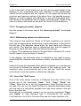
10.1. Automatical calculation after input................................................... 76
10.2. Sounds................................................................................................. 76
10.3. Connections with ConCrete Plus ...................................................... 76
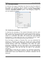
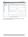
10.4. Showing more diagrams or limit states ........................................... 78
10.5. Sign conventions for moment and shear force ............................... 80
10.6. Close-up of a diagram in a zone ....................................................... 81
10.6.1. Making a close-up ............................................................................ 81
10.6.2. Changing to another diagram ........................................................... 82
10.6.3. Withdrawing values in isolated points .............................................. 82
10.7. Use of the "Edit"-menu ...................................................................... 82
10.8. Calculation method ............................................................................ 83
10.9. Verification calculation ...................................................................... 83
10.10. Saving and retrieving preferences in files ..................................... 84
10.11. Adapting ConCrete’s environment ................................................. 84
CHAPTER 11 OVERVIEW OF THE MENU'S ..................................... 87
11.1. "File"-menu ......................................................................................... 88
11.2. "Edit"-menu ......................................................................................... 88
11.3. "Element"-menu ................................................................................. 88
11.4. "Window"-menu .................................................................................. 89
11.5. "Preferences"-menu ........................................................................... 89
11.6. "Help"-menu ........................................................................................ 90
5
BuildSoft n.v.
User’s manual ConCrete
Chapter 1 Introduction
6
BuildSoft n.v.
User’s manual ConCrete
1.1. Hard- & software requirements
ConCrete is a 32-bit software program for the MS Windows operating
system. Although it may be possible to run ConCrete on previous
versions of MS Windows (without any warranty from BuildSoft, however),
it is highly recommended to use it on MS Windows 98, Me, XP, Vista or
7.
1.2. Installing ConCrete
The ConCrete software can be installed from CD-ROM or over the
internet. In this case, you should have a valid LOGIN and PASSWORD
to access the “Customer Care” section of the BuildSoft web site
http://www.buildsoft.eu. BuildSoft customers receive access to this
protected section as part of their maintenance or lease service contract.
Other people interested in evaluating ConCrete receive valid access data
for a 30- days period provided they register at the BuildSoft web site. In
case all defaults are accepted as proposed by the ConCrete installation
procedure, the software will be installed on the directory “C:\Program
Files\Buildsoft\ConCrete”.
1.3. ConCrete, ConCrete Plus and ConCrete List
ConCrete belongs to a package of 3 programs which together manage
the design process of reinforced concrete beams.
The ConCrete module automises the static and organic calculation of
continuous beams and slabs (in one direction) of reinforced concrete.
The ConCrete Plus module uses these results for generating the
reinforcement plans.
The ConCrete List module creates the bar schedules of the used
reinforcement steel.
Apart from ConCrete, ConCrete Plus and ConCrete List we can use a
CAD program for completing the reinforcement plans. In ConCrete Plus
the data can be transferred to AutoCad, VersaCad, Microstation,
Speedikon, Architrion, Tech2D or any other program that reads DXF
format.
7
BuildSoft n.v.
User’s manual ConCrete
Chapter 2 A simple beam
8
BuildSoft n.v.
User’s manual ConCrete
2.1. Introduction
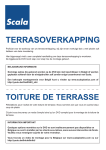
We will now get used to the working method of ConCrete by means of a
simple example. Let us consider a beam of one span.
Figure 1 : Sketch of the first example
The length is 5 m and the beam is loaded over its full length with a
uniformal distributed load = ݍ20 ݇ܰ/݉. The width of the beam is set to
190 mm, the heigth to 450 mm.
Remark: all examples in this manual are calculated with EN 1992 1-1 (B).
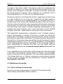
2.2. Creating a new project
After having started ConCrete we select in the File menu the first
command "New…".
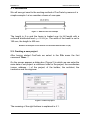
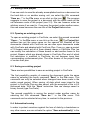
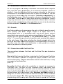
On the screen appears a dialog box (Figure 2) in which we can enter the
main data of our project: a reference code for the project, the coordinates
(name, address,…) of the project, of the builder, the architect, the
contractor and the engineer.
Figure 2 : Data of a project
The meaning of the right buttons is explained in 4.1.
9
BuildSoft n.v.
User’s manual ConCrete
We leave the dialog box by clicking the "OK"-button (with the mouse or
by pressing the ENTER- or RETURN-key).
On the left side of the screen appear two palettes (Figure 3 & Figure 4)
and in the bottom left corner a window (Figure 5), with two empty lists in
it and with the reference code "CONCRETE" as header in the title bar.
From now on we will call this window the Project list-window.
Figure 3 :
Palet 1
Figure 4 :
Palet 2
Figure 5 : Project list
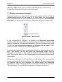
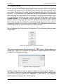
2.3. Entering a new element
Now it is possible to select the Element menu. We select the first
command "New beam" in the Element menu or click the icon
.
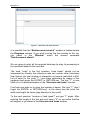
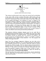
At the top of the screen an input panel appears (with the indication
"code beam?) (Figure 6).
Figure 6 : Code beam
Three extra windows are added with resp. heading "Structure and
loads", "Diagrams" and "Reinforcement sketch". The two last
mentioned windows are empty, the Structure and loads window already
contains some information.
10
BuildSoft n.v.
User’s manual ConCrete
Figure 7 : Structure and loads window
It is possible that the “Reinforcement sketch” window is hidden behind
the Diagrams window. If you wish to bring the first window to the top,
you select in the “Window” menu the second command
“Reinforcement sketch”.
We are going to enter all the required data step by step, by answering to
the questions asked in the input bar.
The word "code" in the first question "code beam" should not be
interpreted too literally; the reference code can contain other characters
than figures; the total number of characters is however restricted to 256.
Let us enter for the code "1": type these characters by means of the
keyboard and press the ENTER- or RETURN-key. The text "1" is now
filled out in its destinated place in the “Structure and loads” window.
ConCrete now asks us to enter the number of spans. We type "1" (don’t
forget the ENTER- or RETURN-key!). In the same way we enter the
width and height the beam (pay attention to the units!).
To the next question "number of load types?" we type "1" again. After
entering the length of the first and only span ("5" m) we notice that the
left support is yet drawn in the Structure and loads window.
11
BuildSoft n.v.
User’s manual ConCrete
Figure 8 : Structure and loads window - input
To the question "number of zones in 1° span?" the p rogram suggests the
answer "1" ; we confirm this by pressing the ENTER- or RETURN-key.
Finally we type the value "20" to the question "value distributed load nr. 1
zone z1.1? (kN/m)". After pressing the ENTER- or RETURN-key, the
program automatically calculates the entered beam. The windows
"Structure and loads", "Diagrams" and "Reinforcement sketch" are
completed with the results of the calculations.
2.4. Interpretation of the calculated results
The results of the calculations are spread over the three windows
"Structure and loads", "Diagrams" and "Reinforcement sketch".
12
BuildSoft n.v.
User’s manual ConCrete
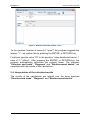
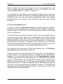
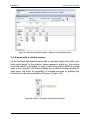
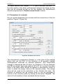
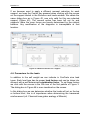
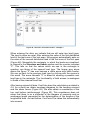
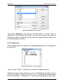
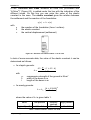
2.4.1. The "Structure and loads”-window
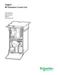
Figure 9 : Structure and loads window - results
Clicking the icon
makes the “Structure and loads” window visible.
In this window (Figure 9) the minimum and maximum vertical reactions
in Ultimate Limit State (U.L.S.) of each support are indicated. Upward
reactions are considered positive. The minimum and maximum value are
here 55.34 and 74.71kN. These values are the result of the reaction due
to the introduced load and the self weight (25 kN/m³). The minimum
value is obtained by considering both loads with load coefficient = 1.0
(load factor for dead loads with favourable effect). The value 55.34 can
be explained as follows :
(20 + 25 ∙ 0.19 ∙ 0.45) ݇ܰ/݉ ∙ 5݉ / 2 = 55.34 ݇ܰ
The maximum value is obtained by considering both loads with load
coefficient = 1.35 (load factor for dead loads with unfavourable effect).
The value 74.71 can be explained as follows :
1.35 ∙ (20 + 25 ∙ 0.19 ∙ 0.45)݇ܰ/݉ ∙ 5݉ /2 = 74.71 ݇ܰ
The maximum and minimum moment reactions in Ultimate Limit State
(U.L.S.) are indicated under the vertical actions: since we deal with
simple supports (without any restraint to rotation) the minimum and
maximum value are both equal to 0.00kNm. Moment reactions which
work counter clock-wise are considered as positive.
13
BuildSoft n.v.
User’s manual ConCrete
Information on the dimensioning of the beam is indicated in the three
remaining lines under the moment reactions. On the first line we notice
as optimum height the value 470 ; this is the optimum height of the beam
in mm. The optimum height is the height at which the concrete is
subjected to a compressive strain of 3.5‰ and the steel to a tensile
strain of 10‰, in other words the height at which the components of the
reinforced concrete are used in an optimum way. On the next line the
minimum height is indicated, here 346 mm. The minimum height is the
height which just meets the requirements to resist to the solicitations
without needing any compression reinforcement ; in other words, if we
should choose a smaller height the beam would collapse by smashing
the concrete if we did not foresee compression reinforcement. Only when
the entered height is smaller than the optimum height the two higher
mentioned values are indicated in the Structure and loads window. For
beams, these values are only determined by bending.
When the cross section does not meet the requirements to resist the
shear force, the minimum width at which the concrete compression
struts in the classical truss girder analogy of Mörsch just fail to get
smashed. For slabs, the minimum section of the compression struts is
inclined in the calculation of the minimum height.
Important: the values for optimum height, minimum height and width are
related to the Ultimate Limit State. How ConCrete handles the
Serviceability Limit State will be explained further on.
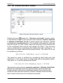
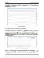
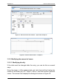
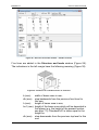
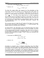
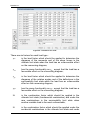
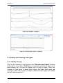
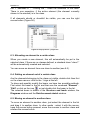
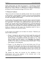
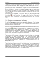
2.4.2. The "Diagrams”-window
In the menu “Window” select the second item “Diagrams” or click the
icon
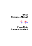
. In this window (Figure 10) we notice a schematic
representation of the entered beam, diagrams for shear forces and for
bending moments in ultimate limit state and the required reinforcement
quantities. Right of the diagram, the extreme values in negative and
positive sense and the units are indicated. Further on in this manual we
will learn how we can show the diagram of rotation angles and
deflections in this window (10.4) and how we can change the sign
convention of the shear force V and the bending moment M (10.5).
The reinforcement diagram takes a shift of the moment-line into account
over a distance a = z . (cot θ – cot α) / 2. Compression reinforcement is
always red and indicated with a negative value, the black dashed line
represents the amount of tensile reinforcement for which only the
ultimate limit state requirements; the black solid line is the amount of
tensile reinforcement required for the serviceability limit state. The
14
BuildSoft n.v.
User’s manual ConCrete
horizontal dotted lines (indicating 117) set the minimum amount of
longitudinal reinforcement (here corresponding to a reinforcement
percentage ߩ = 0.0015).
Figure 10 : Diagrams
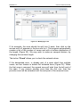
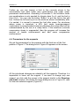
2.4.3. The "Reinforcement sketch”-window
When this window is still hidden by the “Diagrams”-window, we bring it
to top by selecting the second command "Reinforcement sketch" in the
Window menu or click
. In this window (Figure 11) we can see a
schematic representation of the front view of the beam with indication of
the reinforcement.
Figure 11 : Reinforcement sketch
Above the beam sketch we see a measuring line with above it the
encircled figures "1", "2" and "3" and under it the figures "1.08", "3.00"
and "0.82". We should interpret this as follows. The encircled figures are
15
BuildSoft n.v.
User’s manual ConCrete
related to the stirrups and are a reference to the information which is at
the right of the beam sketch. The figures under the measuring line
indicate the distance in m along which the mentioned stirrups have to be
placed. In the information on the right "4 stirrups ø 6 all 270" means that
we should provide 4 stirrups with a diameter of 6 millimeter with a
theoretical distance of 270 mm over the indicated length.
We always assume in ConCrete that the first, respectively the last stirrup
in a span is placed at 5 cm of the left-, respectively the right support of
the span. If there are more stirrup zones (in our example there are 3)
the left arrow of the stirrup zone indicates the place of the first stirrup of
that zone when the previous zone is provided with a heavier transverse
reinforcement: the right arrow indicates the place of the last stirrup when
the next stirrup zone needs a heavier transverse reinforcement. In our
example, the arrows between zone 1 and 2 and zone 2 and 3 indicate
the place of the first-, respectively the last stirrup of the second zone.
The longitudinal reinforcement is indicated in mm². At places where a
bottom reinforcement is required, a bold line is drawn just above the
bottom side of the beam: in case of top reinforcement, the line is drawn
just below the upper side of the beam. The beginning and ending point of
this bold line, is the place where the shifted moment-line doesn’t require
reinforcement anymore (see 2.4.2). The determination of the diameters
of the longitudinal bars and the calculation of the anchorage length is
done automatically in Concrete Plus. We can now easily read the
required reinforcement from the Reinforcement sketch window with this
information.
In our example we only need bottom reinforcement over the entire length
of the beam. The maximum required section is 757mm². We could place
here e.g. two bars of 25 mm diameter. The red-marked negative quantity
-160 means that there is 160mm² compression reinforcement required
on top in order to comply with the limitations for concrete stresses in
Serviceability Limit State.
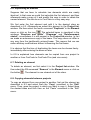
2.5. Modifying entered data
2.5.1. Direct editing of entered data
One of the numerous advantages of ConCrete is the simplicity with
which already entered data can be modified.
16
BuildSoft n.v.
User’s manual ConCrete
All the data entered, can be modified at any time by clicking the value
with the mouse in the Structure and loads window, except for 3 data
types:
• number of spans, this number can never be less than the number
of already present spans. (see 2.5.1.3)
• number of zones, which can only be modified after completely
entering the beam. (see 3.2.3)
• number of load types, which can only be modified after completing
the current beam or before entering the second load type. (see 5.3)
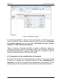
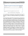
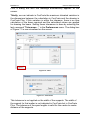
Let us, for example, change the span length of 5 m into 4.95 m. Select
therefore the figure "5.00" in the Structure and loads window. When
moving with the mouse over the value, the value is highlighted. After
selecting this value, the value is framed and appears in the input bar with
the following question: "length 1° span? (m)" (Figu re 12).
Figure 12 : Adjusting the length of a span
We now type the figure "4.95" and confirm it by pressing the ENTER- or
RETURN-key. As soon as we have pressed this last key, the beam is
automatically recalculated and all results are adapted in their window.
We can notice e.g. that the required section for bottom reinforcement has
dropped from 757 mm² to 727 mm² and from 160 mm² to 144 mm² for
17
BuildSoft n.v.
User’s manual ConCrete
the top compression reinforcement. If you change the height of the beam
from 450mm to 500mm, the bottom reinforcement will be 516mm² and
the compression reinforcement 6mm².
Thanks to the flexible method of modifying the data ConCrete enables
you to really dimension. When we initially enter an arbitrary low value
for the width and height of the beam, the program tells us after
calculation how much we need minimally and optimally. In order to obtain
a section which is neither too big nor too small, you only have to change
the initial low values into higher ones, taking the minimum and optimum
values into account.
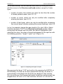
When the number of spans is altered, the program will ask, depending
wheather the number of spans is enlarged or reduced, where the spans
should be added (Figure 13) or removed (Figure 14).
Figure 13 : Enlarging number of spans
Note the choice to duplicate spans. Indicate this checkbox if the added
spans must be a copy must be of the previous (when adding a span
before the first span, the span added will be a copy of the first span).
18
BuildSoft n.v.
User’s manual ConCrete
Figure 14 : Reducing number of spans
2.5.2. Modifying with the right mouse button
A second way to modify the entered values is to use the mouse. For
example, right-click the name of the length of the span, there appears a
so-called popup menu with some items:
Figure 15 : Pop-up menu – span
19
BuildSoft n.v.
User’s manual ConCrete
The first item “Remove” is only available when there is more than one
beam span.
The item "Add" allows you to add a standard span before or after the
appointed span, while "Duplicate" copies the current span.
Such a function also exists for editing the loads. Either you select the
values of the loads one by one, or you can use the right button of the
mouse. With the popup menu that appears, you can quickly copy the
value of a loads to other fields.
Figure 16 : Pop-up menu – Copying loads
What happens when you changes the amount of load types, will be
discussed in 5.3.
The editing of the zones will be handled in 3.2.3.
20
BuildSoft n.v.
User’s manual ConCrete
Chapter 3 A second beam
21
BuildSoft n.v.
User’s manual ConCrete
3.1. A beam in the Projectlist-window
To enter a new beam, we select the first command "New beam" in the
Element menu of click the icon
is now saved in the project.
. The previous beam, named “beam”,
Figure 17 : Project list
The list is constructed as a tree. The main items are the classes, the
subitems are the elements. Currently, only one element is calculated.
The second beam has yet to be defined. Both elements are in the first
class. The date that the element was last opened is mentioned behind its
name. Moreover, the most recent date is listed next to the header of the
window itself.
3.2. Concentrated & trapezoidal forces
In chapter 2 we saw how to enter and how to calculate a beam of one
span with a uniform distributed load. We now enter a beam of two spans
and with a less simple load (Figure 18). The width of the beam is set to
190 mm, the height to 450 mm.
Figure 18 : Sketch of the second example
22
BuildSoft n.v.
User’s manual ConCrete
The input will be completely similar to that described in chapter 2, but
take care of the number of spans and consider the remarks 3.2.1 and
3.2.2 before entering the element.
3.2.1. Trapezoidal forces
The trapezoidal force is entered as follows. Select with the Mouse in
the second pallet (Figure 19, Figure 4) the second icon. When the button
is lowered, trazoidal loads can be entered.
Figure 19 : Palet 2 – Uniformally / Trapeziodally distrusted loads
Figure 20 : Structure and loads window – distributed load
An extra line is added in the Structure and loads window (Figure 20).
The begin values of the distributed loads will be indicated on the line
which is proceeded by “p1 (kN/m)” in the left margin; the end values on
the line below, proceeded by “p2 (kN/m)”.
23
BuildSoft n.v.
User’s manual ConCrete
When entering the data, the program will ask two questions for two
values : "begin value distributed load nr. 1 zone z1.1?(kN/m)" and "end
value distributed load nr. 1 zone z1.1?(kN/m)".
It is important to know that we can modify this option at any time: this
means that even when the beam is completely entered with a uniformal
distributed load, we can still choose trapezoidal loads and change
possible begin or end values of the distributed loads by simply clicking
the value.
3.2.2. Concentrated forces
In order to enter a concentrated force we should provide a division
between two zones where the concentrated force is situated. A zone is a
part of a span in which there are no discontinuities neither in the loads
nor in the geometry.
This means that we should foresee two zones in the second span, that is
to say one left and one right of the concentrated force. When entering
data, the program asks, after input of the begin and end values of the
distributed force in the first zone of the second span (z2.1), the place of
the end point of that zone. The place of the end point of a zone is the
distance between this point and the left support of the span to which the
concerning zone belongs. In our example this distance is 2 m.
If we now also enter the value of the concentrated force, our Structure
and loads window will be like in Figure 21.
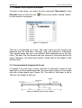
We then continue to enter the beam in the usual way. The interpretation
of the results in the different window is similar to that described in
chapter 2. In the bottom right corner of the Reinforcement sketch
window (Figure 22) we notice a button with a ">"-sign. When we click the
mouse on that button, the reinforcement sketch of the second span
appears. The button with the ">"-sign has now disappeared. At the same
time a button with a "<"-sign has become visible ; by clicking this sign we
can return to the previous span. As stated in chapter 2, the begin and
end points of the indicated reinforcement are the points of zero of the
shifted bending moments diagram.
24
BuildSoft n.v.
User’s manual ConCrete
Figure 21 : Structure and loads window – input loads example 2
Figure 22 : Reinforcement sketch – example 2
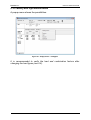
3.2.3. Modifying the amount of zones
3.2.3.1. Modifying directly
If the data must be changed after the entry, you can do this on several
ways.
Once the beam is fully implemented, just click the bold text below the
sketch of the beam (eg "z2.1" span 2, Zone 1) with the mouse to add the
zones. The screen then displays the dialog box shown in Figure 23.
25
BuildSoft n.v.
User’s manual ConCrete
Figure 23 : Modifying a zone
If for example, the zone should be split into 2 parts, then click on the
arrows until a 2 appears in the box next to it. The program automatically
creates a list of the number of zones and with a uniform distribution of
the length (Figure 23). We may wish to make an unequal division, by
changing the sections length.
The button 'Check' allows you to check the entered values.
If the designated area is already part of a span which has multiple
zones, we can choose to delete the indicated zone (Figure 24). When
the first zone is removed, the second zone will start from the left end of
the span. If you remove another zone then the first one, then the
previous zone will be extended until the end point of the removed zone.
26
BuildSoft n.v.
User’s manual ConCrete
Figure 24 : Modifying a zone 2
3.2.3.2. Modification by using the right mouse button
The zones can also be manipulated using a popup menu. To do so,
right-click the name of the zone:
Figure 25 : Popup menu - zone
The first item "Delete" will only be selectable if the span consists of more
than one zone.
27
BuildSoft n.v.
User’s manual ConCrete
The item "Add" allows you to create an additional zone. The function
divides the designated area into two equal parts.
3.3. Adding concentrated moments
Suppose that we not only wish to enter a concentrated force but also a
concentrated moment with a value of 10 kNm where the concentrated
force is situated. We do so by selecting the input choice "concentrated
moments" via the third icon in the second pallet of Figure 4 (Figure 26).
Figure 26 : Pallet 2 – Moment button
A line, proceeded by "M(kNm)", is added to the Structure and loads
window under the line of the concentrated forces (Figure 27). This line
serves for entering concentrated moments. We can now enter the value
"10.00" for the concentrated moments by selecting the set value "0.00"
under the value "15.00" of the concentrated force.
Concentrated moments are considered as positive when working clockwise. This option, just as the option for trapezoidal forces, can be
changed at any time. If this option is already selected when entering
data, the program asks for the concentrated moments when the entrance
takes place.
Please pay attention to the fact that we can also enter concentrated
forces and moments at the location of the supports. Concentrated forces
on supports can be very important for beams which are supported
elastically or when taking the loads of the upper columns into account.
The importance of concentrated moments on supports is obvious.
28
BuildSoft n.v.
User’s manual ConCrete
Figure 27 : Structure and loads window – adding a concentrated moment
3.4. A beam with a variable section
So far we have calculated beams with a constant height and width over
their entire length. In the practice, cases appear in which e.g. the section
is not the same for all spans, or even in which the section within a certain
span is not constant. ConCrete enables you to define another section for
each zone. We enter the possibility of variable sections by pushing the
first button in the second palette of Figure 4 (Figure 28).
Figure 28 : Pallet 2 – Constant / variable section button
29
BuildSoft n.v.
User’s manual ConCrete
Figure 29 : Structure and loads window – Variable sections
Five lines are added in the Structure and loads window (Figure 29).
The indications in the left margin have the following meaning (Figure 30):
Figure 30 : Distances of a variable section in ConCrete
b (mm):
db (mm):
width of beam zone in mm;
step backwards from the previous front level to
this one;
h (mm):
height of beam zone in mm;
ho1 (mm): height of the beam zone which will be deposited in
first phase (e.g. the height of the precast section,
see also 7.3). Standard h01 is taken equal to the
height ho.
dh (mm): step downwards from the previous top level to this
one.
30
BuildSoft n.v.
User’s manual ConCrete
The values for "b (mm)", "h (mm)" and "dh (mm)" can be changed in the
same way as all other data in the Structure and loads window. The
value of "db (mm)" cannot be changed; it is calculated as being half of
the difference in width with the previous zone. The reason is that an
asymmetrical jump in the width causes torsion and ConCrete does not
include torsion in its calculation.
If we e.g. change the height in zone z2.1 to 350 mm, the word "VAR" is
automatically filled out at the place in the Structure and loads window
where the general valid height of the beam is indicated. This means that
the beam has a variable height. At the same time a recalculation of the
beam has taken place. We can see the jump in the Reinforcement
sketch window. In the Diagram window, the development of the required
reinforcement is clearly represented (Figure 31).
Figure 31 : Reinforcement sketch – variable section
Some considerations :
1) When determining the reinforcement section at the place of the
change of section the program takes the fact into consideration that the
diagram of moments has to be shifted over a distance δ (Figure 33). This
means that the reinforcement section required at a certain place, is the
maximum within a zone with length 2 δ (centralized around the
considered point) of the reinforcement sections calculated from the
unshifted diagram of moments.
31
BuildSoft n.v.
User’s manual ConCrete
Figure 32 : Diagrams – example 2
Figure 33 : Shifted moment-line
2) The reinforcement sections are determined by also taking the fact into
account that bars, which work at the bottom of the bigger beam section,
only become effective after acquiring a certain length. This length is
determined by the anchorage length increased with the transfer length
needed to transfer forces from one bar level to the other (Figure 34). The
program takes as anchorage length a constant value of 60 cm because
we have not yet determined bar diameters. In the zone with length equal
to the transfer length plus 60 cm, ConCrete assumes for the
determination of the required mm² reinforcement that the working section
varies linear.
Figure 34 : Reinforcement – anchorage and transfer length
32
BuildSoft n.v.
User’s manual ConCrete
The jump in de required reinforcement diagram is due to the presence of
the external moment of 10 kNm.
33
BuildSoft n.v.
User’s manual ConCrete
Chapter 4 Calculation parameters
34
BuildSoft n.v.
User’s manual ConCrete
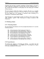
4.1. Project values
So far we have calculated beams reinforced concrete without e.g. asking
ourselves the question, out of which steel quality the reinforcement bars
are made. This does not mean that the program does not take that into
account ; it is however not necessary to set all calculation parameters
when starting the calculation of an element. ConCrete automatically uses
the standard set values as basic values. We call these basic values the
project values. It is however always possible to deviate from these
project values at any time and even to set new values as project values.
Each time we start ConCrete the calculation parameters are set equal to
the project values. If we enter a new element, the calculation parameters
remain equal to the current values of at that moment.
We will always find 5 buttons at the bottom of the following dialog boxes
(Figure 35).
Figure 35 : Dialog boxes – the 5 basic buttons
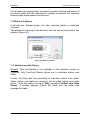
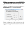
The current values are set by pressing the "OK" button. There appears a
dialog box (Figure 35) in which you indicate on which elements you want
to apply the changed settings.
Figure 36 : Adjust current values
Current values can be set as project values by pressing the "Store" or
"S" button. When the current values deviate from the project values they
can be set equal by pressing the "Retrieve" or "R" button. The "Cancel"
button does not change the current values.
35
BuildSoft n.v.
User’s manual ConCrete
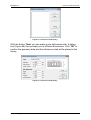
4.2. Parameters for reinforcement steel
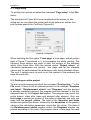
Figure 37 : Parameters for reinforcement steel
We can take a look at and change the parameters of the reinforcement
steel by clicking the first icon of the first palette of Figure 3: now a new
dialog box appears on the screen (Figure 37). In this dialog box we can
change all the parameters of the reinforcement steel freely. The values
of the steel quality are characteristic values and are expressed in N/mm².
The safety factor is the factor which has to be applied to the
characteristic values in order to obtain the design value of the steel
quality. This design value will be used in the ultimate limit state. In the
serviceability limit state under the rare combinations the maximum stress
can be limited to a fraction of the yield stress (80% according to
Eurocode). The cover is the net distance between the bar and the outer
surface of the concrete, as indicated in Figure 38. When calculating the
effective depth, the real height of the beam is decreased with this cover
and with 10 mm extra to take the thickness of the reinforcement bars into
account (which are unknown at that moment).
36
BuildSoft n.v.
User’s manual ConCrete
Figure 38 : Sketch of the concrete coverage
The minimum reinforcement ratio is taken into account by the calculation
of the crack width and the cracked deformation. Both bottom and top
reinforcement can be taken constant over the whole span length. The
amount of reinforcement has a favourable effect on the crack width and
on the cracked deformation. The meaning of "crack" is related to the
truss girder analogy of Mörsch, in which a reinforced concrete beam is
visualised as a truss girder with inclined concrete compressive struts,
vertical stirrups and horizontal longitudinal reinforcement. The height of
the truss girder is 0.9 times the effective depth. The reason for the
inclined concrete compressive bars is that shear force cracks always
have a slope. The horizontal length of such a tear is function of the
slope. By keeping the stirrup distance constant over a certain number of
cracks, we obtain a much more practical stirrup distribution.
The minimum distance between stirrups can be set, and this in
longitudinal and transverse direction. This enables you to opt for a lower
longitudinal distance or for multiple stirrups. If the calculation shows that
the distance should be smaller than the minimum set distance, the
program keeps the calculated distance, unless it is possible to obtain a
larger distance with a bigger stirrup diameter. If so, the program will
choose the bigger diameter.
Apart from the minimum transverse distance, we can also set a
maximum transverse distance. This is normally defined by the standard.
Most standards demand that the maximum transverse distance remains
less than the effective height, which for almost square sections leads to
multiple stirrups. To avoid this, you can impose a proper maximum (e.g.
200 mm). In case where one stirrups isn’t enough, the program will try to
solve the problem by adding a single hook in order to have a 3 bars –
stirrup. You can however force the program to apply two stirrups by
checking the option “no single hooks allowed”.
The bar diameters that may be used for the stirrups, can be indicated by
the user. Apart from the standardised diameters 6, 8, 10 and 12, a free
value can be entered.
37
BuildSoft n.v.
User’s manual ConCrete
For beam sections with flanges (T, I-, L- and Z-sections, see also 7.1)
the steel quality of the shear reinforcement between the flange and the
web can be indicated as well as the fact whether this reinforcement
should be represented in ‘Reinforcement sketch’ window.
4.3. Parameters for concrete
We can set the parameters for concrete with the second icon of the first
palette of Figure 3 (Figure 39).
Figure 39 : Parameters for concrete
The characteristic compressive strength ݂ is the value of the strength
above wich we find 95% of the collection of all possible strength
measurements exercised on concrete specimen. This compressive
strength is determined after 28 days, on cylinders of 150 mm diameter
and 300 mm height, kept under water at 20 ± 2°C. As for steel, the safety
factor is the factor which should be applied to characteristic values in
order to obtain the design value of the concrete quality. This design
value will be used for the calculation in the ultimate limit state. The
modulus of elasticity can be entered freely or can be calculated in
function of the concrete quality by clicking on the button “Ecm,28”. The
value of the E-modulus is than calculated with the formula:
38
BuildSoft n.v.
User’s manual ConCrete
• Eurocode 2 and NBN B15-002:
ܧ,ଶ଼ = 9500 ∙ (fୡ୩ + 8)ଵ/ଷ
• B.A.E.L. 91:
ଵ/ଷ
ܧ,ଶ଼ = 11000 ∙ ݂
To take the creep effect into account by the calculation of the
deformation and by the limitation of the stress and the crack width, the
creep factor ߶(ݐ, ݐ ) can be introduced. Traditionally the stresses are
limited for a ratio between the E-moduli of steel and concrete equal to
ா
15: ݊ = ೞ = 15. The value of the creep factor ߶(ݐ, ݐ ) that corresponds
ா
with this ratio can be calculated by clicking on the button "n = 15". This
value is not the final creep factor. When using this value, the result for
the deformation will theoretically be underestimated. However, if we use
all recommended values, the calculated deformation exceeds the
experimental result.
We can also choose to take the self weight of the beam into account,
with or without the weight of the flanges for T-, I-, L- and Z-sections. The
specific gravity of concrete is set to 25 kN/m³.
As stated before, the deformation can be calculated taking the cracks
into account, i.e. using decreased stiffness. For this calculation, the value
of the concrete tensile strength is important. The value can be set free or
be calculated as the mean (݂௧ ) or characteristic (݂௧ = ݂௧.ହ ) value in
function of the compressive strength. These 2 values are calculated with
the next formulas:
• Eurocode 2 en NBN B15-002:
ଶ/ଷ
݂௧ = 0.30 ∙ ݂
݂௧.ହ = 0.7 ∙ ݂௧
• B.A.E.L. 91:
݂௧.ହ
0.7
= 0.6 + 0.06 ∙ ݂
݂௧ =
݂௧.ହ
According to research done at Magnel Laboratory from the Ghent
University, both these lead to a higher calculated deformation than the
test results. In that research, they conclude that the value of 3.56 N/mm²
(for C25/30) which is proposed in the American Standard, is more in
comparison with the test results. It’s our opinion that without too much
risk, the deflection can be calculated with the previous mentioned factor
n = 15 and with the mean tensile strength ݂௧ = 2.56 N/mm² .
39
BuildSoft n.v.
User’s manual ConCrete
Further on, you can impose a limit to the concrete stress in the
serviceability limit state under rare combinations and under quasipermanent combinations. According to Eurocode 2, the limitation under
rare combinations is only needed for climate class 3 or 4, and the limit is
then 0.6݂ . You can use the button “0.6ࢌࢉ ” to put this limit in the edit
box. Unless the full load is put on the structure almost immediately after
it is casted, it is normal to impose this limit after creep. For structures
where creep is important, a 45% limit under quasi-permanent
combination is recommended, because otherwise the creep effect will be
underestimated by the use of a creep factor. If the maximum concrete
compressive stress is superseded, than the program will increase the
amount of tensile reinforcement and add some compression
reinforcement.
4.4. Parameters for the supports
We set the parameters for the supports with the third icon of the first
palette of Figure 3. The dialog box of Figure 40 appears on the screen.
Figure 40 : Standard support
All the introduced changes are related to all the supports. Therefore it is
impossible to leave out the support. If we want to change only one
support, we click with the mouse in the support sketch in the Structure
and loads window. We obtain the same dialog box as in Figure 40, valid
for this one selected support (Figure 41).
40
BuildSoft n.v.
User’s manual ConCrete
Figure 41 : Adjusting a support
It is however possible to leave out an end support. In that way we can
make a cantilever from a simple supported span. Except for cantilevers
and simple supports, we can also enter translation springs, rotation
springs and fully restrained supports.
There is however a second possibility to enter a cantilever, namely by
entering a negative value for the span length of an end span. ConCrete
automatically interprets a negative span length as a cantilever with as
length the absolute value of the entered length.
4.5. Parameters for the redistribution of moments
We select the fourth icon of the first palette of Figure 3 if we want to take
a look at or change the calculation options of the redistribution of
moments. Just as for the geometrical parameters of the supports, these
options apply to all the supports (or only all the intermediate supports).
41
BuildSoft n.v.
User’s manual ConCrete
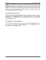
Figure 42 : Parameters for the redistribution of moments
The first option in the dialog box (Figure 42) causes no change in the
diagrams, it only produces a reduction of the reinforcement moments.
The reason therefore is that with larger supports, the top of the diagram
of moments can be cut in order to determine the support reinforcement
(Figure 43).
Concrete allows you to reduce the time by either:
- By giving up a percentage
- By giving up the width of the supports.
The reduction of the moment ∆ ܯis calculated as follows:
ܨ௦௨ ∙ ܾ௦௨
∆= ܯ
8
In which ܨ௦௨ is the reaction force in the support and ܾ௦௨ the width
of the support.
On the contrary, the second option does change the diagrams by
decreasing the moments on the intermediate supports with a percentage
entered by the user and by increasing at the same time the moments in
the spans so that the obtained diagram of moments is, from a static point
of view, a correct solution for the entered loads (Figure 44). This
implicates that the shear force line is also changed.
Figure 43 : Moment reduction without
redistribution
Figure 44 : Moment reduction with
redistribution
42
BuildSoft n.v.
User’s manual ConCrete
If we however want to apply a different moment reduction for each
support, we keep the Control key pressed when clicking with the mouse
on the support sketch in the Structure and loads window. We obtain the
same dialog box as in Figure 42, now only valid for this one selected
support (Figure 45). The second option has been left out for end
supports: there the inner forces are merely determined by the statical
balance. Any modification of the diagrams is inacceptable at that
location.
Figure 45 : Moment reduction on a support
4.6. Parameters for the loads
In addition to the self weight we can indicate in ConCrete nine load
types. Each load type has its proper load factors and can be taken into
account with a well determined combination factor. To set these factors
we click with the mouse in the fifth icon of the first palette of Figure 3.
The dialog box in Figure 46 is now visualized on the screen.
In this dialog box we can determine whether the loads will act on the top
or bottom level, this is of importance when determining the transverse
reinforcement (cfr. Classical truss girder analogy of Mörsch).
43
BuildSoft n.v.
User’s manual ConCrete
Figure 46 : Parameters for loads
There are six factors for each load type :
ߛ௨ି
is the load factor which should be applied to determine the
diagrams of the moments and of the shear forces in the
ultimate limit state when the load has an unfavourable effect
on the concerning diagram;
ߛ௨ା
ߛି
ߛା
ߖ
ߖଵ
has the same functionality as ߛ௨ି except that the load has a
favourable effect on the concerning diagram;
is the load factor which should be applied to determine the
diagrams of the rotation angles and of the deflections in the
serviceability limit state when the load has an unfavourable
effect on the concerning diagram;
has the same functionality as ߛି except that the load has a
favourable effect on the concerning diagram;
is the combination factor which should be applied in the
ultimate limit state (fundamental combination) and under the
rare combinations in the serviceability limit state when
another variable load is the most unfavourable;
is the combination factor which should be applied under the
accidental combinations in the ultimate limit state and under
44
BuildSoft n.v.
User’s manual ConCrete
the frequent combinations in the serviceability state when this
variable load is the most unfavourable.
ߖଶ
is the combination factor which should be applied under the
quasi-permanent combination in the serviceability limit state.
Under the accidental combination un the ultimate limit state
and under the frequent combination in the serviceability state
this factor is applied when another variable load is the most
unfavourable.
The load on a cantilever e.g. is favourable to the moments in the span
beside ; for the calculation of these moments the program will apply on
this load the factor ߛ௨ା ; for the moment in the cantilever however, the
program will apply the factor ߛ௨ି . For the determination of the application
of the favourable or unfavourable factor in order to calculate the moment
in a determined point, the program assumes that the considered load
within a span, is present either with the favourable or with the
unfavourable factor. When determining the moment in an arbitrary point
ݔଵ , the load which continues over several spans can be present in one
span with the unfavourable factor and in another span with the
favourable factor. In another point x2 these factors can be the other way
round. The program finds out for itself which factors should be applied. It
is obvious that what we considered as valid for the diagram of moments
is also valid for the other diagrams.
When determining the fundamental combination in the ultimate limit state
(U.L.S.) and the rare combinations (R.C.) in the serviceability limit state,
the most unfavourable variable load is taken with a combination factor 1,
all other variable loads are taken with their combination factor ߖ . Just
like for the load factors, the program finds out by itself which variable
load is the most unfavourable for the considered point. In the quasipermanent combination all variable loads are applied with their
combination factor ߖଶ . Permanent loads are always combined without
combination factor (i.e. combination factor = 1).
Please notice that when determining the load types we do not make a
difference between permanent and variable loads. This means that we
also have a favourable and an unfavourable factor for permanent loads
as well as for variable loads. For variable loads we will enter the value
"0" as favourable load factor, for permanent loads this value will always
be around "1", e.g. "0.9".
The difference between permanent and variable is only made by entering
other values for the load- and combination factors.
45
BuildSoft n.v.
User’s manual ConCrete
For each load type it is possible to indicate in which phase(s) the loads of
this type are present. The first phase is calculated in an isostatic way
(span by span), possibly with a reduced height (ho1 instead of ho). The
required reinforcement for the ultimate limit state is calculated. Then, the
beam is calculated in the second phase. In this phase, the beam is
calculated in its hyperstatic condition, with the full height (ho). Again, the
reinforcement for the ultimate limit state is calculated. The final result for
the ultimate limit state is the maximum of the first and second phase.
Starting from this reinforcement, the stresses in the serviceability limit
state in the concrete and in the reinforcement are calculated in the first
phase (thus in an isostatic way and with reduced height). Then the
increase of stresses in the second phase is determined. If the stresses
are too high, the reinforcement is increased.
With the parameter “always together” you can force the program to
consider the loads of a load type always as one undividable load.
Otherwise, ConCrete will automatically load some spans with the
favourable load factor and other with the unfavourable load factor to
obtain the most damaging load situation. It can be however that the
nature of the load makes it impossible to vary the load over different
spans between favourable loaded and unfavourable loaded. Think e.g. at
a swimming pool that can be filled with water or not. Suppose this pool is
supported by continuous beam with 3 spans. The water should be
introduced as a variable load with load factors ߛ௨ି = 1.50 and ߛ௨ା =
0.00. Normally, the program will include a load situation where the first
and third span is loaded and the second is not. In practice, this is not a
possible situation : or the water is in the pool and then, all 3 spans are
loaded, or the is not in the pool and then, all 3 spans are unloaded. By
indicating that the loads of the load type are always together present or
not, the program will not take into account these 2 load conditions (all
spans loaded and all spans unloaded).
46
BuildSoft n.v.
User’s manual ConCrete
Chapter 5 More than one load type
47
BuildSoft n.v.
User’s manual ConCrete
5.1. Introduction
The beams which we have entered so far, were indeed submitted to
different loads, but they all belonged to the same load type. In practice
however, it often occurs that there are loads of different types. Think
about permanent loads, service loads, snow loads, wind loads and so
on… According to the load type different load and combination factors
are appropriate. We saw in 4.6 how to tell the program to which load type
a certain load belongs.
5.2. A beam with two load types
We wish to calculate a beam with two spans and with two load types : a
permanent load p of 20 kN/m and a variable load q of 10 kN/m. The
beam is drawn in Figure 47.
Figure 47 : Sketch of example 3
The set width of the beam is set to 190 mm, the height to 500 mm. Reset
the input options of the second pallet (Figure 4) to their initial state :
constant section, uniformly distributed loads and no moment loads (no
lowered buttons).
The factors are entered as in Figure 48.
48
BuildSoft n.v.
User’s manual ConCrete
Figure 48 : Structure and loads window - example 3
When entering the data, we indicate that we will enter two load types.
The input is done as usual. After entering the value of the first distributed
load in the last zone of the last span, the program automatically asks us
the value of the second distributed load in the first zone of the first span
(Figure 48). Meanwhile the rectangle, in which the loads are visualised,
is cleared in the Structure and loads window and the counter indicates
"2". This tells us that the values which we see in the rectangle in
question, are those of the second load type. The former grey arrow
above the figure "2" has now become a white arrow with black border.
We can go back to the previous load type by clicking with the mouse in
this arrow. The arrow beneath "2" is aimed at showing a possible next
load type in the rectangle. The functionality of both arrows is analogous
to those of the classical scroll bar.
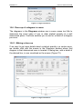
After having entered all data, ConCrete does the calculations as stated in
4.6. As a result we obtain envelope diagrams for the bending moment
and the shear forces (Figure 49). We also obtain a coexistence of the
top- and bottom reinforcement (Figure 50). This coexistence does not
mean that there is no a shiftment of the diagram of moments and no
anchorage length requested for the determination of the lengths of the
longitudinal bars. As said before, ConCrete Plus takes this automatically
into account.
49
BuildSoft n.v.
User’s manual ConCrete
Figure 49 : Diagrams - example 3
Figure 50 : Reinforcement sketch - example 3
5.3. Adding and removing load types
5.3.1. Modify directly
Click on the number of load types in the "Structure and loads"-window
and enter a new value. Modification is possible as long as there is no
load entered yet, or once the whole input of data is ready. When the
number of load types is lower than before, the latest load types are
removed; when the number is higher, additional load types are added
with all values equal to 0.
50
BuildSoft n.v.
User’s manual ConCrete
5.3.2. Modify with right mouse button
A popup-menu shows the possibilities:
Figure 51 : Popup menu – loadtypes
It is recommended to verify the load and combination factors after
changing the load types (see 4.6).
51
BuildSoft n.v.
User’s manual ConCrete
Chapter 6 An entire project of beams
52
BuildSoft n.v.
User’s manual ConCrete
6.1. Introduction
So far we have learned how to calculate a beam with ConCrete. In
chapter 3 we noticed (3.1) that when entering a new beam, the previous
entered beam is placed in the Project list-window. In this chapter we will
learn more about the structure and the use of this project list.
Figure 52 : Project list
The list is constructed as a tree. The main items are the classes, the
subitems are the elements. Currently, only one element is calculated.
The second bar has yet to be defined. Both elements are in the first
class. The date that the element was last opened is mentioned behind its
name. Moreover, the most recent date is listed next to the header of the
window itself.
The name of the active element has a grey background colour, to
distinguish this element from the other ones.
Three icons accompany the code of the element:
The first icon indicates what kind of element was introduced:
beam
slab
hollow core slab [ only with the hollow core slab module]
The second icon indicates if the element is calculated and / or its
dimensions are enough:
not calculated yet
calculated but section is insufficient;
calculated and section is sufficient;
The third icon indicates whether or not the element is calculated and
drawn with the aid of ConCrete Plus:
not drawn yet;
drawn;
53
BuildSoft n.v.
User’s manual ConCrete
Suppose that we have a project consisting of three blocks A, B and C
each containing a basement, a ground floor and ten standard floors. If
we consider all the beams of this project we can easily get a hundred
different beams.
We can however divide the beams in groups. We can e.g. consider
groups according to the block or the floor. We call such a group a class.
We can define up to 20 classes in ConCrete each consisting of a
maximum of 100 beams (and/or slabs).
The elements are automatically ranged according to their name (order:
ABC…XYZabc…xyz012…789). The name of a class is limited to 256
characters.
6.2. Defining classes
6.2.1. Choosing classes
We will distribute the beams out of the example described in 6.1 over the
following classes:
KA :
GA :
TA :
KB :
GB :
TB :
KC :
GC :
TC :
all the elements of the basement of block A
all the elements of the ground floor of block A
all the elements of the standard floor of block A
all the elements of the basement of block B
all the elements of the ground floor of block B
all the elements of the standard floor of block B
all the elements of the basement of block C
all the elements of the ground floor of block C
all the elements of the standard floor of block C
6.2.2. Input classes
We define the classes in ConCrete as follows : we select the last
command "List of classes…" in the Edit menu. The dialog box of Figure
53 is now visualised on the screen.
54
BuildSoft n.v.
User’s manual ConCrete
Figure 53 : Editing the list of classes
The names of the 20 classes are in a cadre (for the moment all blank).
The meaning of the buttons "OK", "Store" and "Retrieve" at the bottom
of the dialog box is the same as in 4.1.
By typing the word "KA" in the cadre right on top, the button "Add" can
be selected. After clicking this button the name "KA" is added in the class
list.
In a new project, where no elements have been entered, "KA" will be
situated on the first line.
It is also possible to rename a selected class from the list. Just click the
button "Rename" after selecting instead of the "Insert". Note that the
original name of the class (the name that the class was when opening
the dialog) in the box under "Original Name" is written. This may include
the elements listed in the box under "Elements".
Now enter the other classes (Figure 54).
55
BuildSoft n.v.
User’s manual ConCrete
Figure 54: Editing the list of classes
The button "Remove" can only be selected when a certain class is
selected in the list. With this button not only the name of the class is
cleared out of the list but also all the elements (beams and/or slabs) that
the class possibly contains.
6.2.3. Project list
After confirming the set classes, the Project list-window is visualised as
in Figure 55.
Figure 55: Project list – inserted classes
The list under "Class 1" contains the elements already entered.
Whether a class consist elements or not, is indicated by the mark in front
of the class name. If there is a sign ('+' or '-'), then the class consists at
least one element. Clicking the '+' will show all elements of that class,
56
BuildSoft n.v.
User’s manual ConCrete
the ‘+’ becomes a ‘-‘. Clicking the '-' hides the elements of the class.
There is one exception: if the active element (the element currently
shown in the window) is in the class.
If all elements should or shouldn’t be visible, you can use the right
mouse button (Figure 56).
Figure 56: Pop-up menu – project list
6.3. Allocating an element to a certain class
When you create a new element, this will automatically be put in the
selected class. If there are no classes defined, a standard class “class 1”
will be automatically created and selected.
You can move an element from one class to another (see 6.5).
6.4. Getting an element out of a certain class
Are the elements belonging to the class not visible, double click then first
on the class name or click on the ‘+’sign at the left.
To show and possibly modify the beam, we have two possible methods.
First select the beam in the list and than use the command "Element" "Edit" or click on the icon
, or just double click the beam in the list.
The selected beam is shown in the Structure and loads window, the
Diagrams window and the Reinforcement sketch window.
6.5. Moving an element to another class
To move an element to another class, just select the element in the list
and drag it to another class. In other words : select it with the mouse,
keep the mouse button pressed, move the mousse to another class and
release the mouse button.
57
BuildSoft n.v.
User’s manual ConCrete
6.6. Duplicating an element
Suppose that we have to calculate two elements which are nearly
identical. In that case we could first calculate the first element, and then
afterwards make a copy of it and modify this copy in order to obtain the
second element. We can do so in ConCrete in a very easy way.
We first enter the first element and add it to the desired class as
described in 6.3. Afterwards we select this element in the Project listwindow. We then select the fourth command "Duplicate" in the Element
menu or click on the icon
. The selected beam is visualised in the
windows "Structure and loads", "Diagrams" and "Reinforcement
sketch"; nevertheless it is still present in the Project list-window. In fact
we made an autonomous copy of the beam. This copy does not differ in
any way from the traditionally entered beam. This means that we can
make arbitrary modifications without influencing the first beam.
It is obvious that the time of duplicating the beam can be chosen freely :
immediately after entering the beam or later.
In 6.9 is explained how elements can be copied from one project to
another or from ConCrete to ConCrete Plus (and vice versa).
6.7. Deleting an element
To delete an element, we first select it in the Project list-window. We
then select the fifth command "Remove" in the Element menu or click on
the button
. The element is now cleared out of the class.
6.8. Copying elements between projects
To copy an element from one project to another, first get the element as
described in 8.3 and select then the “Copy” command in the “Edit”
menu. Then, open the project to which you want to copy it. Select there
the desired class and click then on the “Paste” command in the “Edit”
menu.
58
BuildSoft n.v.
User’s manual ConCrete
Chapter 7 Special elements
7. Speciale liggers
59
BuildSoft n.v.
User’s manual ConCrete
7.1. T-, I-, L- en Z-beams
With concrete, it is not only to calculate rectangular cross-sections, but
also T, I, L and Z-sections, and they may vary by zone. In case a beam
with constant section, it can be entered in the "Structure en Loads
window” with the mouse clicking in the top right rectangle (Figure 57).
This rectangle is the outline of the beam cross section.
Figure 57 : Details cross section dimensions
In case of a beam with variable sections, the section can also be added
per zone by clicking on the section sketch in "z_._" of the changing area
(z2.1 in Figure 58), again the dialog Figure 57 appears, but only valid for
the one zone.
7. Speciale liggers
60
BuildSoft n.v.
User’s manual ConCrete
Figure 58 : Structure en loads window – variable sections
In this dialog box the dimensions of the flanges can be adapted.
Four flanges are possible: two upper flanges and two bottom flanges,
one each left and right flange. The width of the flanges (the dimensions
a, b, c and d) can be both a positive and a negative value, negative
values are used to cut a rectangle from the web of the beam (a "bite"
from the web, Figure 59), positive values indicate a flange on the body
(Figure 60). The flange thickness (the dimensions e, f, g and h) have
always positive values (or zero).
Note that the width, height and height 1° phase (se e 7.3) can be
changed.
Figure 59 : ‘Negative’ flange
7. Speciale liggers
Figure 60 : ‘Positive’ flange
61
BuildSoft n.v.
User’s manual ConCrete
As already noted in 4.3, in the dialog box “Parameters of concrete” you
can indicated whether the weight of the flanges will be taken into account
or not.
Figure 61 : Reinforcement sketch – detail upperflange
If in the dialog box for the parameters of the reinforcing steel (Figure 37)
the option to display the transverse reinforcement in the flanges is
checked, you will see the "Reinforcement Sketch" dialog example from
above.
As for the transverse reinforcement in the body, there is a dimension line
with the above circled letter "a", "b" and below the respective figures, all
in italics. The circled letters are again referring to the information on the
right, the numbers below are the distances over which these zones are
valid. The right information includes the number of required reinforcing
steel mm2 (perpendicular to the plane of the drawing) per m length of the
beam. Negative values give an indication of the amount of reserve. The
designation of the reserve can sometimes be important: the standard
requires only a weighted average of the distance between a zero point
and a time limit. ConCrete, however, a more precise indication: areas
where the moment increases faster, get more transverse reinforcement
allocation than areas where less time is rapidly increasing. It is entirely
possible that ConCrete indicates that a certain zone no transverse
reinforcement is required (reserve) and in the zone next to it, while the
averaging according to the standard no transverse reinforcement is
required, hence the program indicates how much the reserve, so we
these values can optionally averaging over all time zones located
between zero and maximum. In case of unequal left and right flange, the
sheer reinforcement ConCrete proposes is valid for both flanges.
7. Speciale liggers
62
BuildSoft n.v.
User’s manual ConCrete
7.2. Beams on an elastic foundation
In previous examples the beams were calculated with only a few
supports (solid or elastic). However, if a beam resting on land must be
calculated, the discrete points will not simulate the continued support.
Such beams are calculated classically known as beams on elastic
foundation. The resisting character of the foundation (ground) is
determined by giving the elastic constant ݇.
ConCrete goes a lot further than simply calculating a beam on elastic
foundation. In ConCrete, it is even possible to give for each zone a
different elastic constant k, and on the other hand, you can add discrete
supports (fixed or elastic and/or fixed or elastic restraint to rotation). The
importance to have a different elastic constant per zone is shown in the
following problems:
- A beam which is posed on a homogenous ground, except that the
ground is crossed by a little brook;
- a beam supported by a number of concrete columns and by a large
wall in bricks;
In the first example, the presence of the brook can be incorporated by a
lower value (or even a zero value) of the elastic constant. In the second
example, the concrete columns can be entered as normal supports
(elastic or fixed), while the large wall can be simulated by zone with a
large elastic constant. In both examples, it would be very hard to obtain
an even adequate result, if we could only calculate beams supported by
either only discrete supports or a unique elastic foundation over the
whole length.
Click in the second pallet on the forth icon (Figure 4, Figure 62) to be
able to enter elastic foundations.
Figure 62 : Pallet 2 – Elastic foundation
7. Speciale liggers
63
BuildSoft n.v.
User’s manual ConCrete
In the "Structure and loads"-windows an extra line, proceeded with
"k(N/cm3)" (Figure 63), is added under the line with the indication of the
different zones. On this line you can enter the value of the elastic
constant in the zone. The elastic constant gives the relation between
the settlement and the reaction of the foundation:
with
݇ = )ݔ(ݍ. )ݔ(ݒ
ݍ
݇
ݒ
the reaction of the foundation (force / surface)
the elastic constant
the vertical displacement (settlement)
Figure 63 : Structure and loads window – List of units
In lack of more accurate data, the value of the elastic constant ݇ can be
determined as follows:
• for clayish grounds:
݇=
with
ݍ
ܾ
݈
0.5 ∙
ݍ
∙ (݈ + 0.5 ∙ ܾ)
ܾ
1.5݈
compressive strength of the ground in N/cm2
width of the beam in m
length of the beam in m
• for sandy grounds:
ܾ + 0.3048 ଶ
݇ = ݇ଵ ∙ ൬
൰
2∙ܾ
where the value of ݇ଵ is given table 1.
sand
low packed
݇ଵ (݅݊ ܰ/ܿ݉³)
2.7 − 8.1
medium
packed
8.1 − 40
table 1: elastic constant - value for sand
7. Speciale liggers
high packed
40 − 136
64
BuildSoft n.v.
User’s manual ConCrete
Higher stated values are taken from Campus F., "Contribution à l'étude
des pièces fléchies dans le sol. Application aux pieux et palplanches",
Mémoire du Centre d'Etudes, de Recherches et d'Essais Scientifiques
du Génie Civil de l'Université de Liège, N° 39, Avr il 1972.
7.3. Beams in 2 phases
Today more and more beams are partially precast. Once they are placed
at their position, a second phase is casted in which the individual beams
(per span) are casted together to form a continuous beam (possibly the
are also cast together with the slabs).
In some cases, the precast beams are used to bear a part of the loads,
without the help of additional struts. Special attention should be paid at
the impositions ! The beams are prefabricated per span and will be
loaded in an isostatic way by their selfweight and e.g. also the selfweight
of the slabs posed on those beams and the selfweight of the second
phase concrete. Once the beam is completely casted and harded, the full
section is effective and the spans are completely joined to form a
hyperstatic construction (continuous beam).
In the program two phases can be taken into account. Therefore you
have to enter next things:
• Phase 1: indicate for each section till which height the section will
be casted in the first phase, in other words. this is the height of
precast section. The program indicates this height as "ho1" and
sets this height by default equal to the total height "ho". You can
change these values by clicking in the "Structure and loads"window on the value or on the cross section sketch (see 7.1) and
then change it in the dialog box.
• Phase 2: In the dialog box for the load factors (see 4.6) you
indicate which load types are acting on the precast section in the
first phase, and which on the total section (section 2nd phase).
Load types can act in both phases or only in one of them. Of
course it is possible to have load types that act only in the second
phase.
The phases are taken into account by the calculation of the
reinforcement and of the stresses in the concrete and in the
reinforcement, as explained in 4.6.
7. Speciale liggers
65
BuildSoft n.v.
User’s manual ConCrete
For the sake of completeness, we want to mention that the calculation of
the crack width and the deformation (neither uncracked nor cracked)
does not take these phases into account.
7.4 Slabs in 2 phases
ConCrete can, besides beam, can also calculate plates in reinforced
concrete.
The places are carrying in one direction and can also be executed in two
phases (Figure 64).
Figure 64 : Slab in 2 phases
7.5. Hollow core slab library
Remark: This functionality is not available in the standard version of
Concrete. Only ConCrete Master allows you to calculate hollow core
slabs.
Finally, ConCrete has the possibility to calculate hollow core slabs.
These hollow core slabs are stored in the so-called hollow core slabs
library. To do this, select the menu "Edit" command "Hollow core slabs
library". A window appears (Figure 65) which you can define and
manage the slabs.
7. Speciale liggers
66
BuildSoft n.v.
User’s manual ConCrete
Figure 65 : Hollowcore slab library
With the button "New" you can make a new hollowcore slab. A dialog
box (Figure 66) then prompts you to different dimensions. Click "OK" to
confirm the geometry data and the hollowcore slab will be placed in the
library.
Figure 66 : Hollowcore slab library
7. Speciale liggers
67
BuildSoft n.v.
User’s manual ConCrete
Chapter 8 Saving, opening and quitting
11. Overzicht van de menu's
68
BuildSoft n.v.
User’s manual ConCrete
8.1. Saving a new project
If we now wish to save the already accomplished work as a document on
the hard disk or on another saving unit, we select the fifth command
"Save as…" in the File menu or we click on the icon
. The program
suggests to save the project in a document with the same name as the
set reference code of the project (see 2.2). We can however enter an
arbitrary name if we want to. If we save the project under another name,
this new name becomes the new title of the Project list-window.
8.2. Opening an existing project
To open an existing project in ConCrete, we select the second command
"Open…" in the File menu or we click on the icon
. The Project listwindow has got the same name as the opened file. Besides all the
documents created with ConCrete we can also open documents made
with ConCrete and adapted with ConCrete Plus. If we e.g. open a project
of 10 beams which are all of them already drawn in ConCrete Plus, we
can modify the calculation of these beams or add another beam to this
project. Beams which are already drawn in ConCrete Plus and of which
the calculation is modified in ConCrete, do not however keep their
corresponding reinforcement plan. The other beams of the project keep
of course their plan.
8.3. Saving an existing project
There are two possibilities to save an existing project in ConCrete.
The first possibility consists of resaving the document under the same
name by selecting the fourth command "Save" in the File menu. This
command can only be selected when changes have been made in the
earlier saved project. When saving, all data which were joined to the
project in ConCrete Plus are also saved, with the exception of the in 8.2
discussed data. With the “Save” instruction files are always saved in
binary format (type ConCrete).
The second possibility is saving the project under another name by
selecting the fifth command "Save as…" in the File menu. This
command can be selected at any time, in contrast to the previous.
8.4. Automatical saving
In order to protect ourselves against the loss of data by a breakdown or
any other cause, we can activate the option "Save automatically" in the
11. Overzicht van de menu's
69
BuildSoft n.v.
User’s manual ConCrete
Preferences – Save automatically menu. This option is marked by a "
" – sign if its active; in the other case, the option is not marked. When the
option is activated, the program will automatically save after certain
actions.
To define after which actions the automatically save procedure should be
performed, click on the “Preferences...” command in the Preferences –
Save automatically menu. The following dialog box appears:
Figure 67 : settings for saving automatically
Besides the fact that you can decide when a saving procedure should be
performed, you can also decide to keep a number of back-up files. Each
time a save action is performed, the previous version of the file is kept.
The number of back-up files that should be kept, can be indicated in the
tab “Preferences saving” :
11. Overzicht van de menu's
70
BuildSoft n.v.
User’s manual ConCrete
Figure 68 : Settings for back-up
Higher stated protection is relative. You can always make back-ups of
the entered project manually.
8.5. Closing a project
To close a project we select the third command "Close" in the File menu.
If modifications have been made and not yet saved, the program asks us
automatically whether we want to save this project or not.
8.6. Modifying the project data
To modify project data we select the last but one command "Modify…" in
the File menu. The dialog box of Figure 2 is again visualized on the
screen. We can now freely manipulate the data.
8.7. Quitting the program
To quit the program we select the last command "Quit" in the File menu.
If we are working in a project and the modifications have not yet been
saved, the program asks us automatically whether we want to save our
project or not.
11. Overzicht van de menu's
71
BuildSoft n.v.
User’s manual ConCrete
Chapter 9 Printing
11. Overzicht van de menu's
72
BuildSoft n.v.
User’s manual ConCrete
9.1. Page setup
To set the print options we select the command "Page setup" in the File
menu.
The dialog box of Figure 69 is now visualized on the screen. In this
dialog box we can select the printer and set its options as well as four
print options specific for ConCrete (Figure 69).
Figure 69 : Printoptions
When selecting the first option "Front page" a front page, with all project
data of Figure 2 mentioned in it, is proceeding the whole printing. The
following three options are used to print the content of the windows
which carry these titles. With the second option “Project values”, all
calculation parameters are printed : one page with all the standard
values and for each element the differences with those standard values.
The next 3 options serve to print or not the content of the windows that
have the same title.
9.2. Printing an entire project
To print an entire project we select the command "Print project…" in the
File menu. If there is still an element present in the windows "Structure
and loads", "Reinforcement sketch" and "Diagrams" and this element
is already completely entered, the program puts this element in the first
selected class of the Project list-window. The program then prints the
entire project, class after class and element after element. Only one
front page is printed per project (if the option is selected) and only one
page with the project values. The data of the Structure and loads
window are printed per beam, followed by the deviations of the present
values of the calculation parameters versus the file values. The data of
the Reinforcement sketch window and/or the Diagrams window are
printed according to the case. The program starts a new page for each
11. Overzicht van de menu's
73
BuildSoft n.v.
User’s manual ConCrete
beam. A new page is also started when printing the content of the
Diagrams window. The program sees to it that the content of this last
window is neatly flatted to the paper format. The reference code of the
project and the date are mentioned on each page. The number of the
element, proceeded by the name of the class, is mentioned right on top
of the pages, specific to the element.
9.3. Printing an entire class
If we wish to print all the elements of only one specific class, we select
this class in the Project list-window. Afterwards we select the command
"Print class…" in the File menu. This command works in a similar way
to that described in 8.2.
9.4. Printing of only one element
To print only one element, we have to get it from the Project list-window
and select the command "Print element…" in the File menu. This
command works analogous to 8.2.
11. Overzicht van de menu's
74
BuildSoft n.v.
User’s manual ConCrete
Chapter 10 Useful tips
11. Overzicht van de menu's
75
BuildSoft n.v.
User’s manual ConCrete
10.1. Automatical calculation after input
So far the program has always calculated the element after complete
input and after every modification. If we however duplicate a beam to
modify it, it can be disturbing that the program interrupts us after every
modification for a calculation which after all does not interest us. We can
avoid this by disactivating the third option "Calculate
"Calculate automatically"
automatically in
the Preference menu. Now the program only gives the notification "end
of the beam" after the end of every input and every modification,
modification, without
doing any calculation. If all the data have been entered and/or modified
and we finally want the beam to be calculated, we can do so by selecting
the last command "Calculate
Calculate" in the Element menu.
10.2. Sounds
ConCrete enables you to accompany the entry of data by specific sound.
Each quantity (like width, height, length off a span, value of a
concentrated force, of a distributed force, and so on) has a specific
sound which can serve for quick entry and modification of the data. If we
activate the fifth option "Sounds"
"
in the Preferences menu
men (= marked
with a " "), a specific sound can be heard for each question that appears
in the entry beam. Also when selecting the already entered data in the
Structure and loads window the question is accompanied by a sound. In
the other case, the entry and modification is done purely on a visual
basis by a question in the entry beam.
10.3. Connections with ConCrete
Con
Plus
The connections between ConCrete and ConCrete Plus are situated on
four levels.
First of all,, the format of the files is identical for ConCrete and ConCrete
Plus. This makes it possible to complete a project, made in ConCrete,
with ConCrete Plus, and then afterwards extend it with ConCrete, to step
over again to ConCrete Plus.
(see 7.2).
Secondly ConCrete offers the possibility to transmit a message to
ConCrete Plus. This can be very important when the person who
calculated the project with ConCrete is not the same as the one who will
draw it with ConCrete Plus. We can enter such a message by clicking in
the text balloon left at the bottom in the Structure and loads window. A
dialog box, in which we can enter the desired message, is now visualised
on the screen (Figure 70).
70). When printing this beam, the message will be
printed along with the entry data. When this beam is opened in ConCrete
11. Overzicht van de menu's
76
BuildSoft n.v.
User’s manual ConCrete
Plus, a dialog box with this message automatically appears on the
screen.
Thirdly, we can indicate in ConCrete the maximum tolerated variation in
the dimensions between the calculation in ConCrete and the drawing in
ConCrete Plus. If this variation is within the tolerance, there is no new
calculation of the beam required and the calculated values are applied
for drawing the beam. Setting these tolerances is done by selecting the
last command "Tolerances…" in the Preferences menu. The dialog box
of Figure 71 is now visualised on the screen.
Figure 70 : Note
Figure 71 : Tolerances
This tolerance is not applied on the width of the supports. The width of
the support for that matter is not indicated in ConCrete but in ConCrete
Plus. The tolerance of the span lengths is valid for the centre-to-centre
distance of the supports.
11. Overzicht van de menu's
77
BuildSoft n.v.
User’s manual ConCrete
Finally, we can exchange elements between ConCrete and ConCrete
Plkus by the commands "Edit" "Copy" and "Edit" "Paste" (see also 6.9).
ConCrete Plus exists as a separate program or can be integrated as a
DLL in ConCrete. If you use the separate program, then you switch from
ConCrete to ConCrete Plus by the command “File – Transfert ConCrete
Plus”. Of course, it is also possible to simply open a ConCrete file within
ConCrete Plus”.
If ConCrete Plus integrated in Concrete, then you open the module by
the button
in the icon bar. We refer to the ConCrete Plus user’s
manual for more information over the functionalities of van ConCrete
Plus.
10.4. Showing more diagrams or limit states
So far the Diagrams window only contained the diagrams of the bending
moments and of the shear forces in U.L.S, the deflection under a Q.P.
limit state and the reinforcement.
Select in the menu "Preferences" the first command "Show diagrams" or
click on this
button to show more or less diagrams in this window. A
dialog box (Figure 73) will appear on the screen. In this window you can
check the diagrams that should appear in the window ‘Diagrams’. The
height scale of the graphs is always determined such that all desired
graphs nicely distributed evenly across the window.
The diagrams of the rotation angles and of the deflections are calculated
according to the linear-elastic method. If we select the option "with
cracked sections", the program does not only calculate the elastic
deflection, but also a more sophisticated deflection which takes the
cracked state into account. This last one is represented in red in the
Diagrams window.
The deflection in the serviceability limit state under the quasi-permanent
combinations should be limited to 1/250 of the span length, where the
deflection can cause damage to other elements even 1/500. Is the option
"after creep " designated, then the creep will be charges in the elastic
analysis and in the calculation of the cracked state.
11. Overzicht van de menu's
78
BuildSoft n.v.
User’s manual ConCrete
Figure 72 : Show diagrams
Since there are no rod diameters chosen yet, the calculation of crack
width is only based on the theoretically required reinforcement sections.
The crack width depends on the diameter and number of the rods, such
that a calculation of crack width in itself can not be approached from
theoretical reinforcement sections. The limitation of crack width in
Concrete leads to a somewhat reverse calculation: ConCrete calculates
how many bars at least should be placed so that the maximum allowable
crack width is not exceeded, assuming all the very minimum
reinforcement section is placed and that all bars will have the same
diameter.
So far the "Structure and loads" window contained the vertical reactions
and, should this be the case, moment reactions in the ultimate limit state
(ULS). Should the reactions in the serviceability limit state rare
combinations (ZC) or the serviceability limit state quasi-permanent
combinations (Q.-P.) be visible, then select in the menu "Preferences"
the second command "Show results " or click
the following dialog:
11. Overzicht van de menu's
. The screen displays
79
BuildSoft n.v.
User’s manual ConCrete
Figure 73 : Show results
In this window you can indicate of which limit state the reaction should
deplayed in the ‘Structure and loads’-Window. Furthermore, you can also
• indicate that the ‘Structure and loads’-window should show the
maximum required upper and lower reinforcement per zone
• show the maximum (in cracked condition computed) deflection
among the rare-permanent and / or quasi-permanent combination
• show how the deflections relate to the span length
• show the maximum increase of the deflections under the rare
combinations compared to the deflections under the quasipermanent combination (possibly also in relation to the span
length).
10.5. Sign conventions for moment and shear force
Not everybody uses the same sign convention for the bending moment
M and the shear force V. We can modify or overview this sign convention
by selecting the third command "Sign" in the Preferences menu. We
can specify our usual sign convention in the thus created dialog box
(Figure 74).
11. Overzicht van de menu's
80
BuildSoft n.v.
User’s manual ConCrete
Figure 74 : Sign conventions
10.6. Close-up of a diagram in a zone
The diagrams in the Diagrams window are in some cases too little to
determine the exact value of one or other statical quantity at a well
determined place. ConCrete enables you to ask for a detail of a diagram
per zone.
10.6.1. Making a close-up
If we want to get more details about a statical quantity in a certain zone,
we double click with the mouse in the Diagrams window where that
diagram in that determined zone is located. A dialog box, with a detail of
the desired line, is now visualised on the screen (Figure 75).
Figure 75 : Sign conventions
11. Overzicht van de menu's
81
BuildSoft n.v.
User’s manual ConCrete
In the lowest half of this dialog box we see the requested detail of the
diagram in the considered zone with indication of the characteristic
values like the extremes and the O-points. In the upper half we see the
minimum and maximum values of the shear force, the bending moment,
diagram of rotation angles and deflection in one well determined point.
The values for the deflection are the elastic calculated ones. Right on top
there is a button with which we can print the content of this dialog box.
10.6.2. Changing to another diagram
Use the mouse in the menu next to the "close-up of chart": the desired
diagram.
10.6.3. Withdrawing values in isolated points
The minimum and maximum values of all static quantities at a specific
point can be requested by entering the x-value (abscissa) of that point in
the edit box. Only abscissa values within the zone taken into close-up,
give results. The abscissa value is determined from the left support of
the span to which that zone (and also that point) belongs.
In Figure 75 the values are shown in the point that is situated at 2 m from
the left support of the first span of ‘beam 3’.
In the diagram, the abscessa value is indicated by two small squares,
respectively the minimum and maximum values, connected by a vertical
line.
Instead of typing the abscessa value with the keyboard, you can also use
the mouse to indicate the desired location in the close-up chart. The
abscessa value is automatically put in the edit box. Hold the mouse
button down to see the position continuously changing.
10.7. Use of the "Edit"-menu
One of the most known functions of Windows and other GUI's is the
mutual use of the commands "Undo", "Cut", "Copy", "Paste" and
"Clear". While the bar is not fully implemented, these functions can not
be used. We can e.g. use these functions to calculate determined loads
with the help of a calculation program and copy these values to the edit
box of the input bar.
Once the bar is completely entered, we can use the commands "Copy"
and "Paste", to copy elements from a ConCrete-file into another
ConCrete-file or to a file in Concrete Plus and vice versa (see also 6.8).
11. Overzicht van de menu's
82
BuildSoft n.v.
User’s manual ConCrete
10.8. Calculation method
In ConCrete, the organic calculations are done by using the method of
limit states. The calculation can be carried out according to different
standards. The desired standard is set by selecting "Preferences"
command "Calculation Method" option. In the dialog box (Figure 76)
you can indicate your choice.
Figure 76 : Sign conventions
10.9. Verification calculation
In ConCrete the calculation of the cracked deformation and the crack
width is done by using the theoretically required reinforcement sections.
The results of this calculation gives a good indication of the expected
results of a calculation that takes into account the actual planned
reinforcement. In some cases the user is not satisfied with the "rough"
calculation based on the theoretical reinforcement sections.
Once the beam is drawn in Concrete Plus, you can recalculate the
structure in ConCrete, but taking into account the actual planned
reinforcement. This verification calculation involves the calculation of the
cracked bending under rare combinations and under the quasipermanent combination, and the crack width in the quasi-permanent
combination. If the effects of creep were taken into account in the initial
"rough" calculation, then they will also be used in the verification
calculation.
It goes without saying that any change in the calculation parameters,
except whether or not taking creep into account, will influence the
reinforcement choice and therefore the verification calculation will be
destroyed.
11. Overzicht van de menu's
83
BuildSoft n.v.
User’s manual ConCrete
To execute the verification calculation, select with the mouse in the
menu "Element" the command "Check". The resulting diagrams for the
cracked deflection and crack width are presented in the "Control"window. You can access this window through “Window – Control”
command or with the
button.
10.10. Saving and retrieving preferences in files
In chapter 4 we explained how to change, set as default and retrieve the
various parameters used in the calculation.
Every time the program is restarted, these default values are loaded.
Each new set of the default values, will erase the previous ones. It may
however be useful to have different sets of default values in place: for
example, to distinguish the calculation of beams from slabs,
prefabricated from in-situ beams, projects with or without external
control, foreign from domestic projects, etc.
Therefore ConCrete has the ability to store the default values in a
separated file with the comment “Preferences" "Save Defaults". In the
dialog box that appears on the screen, you can identify where and under
what name the default values should be saved. To use previously saved
default values, select the command "Preferences" "Open default
values ". The default values read, stay the default values when
ConCrete is restarted.
10.11. Adapting ConCrete’s environment
You can customize your work environment with the concept of "dockable
toolbars". This means that you can drag the icons over the screen, and
place them wherever you want. Moreover, you can include the palettes
"Input Data" and "Calculation Parameters" into the toolbar. To do so
drag the palettes on the screen or you double-click on the pallets. If you
no longer want these icons on the screen, you can simply hide then by
closing the palettes. You can recall them at any time through the
command "Window - Toolbars".
11. Overzicht van de menu's
84
BuildSoft n.v.
User’s manual ConCrete
Figure 77 : Show or hide toolbars
Choosing the option “Restore Toolbars ", will activate the original
configuration again.
In addition, the project list can also be given a permanent place in the
Concrete user interface. By double-clicking the title bar of the “Project
List”-window or by dragging the window, you can put it e.g. on the left.
11. Overzicht van de menu's
85
BuildSoft n.v.
User’s manual ConCrete
Figure 78 : ConCrete’s environment
Note: Your personal settings are automatically saved and will be applied
the next time you reboot ConCrete.
11. Overzicht van de menu's
86
BuildSoft n.v.
User’s manual ConCrete
Chapter 11 Overview of the menu's
11. Overzicht van de menu's
87
BuildSoft n.v.
User’s manual ConCrete
11.1. "File"-menu
"New…"
"Open…"
"Close"
create a new project (see 2.2)
open an existing file (see 7.2)
close the actual project (see 7.5)
"Save"
resave the current project (see 7.1 and
7.3)
save the current project (see 7.3)
backup and save automatically (zie ook
8.4)
"Save as…"
"Preferences saving…"
"Page Setup…"
"Printoptions…"
"Print -> project..."
"Print -> class…"
"Print -> element…"
printer and page settings (see 8.1)
set the print options (see 8.1)
print the current project (see 8.2)
print the selected class (see 8.3)
print the selected element (see 8.3)
"Modify…"
"Transfer ConCrete Plus" :
change the file data (see 7.6)
make ConCrete Plus link (see 10.3)
"Quit"
quit the program (see 7.7)
11.2. "Edit"-menu
"Undo"
Windows functionality (see 9.7)
"Cut"
"Copy"
"Paste"
"Clear"
Windows functionality (see 9.7)
Windows functionality (see 9.7)
Windows functionality (see 9.7)
Windows functionality (see 9.7)
"List of classes…"
"Hollowcore slab library...”
define the classes (see 6.2)
Viewing the hollowcore slab library (see
7.5)
11.3. "Element"-menu
11. Overzicht van de menu's
88
BuildSoft n.v.
User’s manual ConCrete
"New beam"
"New slab"
"New hollowcore slab"
enter a new beam (see 2.3)
enter a new beam (identical)
Enter a new hollowcore slab (identical)
"Modify"
"Duplicate"
"Remove"
modify the selected element (see 6.4)
duplicate the selected element (see 6.6)
remove the selected element (see 6.7)
"Calculate"
"Check"
"Redraw"
calculate the current element (see 9.1)
check the current element (see 10.9)
redraw projectlist
11.4. "Window"-menu
"Structure and loads"
"Diagrams"
"Reinforcement sketch"
"Check"
bring this window to front (see 2.3 and
2.4.1)
identical (see 2.3 and 2.4.2)
identical (see 2.3 and 2.4.2)
identical (see 10.9)
"Cascade windows"
cascade windows
"Input panel"
"Project list"
pop up input panel
bring the project list window to front (see
2.2 and 2.3)
customize ConCrete workspace
(see 10.11)
"Toolbars"
11.5. "Preferences"-menu
11. Overzicht van de menu's
89
BuildSoft n.v.
"Show diagrams..."
"Show results…"
"Signs..."
User’s manual ConCrete
show different diagrams (see 9.4)
show different results in several limite
states,
reinforcement,
cracked
deformation (see 9.4)
set sign convention for M and V (see 9.5)
"Calculate automatically"
"Save automatically"
immediate calculation after entry (see 9.1)
save after every five new elements (see
7.4)
"Sounds"
specific sounds when entering and
changing see (9.2)
"Tolerances…"
"Calculation method…"
measurement deviations of ConCrete vs.
ConCrete Plus (see 9.3)
set calculation code (see 10.8)
"Language"
choose language
"Load settings…"
Loads a set of saved parameters for
calculation and sets them as default (see
10.10)
Saves the parameters for calculation (see
10.10)
restore standard settings
"Save settings…"
"General settings…"
11.6. "Help"-menu
"Manual"
"Mail to BuildSoft"
"Network... "
"About ConCrete…"
allows a dynamic use of the manual to the
screen
automatically opens the default mail
program and enters the email address
look for network licence dongle
information about ConCrete