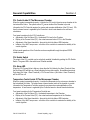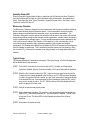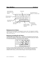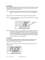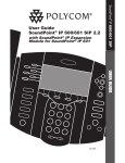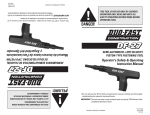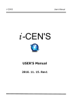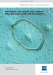
1
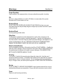
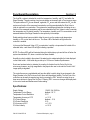
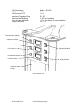
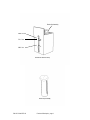
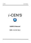
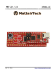
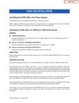
LiveCell 3 Users Guide Table of Contents Introduction Warnings Functional Description General Capabilities Installation and Setup User Interface Section 1 Section 2 Section 3 Section 4 Section 5 Section 6 Introduction Section 1 The Neue Biosciences’ LiveCell 3 system is designed to provide users with a simple to use yet precisely controlled environment for the culturing of cells on a microscope stage. You can adjust and precisely control the temperature, humidity and CO 2 level inside of the modest sized microscope stage chamber. Accurate and precise closed loop control of CO2 eliminates the need for expensive pre-mixed CO2 gas or the inconsistencies of flow rate mixing of gases to enrich the environment to the desired level. Absolute control of the temperature and humidity levels in the chamber enables longer time lapse observations without worrying about evaporative loss or possibilities of condensation on the optical surfaces. You can just simply adjust the temperature, humidity, or CO2 Set Points through a simple front panel interface, enable the controllers, and the control unit does the rest. The microscope stage chamber is large enough to allow the user to view cells in larger culture flasks as well as slides and plates without suffering the poor regulation, the need for a separate CO2 enrichment chamber, and leaks common to the larger whole microscope chambers. The LiveCell 3 was designed to be a closed environmental control system in order to minimize the CO2 usage and therefore the leakage to the outside working environment ( this is particularly critical in small poorly ventilated labs ). OCCUPATIONAL LIMITS FOR AMBIENT C02 IS 5000 PPM. THE LIVECELL 3SYSTEM HAS BEEN DESIGNED TO MINIMIZE CO2 LEAKAGE DURING NORMAL AND EVEN ABNORMAL CONDITIONS, HOWEVER THE USER SHOULD INSTALL A CO2 MONITOR AND ALARM IN ANY AREA WHERE CO2 COULD BUILD UP TO DANGEROUS LEVELS. The temperature is adjustable and controlled from ambient to 50 0.1 C (The system only has heating capability), humidity is adjustable and controlled from ambient to condensation within 1%, and the C02 level can be adjusted and controlled from ambient to 10 0.1%. This document is intended to be a comprehensive guide on the installation, use, troubleshooting, and maintenance of the LiveCell 3. P/N 05-17-0000 REV 02 Introduction, page 1 Warnings Section 2 Proper Operation Proper operation of this equipment relies on the user reading this user guide in its entirety. CO2 Use only in a well ventilated area or install a CO2 Monitor to ensure safety of the operator. Disconnect the CO2 source when not in use. Electrical Shock DO NOT OPEN THE CONTROLLER HOUSING FOR ANY REASON as there are no user serviceable parts inside and potentially dangerous voltages may be present even with the power cord disconnected. Electrical Shock Use only properly grounded outlets. Other Uses The Equipment is intended to be strictly dedicated to the control of the environment on the microscope stage that the chamber is specifically designed for. Operation of the Equipment for any other purpose or microscope stage may result in permanent damage to the Equipment or may create a harmful situation for the user. THE INSTALLATION ON ANY OTHER DEVICE MAY DAMAGE THE EQUIPMENT, INJURE THE USER, AND VOID ALL WARRANTIES. Water for Humidification Use room temperature tap water to fill the bottle to the fill line, DO NOT OVERFILL . Overfilling the bottle may result in damage to internal components of the system. DO NOT USE DI WATER since the system senses the resistance of the water to prevent running dry. THE HUMIDIFICATION BOTTLE MUST BE EMPTIED WHEN NOT IN USE. Cleaning The LiveCell 3 Controller Unit may only be wiped down with a damp cloth. Avoid the use of solvents and abrasive cleansers. The Chamber itself should never be cleaned with any ammonia based cleaners, solvents, or abrasive cleansers. Use only cleaning products recommended for Acrylic, Plexiglas, Lexan, and coated optical components. DO NOT CLEAN THE CO2 SENSOR! Service DO NOT ATTEMPT TO SERVICE THE EQUIPMENT unless otherwise instructed to do so by an authorized Neue Biosciences representative. Doing so will void the warranty or service contract. Fuses Replace only with same type and rating. P/N 05-07-0000 REV 02 Warnings, page 1 Functional Description Section 3 The LiveCell 3 system is intended to control the temperature, humidity, and CO2 level within the Stage Chamber. Thereby creating a long term incubation environment right on a microscope stage. The system utilizes CO2 from an external, regulated, CO2 source and then meters the CO2 into the system as a function of the measured concentration and the user selectable Set Point Value in order to maintain the concentration. The system also humidifies and heats the circulating air as a function of the measured temperature and the user selectable Set Point Values in order to maintain the temperature and % relative humidity. The temperature, humidity, and CO2 concentration are all measured inside of the Stage Chamber in close proximity to the sample. Enable switches have been provided to allow the user to run the system under temperature, humidity, or CO2 control alone all at once. The Green LED of the switch will light when the controller is enabled. In the event the Measured Value of CO2 concentration, humidity or temperature fall outside of the allowable limits, a red Alarm LED will light indicating a problem. NOTE: The Alarm LEDs will be illuminated during the initial startup cycle and will turn off when the system has stabilized. OR, when a controller has been disabled. Humidity is actively added to the system if the water level is maintained within the limits displayed on the bottle holder. A full bottle may provide up to 120 hours of hands off performance. Great care has been taken to minimize the coupling of vibration from the Control Unit to the microscope, however, very high magnification may require the user to relocate the Control Unit if image quality is degraded. The controllers are very sophisticated and have the ability to quickly bring the environment in the Stage Chamber to the Set Points and hold it there with tremendous stability. The Set Point of the controllers can be easily changed at any time by pressing the “SEL” button then using the up or down arrow buttons to change the Set Point. Pressing “SEL” once more changes the display back to the control mode and Measurement Value reading. Specifications: Supply Voltage Temperature Control Range Temperature Control Resolution Temperature Accuracy at 37 C CO2 Control Range CO2 Control Resolution CO2 Accuracy at 25 C CO2 Non-Linearity P/N 05-17-0000 REV 02 110VAC, 5A, 50/60 Hz Ambient - 50 C 0.1 C < 1.5 % Ambient – 10 % 0.1% < 0 .2 % < 0.5 % Functional Description, page 1 %RH Control Range %RH Control Resolution %RH Accuracy at 37 C Operational Temperature Range Operational Humidity Range Warm-up time for stabilization Storage Temperature Ambient – 85% RH 1% < 2 % 25 - 35 C 0 – 85% non-condensing < 30 min. but depends on room temperature -30 – 70 C Temperature Alarm Indicator Temperature Controller CO2 Alarm Indicator CO2 Controller Temperature Enable Sw. CO2 Enable Sw. Humidity Alarm Indicator Humidity Controller Humidity Enable Sw. Humidification Bottle Assembly LiveCell Controller Unit P/N 05-17-0000 REV 02 Functional Description, page 2 Bottle Cap Assembly “MAX” Fill Line “FILL” Line “MIN” line Humidification Bottle Assembly Bottle Cap Assembly P/N 05-17-0000 REV 02 Functional Description, page 3 Temperature Controller The control unit for the Stage Chamber temperature. Temperature Enable Switch Enables and Disables the Temperature control. Illuminated is Enabled. Temperature Alarm Indicator An LED that is illuminated any time the temperature differs from the Set Value (SV) by more than 0.5 C. CO2 Controller The control unit for the Stage Chamber CO2 concentration. CO2 Enable Switch Enables and Disables the CO2 control. Illuminated is Enabled. CO2 Alarm Indicator An LED that is illuminated any time the CO2 level differs from the Set Value (SV) by more than 0.5 %. %RH Controller The control unit for the Stage Chamber humidity. %RH Enable Switch Enables and Disables the humidity control. Illuminated is Enabled. %RH Alarm Indicator An LED that is illuminated any time the %RH differs from the Set Value (SV) by more than 5 %RH. Humidification Bottle Assembly A bottle assembly used to introduce water vapor into the system. Control Unit The integrated controller for Temperature, Humidity and CO2. P/N 05-17-0000 REV 02 Functional Description, page 4 Chamber Connector CO2 Connector Optional RS232 interface CO2 in from source Intake (from Chamber) On/Off Switch Exhaust (to Chamber) Fuses Power Entry Power Entry Provides power to the whole system. CO2 Entry Provides CO2 to the system from an externally regulated source. Fuses Two 250V, 5A fast blow fuses type GMA-5ABC. On/Off Switch Turns the unit On and Off. Intake The return path for the air handling system. This is connected to the Chamber’s “Output to Controller” connection. Exhaust The output of the air handling system that goes directly to the Chamber’s “Input from Controller”. Chamber Connector This is where the gray chamber cable connects to the Control Unit.. P/N 05-17-0000 REV 02 Functional Description, page 5 CO2 Connector NOTE: This is where the orange chamber cable connects to the Control Unit. Trying to force the incorrect cable into a connector will result in bent or broken pins on the cable. Optional RS232 This is were the RS232 cable would connect for optional serial communications with the controller. P/N 05-17-0000 REV 02 Functional Description, page 6 Out to Controller “Intake” Lens Assembly CO2 Sensor Inside CO2 Sensor Cable Temp / %RH Sensor In From Controller “Exhaust” Chamber Cable Front View of Incubation Chamber Chamber Switch Foam Seal In From Controller Connection for hose from LiveCell 3 Control Unit “Exhaust”. Out To Controller Connection for hose to LiveCell 3 Control Unit “Intake”. CO2 Sensor Sensor for CO2 level feed back to Controller. Temp and %RH Sensor Sensor for Temperature and Humidity feedback to Controller. Chamber Connector The connector for lid switch signals and temperature signal. Sensor Connector The connector to the CO2 sensor. Chamber Switch This switch disables controller outputs if the Chamber is not positioned properly. Lens Ass’y The interchangeable optical window assembly for different illumination condensers. Foam Sealing Strips Seals Chamber ato the Stage. P/N 05-17-0000 REV 02 Functional Description, page 7 General Capabilities Section 4 CO2 Control Inside Of The Microscope Chamber When the system is assembled properly, it controls the CO2 level in the microscope chamber to the last entered Set Value. The system uses a CO2 sensor inside of the Chamber to provide information the CO2 Controller requires for precise and accurate stabilization of the CO2 level. CO2 from the eternal source is regulated by the Controller in short bursts based on the self-tuned calculations. Front panel operations for the CO2 Controller are: Adjustment of the Set Value (SV) – the desired CO2 level in the Chamber. Display of the Process Value (PV) – the actual measured value of CO 2 in the Chamber. Adjustment of the Alarm thresholds – the point at which the Alarm LED illuminates. Initiation of the Self-Tune process – a function of the controller to maximize the stability of the control algorithm. All front panel operations of the Controller can be accomplished through the optional RS232 interface as well. CO2 Enable Switch The output of the CO2 controller can be selectively enabled / disabled by pushing the CO2 Enable Switch. The green LED in the switch turns ON when enabled. CO2 Alarm LED When the CO2 Process Value is higher or lower than the Set Value by the Alarm Threshold, then the Red Alarm LED will light as a visual indication that a problem exists. No audible alarm exists. Only when (Set Value - Alarm Threshold) < CO 2 Process Value < (Set Value + Alarm Threshold) will the LED turn off. Temperature Control Inside Of The Microscope Chamber When the system is assembled properly, it controls the temperature in the microscope chamber to the last entered Set Value. The system uses a thermal sensor inside of the chamber to provide information the Temperature Controller requires for precise and accurate stabilization of the temperature. A heat source is regulated by the Controller based on the self-tuned calculations. Front panel operations for the Temperature Controller are: Adjustment of the Set Value (SV) – the desired temperature in the Chamber. Display of the Process Value (PV) – the actual measured temperature in the Chamber. Adjustment of the Alarm thresholds – the point at which the Alarm LED illuminates. Initiation of the Self-Tune process – a function of the controller to maximize the stability of the control algorithm. P/N 05-17-0000 REV 02 General Capability, page 1 All front panel operations of the controller can be accomplished through the optional RS232 interface as well. Temperature Enable Switch The output of the temperature controller can be selectively enabled / disabled by pushing the Temperature Enable Switch. The green LED in the switch turns ON when enabled. Temperature Alarm LED When the temperature Process Value is higher or lower than the Set Value by the Alarm Threshold, then the Red Alarm LED will light as a visual indication that a problem exists. No audible alarm exists. Only when (Set Value - Alarm Threshold) < Temperature Process Value < (Set Value + Alarm Threshold) will the LED turn off. Over Temperature Protection In the event of a misassembled system, failure of one or more components, or improper operation, the unit has over temperature protection to keep the User from getting burned in the event of a thermal run away condition. Humidity Control Inside Of The Microscope Chamber When the system is assembled properly, it controls the humidity in the microscope chamber to the last entered Set Value. The system uses a humidity sensor inside of the chamber to provide information the Humidity Controller requires for precise and accurate stabilization of the humidity. Water vapor from the Humidification Bottle Assembly is injected into the system under regulation by the Controller based on the self-tuned calculations. IT IS IMPORTANT TO STABILIZE THE TEMPERATURE BEFORE ENABLING THE HUMIDITY SINCE %RH IS TEMPERATURE DEPENDENT. ALSO, IT IS IMPORTANT TO BRING THE HUMIDITY LEVEL UP SLOWLY TO THE POINT THAT SOME CONDENSATION IS OBSERVED EITHER ON THE LENS ASSEMBLY OR THE STAGE TOP. WHEN THIS OCCUS, ADUST THE HUMIDITY SET POINT DOWN BY 5% AND THE CONDENSATION SHOULD DISSAPEAR IN A FEW MINUTES, IF NOT ADJUST DOWN ANOTHER 5%. The humidity drops very slowly and to speed the drop in humidity, remove the hose at the Controller Intake Hub for a few seconds. Front panel operations for the Humidity Controller are: Adjustment of the Set Value (SV) – the desired humidity in the Chamber. Display of the Process Value (PV) – the actual measured humidity in the Chamber. Adjustment of the Alarm thresholds – the point at which the Alarm LED illuminates. Initiation of the Self-Tune process – a function of the controller to maximize the stability of the control algorithm. All front panel operations of the controller can be accomplished through the optional RS232 interface as well. Humidity Enable Switch The output of the humidity controller can be selectively enabled / disabled by pushing the humidity Enable Switch. The green LED in the switch turns ON when enabled. P/N 05-17-0000 REV 02 General Capability, page 2 Humidity Alarm LED When the humidity Process Value is higher or lower than the Set Value by the Alarm Threshold, then the Red Alarm LED will light as a visual indication that a problem exists. No audible alarm exists. Only when (Set Value - Alarm Threshold) < humidity Process Value < (Set Value + Alarm Threshold) will the LED turn off. Microscope Chamber The Microscope Chamber is designed to house various sizes and formats of incubation vessels as well as various working distance illumination lenses. The accommodation of various working distance lenses is accomplished with removable, drop-in, optical window assemblies. The Chamber is designed to create a uniform flow across the optical axis for even control with minimal temperature gradients throughout the Chamber and the temperature / humidity sensor is located in a region representing the average values. For high humidity applications some condensation may occur in the corners or edges of the Chamber, on the stage top, or the Lens Assembly, this is normal and primarily caused by slight temperature gradients in the chamber and ambient temperature. The Chamber has a switch that will disable the CO2 and Temperature Controllers any time the chamber is repositioned. This is intended to keep the system from over-heating or filling the room with CO2 in the event the chamber is not sitting properly on the stage while running and enabled. Typical Usage: The following description is intended as a summary of the typical usage. All of the following steps will be detailed later in this document. STEP 1: The LiveCell 3 Controller Unit is turned on with the CO2, Humidity, and Temperature Controllers Disabled. After the Controllers initialize, the Process Values will be displayed. STEP 2: Check the Set Values by pushing the “SEL” button on the front panel of each controller. To make sure the number displayed is the Set Value, the “SV” LED should be illuminated. In order to change the Set Point, use the “up” and “down” arrow key to change the display to the desired Set Point. Once the desired Set Point is displayed, push the “SEL” button once more to accept the value. The “SV” LED should turn off and the display will revert back to reading the Process Value. STEP 3: Verify all connections are properly made. STEP 4: Enable the desired controllers. For example, If only temperature control is desired then keep the CO 2, and humidity disabled, etc.. Allow the system to stabilize. This will occur in less than 30 min. The Alarm LEDs for the Enabled controllers will be off when stabilized. STEP 5: Once stable, the system is ready. P/N 05-17-0000 REV 02 General Capability, page 3 STEP 6: Shutting the system down when humidity is not enabled is a simple as turning the power off, and turning off the CO2 supply. Shutting down the system when humidification has been used involves running the system with the Humidification Bottle Assembly removed for 15 minutes or until any condensation on the chamber disappears. The bottle should be emptied when not in use, stored, or moved. P/N 05-17-0000 REV 02 General Capability, page 4 Installation and Setup Section 5 Un-Packing: The following is a list of the packaged items: 1 – LiveCell 3 Controller Unit 1 – Power Cord 1 – Gray 8-pin Mini-DIN cable 1 – Orange 8-pin sensor cable 1 – Microscope Chamber 1 – RS232 Cable (optional) 2 – 6 ft. hoses 1 – 10 ft. CO 2 1/4” line 1 – Optical Window Assembly Tube 1 – Users Guide Installation: The installation process is: STEP 1: Install the Chamber on top of the microscope stage by tilting back the microscope’s Illumination Pillar, and positioning the Chamber over the stage until it sets completely over the stage and rests on the Foam Sealing Strips. Note the click of the chamber switch as the chamber is lowered. STEP 2: The Chamber can be installed with the connectors facing to the right or the left side, but not front or back. When properly installed the Chamber will be level with the microscope stage and should not hang over any edges. Now the Illumination Pillar can be tilted back into position. STEP 3: Connect one end of the 8-pin gray mini-DIN cable to the connector labeled “Chamber” on the Chamber and the other end to the LiveCell 3 Controller Unit connector labeled “Chamber“. NOTE: Trying to force the incorrect cable into a connector will result in bent or broken pins on the cable. STEP 4: Slide one end of a hose OVER the Chamber connection hub labeled “IN FROM CONTROL UNIT’S EXHAUST” and the other end INTO the LiveCell 3 Controller Unit hub labeled “Exhaust”. STEP 5: Slide one end of the other hose OVER the Chamber connection labeled “OUT TO CONTROL UNIT INTAKE” and the other end INTO the LiveCell 3 Controller Unit hub labeled “Intake”. P/N 05-17-0000 REV 02 Installation, page 1 NOTE: The hose connections should slide either into or over the hubs fully to prevent the hose from accidentally disconnecting. STEP 6: Connect the CO2 source to the LiveCell 3 control unit and adjust the regulator to 10 psi. Do not exceed 10 psi. NOTE: When not in use the CO2 source should be disconnected and turned off. STEP 7: If humidity is to be controlled, remove the Humidification Bottle Assembly by pushing in on the humidification unit to release, then removing. Once removed, the cap can be removed to add water to the bottle. Add ROOM TEMPERATURE TAP WATER to the bottle’s “FILL” line. Once the cap assembly is re-installed the water level will raise but should not be above the “MAX” fill line. During operation make sure the level is within acceptable limits as displayed on the label. DO NOT USE D.I. WATER. D.I. water will disable the automatic shutdown of the humidification unit in the event of running out of water. NOTE: Do not attempt to loosen the screws on the cap. NOTE: Do not overfill the bottle: damage to the internal components may result. P/N 05-17-0000 REV 02 Installation, page 2 User Interface Section 6 LED that indicates the SET VALUE is currently displayed Display digits Label indicates the type of controller, i.e. C, %CO 2, or %RH LED indicates that the controller is active LED indicates alarm condition exists Select button used to select menu options Up button to navigate through menus and to modify data Down button to navigate through menus and to modify data Displaying Current Values: Upon power up the controllers will display the current values for temperature, humidity, and C02 and the “SV” LED will not be illuminated. As the system stabilizes, the current values can be observed. Displaying and Setting the Set Values: The previous Set Values are held in memory. To change the Set Values the User must power the unit up, wait for the displays to display actual numbers, then press the “SEL” button once. Now the “SV” LED will illuminate and the current Set Value will be displayed. Use the Up and Down buttons to change the Set Value. Once the Set Value is correct, the User only needs to press the “SEL” button once to accept. Three seconds later the value will be accepted, stored in memory, and the controller will begin to control the system to that value. P/N 05-17-0000 REV 02 Basic User Interface, page 1 Auto-tuning: When the system is assembled properly there is no need to run the Auto-Tune feature. However if the system becomes unstable due to changes in the microscope stage or Chamber, the system might require tuning for optimal performance. STEP 1: Assemble the unit properly, power up the unit and make sure the CO 2 supply is on and regulator is properly adjusted, and that the water level is correct in the Humidification unit. STEP 2: Enable the controllers with the Enable switches and allow the system to stabilize. STEP 3: From the Front panel of each controller push the “SEL” button and hold it for ~3 seconds. or until the display looks like: Auto-Tune LED indicator STEP 4: Pushing the “SEL” button once more will display the value of the Auto-Tune value. When the system is normally operating the value is 0. In order to command the unit to self tune, the 0 must be changed to a 1 by using the “Up Arrow”. Once the display shows a 1, the “SEL” button should be held for three seconds until the display returns to the Set Value. One more push of the “SEL” button will display the current reading. During the Auto-Tune process, the Auto-Tune LED will blink. Calibration: In the event the system requires calibration, the displayed value can be offset using the PVOF menu. Before entering the adjustment menu, record the difference between the desired measurement and the displayed measurement. STEP 1: This menu is accessed by holding the “SEL” button down for ~6 seconds or until the display looks like: P/N 05-17-0000 REV 02 Basic User Interface, page 2 STEP 2: Press the SEL button once to transition into the adjustment menu, then using the UP and DOWN buttons, enter the desired adjustment: STEP 3: Press the SEL button and hold for ~3 seconds or until the Set Value is displayed. The offset is now stored and will be used. P/N 05-17-0000 REV 02 Basic User Interface, page 3 RS232 Interface (special option p/n 40302) Using HyperTerminal software (located in programs/ accessories/ communications in a Windows-based operating system), the following instructions allow for the monitoring and setting of temperature and CO2 data: Open HyperTerminal and start a New Connection from File pull down menu Choose following settings: Com1 port (serial port), 9600 bits/second, 8 data bits, None Parity and 2 stop bits. Flow control to Hardware. ANSIW format. Confirm connection of RS232 cable from back of LiveCell to PC Serial port Type <enter> to view the version of the firmware “LiveCell Version: 2” There are six basic commands: Type C?<enter> to request the current set point and actual data for CO2% Type C= 5.0<enter> to change the set point to 5.0% CO2 (can set up to 10.0%) Type T?<enter> to request the current set point and actual data for Temperature Type T= 37.0<enter> to change the set point to 37.0 deg C (can set up to 50.0C) For service or technical support contact: Pathology Devices P.O. Box 1093 Westminster, MD 21158 Phone: 410.876.5004 Fax: 410.876.6006 email: [email protected]