1
DRAFT- FOR OFFICE USE ONLY
PRINT DATE:05/22/13
PRINT TIME: 15:25
REQUIREMENT CONTRACT
PIN: 8571300471
SPECIAL INSTRUCTION TO BIDDERS
CONTRACT SPECIFIC TERMS AND CONDITIONS
CITY OF NEW YORK
DEPARTMENT OF CITYWIDE ADMINISTRATIVE SERVICES
DIVISION OF MUNICIPAL SUPPLY SERVICES
MUNICIPAL BUILDING, NEW YORK, NY 10007
--------------------------------------BID NUMBER: 1300471.
BID TITLE: AMBULANCE, TYPE 1 - FDNY
-------------------------------------------------------------------------------ALL INQUIRIES REGARDING THIS BID ARE TO BE DIRECTED TO:
PURCHASING AGENT: EDWARD ANDERSEN
AT (212) 669-8509
VENDORS WILL BE SEEN BY APPOINTMENT ONLY
--------------------------------------------------------------------------------
TYPE OF CONTRACT: THIS IS A "C" CONTRACT
(REQUIREMENT CONTRACT) AS DEFINED IN THE NEW YORK
CITY PURCHASE CONTRACT, PART II, PARAGRAPH 2.8,
OR, IF APPLICABLE, THE NEW YORK CITY SERVICE
CONTRACT, PART II, PARAGRAPH 2.6.
IN ACCORDANCE WITH THE NEW YORK CITY PURCHASE
CONTRACT, PART II, SECTION 5.6 - ALTERNATE
PRODUCTS - OR, IF APPLICABLE, THE NEW YORK CITY
SERVICE CONTRACT, PART II, SECTION 5.5 ALTERNATE SERVICES:
A BIDDER MAY NOT BID MULTIPLE PRODUCTS OR
SERVICES FOR ONE BID ITEM. IF A BIDDER OFFERS
MORE THAN ONE, ONLY THE LOWEST PRICE OFFERING
WILL BE CONSIDERED. IF THE PRICE OFFERINGS
ARE IDENTICAL, ONLY THE FIRST ITEM LISTED WILL
BE CONSIDERED.
PRODUCTS OFFERED SHOULD BE MANUFACTURED FROM
RECYCLED, RECOVERED, OR ENVIRONMENTALLY
PREFERABLE MATERIALS TO THE MAXIMUM EXTENT
POSSIBLE PROVIDED THAT THE PRODUCT MEETS ALL
SPECIFICATIONS AND PERFORMANCE CRITERIA AND
PROMOTES ECONOMICALLY ADVANTAGEOUS LIFE CYCLE
COSTS.
WHENEVER PRACTICABLE, PACKAGING SHALL ELIMINATE
WASTE; REDUCE WASTE BY WEIGHT, VOLUME AND
TOXICITY WITHOUT SUBSTITUTING A MATERIAL THAT IS
NOT RECYCLABLE; AND SHOULD CONTAIN RECYCLED
CONTENT.
B 001
NOTE: UNLESS OTHERWISE PROVIDED, RECYCLED
PRODUCTS MADE PRIMARILY FROM A SINGLE MATERIAL
IN THIS BID MAY BE ELIGIBLE FOR A PRICE
PREFERENCE CONSIDERATION OF UP TO 10% FOR PAPER
PRODUCTS AND 5% FOR NON-PAPER PRODUCTS, OVER
A LOW BID PRODUCT CONTAINING LESS OR NO
RECYCLED CONTENT.
VENDORS OFFERING SUCH PRODUCTS MUST SPECIFY
BELOW:
ITEM:............................................
MATERIAL MADE FROM:..............................
PERCENT OF RECYCLED CONTENT IN PRODUCT:..........
NATURE OF RECYCLED CONTENT:......................
YOU MAY BE CONTACTED TO PROVIDE ADDITIONAL
INFORMATION REGARDING THE PRODUCT.
METAL PRODUCTS, PRODUCTS NOT MADE PRIMARILY FROM
A SINGLE MATERIAL AND AGGREGATE PURCHASES (CLASS,
CATALOGUE AND PRICE LIST) ARE NOT ELIGIBLE FOR A
PRICE PREFERENCE UNLESS OTHERWISE SPECIFIED IN
THIS BID.
THE CITY RESERVES THE RIGHT TO DISAPPROVE ANY
PROVIDER(S) OF GOODS AND/OR SERVICES USED BY THE
PRIME VENDOR/CONTRACTOR TO FULFILL ANY CONTRACT
RESULTING FROM THIS SOLICITATION. AS USED IN
THIS SECTION, A "PROVIDER" SHALL INCLUDE, BUT NOT
BE LIMITED TO, A SUBCONTRACTOR, A SUPPLIER OF
GOODS AND/OR SERVICES, AND THE MANUFACTURER(S) OF
ANY GOODS BEING PROCURED UNDER SUCH CONTRACT. A
VENDOR WHO IS AWARDED A CONTRACT PURSUANT TO THIS
SOLICITATION MAY, AT THE CITY'S OPTION, BE ASKED
TO PROVIDE TO THE CITY A LIST OF PROVIDERS AND,
FOR EACH PROVIDER, ITS ADDRESS AND THE NAME OF
ITS PRINCIPALS.
IN ADDITION, THE VENDOR MAY BE ASKED TO PROVIDE,
ANY OTHER INFORMATION DEEMED NECESSARY BY THE
CITY TO DETERMINE WHETHER A PROVIDER SHALL BE
DISAPPROVED. FURTHERMORE, DURING THE TERM OF
SUCH CONTRACT, THE VENDOR MAY BE ASKED TO SUPPLY
TO THE CITY ALL SUCH INFORMATION REGARDING ANY
ADDITIONAL PROVIDER(S) IT INTENDS TO USE.
THE CITY RESERVES THE RIGHT TO WITHDRAW ANY
APPROVAL IT HAS GIVEN, WHERE SUCH WITHDRAWAL OF
APPROVAL IS BASED ON INFORMATION RECEIVED
SUBSEQUENT TO THE APPROVAL. THE VENDOR MAY NOT
USE A PROVIDER THAT HAS BEEN DISAPPROVED BY THE
CITY OR WHOSE APPROVAL HAS BEEN WITHDRAWN.
B 002
PURSUANT TO PROCUREMENT POLICY BOARD RULE
2-08(F)(2),THE CONTRACTOR WILL BE CHARGED A FEE
FOR THE ADMINISTRATION OF THE VENDEX SYSTEM,
INCLUDING THE VENDOR NAME CHECK PROCESS, IF A
VENDOR NAME CHECK REVIEW IS REQUIRED TO BE
CONDUCTED BY THE DEPARTMENT OF INVESTIGATION.
THE CONTRACTOR SHALL ALSO BE REQUIRED TO PAY THE
APPLICABLE REQUIRED FEES FOR ANY OF ITS SUBCONTRACTORS FOR WHICH VENDOR NAME CHECK REVIEWS
ARE REQUIRED. THE FEE(S) WILL BE DEDUCTED FROM
PAYMENTS MADE TO THE CONTRACTOR UNDER THE
CONTRACT.
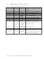
FOR CONTRACTS WITH AN ESTIMATED VALUE OF LESS
THAN OR EQUAL TO $1,000,000, THE FEE WILL BE
$175.
FOR CONTRACTS WITH AN ESTIMATED VALUE OF GREATER
THAN $1,000,000, THE FEE WILL BE $350.
PURSUANT TO RECENT AMENDMENTS TO STATE LAW
EXPECTED TO TAKE EFFECT PRIOR TO THE AWARD OF
THIS CONTRACT, PURCHASE CONTRACTS SUBJECT TO
GML SECTION 103, (INCLUDING CONTRACTS FOR SERVICE
WORK, BUT EXCLUDING ANY PURCHASE CONTRACTS
NECESSARY FOR THE COMPLETION OF A PUBLIC WORKS
CONTRACT PURSUANT TO ARTICLE EIGHT OF THE LABOR
LAW) SHALL BE AWARDED ON THE BASIS OF BEST VALUE
AS DEFINED IN THE STATE FINANCE LAW SECTION 163.
STATE FINANCE LAW SECTION 163(1)(J) DEFINES BEST
VALUE AS THAT BID OR OFFER THAT OPTIMIZES
QUALITY, COST, AND EFFICIENCY.
ACCORDINGLY, THIS CONTRACT WILL BE AWARDED ON THE
BASIS OF BEST VALUE TO THE CITY, WHICH WILL BE
DETERMINED TO BE THE LOWEST RESPONSIVE AND
RESPONSIBLE BIDDER, PROVIDED HOWEVER THAT THE
MAYOR MAY, PURSUANT TO CHARTER SECTION 313(B)(2),
DIRECT THE AGENCY TO AWARD THIS CONTRACT TO OTHER
THAN THE LOW BIDDER IN THE BEST INTERESTS OF THE
CITY BY DETERMINING, IN WRITING, THAT ANOTHER BID
OPTIMIZES QUALITY, COST AND EFFICIENCY AND IS
THUS THE BEST VALUE TO THE CITY. AN AWARD TO
OTHER THAN THE LOW BIDDER MAY ONLY BE MADE TO A
BIDDER WHOSE BID IS WITHIN 10% OF THE LOWEST
RESPONSIVE AND RESPONSIBLE BID.
*************************************************
THIS BIDBOOK MUST BE RETURNED INTACT WITH THE
PAGES IN SEQUENCE AS ORIGINALLY RECEIVED. REMOVAL
OF ANY PAGE(S) MAY BE CAUSE FOR BID
DISQUALIFICATION.
*************************************************
THIS BID IS FOR THE PROCUREMENT OF AMBULANCES
FOR THE FIRE DEPARTMENT OF THE CITY OF NEW YORK.
B 003
PERIOD OF CONTRACT:
DECEMBER 1, 2013 THRU NOVEMBER 30, 2016
THE CITY RESERVES THE RIGHT, PRIOR TO CONTRACT
REGISTRATION, TO CHANGE (ADJUST) THE START AND
END DATES AS NOTED ABOVE. THE CITY FURTHER
RESERVES THE RIGHT TO CHANGE (ADJUST) THESE
DATES AFTER CONTRACT REGISTRATION TO REFLECT
THE ACTUAL COMPTROLLER'S REGISTRATION DATE.
CONTRACT QUANTITIES: QUANTITIES SPECIFIED HEREIN
ARE ESTIMATES BASED ON EXPERIENCE. THE
QUANTITIES TO BE ORDERED ARE ONLY THOSE NEEDED BY
THE AGENCY. THE CITY WILL NOT BE COMPELLED TO
ORDER ANY SPECIFIC QUANTITY OF ANY ITEM, NOR WILL
THE CITY BE LIMITED TO THE QUANTITY SPECIFIED.
QUALIFICATIONS OF BIDDERS: BIDS WILL BE ACCEPTED
ONLY FROM MANUFACTURERS OR THEIR AUTHORIZED
DISTRIBUTORS WHO HAVE BEEN ACTIVELY ENGAGED IN
THE SALE OR MANUFACTURE OF AMBULANCES AND OR
EQUIPMENT OR OTHER VEHICLES FOR A PERIOD OF NOT
LESS THAN FIVE YEARS.
************* BIDDER CERTIFICATE ****************
EACH BIDDER MUST INDICATE THE MANNER IN WHICH HE
INTENDS TO MEET THE BID SPECIFICATION(S) BY
COMPLETELY AND COMPETENTLY FILLING OUT THE
"BIDDERS CERTIFICATE" ATTACHED TO THE BID
SPECIFICATIONS, AND SUBMITTING IT WITH HIS BID
PROPOSAL.
THE BIDDERS CERTIFICATE SHALL BECOME AN INTEGRAL
PART OF THIS CONTRACT AND SCHEDULE. THERE SHALL
BE "NO" SUBSTITUTION, NOR MODIFICATION OF BID
SPECIFICATIONS WITHOUT THE WRITTEN CONSENT OF
THE DIVISION OF MUNICIPAL SUPPLY SERVICES ONCE
THE PURCHASE ORDER IS GENERATED.
PRE-CONSTRUCTION MEETING: A PRE-CONSTRUCTION
CONFERENCE SHALL BE HELD IN THE CITY OF NEW YORK
FOLLOWING AWARD OF CONTRACT. THE CHASSIS AND BODY
MANUFACTURER SHALL PROVIDE QUALIFIED ENGINEERING
PERSONNEL TO ATTEND THIS MEETING. EACH AND EVERY
PORTION OF THE VEHICLE SHALL BE REVIEWED AT THIS
MEETING. APPROVAL DRAWINGS FOR CONSTRUCTION SHALL
BE COMPLETED FOR THIS PRE-CONSTRUCTION MEETING.
ALL COST OF SUCH A MEETING SHALL BE AT
MANUFACTURER'S EXPENSE.
B 004
ALL VEHICLES ARE TO BE DELIVERED WITHIN THE
SPECIFICATIONS GUIDELINES. ALL VEHICLES
DELIVERED UNDER THIS CONTRACT MUST BE DELIVERED
CLEAN AND HAVE FULL TANKS OF FUEL.
DELIVERY POINT:
FIRE DEPARTMENT; CITY OF NEW YORK
48-58 35TH STREET
LONG ISLAND CITY, NEW YORK
ATTN: DIRECTOR OF FLEET SERVICES
718 784-6500
VEHICLES OFFERED MUST COMPLY WITH ALL APPLICABLE
NEW YORK STATE AND FEDERAL REGULATIONS FOR
MOTORIZED VEHICLES.
VEHICLES WITH HANDICAP ACCESS MUST COMPLY WITH
THE AMERICANS WITH DISABILITIES ACT (ADA).
ALL VEHICLES THAT REQUIRE STATE INSPECTION SHALL
BE DELIVERED WITH A VALID NYS INSPECTION STICKER.
INVOICE IS TO BE SENT TO THE ADDRESS INDICATED ON
THE PURCHASE ORDER.
DELIVERY SCHEDULE: PER SPECIFICATION.
ALL PRICES ARE TO BE ON THE BASIS OF F.O.B.
DELIVERY POINT, UNLOADED, AND INSIDE. ALL
DELIVERY CHARGES ARE TO BE INCLUDED IN PRICES
BID.
NOTWITHSTANDING ANY PROVISIONS CONTAINED IN THIS
CONTRACT, THE USING AGENCY, IN CONJUNCTION WITH
AND WITH THE APPROVAL OF THE CITY OF NEW YORK'S
DEPARTMENT OF CITYWIDE ADMINISTRATIVE SERVICES,
DIVISION OF MUNICIPAL SUPPLY SERVICES, MAY
ADJUST THE DELIVERY SCHEDULE BASED ON PILOT
INSPECTIONS, CHANGES, OR AMPLIFICATIONS IN
SPECIFICATIONS. THIS PROVISION SHALL ALSO APPLY
TO ENGINEERING CHANGES THAT REQUIRE COMPLIANCE
WITH FEDERAL, STATE OR LOCAL MOTOR VEHICLE SAFETY
STANDARDS.
ANY FRAME MODIFICATIONS TO THE VEHICLE SHALL BE
PERFORMED IN ACCORDANCE WITH OEM RECOMMENDED
PROCEDURES SUCH AS THE PROCEDURES FOLLOWED BY THE
FORD QVM QUALIFIED VEHICLE MODIFIERS AND
GM SVM SPECIAL VEHICLE MANUFACTURER PROGRAMS.
A CERTIFICATION THAT THESE PROCEDURES WERE
FOLLOWED MAY BE REQUIRED.
GUARANTEE/WARRANTY: WARRANTY OFFERED SHALL MEET
OR EXCEED THAT STATED IN THE ATTACHED
SPECIFICATION(S).
B 005
RESEARCH AND DEVELOPMENT (R&D) CLAUSE: THIS
DEPARTMENT RESERVES THE OPTION, FOR THE PURPOSE
OF RESEARCH AND DEVELOPMENT, TO MODIFY OR
RECONFIGURE VEHICLES PURCHASED UNDER THIS
CONTRACT. THESE CHANGES MAY INVOLVE THE
MODIFICATION OR THE SUBSTITUTION OF ANY
COMPONENT, AS WELL AS CONTINGENT EQUIPMENT
INCLUDING, BUT NOT LIMITED TO, THE DRIVE TRAIN,
BODY, SUB ASSEMBLIES AND SUPPORTING COMPONENT
HARDWARE. THESE MODIFICATIONS AND/OR
SUBSTITUTIONS MAY ALSO INCLUDE CHANGES TO
INTRODUCE NEW PRIMARY PROPULSION SYSTEMS (I.E.
DIESEL, C.N.G., ELECTRIC-HYDRAULIC, HYBRID
POWER, ETC.) TO VEHICLES AND EQUIPMENT COVERED
WITHIN THE CONTRACT PARAMETERS.
THOSE VEHICLES THAT MAY BE SELECTED FOR RESEARCH
AND DEVELOPMENT MODIFICATIONS AS DESCRIBED ABOVE,
WILL BE DICTATED BY TECHNOLOGICAL ADVANCES AND
INNOVATIONS WITHIN THE INDUSTRY AS THEY BECOME
AVAILABLE, AND WILL BE QUANTIFIED ON EACH
PURCHASE ORDER.
IN THE EVENT THAT THE CITY ELECTS TO INVOKE
THIS CLAUSE, THE CITY SHALL NOTIFY THE VENDOR
IN WRITING OF SUCH DECISION.
INSPECTION:
THE INSPECTON OF THE ITEMS CONTAINED HEREIN SHALL
BE MADE BY
NYC DEPT. OF CITYWIDE ADMINISTRATIVE SERVICES
DIVISION OF MUNICIPAL SUPPLY SERVICES
BUREAU OF QUALITY ASSURANCE
1 CENTRE STREET, 18TH FLOOR
NEW YORK, N.Y. 10007
IT SHALL BE THE RESPONSIBILITY OF THE CONTRACTOR
TO KEEP THE CITY APPRISED AS TO WHEN ANY ITEMS
WILL BE READY FOR INSPECTION. CONTRACTORS ARE
INSTRUCTED TO CONTACT, BUREAU OF QUALITY
ASSURANCE (BQA) AT 212 669-7518/7519 AT LEAST
FOURTEEN DAYS PRIOR TO THE INSPECTION DATE.
THE INSPECTION OF THESE ITEMS SHALL BE MADE AT
ANY OR ALL OF THE FOLLOWING LOCATIONS:
CONTRACTOR'S FACTORY OR SERVICE STATION,
SUB-CONTRACTOR'S FACTORY OR SERVICE STATION OR
DELIVERY LOCATION.
B 006
THE CITY REPRESENTATIVE FOR BQA SHALL BE
PERMITTED FULL ACCESS TO ALL PARTS OF THE PLANT
WHEN AND WHERE WORK ON THIS CONTRACT IS BEING
PERFORMED. REPRESENTATIVES FOR BQA SHALL BE
NOTIFIED OF AND GIVEN AN OPPORTUNITY TO BE
PRESENT AT ALL TESTS OF MATERIAL OR WORKMANSHIP
AND SHALL BE PROVIDED WITH ALL NECESSARY
FACILITIES IN EXAMINING AND MEASURING ALL PARTS
AND EQUIPMENT TESTS. THE EXPENSE OF ALL TESTS
(LABORATORY, SHOP AND FIELD) SHALL BE BORNE BY
THE CONTRACTOR AND BE INCLUDED IN UNIT PRICE.
ANY RECEIPT GIVEN TO THE CONTRACTOR BY A
REPRESENTATIVE OF THE DEPARTMENT RECEIVING THE
ITEM(S) SHALL NOT CONSTITUTE FINAL OR OFFICIAL
CITY ACCEPTANCE. UPON COMPLETION OF TESTS AND
EVALUATION, FINAL ACCEPTANCE SHALL ONLY BE
GRANTED BY THE BUREAU OF QUALITY ASSURANCE AT A
LOCATION TO BE DETERMINED BY THE CITY OF NEW
YORK.
GOVERNMENT MANDATED PROGRAM PRICE ADJUSTMENT:
AN ADJUSTMENT IN PRICE MAY BE PERMITTED IF A
GOVERNMENT MANDATED PROGRAM (E.G., NEW STANDARD
FOR EMISSIONS) TAKES EFFECT, SUITABLE
DOCUMENTATION IS FURNISHED TO THE NYC DEPARTMENT
OF CITYWIDE ADMINISTRATIVE SERVICES (DCAS) AND
DCAS DETERMINES THE REQUESTED PRICE CHANGE IS
VERIFIABLE AND IS REASONABLE. THE EFFECTIVE DATE
FOR THE PRICE INCREASE WILL BE AS STATED IN THE
CONTRACT MODIFICATION.
PRICE ESCALATION
A PRICE INCREASE WILL BE ALLOWED ON THIS CONTRACT
AFTER IT HAS BEEN IN EFFECT FOR ONE YEAR.
PRICES OF AMBULANCES SHALL BE ADJUSTED ACCORDING
TO A FORMULA TAKING INTO ACCOUNT CHANGES IN THE
PRODUCER PRICE INDEX (PPI) AND CHANGES IN THE
MANUFACTURERS' PRICES FOR THE CHASSIS AND RADIO
EQUIPMENT. THE PRICE OF THE COMPLETE AMBULANCE
SHALL BE DIVIDED INTO THREE COMPONENTS: CHASSIS,
RADIO EQUIPMENT, AND ALL OTHER PARTS, PROFIT,
OVERHEAD AND MANUFACTURING COSTS (MANUFACTURING
COSTS). THE CHASSIS AND RADIO EQUIPMENT SHALL BE
AT OEM COST AND SHALL NOT INCLUDE ANY MARKUPS OR
ADDITIONS.
THEREAFTER, ONE PRICE INCREASE REQUEST
WILL BE CONSIDERED PER YEAR. PRICE DECREASES
MUST BE OFFERED AS SOON AS THEY BECOME AVAILABLE
OR IMMEDIATELY UPON NOTIFICATION BY THE DIVISION
OF MUNICIPAL SUPPLY SERVICES (DMSS).
B 007
NOTIFICATION OF PRICE CHANGES MUST BE ADDRESSED
IN WRITING TO THE:
ASSISTANT COMMISSIONER, PROCUREMENT
DEPARTMENT OF CITYWIDE ADMINISTRATIVE SERVICES,
DIVISION OF MUNICIPAL SUPPLY SERVICES (DMSS),
1 CENTRE STREET, 18TH FLOOR,
NEW YORK, NEW YORK 10007
THIS CONTRACT MAY BE TERMINATED BY THE CITY OF
NEW YORK IN THE EVENT THAT PRICE INCREASES OR
DECREASES DO NOT REFLECT INDUSTRY DOCUMENTATION.
NO PRICE CHANGE WILL BECOME EFFECTIVE UNLESS
APPROVED BY THE ASSISTANT COMMISSIONER PROCUREMENT OR HIS/HER DESIGNEE.
30 DAYS NOTICE MUST BE GIVEN ON ALL PRICE CHANGE
REQUESTS. PRICE CHANGE REQUESTS, IF APPROVED,
WILL EFFECT FUTURE ORDERS ONLY. ANY PURCHASE
ORDER THAT HAS ALREADY BEEN GENERATED WILL
REFLECT THE THEN CURRENT PRICE.
THE DOCUMENTATION ON PRICE INCREASES MUST
SUBSTANTIATE THE CHANGE IN PRICE. ACCEPTABLE
DOCUMENTATION INCLUDES, BUT IS NOT LIMITED TO:
1. MANUFACTURER NOTICE OF PRICE INCREASE
2. CHANGES IN THE PRODUCER PRICE INDEX, AS
DESCRIBED BELOW.
(VENDOR MUST HAVE AND SUPPLY BOTH.)
FOR SUBSEQUENT CONTRACT YEARS, THE PRICE OF THE
COMPLETE AMBULANCE SHALL BE ARRIVED AT BY ADDING
THE ADJUSTED CHASSIS COST, THE ADJUSTED RADIO
EQUIPMENT COST, AND THE ADJUSTED MANUFACTURING
COST. THE CHASSIS AND RADIO EQUIPMENT COSTS SHALL
BE ADJUSTED TO THE SAME EXTENT AS THE OEM COST TO
THE PRIME VENDOR FOR THESE ITEMS, I.E. ANY
CHANGES WILL BE DIRECTLY PASSED ALONG. THE
MANUFACTURING COST SHALL BE ADJUSTED BASED ON THE
THE PPI INDEX SERIES ID WPU141302, TRANSPORTATION
EQUIPMENT, COMPLETED VEHICLES ON PURCHASED
CHASSIS.
THE MANUFACTURING COST IS DEFINED AS THE MATERIAL
COST OF THE VEHICLE. THIS AMOUNT IS ARRIVED AT BY
TAKING BID PRICE MINUS CHASSIS COST MINUS RADIO
EQUIPMENT COST MINUS PROFIT, OVERHEAD, AND
ADMINISTRATIVE COSTS. INSERT THIS PRICE IN THE
BOX ON PAGE C001.
B 008
PRICE CHANGE CALCULATIONS WILL BE MADE UTILIZING
THE PRODUCER PRICE INDEX(ES) STATED BELOW, AS
COMPILED BY THE U.S. DEPARTMENT OF LABOR/BUREAU
OF LABOR STATISTICS. THE PRICE CHANGE CALCULATION
WILL BE BASED ON THE PERCENT CHANGE FROM THE
BASE DATE TO THE MOST RECENT ACTUAL DATE.
ONLY THE MOST RECENT ACTUAL DATA WILL BE USED,
NOT PRELIMINARY. ALL INDEXES ARE SUBJECT TO
REVISION FOUR (4) MONTHS AFTER ORIGINAL
PUBLICATION.
THE BASE DATE FOR THE PURPOSES OF THIS CONTRACT
IS: DECEMBER 2013.
ONCE A PRICE INCREASE HAS BEEN GRANTED, IF A
SECOND PRICE INCREASE IS REQUESTED, THE BASIS FOR
THAT INCREASE WILL BE THE ACTUAL UTILIZED FOR THE
FIRST INCREASE.
PRICE CHANGE CALCULATIONS FOR THE MANUFACTURING
COST WILL BE BASED ON THE PERCENT CHANGE FOR
TRANSPORTATION EQUIPMENT, COMPLETED VEHICLES ON
PURCHASED CHASSIS.
SERIES ID: WPU141302
ADJUSTED PRICE = MFCG COST X {1 + (B - A)/A}
WHERE: MFCG COST = MANUFACTURING COST
A = PPI FOR THE BASE MONTH
B = MOST RECENT ACTUAL PPI
EXAMPLE CALCULATION OF PRICE ADJUSTMENT:
MANUFACTURING PRICE: $20,000
BASE PPI:
134.3
CURRENT PPI:
137.1
ADJ PRICE =
=
=
=
=
$20000 X {1 + (137.1-134.3)/134.3}
$20000 X {1 + (2.8)/134.3}
$20000 X {1 + .0208}
$20000 X 1.0208
$20416.98
THE ADJUSTED CONTRACT PRICE OF THE COMPLETE
AMBULANCE IS THAN CALCULATED AS THE SUM OF THE
BASELINE (PROFIT, OVERHEAD, AND ADMINISTRATIVE
COSTS) PLUS THE ADJUSTED MANUFACTURING COST
PLUS THE ADJUSTED PRIME VENDOR COSTS FOR THE
CHASSIS AND RADIO EQUIPMENT.
B 009
INSPECTION EXPENSE:
WITHIN 30 DAYS OF RECEIPT OF THE PURCHASE ORDER,
THE SUCCESSFUL VENDOR MUST ISSUE A CHECK IN THE
AMOUNT OF $25,000.00 TO THE DEPARTMENT OF CITYWIDE
ADMINISTRATIVE SERVICES FOR INSPECTION EXPENSES.
THIS IS TO COVER TRAVELING EXPENSES OF THE
CITY'S REPRESENTATIVES. THE VENDOR MUST INCLUDE
THIS AMOUNT ON THEIR FIRST INVOICE FOR
REIMBURSEMENT. MAIL CHECK TO:
DEPARTMENT OF CITYWIDE ADMINISTRATIVE SERVICES
DIVISION OF MUNICIPAL SUPPLY SERVICES
BUREAU OF QUALITY ASSURANCE, 18TH FLOOR
1 CENTRE STREET
NEW YORK, N.Y. 10007
WHEN DELIVERED,EACH VEHICLE/APPARATUS MUST BE
COMPLETELY ASSEMBLED, SERVICED AND READY FOR
OPERATION. THIS INCLUDES ANY AUXILIARY UNITS
ATTACHED OR MOUNTED TO BASIC UNIT. ANY EXPOSED
CHAIN OR GEAR SHALL BE PROVIDED WITH A SUITABLE
GUARD.
TITLE AND RISK OF LOSS: WILL REMAIN THE
CONTRACTOR'S UNTIL THE COMPLETE UNIT IS FINALLY
DELIVERED AND ACCEPTED BY THE CITY.
VENDOR WILL DELIVER WITH THE VEHICLE ALL FORMS
REQUIRED BY THE NEW YORK STATE DEPARTMENT OF
MOTOR VEHICLES TO REGISTER AND OBTAIN TITLE OF
THE VEHICLE. THESE FORMS INCLUDE MV-82
(REGISTRATION/TITLE APPLICATION), BILL OF SALE,
AND THE MANUFACTURERS CERTIFICATE OF ORIGIN
(PROOF OF OWNERSHIP).
UNLESS OTHERWISE INSTRUCTED, THE AGENCY NAMED
ON THE TITLE AND REGISTRATION FORMS WILL BE THE
SAME AS THE AGENCY NAMED ON THE PURCHASE ORDER.
VEHICLES MAY BE ORDERED WITH OPTIONAL EQUIPMENT.
ALL OEM OPTIONS ORDERED WITH THE VEHICLE SHALL
BE AT DEALER COST. NON-OEM DEALER INSTALLED
OPTIONS SHALL BE AT DEALER COST +10%. PRICE
QUOTATIONS FOR DEALER INSTALLED OPTIONS MUST BE
PROVIDED PRIOR TO ISSUANCE OF A PURCHASE ORDER.
THE VEHICLE, WHEN DELIVERED, MUST MEET ALL
APPLICABLE FEDERAL, NEW YORK STATE AND NEW YORK
CITY LAWS (INCLUDING, FOR EXAMPLE, BUT NOT
LIMITED TO, SECTION 86.004-11 OF THE CODE OF
FEDERAL REGULATIONS).
AT THE TIME OF BID SUBMISSION, VENDOR MUST
INCLUDE IN BID THE PRICING FOR ALL KNOWN
TECHNOLOGIES REQUIRED TO MEET THE CURRENT
REGULATIONS AND THE PRICING FOR ANY TECHNOLOGY
ALREADY DEVELOPED TO MEET FUTURE REQUIREMENTS.
B 010
IF, AFTER ISSUANCE OF A PURCHASE ORDER UNDER
THIS CONTRACT, NEW GOVERNMENTAL REGULATIONS ARE
PROMULGATED AND NEW EQUIPMENT IS REQUIRED TO
MEET THESE REGULATIONS AND THE EXTRA COST FOR
THIS EQUIPMENT WAS NOT ANTICIPATED, AND COULD NOT
HAVE BEEN ANTICIPATED, WHEN THE BID WAS SUBMITTED
AND THE PURCHASE ORDER WAS ISSUED, AWARDED VENDOR
MAY BE ELIGIBLE FOR A PRICE INCREASE ON THE
PURCHASE ORDER. PLEASE BE ADVISED THAT IF NO NEW
TECHNOLOGY IS REQUIRED, VENDOR WILL NOT BE
ELIGIBLE FOR A PRICE INCREASE.
THE FOLLOWING MINIMAL REQUIREMENTS MUST BE
MET FOR DCAS TO CONSIDER A PRICE INCREASE:
1.
VENDOR MUST SUBMIT A LETTER REQUESTING THE
INCREASE, STATING THE DOLLAR AMOUNT OF THE
INCREASE AND SPECIFICALLY STATING WHAT THE
INCREASE WILL COVER;
2.
VENDOR MUST INCLUDE A CERTIFICATION FROM THE
REGULATORY AUTHORITY (THE NYC DEPARTMENT OF
ENVIRONMENTAL PROTECTION) THAT THE PROPOSED
SOLUTION BRINGS THE VEHICLE IN COMPLIANCE
WITH THE CURRENT EMISSION LAWS; AND
3.
A MANUFACTURER'S INVOICE SHOWING THE
VENDOR'S TOTAL COST FOR THE EQUIPMENT,
INCLUDING INSTALLATION. VENDOR CANNOT CHARGE
THE CITY MORE THAN 10 % ABOVE THE VENDOR'S
COST FOR THE EQUIPMENT, INCLUDING
INSTALLATION.
THE REQUEST FOR THE PRICE INCREASE AND ALL
SUPPORTING DOCUMENTATION IS TO BE SENT IN WRITING
TO:
ASSISTANT COMMISSIONER - PROCUREMENT
DEPT OF CITYWIDE ADMINISTRATIVE SERVICES
DIVISION OF MUNICIPAL SUPPLY SERVICES (DMSS)
1 CENTRE STREET, 18TH FLOOR
NEW YORK, NY 10007
A MINIMUM OF 30 DAYS ADVANCE NOTICE IS
REQUIRED FOR ALL SUCH REQUESTS.
THE DETERMINATION TO APPROVE A PRICE INCREASE
REQUEST WILL BE AT THE SOLE DISCRETION OF THE
ASSISTANT COMMISSIONER - PROCUREMENT.
THE PRICE INCREASE, IF APPROVED, WILL BE
REFLECTED IN A WRITTEN MODIFICATION TO THE
CONTRACT. THE EFFECTIVE DATE OF THE PRICE
INCREASE WILL BE AS STATED IN THE MODIFICATION.
B 011
BASIS FOR AWARD: THE AWARD, FOR ITEMS, CLASSES/
ZONES IN THIS SCHEDULE, SHALL BE BASED ON THE
LOWEST RESPONSIVE AND RESPONSIBLE BIDDER, MEETING
OR EXCEEDING SPECIFICATIONS FOR OVERALL
PERFORMANCE.
USAGE REPORT
A USAGE REPORT SHOWING AGENCY, ITEM DESCRIPTION,
UNIT OF ISSUE, QUANTITY ORDERED AND DOLLAR VALUE
OF ALL ITEMS ORDERED IS REQUIRED ON A QUARTERLY
BASIS.
THE FIRST REPORT WILL BE REQUIRED THREE (3)
MONTHS AFTER CONTRACT START DATE,
SUBSEQUENT REPORTS ARE REQUIRED EVERY THREE (3)
MONTHS THEREAFTER.
REPORTS SHOULD COVER THE CURRENT PERIOD AS WELL
AS TOTAL CONTRACT PERIOD TO DATE. THE REPORT MAY
BE SUBMITTED IN HARD COPY, ON CD ROM, OR VIA
E-MAIL.
THE REPORT SHALL BE FORMATTED TO INCLUDE: THE
CONTRACT NAME, RC NUMBER AND TERM OF THE CONTRACT
AT THE TOP. THE REPORT SHALL INDICATE THE PERIOD
OF TIME COVERED BY THE REPORT. THE REPORT IS TO
BE ORGANIZED TO SHOW AGENCY, ITEM ORDERED, UNIT
OF ISSUE, QUANTITY ORDERED AND DOLLAR VALUE.
THE USAGE REPORT SHALL BE SENT TO THE
ATTENTION OF THE PROCUREMENT ANALYST WHOSE
NAME IS LISTED ON PAGE B001, AT THE FOLLOWING
ADDRESS:
CITY OF NEW YORK
DEPARTMENT OF CITYWIDE ADMINISTRATIVE SERVICES
DIVISION OF MUNICIPAL SUPPLY SERVICES
1 CENTRE STREET, 18TH FLOOR
NEW YORK, NY 10007
NOTE:
THIS CONTRACT MAY BE SUBJECT TO VENDEX PRIOR TO
AWARD. SHOULD VENDEX BE REQUESTED, VENDOR IS
ADVISED THAT THE REQUESTED INFORMATION WILL BE
REQUIRED WITHIN 30 (THIRTY) DAYS.
FAILURE TO RESPOND IN THE THIRTY DAY TIME FRAME
MAY BE CAUSE FOR BID DISQUALIFICATION.
VENDEX FORMS ARE AVAILABLE FOR DOWNLOAD FROM:
WWW.NYC.GOV/VENDEX
PLEASE SEE PAGE BOO3 FOR ADDITIONAL VENDEX
INFORMATION.
B 012
DESCRIPTION
QUANTITY
UOI
UNIT PRICE
EXTENSION
EACH
COMM. C070 03
$________ $___________
CLASS/ZONE AWARD 01
------------------ITEM NUMBER:
1.
AMBULANCES TYPE I:PER ATTACHED FDNY SPECIFICATION
DATED JANUARY 31, 2013
BIDDERS TAKE NOTE !!
BIDDERS SHOULD LIST THE COST FOR THE
TRUCK CHASSIS AND RADIO EQUIPMENT IN THE
SPACE BELOW.
CHASSIS $..........
RADIO EQUIP $..........
MANUFACTURING COST $............
BIDDER TO INCLUDE MATERIAL COST:
(SEE PRICE ADJUSTMENT CLAUSES)
FAILURE TO INCLUDE MATERIAL COST WILL PRECLUDE
ANY FUTURE PRICE ADJUSTMENT.
THE FDNY RESERVES THE RIGHT TO ORDER DIFFERENTLY
CONFIGURED VEHICLES FOR THE PURPOSE OF TESTING
NEW TECHNOLOGIES AND INNOVATIONS.
PRIOR TO SUBMITTING ANY SUCH ORDER, THE AWARDED
VENDOR WILL BE ADVISED BY LETTER OF THE FDNY
INTENT AND WILL BE ASKED TO PROVIDE THE COST
DIFFERENTIAL, IF ANY, FOR THE DIFFERENTLY
CONFIGURED VEHICLE. NO ORDER FOR SUCH A VEHICLE
WILL BE ISSUED PRIOR TO FDNY APPROVING THE COST
DIFFERENTIAL.
FDNY WILL ONLY PAY THE APPROVED COST
DIFFERENTIAL, IF ANY, AS DESCRIBED ABOVE.
IN ORDER TO REFLECT AND ACCOUNT FOR ANY
ADDITIONAL COSTS FOR THESE RESEARCH AND
DEVELOPMENT VEHICLES, VENDOR IS TO CALCULATE THE
FOLLOWING:
TAKE THE TOTAL EXTENDED DOLLAR VALUE FOR ITEM #1
ABOVE AND MULTIPLY IT BY .05 (5%). THE RESULTING
FIGURE IS TO BE INSERTED UNDER UNIT PRICE AND
EXTENSION FOR ITEM #1.1 BELOW.
C 001
330.
DESCRIPTION
QUANTITY
ITEM NUMBER:
1.10
RESEARCH AND DEVELOPMENT
UOI
UNIT PRICE
EXTENSION
1.
EACH
COMM. C070 53
$________ $___________
50.
EACH
COMM. C070 03
$________ $___________
50.
EACH
COMM. C070 03
$________ $___________
50.
EACH
COMM. C070 03
$________ $___________
RESEARCH & DEVELOPMENT SHALL BE
5% OF THE TOTAL COST OF ITEM # ONE (1)
INSERT THE DOLLAR AMOUNT IN THE UNIT PRICE
AND EXTENSION COLUMNS AT THE RIGHT.
ITEM NUMBER:
2.
FOUR WHEEL DRIVE (4WD) AMBULANCE OPTION.
CHASSIS SHALL BE AN APPROVED AMBULANCE PACKAGE
AND SHALL BE THE SAME MANUFACTURER AND MODEL
SERIES AS DESCRIBED IN THE SPECIFICATION WITH ALL
NECESSARY OPTIONS FOR 4 WHEEL DRIVE, INCLUDING
BUT NOT LIMITED TO A "SHIFT ON THE FLY" TRANSFER
CASE. THE 4WD AMBULANCE SHALL COMPLY WITH ALL
DIMENSIONS AND PARAMETERS OUTLINED IN THE
SPECIFICATION. THE VENDOR SHALL PROVIDE THE
MANUFACTURER?S LITERATURE ON THE PROPOSED 4WD
CHASSIS WITH THEIR BID.
ITEM NUMBER:
3.
MEDIUM DUTY AMBULANCE CHASSIS OPTION. CHASSIS
SHALL BE A CONVENTIONAL STYLE CAB/CHASSIS AND
SHALL BE THE MANUFACTURER'S APPROVED
AMBULANCE PACKAGE. GROSS VEHICLE WEIGHT RATING
SHALL BE 19,500 LBS MINIMUM.
CURB-TO-CURB TURNING RADIUS SHALL NOT EXCEED 30
FEET. THE BUMPER-TO-BUMPER (VEHICLE CLEARANCE)
TURNING RADIUS SHALL NOT EXCEED 31 FEET. ENGINE
SHALL BE DIESEL POWERED, EIGHT (8) CYLINDER,
CERTIFIED FOR USE WITH #1 AND #2 ULTRA LOW SULFUR
DIESEL FUEL AS WELL AS BIODIESEL BLENDS.
THE ENGINE SHALL HAVE A MINIMUM HORSEPOWER RATING
OF 300 HP @ 2600 RPM AND A MINIMUM TORQUE RATING
OF 660 FT-LBS @ 1600 RPM. TRANSMISSION SHALL BE
AN ALLISON 1000EVS SERIES OR EQUAL, AUTOMATIC,
FIVE (5) SPEED MINIMUM WITH OVERDRIVE, FULL
ELECTRONIC CONTROLS AND PARKING PAWL. THE VENDOR
SHALL PROVIDE THE MANUFACTURER'S LITERATURE ON
THE PROPOSED MEDIUM DUTY CHASSIS WITH THEIR BID.
ITEM NUMBER:
4.
COMPLETE BOOK AND MANUAL PACKAGE AS DETAILED
IN SECTION 13 OF THE ATTACHED SPECIFICATION.
C 002
DESCRIPTION
QUANTITY
ITEM NUMBER:
5.
COMPLETE DIAGNOSTIC EQUIPMENT PACKAGE AS
DETAILED IN SECTION 16 OF THE ATTACHED
SPECIFICATIONS.
ITEM NUMBER:
6.
COMPLETE TRAINING PACKAGE AS DETAILED IN SECTION
17 OF THE ATTACHED SPECIFICATIONS.
ITEM NUMBER:
7.
COMPLETE SET OF ALL EXTERIOR MODULE DOORS WITH
HINGES. ALL DOORS SHALL BE PAINTED AND "READY TO
INSTALL".
TOTAL CLASS OR ZONE AWARD (ITEMS
1.00
THRU
OFFERS OF CASH DISCOUNTS WILL NOT BE CONSIDERED
IN MAKING AN AWARD. PLEASE NOTE BELOW IF YOU
OFFER A CASH DISCOUNT AND, IF SO, THE DISCOUNT
TERMS.
DISCOUNT
TERMS ..... %
..... DAYS
TRADE DISCOUNTS
DO YOU OFFER A TRADE DISCOUNT THAT WOULD REDUCE
THE TOTAL AMOUNT OF YOUR BID?
YES (
)
NO (
)
UNIT PRICE
EXTENSION
50.
EACH
COMM. C070 03
$________ $___________
50.
EACH
COMM. C070 03
$________ $___________
50.
EACH
COMM. C070 03
$________ $___________
7.00 ) 01 ...................$__________
CASH DISCOUNTS
YES ..... NO .....
UOI
PERCENT.................
.................................................
C 003
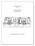
FIRE DEPARTMENT
CITY OF NEW YORK
SPECIFICATION FOR:
TYPE 1
AMBULANCE
DATED: January 31, 2013
SPECIFICATION PREPARED BY FLEET SERVICES DIVISION
SPECIFICATION SUPERSEDES ANY PREVIOUS SPECIFICATION FOR
THIS TYPE VEHICLE
REQ # 201352 1/31/13 TYPE 1 AMBULANCE SPECIFICATION Page 1 of 124
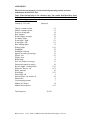
TABLE OF CONTENTS
Section
Page
1.
2.
3.
4.
5.
6.
7.
8.
9.
10.
11.
12.
13.
14.
15.
16.
17.
18.
3-5
6-9
10-14
15-17
18
19
20-47
48-62
63-65
66-82
83
84-86
87-88
89-93
94-97
98-103
104-105
106-112
113
114
115
116-118
119-124
Intent
General Requirements
Chassis and Cab
Engine
Transmission/Driveline/Rear Axle
Tires and Wheels
Body and Special Equipment
Electrical
HVAC System
Two-Way Radio
Paint
Graphics
Books and Manuals
Ambulance Acceptance Testing and Inspection
Delivery Schedule
Warranty
Training
Requirements for Each Ambulance Delivered
Appendix “A”
Appendix “B”
Appendix “C”
Appendix “D”
Bidders Certificate
REQ # 201352 1/31/13 TYPE 1 AMBULANCE SPECIFICATION Page 2 of 124
1.
Intent:
1.1
It is the purpose of this specification to describe a 4 x 2, dual rear wheel,
diesel powered, Type 1 Ambulance. It shall be a conventional truck
cab/chassis with a modular Ambulance body.
1.2
This Ambulance will be used by extensively by the Fire Department City
of New York (FDNY) at various locations throughout the City of New
York. It will be a front line vehicle and subjected to extensive daily use.
It shall have the capability and capacity to carry a full equipment and
personnel load in a safe and secure manner. The Ambulance shall be
engineered and constructed to operate under all conditions with a
minimum amount of downtime.
1.3
The Ambulance shall be manufactured in compliance with the following:
● The specific requirements of this Specification.
● The “Federal Specification for the Star-of-Life Ambulance KKK-A1822F” (dated August 1, 2007) and applicable amendments/revisions in
effect at time of manufacture. This FDNY specification, where
applicable, refers to the relevant sections of KKK-A-1822F.
● The most current edition of part 800 of the New York State Emergency
Medical Service code and applicable amendments in effect at time of
manufacture.
● All State, Federal, and local laws, including but not limited to: Federal
Motor Vehicle Safety Standards (FMVSS); New York State Department of
Health Regulations (10 NYCRR Part 800), and New York State Motor
Vehicle Laws. The Ambulance vendor shall guarantee all Ambulance
chassis provided under the specification are the Original Equipment
Manufacturers (OEM) most current (newest) model year chassis.
● All Ambulances shall be certified by the final stage manufacturer as being
compliant as a "Star-of Life" Ambulance in the year the Ambulance is built.
The final stage manufacturer shall certify in writing, each vehicle's
compliance with all applicable standards during each production cycle.
Note: In the event of a conflict between the text of this specification and the
references cited herein, the text of this specification shall take precedence.
REQ # 201352 1/31/13 TYPE 1 AMBULANCE SPECIFICATION Page 3 of 124
1.
Intent (Continued):
1.4
Consistency is a major concern to FDNY. All Ambulances purchased under
this contract (including any add-on orders) shall be assembled and mounted
to the chassis in a consistent manner. In addition, bolt-on parts used in
module construction shall be interchangeable.
1.5
Workmanship shall be in accordance with the highest standards of the
Ambulance industry and meet or exceed all applicable standards and regulations
that may apply.
1.6
It is not the intent of this specification to cover all details of design and
construction. Nothing stated, implied or omitted from this specification shall
relieve the prime vendor from providing a finished product of high engineering
design and workmanship, fully equipped and capable of performing its intended
function.
1.7
It shall be the responsibility of the vendor to mount the module, wire and install
all accessories, paint, finish and test the completed Ambulance in accordance
with the requirements of this specification.
1.8
The vendor shall be held fully responsible for the design, performance,
reliability and satisfactory operational function of the apparatus / vehicle /
equipment.
1.9
Vehicles shall be delivered “ready for service”. Each vehicle shall have a signed
inspection/check off sheet provided with it at the time of delivery. Any
deficiencies found during this inspection shall be noted on this sheet and
corrected before delivery.
1.10 Upon delivery, the vehicle shall have a valid New York State Department of
Motor Vehicles inspection certificate affixed to it.
1.11 “Heavy duty” is defined as the heaviest duty/highest capacity/longest life
component made for the vehicle by the manufacturer (OEM).
1.12 Tolerances: Where dimensions and tolerances are stated in this specification, the
stated tolerance shall apply. Approximate, or “approx”, where it is mentioned in
this specification, shall be defined as + / - 5%, and shall be at the discretion and
approval of FDNY.
1.13 Where a reference is made such as “As per KKK 1.1.1 +”, the plus sign (+)
shall indicate that the vendor is required to meet the requirements of the relevant
section of KKK-A-1822F plus the text stated under that particular FDNY line
item number in this specification.
REQ # 201352 1/31/13 TYPE 1 AMBULANCE SPECIFICATION Page 4 of 124
1.
Intent (Continued):
1.14 Sheet metal, self-tapping wood or metal screws, nails, rivets, and staples are not
acceptable in/on the Ambulance assembly, without prior written approval by
FDNY. Nutserts™ or nylon threading inserts shall be used wherever possible.
Tapping plates shall be used where specified. Attaching hardware shall be
approved by FDNY.
1.15 All vendor installed wiring, accessories, equipment and options subject to
FDNY approval with regard to equipment selection, layout, placement / location
and final installation. FDNY shall reserve the right to determine any
electrical installations which require constant duty relays.
1.16 “Street side”, as mentioned in this specification shall be denoted as the left side
of the vehicle, and “curb side” shall be denoted as the right side of the vehicle.
1.17 The terms “contractor”, “successful bidder”, “prime vendor”, and “vendor” as
stated in this specification shall be deemed as interchangeable terms which refer
to the same business or entity.
1.18 If a component or option, required by the specification or original equipment
manufacturer, is only available as part of an “option package” it must still be
supplied.
1.19 If a component, option, system or feature is stated in this specification and is not
available from the manufacturer, appropriate written documentation shall be
provided by the vendor to FDNY stating that the specified component, option or
system is not available through that manufacturer. FDNY shall approve any
proposed substitutes to these components or systems.
1.20 FDNY shall determine which areas on the apparatus require padding to prevent
possible injury to personnel.
1.21 FDNY shall reserve the right to adopt federal OSHA requirements for the
vehicle, or at least those relevant sections of these regulations that may protect
the interests of the Department.
1.22 All efforts shall be made to save vehicle weight. Further details shall be
discussed at the preconstruction conference. FDNY shall direct and approve the
material type used in a given area.
REQ # 201352 1/31/13 TYPE 1 AMBULANCE SPECIFICATION Page 5 of 124
2.
General Requirements:
2.1
New Technology Qualification: A "New Technology" is defined as an item or
method of manufacture that has come into the industry within the last three
calendar years. While the main intention of FDNY is to purchase reliable, field
proven products rather than experimental or prototype items, every
consideration shall be given to the evaluation of new technologies. To be
considered “proven technology”, FDNY requires that the item/system proposed
have been utilized on the vendor’s product line and that the vendor submit with
their bid, details of the length of time that the item/system has been in use, the
number of vehicles that the item/system has been installed on and a reference list
of customers.
Note: If a vendor submits a New Technology that fails to meet the “time in
use" requirements, three (3) years minimum, detailed in this specification, then
the vendor shall supply the following information with the bid submission:
1.
A detailed description of the item or method of New Technology, as
well as all engineering data to support the "equal to” requirement.
2.
A list of six (6) large metropolitan fleets that have used the New
Technology on Type 1 Ambulances for a minimum period of one year.
The list shall include the following: a contact person, address, phone
number, Ambulance call volume, and the vehicle “in service” dates.
3.
Sample parts shall be submitted to DCAS/FDNY for evaluation upon
request:
A.
All relevant KKK-A-1822F test data on the New Technology shall
include but not be limited to the following: test dates and results,
photos, and graphs. The vendor shall furnish a contact person at the
test laboratory.
B. Acceptance of any or all New Technologies shall be at the sole
discretion of DCAS/FDNY. Vendors should be aware that all items
and materials that have not been used successfully in the industry for
a three-year period shall be subject to the New Technology
qualification.
2.2 In addition to the above, FDNY reserves the right to invoke the “experimental
technology” clause as defined by DCAS in the bid package accompanying this
specification.
REQ # 201352 1/31/13 TYPE 1 AMBULANCE SPECIFICATION Page 6 of 124
2.
General Requirements (Continued):
2.3 Alternative Construction Methods: The construction methods described in this
specification are based on Ambulance designs that have provided FDNY with
longevity and ease of maintenance/repair. Alternative construction methods may
be acceptable. If the vendor is proposing an alternative construction method that
differs from that described in this specification, then the following procedure shall
be followed:
1) The vendor shall provide a written line-by-line comparison between the
methods described in this specification and what the vendor is proposing. The
comparison shall use the FDNY section number from this specification for easy
cross referencing.
2) The comparison shall clearly demonstrate how the vendor’s alternative design
meets (or exceeds) each section that differs from the specification. All sections
which differ from the specification shall be shown in the comparison. Vendor
construction proposals which are incomplete are unacceptable. The
requirements for the comparison shall include but not be limited to:
engineering drawings and reports, safety and durability testing, material
samples, demonstration/sample vehicles, and anything deemed necessary by
FDNY and/or DCAS to make an effective comparison. A full report depicting
the two methods shall be presented for FDNY and/or DCAS review.
2.4
Thread Sealant: As deemed necessary by FDNY, screws and bolts shall be
pretreated with anaerobic thread sealant and sized according to the calculated
loads and stresses. Vibratite™ coated screws shall also be acceptable with
FDNY approval.
2.5
Electrical Connector Sealer: All vendor installed electrical connections located
under the hood, exposed to the elements or as directed by FDNY shall be
treated with a type of insulating sealer to prevent electrolytic action and
corrosion.
2.6
Welding: All welds shall be in accordance with American Welding Society
Standard D1.1, and done by certified welders. All welding shall be subject to
physical inspection and/or laboratory testing at the discretion of FDNY.
2.7
Access Panels: All service access panels shall be well secured, of maximum
size, and located to facilitate access to electrical / mechanical connections. All
service access panels shall be secured with non-keyed, recessed, security
latches made by Spanner™.
2.8
Access to electrical power distribution panels/terminals, which include the
circuit breaker panels, shall be through an external lockable compartment. This
compartment shall be weather tight and properly vented.
REQ # 201352 1/31/13 TYPE 1 AMBULANCE SPECIFICATION Page 7 of 124
2.
General Requirements (Continued):
2.9
Service Loops: All final stage/vendor installed or modified components
(including, but not limited to, hose, cable, and tube connected devices) shall be
heavy duty and have at least a six inch (6”) service loop of cable, tubing or
hose. Hoses and tubes, beginning and terminating on the same panel, shall be
installed with at least a two-inch (2”) service loop to facilitate repair and
replacement.
2.10
Grommets and Sealing: All hose, wire cable, and tubing passing through
panels or any metal shall have a heavy-duty rubber grommet and/or edge guard
and sealed weather tight. All hose, wire, cables, and tubing passing through the
patient compartment, bulkhead, or the vehicle fire-wall shall be sealed with the
appropriate form of fire resistive sealant that shall prevent dust or moisture
penetration.
2.11
All wiring, hoses and fuel lines passing under the cab shall have a protective
shield. All shield designs shall be approved by FDNY before construction.
2.12
The use of electrical/friction tape on connections/splices or for wrapping wires
is not acceptable. All wire terminals, terminations connectors, butts or splices
shall be weather tight, protected by self sealing heat shrink tubing or “liquid
electrical tape”, where heat shrink is not usable. All wiring shall be enclosed in
protective loom, and this loom shall be protected by chafe guard where
necessary. Wherever possible module electrical connectors shall be “Deutsch,
Gold Terminal, Waterproof Connectors” All terminals and butt connectors ends
shall be double-crimped with the proper double-crimping tool and then
soldered and covered with self sealing heat shrink tubing. Wherever possible
wiring shall be continuous end to end.
2.13
ECK Anti Corrosion Spray™ (available from Van Nay LLC, 847-931-7899)
shall be used on all contact areas of dissimilar metals to prevent oxidation and
corrosion. FDNY reserves the right to direct which areas require this
treatment.
2.14
Operation and Performance: As per KKK 3.4.1+
• The vehicle shall be capable of performing under environmental conditions
and operating conditions common to New York City. FDNY Ambulances
run continuously throughout the shift. Ambulances may patrol at slow
speeds or idle between calls with cab and patient environmental systems
operating at their highest settings.
2.15
Vehicle Lubrication: As per KKK 3.6.2
2.16
Recovered Materials: As per KKK 3.3
2.17
Temperature Conditions: As per KKK 3.4.2
REQ # 201352 1/31/13 TYPE 1 AMBULANCE SPECIFICATION Page 8 of 124
2.
General Requirements (Continued):
2.18
Exterior: As per KKK 3.4.2.1
2.19
Interior: As per KKK 3.4.2.2
2.20
Noise and Sound Level Limits Exterior: As per KKK 3.4.3+
• All applicable City of New York noise regulations.
2.21
Intended Use Of Specification: As per KKK 6.1
2.22
Federal Specification Coverage: As per KKK 6.1.1
2.23
Definition Of Government Purchaser: As per KKK 6.1.3
2.24
Price Changes: Refer to the DCAS bid package accompanying this
specification for detailed information on price changes.
REQ # 201352 1/31/13 TYPE 1 AMBULANCE SPECIFICATION Page 9 of 124
3.
Chassis and Cab:
3.1 Chassis Type: Type 1 Ambulance, as per KKK 3.1.2+
● Chassis shall be OEM Manufacturer’s Certified/Designated Ambulance
Package, “Super-Cab” type, KKK approved Ambulance Chassis:
3.2
Cab-Body Provisions: As per KKK 3.9.2
3.3
Controls And Operating Mechanism: As per KKK 3.9.4
3.4
Driver’s Compartment, Cab-Body Structure: As per KKK 3.9.1
3.5
Vehicle Physical Dimensional Requirements: As per KKK 3.4.10
3.6
Wheel base of chassis: 186” approx.
3.7
Cab to Axle (CA) Type 1: As per KKK 3.5.6+
● 84” approx.
3.8
Overall length of chassis: 272” approx
3.9
Overall Ambulance width: 96.5” maximum. This dimension shall be exclusive
of all external hardware, rub rails and mirrors.
3.10 Overall height of Ambulance (loaded): 110” maximum, excluding 2-way radio
antenna(s)
3.11 Ground clearance: 8” minimum
3.12 Length: 24.25’ maximum. Note: Due to the various chassis and body
combinations available, if an optional chassis is chosen, the overall length of the
vehicle may change. This shall be further discussed at the preconstruction
conference.
3.13 Turning Radius: As per KKK 3.4.10.5
3.14 Curb weight: As per KKK 3.5.1
3.15 Payload Capacities: As per KKK 3.5.2 +
•
Payload: 8,549 lbs, minimum
REQ # 201352 1/31/13 TYPE 1 AMBULANCE SPECIFICATION Page 10 of 124
3.
Chassis and Cab (Continued):
3.16 Gross Vehicle Weight Rating (GVWR): As per KKK 3.5.3 +
•
•
•
GVWR: 16,500 lbs, minimum
Front GAWR: 7,000 lbs, minimum
Rear GAWR: 12,000 lbs, minimum
3.17 Angle of Approach, Ramp Breakover, and Departure: As per KKK 3.4.10.4 +
● Deviation from KKK may be necessary to accommodate FDNY rear step
requirements.
3.18 Weight Distribution: As per KKK 3.5.4
3.19 Ratings: As per KKK 3.5.5
3.20 Chassis Frame: As per KKK 3.6.1
3.21 Front Tow Hooks: As approved by FDNY.
3.22 Suspension: As per KKK 3.6.5.6+
● The rear suspension shall be spring or air suspension. The suspension shall
minimize modifications to the OEM chassis in terms of the frame, the
suspension mounting brackets and the exhaust.
● All conversion components shall bolt to the OEM chassis without welding. If
the proposed system is air suspension it shall connect to the OEM chassis
through the OEM front spring brackets and the lateral axle control shall be of
a design that minimizes point-load stress to the OEM frame members.
● Trailing beams shall be forged spring beams that connect to the OEM spring
bracket at the frame, then connect to the top of the axle on the original spring
seat before dropping behind the axle in a “Z” shape and extending to provide
a mounting bracket for the air spring.
●The connection shall provide optimum drive shaft angles to minimize drive
line vibration. Force sensitive shock absorbers shall be provided and custom
tuned for optimum ride comfort.
● The suspension shall provide a minimum of 3” of jounce travel and 3” of
rebound travel. It shall have dual height leveling valves to maintain correct
body height and side-to-side height.
REQ # 201352 1/31/13 TYPE 1 AMBULANCE SPECIFICATION Page 11 of 124
3.
Chassis and Cab (Continued):
3.22 Suspension: As per KKK 3.6.5.6+ (Continued):
●There shall be a “dump” feature to lower the vehicle height automatically when
the street side rear access door is opened. The load height shall automatically
return to normal ride height when the door is closed.
●The dump feature shall have a high speed control to minimize response time.
There shall be a low pressure warning system with and audible warning
device if the air system pressure falls below minimal operational pressure.
● This system shall have the capability to check the left and right air springs
individually. The vendor shall provide complete shop drawings and
documentation for all suspension designs being proposed. FDNY shall
approve the final suspension design.
3.23 Spring Stops: As per KKK 3.6.5.7
3.24 Shock Absorbers: As per KKK 3.6.5.8
3.25 Steering: As per KKK 3.6.6+
• OEM Tilt Steering Wheel with telescoping feature if available OEM.
3.26 Engine Hood: As per KKK 3.9.8 +
● OEM hood shall be vented to provide proper engine cooling. Further details
shall be discussed at the preconstruction conference.
3.27 Cab Floor: OEM carpet and matting shall be removed and the cab floor shall be
coated with black Linex™, or equal with UV protection. All OEM wiring shall
be run through a channel for protection against damage. Texture and coverage
area shall be approved by FDNY.
3.28 Brake System, Service, and Parking: As per KKK 3.6.5.4 +
● The vehicle shall have a Telma™ brake retarder system and shall be the latest
approved model for Ambulance service. It shall be properly sized for the
proposed chassis. Written certification from the brake retarder manufacturer
shall be provided to FDNY.
3.29 Interior colors:
OEM color charts/samples shall be provided at the
preconstruction conference for FDNY review and approval.
REQ # 201352 1/31/13 TYPE 1 AMBULANCE SPECIFICATION Page 12 of 124
3.
Chassis and Cab (Continued):
3.30 Cab Compartment Driver And Passenger Seat: As per KKK 3.9.3+
The cab shall be furnished with two (2) individual high-back driver and
passenger bucket vinyl seats with lumbar adjustment, if available. (OEM
preferred, if available. If not, FDNY reserves the right to approve proposed
substitutes). There shall be armrests provided at both the driver and assistant’s
seating areas. The seats shall be covered with OEM heavy duty artificial leather
or heavy duty vinyl non-absorbent material and meet FMVSS requirements.
Seats shall be fully adjustable, forward and backward. If OEM seats are not
available in vinyl then the vendor shall replace the OEM material with forty (40)
ounce heavy duty commercial vinyl. The color shall match the interior.
Component selection, location and final installation of all components subject to
FDNY approval.
3.31 Air Bags: Driver and Passenger air bags, and side curtain air bags, if available
OEM
3.32 Windshield Wipers And Washers: As per KKK 3.7.4 +
• With OEM Intermittent Wiper Option.
3.33 Horns: As per KKK 3.7.5
3.34 OEM Radio: AM/FM Stereo/Clock.
3.35 Cup Holders: Two mounted in the center console area, right and left side. Cup
holders shall not interfere with the layout of the console and related equipment.
Location and type shall be approved by FDNY
3.36 Map Pockets: OEM or dealer installed, shall be mounted on each door and shall
accommodate an 8 1/2” X 14” current in use FDNY ACR book, minimum
3.37 Air Conditioning: OEM system shall be provided for the cab.
3.38 Power Windows: OEM equipment.
3.39 Power Door Locks: OEM equipment.
3.40 Rear Cab Window: Sliding type, design approved by FDNY.
3.41 Interior power point outlets: 12V “cigarette lighter” style. Six units shall be
installed as directed by FDNY.
3.42 Daytime Running Lights: OEM equipment.
REQ # 201352 1/31/13 TYPE 1 AMBULANCE SPECIFICATION Page 13 of 124
3.
Chassis and Cab (Continued):
3.43
Running Boards: OEM Running Boards, with non-slip top surface. These shall
be installed and supported as recommended by the OEM. If an OEM running
board is not available, the vendor shall propose an alternate unit, which
shall be subject to FDNY approval. NOTE: Tubular type running boards
shall not be acceptable. Component selection and installation subject to
FDNY approval.
3.44
Outside Rearview Mirrors: As per KKK 3.9.5 +
• OEM mirrors, as approved by FDNY at the preconstruction conference, shall
be provided. The vendor shall provide details on the latest optional OEM
mirrors to FDNY. FDNY shall reserve the right to approve any mirror type
or design proposed by the vendor. Further details shall be discussed at the
preconstruction conference.
3.45
Mudflaps: As per KKK 3.9.7.2 +
● Black mud flaps shall have “FDNY” lettering. Type, location and final
installation shall be directed by FDNY
REQ # 201352 1/31/13 TYPE 1 AMBULANCE SPECIFICATION Page 14 of 124
4.
Engine:
4.1
Power Unit, Engine: As per KKK 3.6.3+
Engine shall be 6.7L, minimum, Direct Injection, turbocharged, diesel powered,
300 HP min @ 2,800 RPM – Torque: 660 ft lbs min @ 1,600 RPM. Engine
shall have the capability of running on the following fuels: #1 ultra low
sulfur diesel fuel, #2 ultra low sulfur diesel fuel, and bio-diesel blends.
Written certification shall be supplied by the OEM for all approved fuels.
4.2
Power Unit: As per KKK 3.6.3.1
4.3
Power Unit Components: As per KKK 3.6.4
4.4
Air Filter: As per KKK 3.6.4.2+
● Dry type air cleaner with restriction indicator.
4.5
Oil Filter: As per KKK 3.6.4.1
4.6
Cooling System: As per KKK 3.6.4.5+
● -40 degree F antifreeze protection.
4.7
Coolant hoses: Shall be Dupont Nomex™ if available. If not, FDNY shall
approve any proposed substitute(s)
4.8
Hose Clamps: Shall be constant tension spring type. FDNY shall direct which
hoses that require this type of clamp.
4.9
Engine block heater: 110V, covered receptacle securely mounted in an easily
accessible and protected location – wiring securely mounted, and protected from
chafing.
4.10 Starter: Heavy duty equipment with OEM starter lock out protection.
4.11 Engine High-Idle Speed Control: As per KKK 3.7.6.1 +
● Vehicle shall be equipped with a ‘secure idle’ system that allows the key to
be removed with the engine running and the transmission in Park. If the
vehicle is placed into gear, the engine shall shut down. This system shall be
designed and integrated into the vehicle’s electronic system by the
Ambulance manufacturer.
● Fast idle system: OEM equipment. Electronic engine speed-up control shall
respond to low voltage readings.
REQ # 201352 1/31/13 TYPE 1 AMBULANCE SPECIFICATION Page 15 of 124
4.
Engine (Continued):
4.12
Engine hour meter: Hobbs™ # 98312, (217-753-7798) mounted on dash beside
the steering column as directed by FDNY. This hour meter shall be in addition
to any OEM hour meter(s) provided.
4.13
Speed: As per KKK 3.4.5
4.14
Acceleration: As per KKK 3.4.6
4.15
Gradeability: As per KKK 3.4.7
4.16
Gradaeability at Speed: As per KKK 3.4.7.1
4.17
Minimum Low Speed Gradeability: As per KKK 3.4.7.2
4.18
Engine Low Temperature Starting: As per KKK 3.6.3.2
4.19
Vehicle Performance: As per KKK 3.4.4+
• Performance shall be evaluated under common New York City area
environmental and road conditions.
4.20
Exhaust System: As per KKK 3.6.4.6
4.21
Air Pollution Control: As per KKK 3.6.4.3 +
● Diesel Exhaust Fluid (DEF) tank location shall not impinge upon
compartment space. DEF fill shall be compatible with magnetic nozzle
systems currently in use by the City of New York. Location shall be
approved by FDNY and further details discussed at the preconstruction
conference. Tank shall be full on final delivery.
• The exhaust pipe(s) shall be modified as/if required by Nederman™ (800575-0609) system installation.
• The tail pipe shall exhaust out the right side of the vehicle in back of the rear
wheels. The Ambulance exhaust system shall accept the Nederman™
Vehicle Exhaust System that FDNY has at its Stations. Nederman™ system
shall be installed on each vehicle purchased under this contract.
REQ # 201352 1/31/13 TYPE 1 AMBULANCE SPECIFICATION Page 16 of 124
4.
Engine (Continued):
4.21
Air Pollution Control: As per KKK 3.6.4.3 +
● The vendor shall install all vehicle components required with the
Nederman™ system. This shall include, but not be limited to a magnet
mounted 22 1/2” from the center of the tail pipe to the center of the magnet.
A Nederman™ transmitter shall be installed in the cab, wired to send
disconnect signal when ignition is turned on.
• Final design and workmanship of the Nederman system shall be approved by
FDNY
4.22
Fuel System: As per KKK 3.6.4.4+
●
40 gallon fuel tank capacity, minimum. Tank shall be full at final delivery.
•
Fuel filler tubes shall be equipped with flap type doors and Medeco™
locks. Fuel caps shall be attached to the vehicle by a lanyard. The vendor
shall design a system to prevent fuel from spilling onto paint during
refueling. Modifications of the diesel tank, gauge sender, or fuel cap will
not be accepted.
•
A Cast Aluminum protective guard shall be installed around the fuel fill
location. The fuel fill shall have a locking door with a fleet mastered key
lock. The fuel cap shall be attached to the vehicle by an OEM lanyard.
•
The fuel filler port shall be properly labeled. A permanently attached fuel
filling instruction sign shall be placed above each fuel filler inlet. Signs
shall be engraved plastic or metal with one inch (1”) high white letters on
a green background and state, ”DIESEL FUEL ONLY,” and the wording
“STOP ENGINE: NO SMOKING DURING REFUELING.”
●
Fuel Fill Splash Plates: As per KKK 3.9.7.3
●
Fuel Range: As per KKK 3.4.8
REQ # 201352 1/31/13 TYPE 1 AMBULANCE SPECIFICATION Page 17 of 124
5.
Transmission/Driveline/Rear Axle:
5.1
Automatic Transmission: As per KKK 3.6.5.2 +
● Transmission shall be a six (6) speed with electronic controls.
● Auxiliary External Transmission Oil Cooler: OEM if available, if not:
auxiliary cooler rated capacity for extreme heavy duty service as
recommended by transmission manufacturer – Installed as per manufacturers
instructions – Use of hose shall be directed and approved by FDNY – Hose
used shall be oil rated and securely mounted with rubber covered clamps and
protected by an anti spray/chafe covering entire length (no split plastic ) –
Edge guard/grommets shall be used where passing through or over metal –
Hose fittings shall be SAE flare type, securely crimped on the hose – push on
type fittings are unacceptable.
5.2
Drive Train Components: As per KKK 3.6.5.1
5.3
Driveline: As per KKK 3.6.5.3
5.4
Special Traction (Rear End) Differential: As per KKK 3.6.5.5 +
● OEM traction control system shall be provided.
REQ # 201352 1/31/13 TYPE 1 AMBULANCE SPECIFICATION Page 18 of 124
6.
Tires and Wheels:
6.1
Tires: As per KKK 3.6.8 +
6.2
●
Tires and tire capacities shall meet or exceed all applicable Federal, State,
and City regulations and standards.
●
Tires shall meet or exceed the load requirements of GVWR and
chassis/body.
●
All tires shall be non-directional.
●
Tires shall be all season rated, 225/70R19.5G, with steel rims. The tires
shall provide both maximum traction in all weather conditions and
maximum longevity/tread wear.
●
The vendor shall provide tire choices at the preconstruction conference for
FDNY review and approval.
●
The vendor shall also provide a list of the most current OEM replacement
tires prior to award and for each subsequent delivery year.
Wheels: As per KKK 3.6.7 +
●
Wheels shall meet or exceed the load requirements of GVWR and
chassis/body.
●
All lugs shall be equipped with Wheel Check™ (888-829-1556), or equal,
orange wheel nut indicators with a minimum temperature rating of 450°F.
6.3
Wheel Tire Balancing: As per KKK 3.6.10
6.4
Tire Chain Clearance: As per KKK 3.6.9
REQ # 201352 1/31/13 TYPE 1 AMBULANCE SPECIFICATION Page 19 of 124
7.
Body and Special Equipment:
7.1 Design: As per KKK 3.1.1 +
• The City of New York shall only accept Ambulance modules constructed from
aluminum. The vendor may only use steel construction to connect the chassis
to the body module.
7.2 Configuration of Patient Compartment: As per KKK 3.1.5 +
● The vendor shall provide a detailed full dimensional drawing of interior
elevations and floor plan which complies with New York State NYCRR, Part
800 prior to award. The vendor shall allow for space between stretcher
(Ferno™ Model 35XEF-NY or equal) and the squad bench to accommodate the
Ferno™ Model 40-OS, or equal, Stair Chair, with patient, without requiring
removal of stretcher from either rear or side doors.
7.3 Vehicle, Ambulance Components, Equipment and Accessories: As per KKK 3.2
7.4 Medical Devices: As per KKK 3.2.1
7.5 Fording: As per KKK 3.4.9
7.6 Floor Height: As per KKK 3.4.10.6
REQ # 201352 1/31/13 TYPE 1 AMBULANCE SPECIFICATION Page 20 of 124
7.
Body and Special Equipment (Continued):
7.7 Bumpers And Steps: As per KKK 3.9.6+
● Rear Step: The rear of the vehicle shall be equipped with an energy-absorbing
step bumper assembly. The step frame shall be heavy duty steel that is both
electro-coated and powder coated for corrosion resistance. The outer step
corners shall be covered with .125” bright aluminum diamond plate caps. The
stepping surface shall be constructed of aluminum Grip Strut™ to provide for
non-slip footing. The step shall be mounted to the chassis frame with a pair of
energy absorbing Fitzpatrick™ (800-545-1102) energy absorbing pistons with 4”
travel designed to absorb a 5 MPH impact from either a direct or an oblique
angle. The vendor shall design the mounting of the step with provisions that
allow the step to be lowered, should this become necessary in the future. Further
details shall be discussed at the preconstruction meeting. The ground clearance
from the top of the step to the ground shall be no more than 16"; this dimension
shall have priority over other criterion.
• Rear Kick Plate: A full width kick plate, height shall be approved by FDNY,
shall be located on the rear of the module body, above the rear step. The kick
plate shall incorporate a recess on the right side in order to accommodate the ™
110 volt A/C “Auto Eject”. Additional support shall be added as directed by
FDNY where the stretcher wheels contact the bumper/rear kick plate area.
Further details shall be discussed at the preconstruction conference.
• Rear Recovery Hooks: Two (2) shall be provided as directed by FDNY.
• Dock Bumpers: The vendor shall install Rowe Corp™ #67-1041, or equal,
dock bumpers, or equal, on the face of the rear bumper. Final bumper
mounting, design, construction, and installation shall be subject to prior
approval by the FDNY.
7.8
Fenders: As per KKK 3.9.7.1+
• Install heavy-duty rubber fender extension(s) above the dual rear tires. The
fenders shall be constructed of rubber, less than three inches (3”) wide,
reinforced and securely mounted with Stainless Steel bolts and hardware.
Where bolts go through the body panels, non-metallic insulators shall be used.
REQ # 201352 1/31/13 TYPE 1 AMBULANCE SPECIFICATION Page 21 of 124
7.
Body and Special Equipment (Continued):
7.9
Cab Connecting Bellows For Type 1 Vehicle - As per KKK 3.9.9+
•
Plastic Dip Moldings Inc™ (800-262-2111) PVC bellows shall be secured
between the cab and body in such a manner that it can be easily replaced
without moving the module or removing the cab rear window. Bellows
attachment to module shall be by a .188” aluminum plate with a .125”
aluminum angled return that conforms to the module opening. Plate shall
be fastened through the angled return into the 2” X 2” aluminum tubing that
frames the window opening in the Module. Screws through the module
face are unacceptable. Bellows shall attach to cab by means of a .063”
aluminum frame, formed to match rear cab contour. Bellows attachment
shall utilize a quick clamp, easily removed for replacement. It shall not be
necessary to remove frame to change bellows.
•
OEM sliding window shall be used to close bellows at back of cab.
Aftermarket windows or aluminum plates are not acceptable.
•
The vendor shall provide detailed description on how to remove and
replace the bellows and include this information in the operation and
servicing manuals.
REQ # 201352 1/31/13 TYPE 1 AMBULANCE SPECIFICATION Page 22 of 124
7.
Body and Special Equipment (Continued):
7.10
Body Accommodations: As per KKK 3.10.1+
•
Floor plan “ALS” with a provision for a Ferno™ Model 35XEF-NY rolling
stretcher with custom safety hook.
● Cot Mount: All cot mounts shall be fastened in accordance with Ferno
Washington™ mounting instructions and shall be tested by the vendor to
meet AMD standards as dictated by KKK-A-1822F. All mounts shall be
the same in all vehicles provided on this contract and any add-ons to this
contract. The mounting brackets shall be bolted through the floor and side
wall and fastened to a .500” thick plate that shall be welded to the sub
structural members. No structural member may be modified or
compromised by the installation of the cot mount mounting brackets. All
cot mount hardware shall be attached with appropriate size and grade 8 nuts
and bolts. Tapping plates are not acceptable. All bolts shall be installed
with anti-seize compound to prevent corrosion .Bolts / nuts shall not touch
or be too close to any component under the module that would
make accessing the hardware difficult. Spacers shall be used at locations
where bolts pass through the side wall to prevent deformation of the side
wall when hardware is tightened. (The cot mount shall be installed so the
cot mattress is located 12” from the rear doors). The location of the floor
and side mounts shall be located using a jig to insure correct positional
relationship between both cot mounting brackets. In addition, the side
mount location shall provide the ability for adjusting the stretcher bar in the
forward and backward position. The following cot mounts and accessories
shall be installed:
7.11
Body Accommodations: As per KKK 3.10.1+ (Continued):
● One (1) Ferno™ #175-1FDNY, or equal.
● Bracket for FW Cot Style: 35XEF-NY, or equal.
● Customized lock bar, Ferno™ #090-5860
7.12
Cab/Patient Compartment Access Window: As per KKK 3.10.2
REQ # 201352 1/31/13 TYPE 1 AMBULANCE SPECIFICATION Page 23 of 124
7.
Body and Special Equipment (Continued):
7.13
Emergency Medical Technician (EMT) Seating: As per KKK 3.10.3+
• The EMT seat shall be similar in design to the driver’s seat. The seat shall
not obstruct the access panels and shall be equipped with a child restraint
seat. All seat designs shall be approved by the FDNY. A boxed seat base
shall fit between the main cabinet wall and the right front compartment (at the
head of the cot). The base shall be fabricated from .250” thick aluminum. The
seat shall be covered in heavy-duty vinyl with an adjustable track. There shall
be sufficient space within the seat base to house the patient area heater. Vinyl
upholstery used shall match remainder of upholstered parts in patient area. The
seat shall contain an integral restraint system that is in compliance with all
applicable standards and regulations. Final component selection, layout, and
final installation shall be approved by FDNY.
7.14
Patient Compartment Interior Dimensional Parameters: As per KKK 3.10.4+
• The interior height of the patient compartment shall be sixty-six inches
(66”), minimum.
7.15
Body, General Construction: As per KKK 3.10.5+
• Wall and Roof Skin supports: The exterior wall and roof skins shall be
supported on the inside by 2” square tubing strategically located at the load
bearing points of the module body. Tube wall thickness shall be .125"
minimum.
• Ceiling Tubes: The ceiling tubes shall be spaced on 12" centers, minimum, for
adequate load support. In addition to the vertical ribs on the street side and
curb side wall, a horizontal rib shall be installed. The rib shall be located at
approximately the belt line of the body. The rib shall provide additional
protection in the event of a side body impact.
• Gusset Enhancement: Vendor shall outline the use of gussets to strengthen the
structural integrity of the patient compartments and supply detailed drawings
prior to award. Gussets shall be utilized at the welded joints of all door and
compartment openings, all body corners, hinge stress locations, door holdopen anchorage’s, all floor cross-members, wheel wells, and where required in
roof and wall construction, minimum. Gusset construction, installation and
location subject to FDNY approval.
REQ # 201352 1/31/13 TYPE 1 AMBULANCE SPECIFICATION Page 24 of 124
7.
Body and Special Equipment (Continued):
7.15
Body, General Construction: As per KKK 3.10.5+ (Continued):
• Exterior Skin: Ultimate tensile strength of 38,000 PSI (5052-H34 alloy),
minimum. The minimum skin thickness shall be as follows:
Side, Front and Rear Walls: .125"
Ceiling and Floor Panels:
.125"
•
All windows in the patient area shall be glazed in accordance with FMVSS. The
windows shall be encased in extruded aluminum frames. Rubber gasket, RV style
windows are not acceptable. The windows shall be electrically activated “privacy”
type. Dark tint laminates or surface films are not acceptable. The latch on the sliding
side door window shall be mounted at the trailing end, rather than the center of the
window. The following areas in the patient compartment shall have windows:
•
•
•
•
Side Door:
16" x 16", sliding, screened, opening type.
Rear Doors:
16" x 16", fixed windows, non-opening
type.
Side Body Window: None shall be provided.
Skin to Support Attachment: All body skin shall be attached to vertical structural
supports with 3M™ VHB tape as described in the insulation section of the
specification. In addition, the skin shall be welded to all horizontal channel
members, including the upper frame members and lower crash rails. The skin shall
be welded to the vertical corner extrusions. The result of the attachment technique
shall provide welding application to the entire perimeter of the body skin and a
taped/insulating application to interior surfaces of all walls. The vendor shall not use
liquid and/or caulk type adhesives or rivets to attach the body skin.
● Structural Integrity Verification: To ensure structural integrity of the above
specified module construction techniques, the body shall be subjected to dynamic
testing. That testing shall, at a minimum, include integrity testing and certification
that the body will meet ECE R29, SAE J2420 and SAE J2422 standards, and any
other applicable standards and regulations that apply to this type of vehicle. The
written criteria for these tests and all other testing done by the bidder shall be
supplied prior to the award.
•
Tread Plate: Unless otherwise stated, the tread plate trim used in the construction
process of the vehicle shall be a minimum of .125" thick and shall be brightly
polished. The material shall possess a minimum strength of #3003 alloy. The
vendor shall attach all trim with screws to allow for easy replacement or repair. The
tread plate shall be provided and installed at the following locations:
REQ # 201352 1/31/13 TYPE 1 AMBULANCE SPECIFICATION Page 25 of 124
7.
Body and Special Equipment (Continued):
7.15
Body, General Construction: As per KKK 3.10.5+ (Continued):
•
Door Panel Covers: Full protective covers shall line the inside of all exterior
compartment doors and side and rear doors. The liners shall fit flush with the
inner edge of the door panel eliminating rough material edges from sight. The
panel shall be made of polished aluminum diamond tread plate. All covers shall
be secured to the door by 10-24 Nutserts™.
•
Corner Guards: 12" high radius guards shall be installed at all body corners, both
front and rear.
•
Conspicuity Tape: 2” red and white 3M ™ Diamond Grade Conspicuity Tape
shall be installed on all exterior compartment doors and the side and rear entrance
doors as well as directed by FDNY. Placement shall match existing FDNY
vehicles.
•
Install 1” white Scotchlite™ strips on the upper interior edges of the cab doors.
•
All reflectors shall be screw-on type. Locations shall be approved by FDNY.
•
Drip Rails: Aluminum drip rails shall be mounted above all exterior
compartments with automotive molding tape.
7.16
Ambulance Body Structure: As per KKK 3.10.6+
•
Stone Guards: Stainless Steel stone guards shall be located on the module body
front, inboard of the lower corner guards.
•
Install a rub rail two inches (2") high, one-piece, with tapered ends. Mounted at
bottom of the module body side, forward and rear of the wheel well. The Rub
rails shall be constructed from rubber for maximum impact protection. In
addition, a two-inch (2”) rubber molding shall be installed on the module body
as directed by FDNY. The molding shall be identical to the aforementioned
rub rails.
REQ # 201352 1/31/13 TYPE 1 AMBULANCE SPECIFICATION Page 26 of 124
7.
Body and Special Equipment (Continued):
7.16
Ambulance Body Structure: As per KKK 3.10.6 + (Continued):
The following is an outline of the current in use FDNY design. It shall be used as a
guideline. Only similar designs and construction shall be considered as equal.
•
The body structure shall be capable of supporting the loaded weight of the
Ambulance in the unlikely event of a rollover. In addition, the structure shall
function to enhance patient and attendant safety in case of a collision. The
module structure shall include structural supports in all horizontal and vertical
corners. These supports shall be aluminum extrusions with two tubular
channels. The shape of the extrusion shall provide external surfaces at right
angles, comprising flat surfaces to which adjoining structural ribs may be
welded. The FDNY requires a continuous gusset be extruded into the corner
posts. Corner posts that are part of the exterior body-skin material (e.g. rolled
corner posts) shall not be acceptable. The extrusions shall have a tensile
strength of 45,000 PSI (6061-T6), minimum. All horizontal roof-to-wall
extrusions shall have the same structure and include an extruded drip rail. No
seams shall be apparent between the drip rail and the corner extrusion.
•
Mounting / Tapping plates: Any specified ceiling hardware, including lights,
shall be attached to .125" thick aluminum tapping plates that are welded to the
module roof structural members. Hardware randomly attached to roof ribs or
ceiling panels shall be unacceptable.
•
Ceiling Grab Rail: The grab rail shall be 1.25" diameter Stainless Steel tubing.
Rail shall be padded and include rounded safety corners and have integral welded
stanchions for attachment to the ceiling. It shall be eight feet (8') long and run
down the centerline of the patient area. Final location and construction shall be
approved by FDNY.
REQ # 201352 1/31/13 TYPE 1 AMBULANCE SPECIFICATION Page 27 of 124
7.
Body and Special Equipment (Continued):
7.17
Body Mounting: As per KKK 3.10.7+
•
Body mounting engineering plans shall be submitted prior to award. All prototype
designs subject to FDNY approval. The vendor’s module mounting methods shall
not void any OEM warranty. Modular substructure shall be constructed to allow
fastening to OEM chassis without deformation for the FDNY service life of the
modular structure.
•
The modular body shall be designed to properly distribute its weight load on the
vehicle chassis. Vendor shall supply a detailed weight distribution diagram
showing loaded and unloaded weight loading, prior to award.
•
The module mounting system shall provide the best available module to body
attachment and a quiet ride in the patient area. The module sill shall be attached to
the chassis rails at a minimum of ten (10) locations, (six (6) forward of rear axle and
four (4) aft of rear axle) through the use of outriggers. The body structure shall
incorporate a 1” thick sill plate that is attached to these outriggers. The steel
mounting platforms at the tie down locations shall be a minimum of .375" thick with
.250" steel plate continuous welded gussets. These platforms shall provide an
isolated mount to the chassis. Attachment of each platform to the chassis rail shall
consist of a minimum of three .625" Grade 8 bolts. The body shall be mounted to the
platform at all ten (10) locations with .750" Grade 8 bolts, grade 8 flat washers and
aviation type locking nuts. OEM frame rail holes shall be utilized as much as
possible. Welding or cutting to/on the chassis rails or web area is unacceptable.
Any non-OEM holes drilled/made in the frame rails shall be made in strict
accordance with OEM “Body Builders Manual” and/or applicable
documentation/guidelines published by the OEM.
•
Vendor shall submit body mounting engineering plans and/or a sample mounting
platform prior to award. The mounting method shall not void any OEM warranty
or cause any deformation of the vehicle chassis.
REQ # 201352 1/31/13 TYPE 1 AMBULANCE SPECIFICATION Page 28 of 124
7.
Body and Special Equipment (Continued):
7.18
Doors: As per KKK 3.10.8+
•
Rear patient loading door opening shall have a minimum height of 56” and a
minimum width of 45”. Both inside and outside door handles shall be installed on
the curbside rear door. The street side rear door shall be operable from the inside
only. All doors and frames shall have gussets at the welded joints.
•
Modular Door Design: The doors shall be designed and fabricated as follows:
•
Outer Door Skin: The outer face of the door and the door edges shall be formed
from a single sheet of metal. All doors shall mount flush with the body side. The
outer skin shall be .125" thick and shall have a minimum ultimate tensile strength
of 38,000 PSI (5052H34 alloy). All door skins welded every six (6”) inches to
the inner door frame using a one and one half-inch (1 1/2”) long bead, minimum.
All corners welded a minimum of two inches (2”) in each direction.
•
Inner Door Reinforcement: The doors shall include an internal extrusion for
added reinforcement. The extrusions shall extend around the entire inner
perimeter of the door skin. In addition to the extrusions reinforcing each outer
door pan, the extrusions themselves shall be reinforced through a dual joining
method. First, each mitered corner shall be fitted with a one-way type key that
prevents the corner from pulling apart. Secondly, where the frame corners join,
each corner shall be welded to prevent any separation. Threaded ALA1-10-24225 AVK Brand Nutserts™, or equal, shall be inserted around the perimeter of
the door frame to attach the interior door liners. In addition, each access and
compartment door shall contain additional reinforcement as follows:
•
Rear Access Doors:
•
•
•
•
•
•
•
•
Two (2) tubular cross members, 2” X 3” X .250” thick, on sides
One (1) tubular cross member, 2” X 3” X .50” thick at door hold-open
area
One (1) vertical tubular member, 2” X 3” X .250” thick
“Hold opens” secured to four (4) .125” spacer plates welded to the above
tubes
One (1) 2” X 3” X .125” tubular gusset at the hinge side corners of each
door.
One tubular assembly, 2” X 3” X .250” thick, on the other side of each
door
Two (2) .125” plate gussets at the outboard corners of each door.
One (1) tapping plate .50” thick machined to match the cutout of the door
handle. Door handle fasteners shall be tapped into the plate for easy
removal.
REQ # 201352 1/31/13 TYPE 1 AMBULANCE SPECIFICATION Page 29 of 124
7.
Body and Special Equipment (Continued):
7.18
Doors: As per KKK 3.10.8+ (Continued):
•
Side access door:
•
•
•
•
•
•
•
•
•
•
Three (3) tubular cross members, 2” X 3” X .250” thick sides, with .250”
thick tapping surface.
Two (2) vertical tubes, 2” X 3” X .250” along the sides of the window
Two (2) vertical tubes, for hardware attachment 2” X 2” X .125” with
.250” tapping surface
One (1) tapping plate for the stair chair hooks, .625” thick. The stair chair
bracket shall be rated to properly support 40 lbs of constant use.
Two (2) tapping plates for the grab rail mounting, .50” thick.
Two (2) 2” X 3” X .250” tube gussets at the lower door corners.
One (1) 2” X 2” X .125” tube gussets in the upper outer corner
One (1) .375” tapping plate/gusset at the hinge side upper door corner for
hold-open attachment.
One (1) tapping plate, .50” thick machined to match the cutout of the door
handle. Door handle fasteners shall be tapped into the plate for easy
removal.
Right Front Compartment Door:
•
•
•
•
•
•
•
•
The right front of the body shall have two (2) separate doors. The upper
door shall access the equipment storage. The lower door shall access the
battery storage area. Doors shall constructed as follows:
One (1) tubular cross member, 2” X 2” X .125” in the upper door
Two (2) 2” X 3” X .250” tubular Gussets on the hinge side
One (1) 2” X 3” X .125” tubular gusset on the hinge side.
One (1) .375” tapping plate at the hinge side upper door corner for holdopen attachment.
Two (2) 2” X 3” X .250” tubular gussets at the outboard corners of upper
door.
One (1) 1.50” X .125” triangular plate gusset and one (1) 1” X 2”
rectangular gusset at outboard corners of lower door
One (1) tapping plate, .50” thick machined to match the cutout of the door
handle. Door handle fasteners shall be tapped into the plate for easy
removal.
REQ # 201352 1/31/13 TYPE 1 AMBULANCE SPECIFICATION Page 30 of 124
7.
Body and Special Equipment (Continued):
7.18
Doors: As per KKK 3.10.8+ (Continued):
•
Left Rear Side Compartment Door:
•
•
•
•
•
•
Oxygen Door:
•
•
•
•
Two (2) 2” X 2” X .125” tubular cross members.
Two (2) 2” X 2” X .125” plate gussets at outboard corners.
Two (2) 2” X 3” X .250” tubular gussets on the hinge side.
One (1) .375” tapping plate for the door hold open.
One (1) tapping plate, .50” thick machined to match the cutout of the door
handle. Door handle fasteners shall be tapped into the plate for easy
removal.
Two (2) 2” X 2” X .125” tubular gussets on the hinge side.
One (1) 1.50” X 1.50” X .125” triangular plate gusset and one (1) 1” X 2”
X .125” rectangular gusset at the outboard corners.
One (1) tapping plate, .50” thick machined to match the cutout of the door
handle. Door handle fasteners shall be tapped into the plate for easy
removal.
Left Front Radio Compartment Double Doors:
•
•
•
•
Two (2) 2” X 2” X .125”. plate gussets at the outboard corners of each
door.
Two (2) 2” X 3” X .125” tubular gussets on the hinge side of each door.
One (1) .375” tapping plate for the door hold open on each door.
One (1) tapping plate, .50” thick machined to match the cutout of the door
handle. Door handle fasteners shall be tapped into the plate for easy
removal.
•
Inner Door Pans: The inner door pan shall fit flush with the inner edge of the
door. Inner door pans that have exposed, ragged edges are not acceptable.
•
Door Seal: All module doors shall incorporate an extruded rubber seal located
on the perimeter of the door. The seal shall insert into a groove in the inner
door extrusion. Glued on seals or seals that are mounted to the compartment
openings are unacceptable.
•
Door Jamb: To ensure continued door alignment and successful latching
capabilities, all access doors shall be encased by a door jamb separate from the
body skin and welded to the 2" x 2" x .125” tubular body frame members. All
compartment frames shall be designed to provide extra protection around the
openings of the compartment.
REQ # 201352 1/31/13 TYPE 1 AMBULANCE SPECIFICATION Page 31 of 124
7.
Body and Special Equipment (Continued):
7.18
Doors: As per KKK 3.10.8+ (Continued):
•
•
Before door installation to the module body, the doors shall be true fit to the
doorjambs, and then later installed on the body.
•
Fabrication Requirements: Module components shall be jig assembled. All doors
shall fit square and true to the module shell. Doors that do not fit correctly are
not acceptable. Jagged edges or openings that are not square to the body, (e.g. in
the installation of door handles and door latches, body windows, or warning light
assemblies) are not acceptable. The vendor shall construct the module body and
doors with precision, using Computer-Numerically Controlled (CNC) equipment.
•
Hinges: The vendor shall provide the following hinges for both the compartment
and access doors:
•
Full-length Stainless Steel hinges and pins, .070" thick plate with a .250"
diameter pin. The rear doors shall be secured to one half-inch (1/2”) tapping
plates welded to the structural members.
•
Slotted mounting holes are unacceptable. All doors and door openings shall
have the hinges installed in exactly the same position to ensure
interchangeable fit between Ambulances ordered under this contract, as well
as all add-on orders.
•
The vendor shall assure through the use of assembly jigs/fixtures and the
most updated equipment/manufacturing processes that the door and
door/hinge manufacturing process is repeatable. For example, if spare parts
are required in the future, they shall be interchangeable with the doors
supplied under this purchase. If other than jigs and fixtures are used, method
shall be qualified under the provisions of New Technology Qualification
section and tolerances section as listed in this specification.
•
Hinges shall be attached to door frames with a minimum metal thickness of
.400". Hinges shall be attached to doors with a minimum metal thickness
of .375". The above dimensions do not include the leaf thickness on the
hinge itself. All hinges shall be indexed to assure interchangeability.
Door hold-open devices: The following door hold-open devices shall be provided
•
•
Compartment Doors: Suspa™ C16-15331, or equal, Heavy Duty Gas Filled, 100
degree extension actuator
Side Access Door: Suspa™ C16-15172, or equal, Heavy Duty Gas Filled, 100
degree extension actuator
REQ # 201352 1/31/13 TYPE 1 AMBULANCE SPECIFICATION Page 32 of 124
7.
Body and Special Equipment (Continued):
7.18
Doors: As per KKK 3.10.8+ (Continued):
•
Rear Doors: Cast type, adjustable, 2 per door, Cast Products™ #10870-1, or
equal. These shall be provided with lubrication fittings if available.
7.19
Protection Of Patients And Crew: As per KKK 3.10.8.1
7.20
Door Latches, Hinges, And Hardware: As per KKK 3.10.9+
● Each module door shall have one lock with the exception of the patient
compartment entrance doors that shall have two, interior exterior, on each. All
door handles shall be installed with security screws. All locks shall use a
striker bolt that shall be easily accessible.
•
All pin mounting hardware shall be installed and secured in a manner to
prevent misalignment and facilitate servicing. All doors shall have a handle
with lock, operable with a key on the outside (with the exception of the rear
double doors where this shall apply to only one door) and without a key on the
inside. All locks shall be keyed for the key to remain perpendicular to the
ground when opening a door. Intrusion of knobs and/or handles into the patient
compartment shall be minimized. Door design shall, as much as possible, use
recessed knobs and handles. All moldings shall be final finished (no sharp
edges or surfaces) and fit flush with all mitered corners. Finger-pull type
cabinet door holes shall not pass completely through door(s). To avoid
stressing the hinges, all hinged doors shall have a mechanism to prevent over
extension, when opening. All module entry doors shall be lockable from
inside.
•
All Stainless Steel screws in the patient compartment shall be uniform, beveled
countersunk, or equipped with stainless steel “finishing washers”. All fasteners
and hardware shall be Stainless Steel properly sized and graded for its application.
Aluminum or non-graded hardware is unacceptable.
•
Stainless Steel grab rails, Brey-Krause™ (610-867-1401) or equal, shall be
installed on the interior of each Patient compartment door, and the interior driver
side wall at the rear loading doors. Tapping plates shall be utilized for installation
of all grab rail hardware. Location and installation shall be approved by FDNY
during prototype construction.
REQ # 201352 1/31/13 TYPE 1 AMBULANCE SPECIFICATION Page 33 of 124
7.
Body and Special Equipment (Continued):
7.20
Door Latches, Hinges, And Hardware: As per KKK 3.10.9+
•
Door Handles: Heavy-duty Stainless Steel Hansen™, flush curved T-handles with
Medeco™ locking cylinder shall be used for all module doors. (Refer to resource
list for procurement information.)
•
•
•
•
Inside lock handle with turn knob: PN # S281LXXSPBTK or equal
Outside lock handle without lock cylinder: PN # S281LXXSPBMO or equal
Medeco™ lock cylinder: #96-0463T-71
Door interconnect mechanisms: Door lock mechanisms shall be single point
latching on skirt compartment doors and dual point latching on vertical doors using
Rotary Latch, Tri-Mark™ (800-447-0343) #23303-01, or equal, and 23304-01, or
equal, with adjustable rod interconnects. The use of cables is unacceptable.
Complete access to all mechanisms for ease of repair shall be provided.
• LOCKS: ALL OEM DOOR LOCKS AND IGNITION LOCKS SHALL
REMAIN OEM.
• Each vehicle shall be fully operable by two (2) keys (Ignition/Door and Module
key). All Module doors, the fuel filler door, and all interior and exterior
compartment module door locks shall be Medeco™ locks (keyed alike). Each
individual vehicle’ locks shall be keyed differently from the other vehicles
delivered under the contract and shall be delivered with five (5) key sets per
vehicle.
• A 4” x 2” x ¼” plastic key-tag shall be provided and affixed to each of the five
(5) key sets for every vehicle. Tags shall have parallel sides, semicircular ends,
and smooth finished edges. Tags shall be clearly marked FDNY and include
each vehicle(s) unit number and FDNY number. Keys shall be securely affixed
to one end of the tag.
• All units manufactured shall be placed on a common Medeco™ master key
system based on FDNY restricted key-way and sixty series pins.
• Pin configuration for the master key system shall be provided by FDNY after
contract award. The vendor shall be responsible for the correct pinning,
springs, covers, and complete installation of all Medeco™ locks by a
Medeco™ certified Locksmith.
7.
• Medeco™ keys/locks with special key-ways shall be purchased by the vendor
and supplied on all Ambulances. A list of vehicle numbers and key codes shall
be supplied by FDNY after contract award. The vendor shall maintain this list
and assign key codes to the appropriate Vehicle Identification Numbers (VIN).
The vendor shall keep accurate records and transmit this information to FDNY.
Body and Special Equipment (Continued):
REQ # 201352 1/31/13 TYPE 1 AMBULANCE SPECIFICATION Page 34 of 124
7.20
Door Latches, Hinges, And Hardware: As per KKK 3.10.9+
• The vendor shall use the FDNY provided list to ensure each vehicle has the
appropriate key code. If incorrect, the vendor shall immediately re-pin and rekey the vehicle. The vendor shall provide the installing Locksmith’s name,
address, telephone number, and copy of Medeco™ certification within two (2)
weeks after contract award. The vendor may contact Medeco™ to assist in
locating certified locksmiths.
7.21
Floor: As per KKK 3.10.10+
• To prevent buckling or “oil-canning,” FDNY requires the following
construction process:
● The exterior floor skin shall be at least .125” thick, with a minimum ultimate
tensile strength of 38,000 PSI (5052H34 alloy).
● The floor at the front and rear of the patient area shall be supported by 2" x 3" x
.250” thick rectangular tubes.
●The remaining floor shall be supported from curbside to street side with a
minimum of nine (9) 2" x 3" x .250” thick structural members.
● Full gussets shall be utilized to reinforce all cross member welds and all body
mounting points.
7.22
Floor Coverings And Color: As per KKK 3.10.11+
• The patient interior sub floor shall be a .500” thick composite flooring material,
and shall meet all applicable FMVSS and all other applicable standards. Note:
Plywood is unacceptable. This shall be installed on top of the .125" thick
aluminum outer floor. The composite shall consist of two (2) outer layers of
.024” aluminum skin bonded to an inner core of foam and high density
polyethylene. The entire vehicle sub floor shall be one piece with no seams. It
shall be attached to the tubular cross members of the body substructure with
stainless steel self-threading machine screws. The screws shall not protrude
through the underside of the aluminum floor. The screw holes shall be
countersunk and filled in to provide a smooth surface for the installation of the
vinyl flooring. A one-piece, solid sheet of Loncoin Fleckstone™ (800-8327111) #157UV, ultraviolet resistant, heavy duty commercial grade vinyl .125”
thick, minimum, with anti-microbial finish, shall be used. Color: Moonstone.
The elimination of seams in the floor shall be accomplished by rolling the vinyl
material up the side wall at least six (6") on the street side and up the entire
curbside edge face.
REQ # 201352 1/31/13 TYPE 1 AMBULANCE SPECIFICATION Page 35 of 124
7.
Body and Special Equipment (Continued):
7.23
Step Well (Side Door): As per KKK 3.10.12+
• A 10"H x 12” Deep x .188” thick diamond plate liner shall fully encase the
side door-step well. Liner shall be reinforced from the bottom and back
sides. The bottom shall have 2” X 2” X .250” angle along both sides, full
width. The back shall be reinforced with the same material at two evenly
spaced locations. If deemed necessary by FDNY, an additional entry step
shall be provided. Further details shall be discussed at the preconstruction
conference.
7.24
Wheel Housings: As per KKK 3.10.13 +
• The wheel housing location shall not vary from vehicle to vehicle.
7.25
Insulation: As per KKK 3.10.15+
• The interior of the module shall be insulated including all exterior
compartment doors. No urea formaldehyde foam, fiberglass, or asbestos
shall be used. A combination of materials shall be provided to insulate the
interior from exterior elements and to reduce the level of noise entering the
interior. The application and use of materials shall be as follows:
7.26
Interior Body Skin: To further reduce interior road noise, the vendor shall place
self-adhesive Polymer Technologies™ (800-850-9001), “Antiphon” or equal,
damping pads throughout the interior surface as follows:
● Squad bench wheel well area (top and aisle side pans)
● Main cabinet wall wheel well area (top and aisle side pans).
● Top of aluminum sub floor.
● Entire left side aluminum cabinets.
• Module Door Insulation: The interior skin of all module doors including
access and compartment doors shall be insulated with the following materials:
● Self Adhesive Antiphon™ padding shall wrap the entire inside surface of the
door.
● A layer of ½” thick LE Reflectix™ insulation shall be installed on top of the
Antiphon™ padding. Both materials shall be used to insulate the patient
interior and to reduce exterior road noise.
REQ # 201352 1/31/13 TYPE 1 AMBULANCE SPECIFICATION Page 36 of 124
7.
Body and Special Equipment (Continued):
7.27
Interior Surfaces - AS PER KKK 3.10.16+
• Self-edged Formica™ high-pressure plastic laminate shall cover all visible
surfaces, other than cabinet interiors and the patient care action area. (Note:
this area shall be stainless steel). All edges shall be smooth and beveled
Color shall be determined by FDNY.
• Upholstery: All upholstery, throughout the vehicle, shall be 32 oz, minimum,
Naugahyde™, or equal. To enhance cleaning and disinfecting, the upholstery
shall not include any stitched pattern on the outer surface of the material, and
shall be of a ‘seamless’ design. Under no circumstance shall upholstery be
used to cover the ceiling/headliner.
• Interior Colors: The following interior colors shall be provided in the patient
area of the module:
• Side walls:
Light gray
• Door panels:
Light gray
• Cot risers:
Light gray
• Floor:
Gray
• Upholstery:
Charcoal
7.28
Storage Compartments: As per KKK 3.11 +
• All interior cabinets shall be fabricated and welded from .125” aluminum,
minimum, framed with .750” X1.50” X .125” rectangular aluminum tubing.
All cabinets shall be built as individual boxes. Areas that have seams shall be
sealed the entire length of the seam. The outer sides of each box shall be
insulated from noise. All boxes shall then be bolted together to form the
main cabinet wall. The wall shall then be bolted to the module structure.
Interiors shall be finished with anti-microbial, Sikkens™ or equal, gray
textured epoxy type paint. Under no circumstances shall interior cabinets and
the inside of the squad bench storage be covered with carpet.
• All exterior compartments shall be fabricated from .125” minimum aluminum,
seams continuously welded. Exterior compartment interiors finished with antimicrobial gray Scorpion Protective Coatings™ (800-483-9087), or equal
textured paint finish.
REQ # 201352 1/31/13 TYPE 1 AMBULANCE SPECIFICATION Page 37 of 124
7.
Body and Special Equipment (Continued):
7.28
Storage Compartments: As per KKK 3.11 + (Continued):
•
Right Front Pass Through Compartment: Storage shall be provided on the front
wall, inside of the curbside access door. The storage area shall be fabricated from
.125” welded aluminum, installed as a separate compartment, accessible from
inside and outside the vehicle. It shall be finished with the same anti-microbial
paint surface mentioned above. It shall accommodate FDNY supplied bagged
equipment and supplies. The vendor shall design the storage area to adequately
store two (2) portable aluminum oxygen “D” tanks. The compartment shall
utilize a single exterior door. All edges shall be smooth and beveled. The pass
through compartment shall also incorporate an inner locking compartment, sized
to easily fit two (2) Plano™ #747, or equal, cases. Final location of the inner
locking compartment shall be provided and approved by FDNY.
•
•
Compartment Dimensions:
• Clear Door Opening – 24” wide X 17” high, minimum
• Compartment Interior – 26” wide X 20” high X 20” deep, minimum
All horizontal surfaces shall have at least a one (1") inch lip for equipment
retention. All exterior compartment floors and shelves shall have black Turtle
Tiles™, or equal. All tiles shall be mated pieces that properly lock together.
REQ # 201352 1/31/13 TYPE 1 AMBULANCE SPECIFICATION Page 38 of 124
7.
Body and Special Equipment (Continued):
7.28
Storage Compartments: As per KKK 3.11 + (Continued):
•
Street Side Rear Exterior Equipment (Backboard) Compartment: The
backboard compartment shall be in the left rear of the module behind the rear
wheels. Constructed of .125” aluminum. The compartment shall be capable of
storing: One (1) Ferno Washington™ Model 65 Scoop Stretcher, One (1)
Ferno™ Model 11 Folding Cot, Two (2) Iron Duck #35900NYC long
backboards, One (1) Ferno™ #441 Combination Traction Splint Kit Two (2) Iron
Duck™ #35961-NYC-IDEA, Two (2) 16” Padded Arm Splints, Two (2) 36”
Padded Leg Splints, Two (2) 54” Padded Leg Splints. This equipment shall be
secured vertically. This compartment shall also contain Five (5) disposable
Extrication Collars and Four (4) disposable Head Immobilizers. Final
compartment layout shall be approved by FDNY. The items shall be separated
by three (3) vertical aluminum dividers and two (2) fixed aluminum shelves
• All partitions shall be full length and have appropriate signage identifying
equipment locations
• The compartment shall have a single door. All interior edges shall be
chamfered and protected.
• One (1) Whelen™ #LINZ6R red LED light mounted at top of the door as
directed by FDNY.
• Signage shall be provided in this compartment as follows:
Traction splint
IDEA
16” and 36” Board splints
#11 Folding Cot
Scoop
54” Board Splints
Collars
Signs shall be red lettering on white background.
REQ # 201352 1/31/13 TYPE 1 AMBULANCE SPECIFICATION Page 39 of 124
7.
Body and Special Equipment (Continued):
7.29
Interior Stowage Accommodations: As per KKK 3.11.1+
•
Cabinet Door Handles and Trim: The cabinet door handles shall be extruded
aluminum on the leading and trailing edges running the full height of Plexiglas doors.
Extrusions shall be mounted to the doors with screws and tape. The extrusions shall
be free of sharp edges and have radiuses at both ends.
•
A twenty four-inch (24”) entry assist grab rail shall be installed at the rear of the
curbside cabinet wall at the rear loading area. Location and installation shall be
approved by the FDNY.
•
Interior Material Requirements: Careful attention shall be given to the materials
chosen for the interior of the Ambulance. The materials used shall take into account
weight savings/payload capacity, durability, and ease of cleaning.
° The side walls and the rear walls of the inhalation area shall be finished with 16
gauge stainless steel.
•
Equipment Enclosure: The door track shall be extruded with three (3) special slots
for the installation of:
-Two (2) felt door tensioners, located one on each side of Plexiglas door.
-One (1) Teflon sliding guide on the bottom side of track.
-The felt and Teflon shall be keyed to slide into a slot. The entire
opening shall be surrounded by a matching door track joined at each
end by a 45 degree miter. The track shall be attached to the cabinet
with recessed screws for long-term durability.
•
Edge Protection: All exposed sides of each open cabinet and/or cabinets with hinged
doors (except Plexiglas doors where noted) shall be trimmed with an extruded
aluminum edge cap to reduce the likelihood of chipping. All corners shall be joined
by 45 degree miters to assure a tight fit. An aluminum or stainless edge guard shall
protect all other exposed Formica™ edges (for example, counter tops).
REQ # 201352 1/31/13 TYPE 1 AMBULANCE SPECIFICATION Page 40 of 124
7.
Body and Special Equipment (Continued):
7.29
Interior Stowage Accommodations: As per KKK 3.11.1+ (Continued):
•
Interior Side of Patient Door: A Ferno™ #40-0S stair chair shall be hung on a Ferno
Washington™ reinforced #559 Wall hooks, secured in place with a buckled strap on
the interior face of the side patient access door, below the door window. The strap
shall have a reinforcement, for secure attachment to door. In order to keep the stair
chair as clear as possible from the door opening, the wheels shall be recessed into the
inside door face. Welded .50” tapping plates shall be furnished for attachment of the
above mentioned hooks and the strap hardware. Final installation shall be subject to
FDNY approval. There shall be one (1) Whelen™ LINZ6R, or equal, LED light
mounted on the upper outboard corner of the interior door panel. Light shall flash
when door is open.
•
Squad Bench Storage: Storage shall be provided under the bench top. The area shall
be full depth and shall run where possible under the bench. The storage area shall be
fabricated from .125” aluminum and shall be accessed by raising the bench
top/cushions. The main oxygen cylinder shall be stored in this area. Height from
floor to top of cushions 20”, maximum. There shall be a splint storage compartment
under the bench, inboard of the oxygen cylinder.
•
The 90 degree edges of the squad bench, attendant seat riser, and the front wall
cabinet shall be protected by a chamfered trim angle
•
The vendor shall provide squad bench lids constructed from 3/4 inch, five (5) ply
marine grade plywood with smooth sanded rounded edges.
•
The squad bench lids shall be installed with a continuous strip of stainless steel
piano hinge with one-inch, minimum, flange on each side of a ¾-inch knuckle and
a ¼-inch pin) with staggered holes for bolts. The hinge shall be secured with
Stainless Steel hex head ¼-inch bolts and nylon insert locknuts with flat washers.
All bolts shall extend completely through the horizontal surface of the bench lid
and the hinge mounting surface (top of bench surface). The back of the bench
surface shall be secured to the interior wall by an aluminum closed tube with a
minimum of .250” wall thickness. The tube shall be firmly secured to each
structural member it traverses by welding.
•
Bench hardware: Two (2) Suspa™ Gas pistons shall be installed on the bench lid.
•
Two (2) hold down latches shall be installed on each bench lid. Type shall be
approved by FDNY.
REQ # 201352 1/31/13 TYPE 1 AMBULANCE SPECIFICATION Page 41 of 124
7.
Body and Special Equipment (Continued):
7.29
Interior Stowage Accommodations: As per KKK 3.11.1+ (Continued):
To accommodate the Ferno™ Model 11 folding cot, a fold-down open framed
holding unit (with provisions for the post and wheel cups) shall be constructed
and installed. The frame unit in down (use) position shall rest upon the squad
bench lid, using the seat belts to secure the patient on the folding stretcher. In
the upright (storage) position, the frame unit shall be recessed within the squad
bench, backrest cushion, and secured in place with a positive locking
mechanism. Prior to award, the vendor shall provide a complete drawing of the
securing system for the folding stretcher and squad bench. The vendor shall
describe the locking mechanisms, frame constructions, hinge details, and wall
anchors
7.30
Location Of Medical Equipment And Supplies: As per KKK 3.11.1.1+
• The tank neck support bracket of the Ferno™ Model 521 shall be delivered,
installed, and initially set to accommodate an aluminum “D” cylinder.
7.31
Waste and Sharps Disposal: As per KKK 3.11.1.2+
● The trim ring on the waste opening shall extend 5” down into the cabinet.
All components mounted as directed by FDNY.
7.32
Exterior Storage Accommodation: As per KKK 3.11.2+
7.33
Storage Compartments And Cabinets Design: As per KKK 3.11.3
7.34
Patient Compartment Seating: As per KKK 3.11.4+
● The “I.M.” disposal compartment shall be located at the head of the squad
bench and shall accept material through an opening in the top of the cabinet.
The disposed material shall be covered with a red sliding access door to
prevent spillage in the event of an accident. The sharps container shall be
easily removable from the compartment. A molded plastic sign shall state
“INFECTIOUS MATERIAL.” Final design shall be approved by FDNY.
7.35
Patient Seating: As per KKK 3.11.4.1+
REQ # 201352 1/31/13 TYPE 1 AMBULANCE SPECIFICATION Page 42 of 124
7.
Body and Special Equipment (Continued):
7.36
Seat Safety Belts And Anchorages: As per KKK 3.11.5+
• Interior Seating: Seat belts are required on both the attendant seat and the
squad bench. The squad bench shall be designed for one person lying in the
prone position or three people in a sitting position. Indiana Mills™, (317-8969531) or equal, belts, placed in protective housings, shall be installed. All seat
belt installation techniques shall meet current, applicable, FMVSS standards.
All installation techniques shall be verified through static and dynamic testing
as described in the instruction section of the specification. The type of testing
used and test results shall be fully detailed and provided upon request to
FDNY.
• Safety Netting: There shall be Indiana Mills™ P/N #F12177, or equal, full
height bright orange netting installed at the end of the squad bench adjacent
to the side entry door. In addition, the netting shall be the full depth of the
bench. The netting shall utilize a “box sew” pattern, and be compliant with
FMVSS 209. It shall meet a minimum tensile strength of 6,000 pounds.
Further details shall be discussed at the preconstruction conference.
7.37
Litter Fasteners And Anchorages: As per KKK 3.11.6
7.38
IV Holder For Intravenous Fluid Containers: As per KKK 3.11.7+
● Perko™, or equal, hooks.
7.39
Oxygen, Main Supply, And Installation: As per KKK 3.12+
● The vendor shall use a single tank, aluminum “M” cylinder, to provide the
main oxygen supply. The main oxygen cylinder shall be located in the
storage compartment within the squad bench (in a horizontal position with
the cylinder head positioned as close to the oxygen manifold compartment as
possible), accessed via a lockable exterior door on the rear of the module. A
Zico™ Quic-Release Multiversal Bracket Model QR-MV, or equal, mounted
on a slide-out tilt-down track with access handle and replaceable Teflon
glides, shall secure the cylinder. For each vehicle delivered under the
contract, supply a complete set of bracket replacement straps.
REQ # 201352 1/31/13 TYPE 1 AMBULANCE SPECIFICATION Page 43 of 124
7.
Body and Special Equipment (Continued):
7.39
Oxygen, Main Supply, And Installation: As per KKK 3.12+ (Continued):
● The slide, once fully extended, shall be hinged to allow the bracketed
cylinder to be tilted and lowered to the ground. Yellow safety stops shall be
incorporated into the design to indicate how far to pull the slide out. The
cylinder bracket straps shall be fixed so the buckles do not interfere with the
slide operation. The slide shall include a positive rotary-latching device,
Trimark™ #11657-16, or equal, and shall be designed to prevent the slide
from releasing when the oxygen pressure reducer is attached to the cylinder.
•
The slide furnished shall duplicate those currently in use by FDNY.
•
A 3 inch X 7 1/2 inch engraved plastic warning sign (Black letters on a
yellow background) shall be affixed to the inside of the oxygen cylinder
compartment door. The sign shall read:
WARNING!
OXYGEN PRESSURE REDUCER MUST BE DETACHED
FROM CYLINDER PRIOR TO TANK REMOVAL
SUPPORT WEIGHT OF OXYGEN CYLINDER
UNTIL SLIDE RACK STOPS ON YELLOW TABS
THEN LOWER CYLINDER RACK TO GROUND
•
In addition, a 2 inch X 7 1/2 inch engraved plastic warning sign (Black
letters on a yellow background) shall be affixed to the top lid of the oxygen
system manifold compartment. The sign shall read:
WARNING!
OXYGEN PRESSURE REDUCER MUST BE DETACHED
FROM CYLINDER PRIOR TO TANK REMOVAL
•
The oxygen delivery system shall be designed with a manifold “T”
assembly. The manifold assembly shall incorporate ports for installation of
delivery lines to all specified outlets. The manifold system shall be located
at the head of the oxygen cylinder within a compartment fitted into the
squad bench. A hinged access window shall be provided in the vertical
face of the squad bench for viewing the analog pressure reducer gauge
and/or access to the cylinder valve.
REQ # 201352 1/31/13 TYPE 1 AMBULANCE SPECIFICATION Page 44 of 124
7.
Body and Special Equipment (Continued):
7.39
Oxygen, Main Supply, And Installation: As per KKK 3.12+ (Continued):
•
The low pressure hosing shall attach to the main supply pressure reducer specified
in Section 3.12.1.1. The supply line shall run from the pressure reducer to the
manifold and from the manifold to the specified oxygen panel outlets in the action
area and squad bench. There shall be no splices or bulkhead fittings in the oxygen
lines. Systems shall not use fittings on the low-pressure oxygen hose other than at
the manifold. The first twelve (12) inches at the oxygen line from the squad bench
bulkhead fitting to the pressure reducer shall be wrapped in flexible steel spring
guard material to prevent kinking and chafing. Grommets shall be used at all
openings or pass throughs.
•
The oxygen piping system shall incorporate electrically conductive flexible hosing
within a CPVC raceway. The flexible hosing shall be a continuous run from the
manifold compartment to the action wall area. The raceway shall be incorporated
into the walls and ceiling of the vehicle with each end terminating at the action
area wall panel and oxygen manifold compartment, respectively. The raceway
shall accommodate the low pressure hosing only, transducer wiring shall be
installed in a separate raceway. Hose shall be protected with spring guard.
Raceway shall not contain any obstructions which would hamper the replacement
of the hose. Hose should be easily replaced by drawing/fishing through the
raceway. The raceway shall be heat bent to the required radius and shall not
include elbow fittings or joint adhesive. All raceway terminations shall be mitered
at forty-five (45) degrees and chamfered to prevent hose or harness chafing. The
raceway shall be clearly labeled every twelve inches (12”) “OXYGEN SUPPLY”
in green lettering on a white background (14 point type). Raceway location
labeling shall also be placed in no less than two (2) locations on the finished
ceiling and wall surface. Labeling specification shall be the same as noted above.
•
The vehicle shall be equipped with a Digital Oxygen Monitoring Device Amico
#Z-TH 900011, or equal, with a two foot (2’) wire harness and Deutsch™
connectors to read the pressure in the oxygen system at the action wall area.™
The oxygen monitor shall receive its signal from a transducer assembly,
Amertek™ #Z-THPT-210, or equal, with a two foot (2’) wire harness and
Deutsch™ connectors installed in the pressure reducer. A wire harness assembly
with Deutsch™ connectors shall run through the raceway and connect the monitor
and transducer. The monitor shall operate as follows:
REQ # 201352 1/31/13 TYPE 1 AMBULANCE SPECIFICATION Page 45 of 124
7.
Body and Special Equipment (Continued):
7.39
Oxygen, Main Supply, And Installation: As per KKK 3.12+ (Continued):
● When the main oxygen cylinder reaches 500 PSI, the display shall flash and
the device shall emit a steady “beep” for ten (10) seconds.
● After ten (10) seconds, the steady “beep” shall cease and the display shall
flash as long as the contents remain under 500 PSI.
● When the “TEST” button is activated, the display shall flash and an audible
tone shall sound.
•
The Digital Oxygen Monitoring System shall incorporate a wire harness with
female Deutsch™ connectors on each end within a CPVC raceway. The wire
harness shall be a continuous run from the manifold compartment to the action wall
area. The raceway shall be secured with rubber lined clamps at 12” intervals.
Wire raceway mounted alongside the oxygen supply raceway. The wire raceway
shall contain the wire harness only and not have any obstructions which could
hamper replacement of harness. Harness should be easily replaced by
drawing/fishing through the raceway. The raceway shall be heat bent to the
required radius and shall not include elbow fittings or joint adhesive. All raceway
terminations shall be mitered at forty-five (45) degrees and chamfered to prevent
harness chafing
● Two (2) Amico™ oxygen wall outlets, consisting of front body #0-FA0C-DIU-UOXY and back body #0-BAKCON-U-OXY shall be installed into a removable
panel at the action area, as approved by FDNY. One (1) additional oxygen outlet
with components as noted above shall be installed into the front forward vertical
face of the headliner box above the squad bench. Interior headliner box
dimensions shall be 5 ¼” high by 11 ½” wide. The inset shall accommodate the
flow meter without extending past the vertical surface of the headliner box above
the squad bench. All flow meters shall be positively attached to the wall plates.
No quick-disconnect fittings are unacceptable. The securing devices for all oxygen
and vacuum applications shall use the security fittings specified in the
specification.
•
A LSP™ #66082E, or equal, cylinder wrench shall be installed in the squad bench
oxygen cylinder compartment and attached with a plastic coated wire lanyard. The
wrench shall be securely fastened by a hand tight thumbscrew to the top lid of the
oxygen manifold compartment.
REQ # 201352 1/31/13 TYPE 1 AMBULANCE SPECIFICATION Page 46 of 124
7.
Body and Special Equipment (Continued):
7.40
Oxygen Pressure Regulator: As per KKK 3.12.1 +
● One (1) Flotec™ #010-6000-466, or equal, main supply pressure reducer,
shall be factory calibrated, installed, tested, and delivered with the vehicle.
● Three (3) Flotec™ #FN06-2C06P6, or equal, flow meters shall be factory
calibrated, installed, tested, and delivered with the vehicle.
● Servicing, parts, and instructional manuals shall be delivered with the
vehicle.
7.41
Suction Aspirator, Primary Patient: As per KKK 3.12.2+
• An Impact™ (973-882-1212) Model #324 electric suction unit shall be
installed to provide for the primary patient. The suction unit shall be
mounted to the left of the action area control panel. While facing the
suction unit, the collection jar shall be on the left and the power switch on
the right. All components shall be installed as directed by FDNY.
•
The pass-through compartment shall have a Laerdal™ model #782600
portable suction unit mounting bracket installed to accommodate the FDNY
supplied Laerdal™ portable suction unit model #780020. All components
installed as directed by FDNY.
REQ # 201352 1/31/13 TYPE 1 AMBULANCE SPECIFICATION Page 47 of 124
8.
Electrical:
8.1 Electrical System: As per KKK 3.7.1 +
•
“Scotchlock” type connectors are unacceptable
•
The use of blade/spade/push-on type terminals is unacceptable. Properly sized
screw type ring terminals are preferred. FDNY shall have approval on the terminal
style used in a given location.
•
Relays shall be mounted in/on self-locking boards or terminal strips.
•
No relay or breaker shall be installed upside down.
•
Multiplexing shall not be acceptable without prior FDNY approval.
•
No wires shall be spliced except for devices manufactured with “pigtail” leads that
shall be connected by a double crimped and soldered uninsulated butt connector
covered with self-sealing heat shrink tubing.
•
All connections shall be made at terminal blocks unless otherwise approved by
FDNY.
•
Wherever possible module electrical connectors shall be “Deutsch, Gold Terminal,
Waterproof Connectors”, or equal.
•
All wiring and service loops shall be secured with rubber covered clamps, every
12”, wherever possible. The use of “tie wraps” shall be minimal.
•
All wiring shall be loomed with the highest rated non-flammable, fire retardant
convoluted loom available. The vendor shall document that they are using the
highest rated fire retardant loom available.
Note: Due to the various cab and body configurations available, it may also be
necessary for some vendor installed wiring to be run through conduit. This
conduit shall be Sealtite™, or equal. All runs through conduit shall be “home
runs”.
•
All wiring and loom shall be protected with rubber grommets and/or edge guard
wherever passing through or/over any metal or abrasive material.
•
All wiring shall be routed as far as possible from heat sources. If any wiring does
pass by a heat source it shall be properly shielded as approved by FDNY.
•
All individual electrical circuits shall have automatic reset circuit protection.
REQ # 201352 1/31/13 TYPE 1 AMBULANCE SPECIFICATION Page 48 of 124
8.
Electrical (Continued):
8.1
Electrical System: As per KKK 3.7.1 + (Continued):
● Low Amperage Switching: All vendor added circuits shall be controlled by
heavy duty, continuous duty rated, relays. Switches shall control the relays.
Switch circuits shall draw no more than 200 milliamps. All harness to switch
connections shall be made with modular style, indexed, plug in connectors.
8.2
Wiring Installation: As per KKK 3.7.2+
• Connections to chassis wiring shall only be made at points recommended in
OEM body builders manual.
• All vendor installed wiring shall be industry standard, numbered and colorcoded in easily identifiable colors at 4” intervals, minimum. All relays,
flashers, power distribution terminals, and automatic circuit breakers shall be
located in a weather tight exterior compartment. The compartment shall be
vented and designed to facilitate servicing and repairs.
• Except for a compartment light, no other wiring or electrical components shall
terminate or pass through the onboard oxygen storage compartment or run in
the same compartment as oxygen plumbing. Explosion proof switches and
light fixtures shall be used in all oxygen compartments.
• All Module wire harness/cable routing shall be approved by FDNY.
8.3
Wiring Criteria: As per KKK 3.7.2.1 +
•
All terminal strips or blocks shall be clearly labeled and readily accessible for
servicing. All individual main loom runs (including, but not limited to air
conditioning, warning lights, module systems) shall be permanently and
uniquely color coded at approximately four inch (4”) intervals and at points of
origin and termination. Insulated connectors with machine applied welded
barrels shall be provided with screw (not spade) fittings and tinned.
REQ # 201352 1/31/13 TYPE 1 AMBULANCE SPECIFICATION Page 49 of 124
8.
Electrical (Continued):
8.4
Printed Circuits: As per KKK 3.7.2.2 +
•
The vendor added electrical system is based on the concept of a single
distribution center. The design of the system shall separate chassis electrical
operation from the vendor installed electrical system. In case of vendor
component failure, the chassis shall still be operable. The central electrical
distribution circuit board shall be a printed circuit board. The board shall be
common in design and interchangeable with all similar models offered by the
vendor. Muffin type low amperage fans shall be used to cool the rectifier
electrical distribution area and 2-way radio section. The fans shall operate
when the ignition switch is in the ‘on’ position. The fans shall vent the
electrical compartment to the outside. The fans and vents shall be installed in
a manner that does not compromise the weather tight integrity of the
compartment. The fan intakes shall have removable air filters.
8.5
Field Proven And Time-Tested Electrical System: The vendor’s added
electrical system is an important design of the Ambulance. System reliability
and proven performance are essential. Therefore, only a field proven electrical
system that has been in service for at least two (2) years in a large city
environment shall be considered to be proven technology. Any system or
component that has not been proven to be reliable for at least one year of
Ambulance service shall be considered “New Technology”, and shall be
subject to special review.
8.6
Grounding: As per KKK 3.7.3
8.7
RF Grounding: As per KKK 3.7.3.1
8.8
Batteries: Odyssey™ “Group 31” AGM batteries shall be provided. The
batteries shall be stored on a .250” aluminum roll-out tray, in a separate
compartment below the right front exterior compartment. Battery Mat™ (540722-9216) shall be provided to prevent tray damage from battery acid. All
hold-downs and hardware shall be Stainless Steel. The Battery compartment
shall be vented to the outside, vent shall be designed to prevent entry of outside
elements. The battery cables shall be Essex Excelene™, or equal, 3/0,
minimum. Only Stainless Steel hex nuts and lock washers shall be accepted on
the battery connections.
8.9
Connect a Matson (800-328-7730) # MA212HD Commercial Heavy Duty
Anti-Zap Surge Protector to the battery system
REQ # 201352 1/31/13 TYPE 1 AMBULANCE SPECIFICATION Page 50 of 124
8.
Electrical (Continued):
8.10
Alternator: OEM factory dual alternators, 357 Amps, minimum. A complete
system schematic and layout of the proposed system shall be provided to
FDNY for approval.
•
The generating system shall be capable of supplying all the electrical amperage
needed by the vehicle and all accessories, under worst case operating
conditions, while continuing to charge the battery. Worst case operating
conditions require continuous generator output of 14.2 volts, minimum, under
hot engine compartment conditions, at a high idle setting of 1500 rpm.
•
The system shall have a 25% safety margin, minimum, at total load and
maintain 13 volts, minimum, under 125% of full electrical load at high idle for
two (2) hours, minimum. Installation shall be in accordance with component
manufacturer’s recommendations.
•
The performance is further defined in attached Appendix A, which is for
reference only.
•
Actual performance measurements shall be submitted prior to award, measured
under the same conditions and displayed on a graph comparable to Appendix
A.
•
Vendor shall supply, prior to award, an inventory of current draw of all
electrical components specified, similar to those shown in Appendix B,
which is for reference only. If any components in the proposed Ambulance
configuration has a current draw significantly different from Appendix B, such
differences shall be noted and explained in the bid.
8.11
Low Voltage Electrical System: As per KKK 3.7.6
8.12
Voltmeter And Voltage Monitor: As per KKK 3.7.6.2+
• Provide a Glowshift™ (856-768-8300) # GS-BD05, or equal, digital
voltmeter mounted on the dash beside the steering column as directed by
FDNY.
8.13
Automatic Charger / Conditioner: As per KKK 3.7.7.1+
• Kussmaul™ 091-120-12E-20 "Auto Charge 3 Step", or equal, shall be
installed on a removable electrical panel in the left front compartment. The
Kussmaul™ status panel shall be installed on the charger. A Kussmaul™
#091-55-20-120, or equal, 20 amp Super Auto-Eject connector shall be used
to complete the installation, location as approved by FDNY. The OEM
block heater shall be common wired to the auto eject receptacle.
REQ # 201352 1/31/13 TYPE 1 AMBULANCE SPECIFICATION Page 51 of 124
8.
Electrical (Continued):
8.14
Auxiliary Starting System: As per SAE J1283 – Vehicle receptacle Junction
City Wiring Harness Inc™. (785-762-4400) (AKA “Whitaker”) #15126, or
equal, with weather tight cover (JCWH #15128, or equal) secured with cable –
Receptacle shall be suitable for vehicle to vehicle starting – Positive cable
wired direct to engine starter terminal - All terminals shall be OEM approved Wiring shall be protected by grommets when passing through metal and
securely clamped – Entire length of wire shall be protected from chafing by
loom – Supply, with each vehicle ordered, one (1) twenty (20) foot long high
amperage cable with plug (JCWH #15121, or equal), compatible with
receptacle, on both ends Location of receptacle shall be approved by FDNY
8.15
Vendor Added Electrical Components: All vendor added electrical
features/components, other than the siren control and radios, shall be powered
through Tyco Electronics™ (800-522-6752) relay model #7-1618401-3, or
equal.
8.16
Warning Indicators: As per KKK 3.7.1.1
8.17
Portable Equipment Charging Circuit: AS PER KKK 3.7.7.2+
• Provide one (1) Engel™ (888-272-9838) Model #MRFD015-EE, 12V, 3.9
Amp, refrigerator/freezer unit, mounted as directed by FDNY.
8.18
Internal 12-VDC Power: As per KKK 3.7.7.3 +
• Provide and install Laerdal™ receptacle/bracket, hardwired and located on
the right front equipment compartment, as directed by FDNY
8.19
Master Module Disconnect Switch Or Device: As per KKK 3.7.7.4+
• Vehicle shall have a timing device that automatically turns off all
Ambulance systems. The timing device shall “time out” twenty (20) minutes
after the ignition switch is turned to the “off” position.
REQ # 201352 1/31/13 TYPE 1 AMBULANCE SPECIFICATION Page 52 of 124
8.
Electrical (Continued):
8.20
125 Volt AC Systems: As per KKK 3.7.8.3
8.21
Electrical 125 Volt AC Receptacles: As per KKK 3.7.8.2
8.22
125 Volt AC Utility Power: As per KKK 3.7.8+
• The AC wiring system shall comply with all applicable standards of KKK,
National Electrical Code and New York City Electrical Code. If there are
any conflicts in the codes, the New York City Electrical Code shall prevail.
All AC circuits shall be GFI protected. All Circuit breakers permanently
identified as to function. The AC system shall be separate and distinct from
the 12 Volt system. The block heater and battery conditioner on separate
circuits. One box panel shall contain all the 110 volt breakers. There shall
be no 110 volt outlets in the Module interior.
8.23
Utility Power Connector: As per KKK 3.7.8.1+
• Receptacle shall be a Kussmaul™ Auto Eject as described in 8.13 above.
All components shall be located as directed by FDNY
8.24
Distribution Box: As per KKK 3.7.8.4
8.25
Interior Equipment Grounding: As per KKK 3.7.8.5
8.26
Bonding Of Non-Current-Carrying Metal Parts: As per KKK 3.7.8.6
8.27
Appliance Accessibility And Fastening: As per KKK 3.7.8.7
8.28
Driver Compartment Controls: As per KKK 3.7.9+
• All switch locations and labels shall be approved by FDNY. All switches
shall be mounted in a headliner mounted console centered over the rearview
mirror and shall be permanently labeled as to their function. There shall be a
single “emergency lights” switch that controls all warning lights. All white
lights shall be wired to go out in the secondary mode. Console shall include
a green “battery on” indicator light and all scene lighting switches.
8.29
Patient Compartment Controls: As per KKK 3.7.10
8.30
Marking Of Switches, Indicators and Control Devices: As per KKK 3.7.11
8.31
Electromagnetic Radiation and Suppression: As per KKK 3.7.12
REQ # 201352 1/31/13 TYPE 1 AMBULANCE SPECIFICATION Page 53 of 124
8.
Electrical (Continued):
8.32
Ambulance Exterior Lighting: As per KKK 3.8.1+
• Nutserts™ or Nylon threading inserts shall be used wherever possible in the
mounting of lights.
• All lighting required by FMVSS and I.C.C. shall be provided.
• All lighting shall be mounted to provide ease of serviceability.
• Lights of the same color shall not be placed next to each other to prevent
“wash-out”.
● A metal cover shall be provided to fully protect the back of any light that
protrudes into any compartment. Design of covers shall be approved by
FDNY.
● All light bars shall be shock mounted with rubber grommets or pads.
● Light bar frames shall not be used for grounding purposes- separate ground
wires to chassis frame shall be provided.
8.33
•
8.34
Ambulance Emergency Lighting: As per KKK 3.8.2 +
Emergency lighting system shall be powered by a Whelen™ AFM1660, or
equal 16 outlet KKK-Certified Power Supply
Emergency Lighting System Configuration: As per KKK 3.8.2.1+
● The following lights shall illuminate when the vehicle transmission is placed in
reverse: The reverse lights, the rear warning lights, the reverse loading lights
(located in the light bar as described above), and the rear warning lights on each
side of the module. Further details and protocol shall be discussed at the
preconstruction conference.
8.35
Photometric, Chromaticity, and Physical Requirements: As per KKK 3.8.2.2
8.36
Switching Arrangements: AS PER KKK 3.8.2.3+
8.
• All warning light control switches shall be “Carling Technologies™ Heavy
Duty Marine Grade, illuminated”. All flashing lights shall be activated during
full response mode. This condition shall be known as the PRIMARY mode.
When the vehicle arrives 'on scene' and is placed into PARK, the lights shall
then be capable of being placed into SECONDARY mode. In the secondary
mode, all lights, except for the rear amber and red flashing lights, shall shut
down. There shall be no device current draw through switches.
Electrical (Continued):
REQ # 201352 1/31/13 TYPE 1 AMBULANCE SPECIFICATION Page 54 of 124
8.37
Hardware Construction and Installation: As per KKK 3.8.2.4
8.38
Tests, Warning Light System: As per KKK 3.8.2.5
8.39
The following “zones” shall be used when referring to the location of lights:
Zone “A”—Front of the Ambulance
Zone “B”—Left side of the Ambulance
Zone “C”—Rear of the Ambulance
Zone “D”—Right side of Ambulance
Note: Exact locations of all lights shall be approved by FDNY. At the
preconstruction conference, the vendor shall notify FDNY of any updates /
supersession to the warning lights specified. After FDNY approval, the
vendor shall supply the manufacturer’s most current/updated models of
the light specified.
All warning lights shall be controlled by switches in the cab as directed by
FDNY.
All front facing white / clear lights (which may include, but not be limited to
alternating headlights), shall be de-activated (or change color) when the
transmission is put into the ‘park’ position.
8.40
•
Warning Lights, Zone “A” Lower:
Two (2) Whelen™ “M7RS”, or equal red LED lights, with Whelen™ “M7FC”
or equal chrome flanges shall be installed on the right and left side of the
chassis grille. When installed, the siren speakers and grille lights shall not
restrict airflow through the grille.
● Two (2) Whelen™ “VTX615C”, or equal clear LED lamps with Whelen™
“VTXFC”, or equal chrome flanges mounted in the angled portion of the
grille.
● Two (2) Whelen™ “Hideaway Series”, or equal, clear lamps shall be mounted in
the OEM headlight capsule to perform the alternating headlight function. The
use of the OEM headlamps to function as alternating headlights is not acceptable.
The alternating headlights shall not function when:
If the high beams are in the “ON” mode,
OR
The transmission is placed in the “park” position.
REQ # 201352 1/31/13 TYPE 1 AMBULANCE SPECIFICATION Page 55 of 124
8.
Electrical (Continued):
8.41
Warning Lights, Zone “A” Upper:
•
One (1) Whelen™ “FL2NYEMS”, or equal “Duo Color” LED Light Bar shall
be mounted on a tapping plate to the cab roof. Installation shall not obstruct
airflow into the A/C condenser. Mounting shall be approved by FDNY
•
One (1) Whelen™ “M9CS”, or equal, white LED lamps with Whelen™
“M9FC”, or equal chrome flanges, mounted centered in the front of the
module.
•
Two (2) Whelen™ “M9RS”, or equal flashing red LED Lights, with Whelen™
“M9FC”, or equal chrome flanges, shall be installed on the module body at left
and right front corners.
8.42
Warning Lights, Zone “B” Lower:
● One (1) Whelen™ “M4RS”, or equal red LED lamp with Whelen™ “M4FC”,
or equal chrome flange mounted in the side bumper area to function as an
intersection light.
•
One (1) Whelen™ 500 series “50A00FAR”, or equal, yellow LED side turn
signal lights with chrome flange mounted on the front fender, location shall be
approved by FDNY. Note: Due to the various chassis combinations that are
available, this light may not fit certain fender layouts. In such case, the vendor
shall propose an FDNY approved substitute.
•
One (1) Whelen™ “M6BTT”, or equal, red LED lamp with “M6FC”, or equal,
chrome flange lower side light shall be installed on the side of the module
body. This light shall function as both a running light and turn signal.
8.43
Warning Lights, Zone “B” Upper:
•
Two (2) Whelen™ “M9LZC”, or equal, LED Scene Lights with Whelen™
“M9FC”, or equal, chrome flanges shall be located on the side of the
Ambulance. They shall be controlled by individual dash switches.
•
Two (2) Whelen™ “M9RS”, or equal flashing red LED Lights, with Whelen™
“M9FC”, or equal chrome flanges, shall be installed on the module body at
each of the module sides at the front and rear corners.
REQ # 201352 1/31/13 TYPE 1 AMBULANCE SPECIFICATION Page 56 of 124
8.
Electrical (Continued):
8.44
Warning Lights, Zone “C” Lower:
•
Stop/Tail Lights: Two (2) Whelen™ “40R00XRR” or equal, red LED lights,
with two (2) Whelen™ “4EFLANGE” chrome flanges, one (1) on each side of
the rear body.
•
Turn Signals: Two (2) Whelen™ “40A00AAR”, or equal, amber LED lights
with two (2) Whelen™ “4EFLANGE” chrome flanges, one (1) on each side of
the rear body.
•
Back-Up Lights: Two (2) Whelen™ “40J000CR”, or equal, white Halogen,
with two (2) Whelen™ “4EFLANGE” chrome flanges, one (1) on each side of
the rear body.
Note: Mount the above three lights horizontally, and surface mounted in the rear
diamond plate riser below the rear doors. Location, design and final mounting shall
be approved by FDNY
•
Two (2) Whelen™ “OSC0EDCR”, or equal, LED License Plate Lights
REQ # 201352 1/31/13 TYPE 1 AMBULANCE SPECIFICATION Page 57 of 124
8.
Electrical (Continued):
8.45
Warning Lights, Zone “C” Upper:
● One (1) Whelen™ “45KNYEMS/45LRLOAD”, or equal, LED light bar,
mounted on tapping plate at rear of module body. The two red LED lights in the
light bar shall be wired to the brake light switch circuit and function as high
mount brake lights. Mounting shall be approved by FDNY. This light bar shall
also incorporate blue light coverage. Further details shall be discussed at the
preconstruction conference.
•
Two (2) LED Brake/Tail lights –Whelen™ “M6BTT”, or equal, red LED
lamps with Whelen™ “M6FC”, or equal chrome flanges mounted window
level on rear of vehicle. These lights are to flash as warning lights when the
brakes are not being applied.
•
Two (2) Whelen™ “M6T”, or equal amber LED Turn Signals with Whelen™
“M6FC” or equal, chrome flanges shall be placed on each upper rear corner of
module body, under rear light bar.
•
Two (2) Whelen™ LINZ6R, or equal red LED mounted at top of each door.
Light shall flash whenever either door is open. The lights shall be switched
separately from each other, permitting light operation on that given door should
only one door be open.
● Flood And Loading Light (Exterior): AS PER KKK 3.8.3+
° The rear loading lights shall be activated whenever the vehicle transmission is
shifted into the reverse position. The lights shall also be activated
automatically whenever the rear doors are opened. The rear load lights shall
be located in the rear light bar. An override switch inside the rear door shall
enable the rear loading lights to remain illuminated with the rear doors closed.
The loading lights shall shutoff automatically when the vehicle transmission is
placed in “Drive”.
REQ # 201352 1/31/13 TYPE 1 AMBULANCE SPECIFICATION Page 58 of 124
8.
Electrical (Continued):
8.46
Warning Lights, Zone “D” Lower:
● One (1) Whelen™ “M4RS”, or equal red LED lamp with Whelen™ “M4FC”,
or equal chrome flange mounted in the side bumper area to function as an
intersection light.
•
One (1) Whelen™ 500 series “50A00FAR”, or equal, yellow LED side turn
signal lights with chrome flange mounted on the front fender, location shall be
approved by FDNY. Note: Due to the various chassis combinations that are
available, this light may not fit certain fender layouts. In such case, the vendor
shall propose an FDNY approved substitute.
•
One (1) Whelen™ “M6BTT”, or equal, red LED lamp with “M6FC”, or equal,
chrome flange lower side light shall be installed on the side of the module
body. This light shall function as both a running light and turn signal.
8.47
Warning Lights, Zone “D” Upper:
•
Two (2) Whelen™ “M9LZC”, or equal, LED Scene Lights with Whelen™
“M9FC”, or equal, chrome flanges shall be located on the side of the
Ambulance. They shall be controlled by individual dash switches.
•
Two (2) Whelen™ “M9RS”, or equal flashing red LED Lights, with Whelen™
“M9FC”, or equal chrome flanges, shall be installed on the module body at
each of the module sides at the front and rear corners.
8.48
•
Exterior Compartment Lighting:
A single light with an individual switch shall light each exterior compartment.
The lights shall be switched on automatically when doors are opened and
switched off automatically when doors are closed by a hermetically sealed,
magnetic type, switch. If the compartment design includes an adjustable shelf,
then an additional light shall be installed below each shelf. The lights shall be
Signal Stat™ 80351-3 or equal.
REQ # 201352 1/31/13 TYPE 1 AMBULANCE SPECIFICATION Page 59 of 124
8.
Electrical (Continued):
8.49
Spotlight: One (1) Collins™ (800-524-9900) Model #CD-CL-12-M, or equal,
Handheld spotlight, 12 Volt, Momentary ON/OFF Switch, 12 Foot Coiled
Cord, ABS Housing and light holder – hardwired to the console with fuse –
provide a provision for storage when not in use. All components mounted as
directed by FDNY.
8.50
Portable Handlight: Two (2) Bright Star Lighthawk™ (800-631-3814) Model
“07802FDNY”, rechargeable handlight and charger kits with 12-volt direct
wired vehicle re-chargers and seat belt straps, engraved with “FDNY”.
Location of chargers shall be approved by FDNY.
8.51
Ambulance Interior Lighting: As per KKK 3.8.4+
• One (1) Weldon™ 1010-6310-30 surface mount dome lamp, with switch,
installed in the cab ceiling between the seats as directed by FDNY. It shall be
powered with the ignition in the ‘on’ position.
8.52
Patient Compartment Illumination: As per KKK 3.8.4.1+
•
Install seven (7), minimum, Weldon™ “SS NYC 8046-0320-80” dual bulb
Halogen/Incandescent, dome lights and two (2) rapid-start 12-inch (12”)
fluorescent lights in the patient compartment ceiling. The dome light draw
shall not exceed 25A. Fluorescent Lights shall be rated/suitable for cold
weather mobile application, equipped with cold start ballasts. Each row of
dome lights and the fluorescent lights shall have individual on/off switches,
plus dome lights shall have separate switches (one for each row) for high/low.
Install dome lights: three (3) over cot area and three (3) over bench area, and
one (1) in the step well area as directed by FDNY. The step well area light shall
be switched with the other RH dome lights. Mount all lights to tapping plates.
•
Incandescent lights shall activate when the side or rear doors are opened. With
the doors closed, separate switches located on the rear control panel and action
wall area shall activate each row of lights individually.
•
The electrical load of the primary lighting system should not exceed twentyfive (25) amps. All lighting shall meet the minimum KKK candlepower
requirements.
•
A “checkout timer” shall control the three incandescent lights over the bench
area. The timer shall operate the lights for a period of up to ten minutes. The
timer shall operate the lights regardless of the battery-selector switch/wall
switches position. The timer control shall be mounted on the action area wall
panel. This timer shall also control the Oxygen Minder.
REQ # 201352 1/31/13 TYPE 1 AMBULANCE SPECIFICATION Page 60 of 124
8.
Electrical (Continued):
8.53
Switch 'On' Indicator Light:
•
8.54
•
8.55
•
All switches on the consoles described below shall include a red indicator light
(unless otherwise noted) to indicate when a circuit has been turned 'ON'. All
switches shall be Heavy Duty Marine Type as per section 3.
Switch Panel Design:
The cab console for the electrical switch panel and vendor added components
shall be manufactured from .125” aluminum. Each console shall contain a
combination of control switches as described below. All control switches shall be
easily removable for service. The design and location of the console shall be
approved by the FDNY prior to construction. The panel shall be insulated on the
inside with non-conductive material, to prevent electrical shorts. All switches
and controls shall be mounted as directed by FDNY.
Cab Control Switching:
Console Switches:
● Computer mount installation.
● Siren Control Head.
● 400MHZ Radio and Speakers.
● Hand Spotlight
● Overhead console, centered above the windshield:
●
●
●
●
Battery power indicator light
Emergency lights
Right side scene lights
Left side scene lights
● Dash mounted panel, mounted to the right of the steering column:
●
●
●
●
•
Door opening warning
Compartment opening warning
Vehicle security / “secure idle” system
Horn/siren
All console and panel designs shall be approved by the FDNY before
construction.
REQ # 201352 1/31/13 TYPE 1 AMBULANCE SPECIFICATION Page 61 of 124
8.
Electrical (Continued):
8.56
Patient Area Control Switching:
● Switch Activation: The patient area control switches shall be installed in an
aluminum panel with security screws. All switches shall be permanently labeled
as to function. The following circuits shall be provided on the switch panel:
A.
B.
C.
D.
E.
F.
G.
8.57
•
•
8.58
•
8.59
Rear HEAT/AC Activation with panel mounted indicator light.
Rear Heat/AC Fan Speed Control.
Power Vent.
Cot Dome Lights and Bench Dome Lights.
Suction.
Light timer
Florescent lights.
Module Compartment And Access Door Switches:
Exterior circuits such as loading lights, side scene lights and compartment lights
shall be activated by low amperage, non-mechanical switches. The vendor shall
install a magnetic type switch which closes the circuit when the magnetic plane is
broken.
Plunger type switches are unacceptable
Door Open Warning Indicator:
The vendor shall install one (1) Weldon™ 9186-1230-10 red LED, surface
mount in a highly visible location, as approved by FDNY. To function as
'DOOR OPEN' warning indicator light for all access and exterior compartment
doors. This circuit shall function with the ignition in the “on” position.
Back-Up Alarm:
● A Trucklite #92905, or equal, adjustable audible alarm shall be mounted at
rear. Alarm shall sound whenever the vehicle transmission is placed into
reverse. The backup alarm shall comply with the requirements of SAE J994,
type C as well as any other applicable regulations.
8.60
•
Back-Up Camera:
Install one Rosco™ (800-227-2095) model #STSK7165, or equal, color back
up camera system with sound capability. System shall include, but not be
limited to: camera, monitor, power/video distribution harness, 65' heavyduty extension cable with waterproof twist-lock connectors, accessories and
installation/user manual. Mounting location of all components shall be
approved by FDNY.
REQ # 201352 1/31/13 TYPE 1 AMBULANCE SPECIFICATION Page 62 of 124
9.
HVAC System:
9.1
Environmental Systems: As per KKK 3.13.1 +
• The vendor shall supply system performance specifications, and dimensional
drawings prior to award.
● Due to FDNY’s severe duty cycle and operating environment, proper
HVAC system function is of critical importance. If it is determined that
the HVAC system does not meet FDNY’s requirements, the vendor shall
be required to modify the system in any way necessary to meet FDNY’s
needs. Further details shall be discussed at the preconstruction
conference.
9.2
Heating Criteria: As per KKK 3.13.2 +
• If deemed necessary by FDNY, a booster pump shall be added to the HVAC
system to improve performance and air delivery. The booster pump shall be
Hoseline™ Model “EWP 12V ¾”.
9.3
Heater System:
● Cab Heating System: In addition to the chassis manufacturer’s heating system,
an OEM supplemental cab heater system shall be provided.
● Module Heater System: Hoseline™ Model “HU4900” 36,000 BTU minimum
at 580 CFM, minimum.
• Location: A low loss heating system is required. To increase efficiency of the
hot water flow to the rear heater the unit shall be located at floor level, under
the attendant seat. NOTE: All hoses shall be covered with chafe guard, and as
necessary hoses in engine area shall be protected with heat shield.
• Air Flow: To provide uniform temperature levels throughout the patient area,
an air intake system shall be installed providing 150% return area for better air
flow. The vendor shall design separate air intakes and exhaust ports. Systems
that combine both air intakes and exhaust ports within the same grille work are
unacceptable. All grilles shall be constructed of aluminum, capable of
withstanding NYC operating conditions.
• Heater Water Shutoff: A Hoseline™ #GP400 electrically operated water valve
kit shall control the flow of hot water from the engine to the rear-heating unit.
Flow opening to the rear heater shall be activated when the rear heater switch is
turned to the “ON” position. NOTE: Manual shut off valves are unacceptable.
REQ # 201352 1/31/13 TYPE 1 AMBULANCE SPECIFICATION Page 63 of 124
9.
HVAC System (Continued):
9.4
Air Conditioning Criteria: As per KKK 3.13.3+
•
Air Conditioning Unit: Hoseline™ Model # “NY344-1131L-32”, 30,000 BTU
minimum at 580 CFM minimum.
•
Hoseline™ model # “TMC2004H W/FB” Top Mount Condenser with internally
mounted dual 12 volt pusher fans, 2,560 CFM, minimum, 16” mounting wedge.
There shall be a switch installed in the electrical compartment to shut off the power
to the condenser fans. It shall be labeled “On/Off”.
•
Condenser shall be installed in front of the module with an unobstructed flow of air.
The unit shall be mounted with stainless steel hardware and bolted to the Module by
the use of a tapping plate that is welded to structural members.
•
The vendor shall supply system performance specifications, and dimensional
drawings prior to award.
● Patient Area Heating/AC standards: The Heat/A/C, system shall effectively modify
the climate of the patient compartment, as per KKK-A-1822F. The system shall be
easy to service with connections located near OEM heat/AC connection points.
•
The air conditioner unit shall be installed in close proximity to the ceiling. The
heater unit shall be installed in close proximity to the floor. The A/C shall have a
louvered airflow control. There shall be an On/Off switch in the cab to control the
current flow to either the heater or the air conditioner switch in the rear
compartment. Rear heat and A/C units shall not be operable with the ignition off.
Heavy duty grille protection shall be provided for the heater outlets to prevent
damage.
•
All air conditioner hoses shall be Aeroquip™ “EZ Clip” fittings. All hose covered
with chafe guard.
•
All air inlets, heat and air conditioning, shall contain removable filters, removable
from the front intake area.
•
Both the rear heater and rear air conditioner shall meet all applicable requirements
of KKK-A-1822F for environmental conformance and New York State NYCRR,
Part 800.
REQ # 201352 1/31/13 TYPE 1 AMBULANCE SPECIFICATION Page 64 of 124
9.
HVAC System (Continued):
9.5
Ventilation Criteria: As per KKK 3.13.4+
• Powered Vent: A 12 volt power vent shall be located on the side of the
module body at the rear. The vent shall be wired through a switch, with pilot
light, located on the patient compartment action wall.
9.6
Environmental Controls: As per KKK 3.13.5+
• Hoseline™ Model #CM3000, or equal, Remote Sensor Thermostat, digital
readout cool/heat function, 3-speed fan speed control, shall be used to
control heat/cool functions in module. Located on the patient compartment
action wall as approved by FDNY.
9.7
Patient Compartment Sound Level Criteria: As per KKK 3.13.6
REQ # 201352 1/31/13 TYPE 1 AMBULANCE SPECIFICATION Page 65 of 124
10.
Two-Way Radio Specification:
10.1
Communications Equipment: As per KKK 3.14.1+
• The radio console shall be located in the vehicle cab. Exact location, design
and configuration shall be determined during prototype development. The
design shall allow both the driver and passenger in the cab to safely access
and operate the MDC, voice radio and PA microphones, and control heads.
The design shall not restrict access to vehicle features such as temperature
and air conditioning controls, cup holders, AM/FM Radio controls, 12v
power plug(s), etc. FDNY Radio Repair Shop shall have final approval on
the final installation and layout of equipment.
• The Contractor shall be responsible for any radio console redesign,
reconfiguration or relocation that may be required due to equipment
additions, deletions, modifications or related equipment changes.
• The Contractor shall be responsible to ensure all equipment installed in the
cab will not interfere with the operation of passenger protection devices such
as seat belts and airbags.
• The Contractor shall provide (1) set of radio locking keys, console securing
bits, and any other keys or bits used to access any radio equipment to the
FDNY Radio Shop for each Ambulance delivered.
10.2
Radio (Mobile) Provisions: As per KKK 3.14.2+
• The Contractor shall furnish and install one (1) 2-gauge wire originating at
the input of the battery disconnect switch and terminating at a feed post in
the Radio Compartment. This feed post shall be labeled “12 VDC HOT.”
The 2-gauge wire shall be protected by an 80 Amp circuit breaker. Entire
length protected from chafing. All feed posts shall be installed to allow easy
access for service. A radio mechanic shall not have to remove equipment or
shelving to access these posts.
• The Contractor shall furnish and install one (1) 2-gauge wire, originating at
the output of the battery disconnect switch and terminating at a feed post in
the radio compartment. This feed post shall be labeled “12 VDC
SWITCHED.” The 2-gauge wire shall be protected by an 80 Amp circuit
breaker. Entire length protected from chafing. A radio mechanic shall not
have to remove equipment or shelving to access these posts.
REQ # 201352 1/31/13 TYPE 1 AMBULANCE SPECIFICATION Page 66 of 124
10.
Two-Way Radio Specification (Continued):
10.2
Radio (Mobile) Provisions: As per KKK 3.14.2+
•
A feed post connected to the vehicle electrical ground shall be furnished and
located in the radio compartment below or next to the 12 volt feed posts described
above. This ground post shall be wired directly to the chassis of the vehicle using
appropriately sized stranded copper cable and shall be wired so that the radios,
MDC, or siren will not provide the vehicle ground in case of intermittent or actual
failure of the grounding system. The feed post shall be labeled “GROUND.” A
radio mechanic shall not have to remove equipment or shelving to access these
posts.
•
Vehicle chassis to ground shall not exceed 1 Ohm.
•
Actual connection between the Hot and Switched posts and the radio and MDC
equipment shall be done using separate fuse blocks that are mounted in the radio
compartment. The connection from the posts to the fuse block is to be made using
8 Gauge stranded copper cable. The fuses shall be of the “ATC” Blade type. Each
required radio and MDC connection shall have its own fused spot on the block; no
multiple connections to one spot. The fuses shall be sized as per the manufacturer’s
specification. These fuse blocks shall be installed so that they are readily accessible
and clearly labeled for ease of service. These fuse blocks shall be sized to have two
additional available fused connections on each block after all equipment has been
installed. All feed posts shall have insulating covers to prevent accidental electrical
short circuits. The fuse boxes are to be the following, made by Blue Sea, 4 total
needed, 3 of #5029 and 1 of #5025
•
A professional mechanical drawing or similar professional grade depiction of the
fuse block layout shall be provided on the door of the radio compartment. This
drawing shall be secured in a safe weather-tight permanent fashion for easy
reference. Actual drawing/depiction to be approved by FDNY Radio Shop.
•
All terminating connections shall be soldered and mechanically crimped using
insulated crimp connectors. Twisting together of wires is not permitted. Heatshrink tubing may be used to protect these crimped connections. All individual
wires shall be one contiguous run from source to load; no “butt” connections or
extensions are to be used.
All radio cables shall be individually run within protective conduit as much as
possible. Cables shall not be tie wrapped together within any unexposed area or
conduit to allow individual cables to be replaced, should the need arise. Conduit
should be sized to allow cables to pass their termination sides and connectors without
having to cut or splice cables.
REQ # 201352 1/31/13 TYPE 1 AMBULANCE SPECIFICATION Page 67 of 124
10.
Two-Way Radio Specification (Continued):
10.2
Radio (Mobile) Provisions: As per KKK 3.14.2+
•
Exposed wiring shall be enclosed in flexible wire loom for protection. Securing of
loomed cables outside of a protective conduit shall be done using nylon tie wraps.
The use of electrical tape for the securing cables and wiring will not be permitted.
10.3
Antenna, Cable, and Access: As per KKK 3.14.3+
•
Install six (7) Low profile antennas and one (1) GPS antenna with antenna cables
in each vehicle. An access plate shall be installed in the patient compartment
directly beneath each roof mount antenna location.
•
Supply a channel or other protected passageway to allow for replacement of
antenna cables, should that ever become necessary.
● The low profile antennas shall be mounted on the vehicle roof in a square pattern,
separated from each other by a minimum of thirty-six inches (36”). The GPS
antenna shall be mounted on the vehicle roof, as far as possible from the low
profile antennas, from any edge of the roof, and in accordance with the
manufacturer’s recommendation. Final locations to be approved by FDNY Radio
Repair.
● The low profile antennas shall be mounted a minimum of twelve inches (12”) from
the vehicle edge and a minimum of eighteen inches (18”) from any roof mounted
obstruction.
● Splicing or joining of antenna cable is unacceptable. All cable shall be continuous
from radio component to antenna. The antenna roof mount shall be Larsen
NMOKHFTHK (thick mount). The coax must be of the low loss type, solid center
conductor with an operating frequency range 0-6GHz and meets or exceeds the
manufacturer’s specification for use with above mounts and antennas. The mount
and antenna shall be purchased as a kit where the coax is pre-soldered to the mount
by the manufacture.
Upon exact length determination the vendor shall work with Larsen to produce a
new part number if needed. Presently FDNY custom 25ft is Larsen part #364520
● All low profile antenna cables and GPS receiver antenna shall terminate within the
radio compartment. The GPS antenna cable shall be run to the radio compartment
and connected to the GPS receiver. Adequate slack must be provided to allow for
removal of equipment, to reduce strain on the terminations or connectors, and to
allow a connector to be replaced.
REQ # 201352 1/31/13 TYPE 1 AMBULANCE SPECIFICATION Page 68 of 124
10.
Two-Way Radio Specification (Continued):
● The antennas shall be installed as follows:
800 MHz VRM850 Data Radio antenna shall be on the front driver’s side area of
the roof, Larsen model LP800NMO (white).
2.5GHz NYCWIN antenna (Larsen part#LPT825/19NMOHF) shall be on the front
passenger side area of the roof, and shall be terminated on the NYCWIN modem
used along with the MDT-data system.
2.5GHz NYCWIN antenna (Larsen part#LPT825/19NMOHF) shall be on the Mid
rear of the roof, and shall be terminated on the NYCWIN modem/PIM used along
with the EPCR Device
2.4GHz Wi-Fi antennas (MP antenna part# 08-ANT-0899) (two per vehicle)
shall be placed centered to the other antennas one on the drivers side one on the
passenger side keeping to the square pattern.
The 400 MHz voice radio antenna (Larsen model LP470NMO-white) shall be
located on the driver’s side rear area of the roof.
The 400 MHz Telemetry antenna (Larsen model LP470NMO-white) shall be
located on the passenger side rear area of the roof,
● All antenna locations and cable termination locations may be subject to change.
FDNY Radio Repair Shop shall make final determination as to locations during
prototype development.
10.4
Two Way (Mobile) Radio Equipment: As per KKK +
• All radio equipment shall match and be interchangeable with existing
FDNY-EMS communications systems and equipment. The two-way radios
and the siren amplifier shall be installed in an exterior compartment located
in the forward most area on the left (driver’s side) of the vehicle, or directly
adjacent to the electrical compartment. This compartment shall be known as
the Radio Compartment, with minimum interior dimensions of: 24”W X
18”D X 37”H. The radio compartment shall contain five (5) shelves. Each
shelf shall be continuously vertically adjustable. Initial space between
shelves shall be six inches (6”). Temperature of compartment shall not
exceed temperature limits of equipment within.
REQ # 201352 1/31/13 TYPE 1 AMBULANCE SPECIFICATION Page 69 of 124
10.
•
Two-Way Radio Specification (Continued):
The Contractor shall furnish and install a Motorola ASTRO XTL5000 UHF Radio,
Model # M20SSS9PW1N-SP01, with each vehicle to include:
1)
2)
3)
4)
5)
6)
7)
8)
9)
10)
11)
450 MHz-520 MHz operation
Control Head Software, 05 (G444)
Control head, 05 (G442)
Astro Digital CAI Operation (G806)
Smartnet Operation (G50)
Enhanced Digital ID Display (G114)
Remote Mount (G67)
10 Watt audio (W432)
Key lock mount (W81)
Microphone (W22)
FDNY Emergency Tone Set(G857)
•
The Contractor shall provide three (3) copies of the latest Radio Service Software
for the ASTRO XTL5000 UHF Radio, or latest programming interface and three
(3) sets of programming cables Part #HKN6163 latest revision. This software and
programming equipment is to be delivered to the FDNY Radio Shop.
•
The contractor shall program the radio with the latest codeplug-programming
configuration used by FDNY EMS. The FDNY Radio Shop can assist the vendor
with the proper information at time of programming.
•
The contractor shall furnish and install a specialty cable that allows the XTL5000
microphone and or handset to plug directly into rear of the control head The
procedure to make this cable will be supplied by FDNY Radio Shop.
•
The following Motorola Part numbers are required for each cable, each vehicle will
require two of such cable.( HLN6169A), (0964501H02), (3980034F05).
•
Contractor shall physically engrave each radio and MDC component, including all
spares, with a FDNY serial number. The engraving shall be consistent with the
manufacturer’s guidelines and engraved using professional engraving practices. No
“hand held” engraving is allowed. Final location and font size to be approved by
the FDNY Director of Radio Repair Operations or his designee. Serial numbers
will be provided by the FDNY Radio Shop.
MOBILE DATA COMPUTER (MDC)
•
The Mobile Data Computer (MDC) as referenced within these specifications is to
mean any and all radio equipment, modems, mobile computers, cabling, mounts,
power supplies (internal and/or external), software, peripherals, interface devices,
etc. needed to make a working system to provide communication over the FDNY
Data Radio Systems ( RD-LAP 19.2 protocol)
REQ # 201352 1/31/13 TYPE 1 AMBULANCE SPECIFICATION Page 70 of 124
10.
•
Two-Way Radio Specification (Continued):
The Contractor shall Install a FDNY furnished Motorola VRM850 Radio Modem,
and a FDNY furnished NYCWIN Modem with each vehicle. Item # 1 below
supplied by FDNY, Item #2 below shall be supplied by vendor, Item #3 below
supplied by FDNY
1) VRM850 Radio Modem (identified as item #14 in the F5208
MDR810 list below)
2) Motorola FKN4174 Cable, DTE 20FT DB9 M-F W/BKT
(equivalent to item in the F5218 MDR810 list below)
3) NYCWIN 2.5GHz Radio Modem
•
The Contractor shall provide three (3) copies of the latest Radio Service Software
for the Motorola VRM850 Radio Modem, one (1) SmartRIB or latest programming
interface box to the modem, if needed, and (3) sets of programming cables. This
software and programming equipment is to be delivered to the FDNY Radio Shop.
•
The contractor shall program the Motorola VRM850 Radio Modem with the latest
codeplug-programming configuration used by FDNY. The FDNY Radio Shop can
assist the vendor with the proper information at time of programming.
ePCR Equipment (Electronic Patient Care Report)
The Contractor shall furnish and install the following with each vehicle available from
DRS Tactical.
0000F46675‐
0000 8900F51235‐
0000 9800F26200‐
0000 9850F51275‐
0000
2 VEH CABLE KIT W/ 4.5 AMP LIND 12 V 2 CABLE, X10GX VEH DOCK POWER ONLY 2 SLIM VEHICLE DOCK FOR TABLET PC 2
KIT‐WALL MOUNT ADAPTER BRACKET The Contractor shall install two (2) In-Vehicle Docking Station/ Chargers with each
vehicle. Power will be provided from a 12 VDC location on the fuse block in the radio
compartment and shall be fused independently from other equipment. Each battery
charger shall be fused individually. Actual mounting locations and final wiring
configuration shall be determined by FDNY Radio Repair.
REQ # 201352 1/31/13 TYPE 1 AMBULANCE SPECIFICATION Page 71 of 124
10.
Two-Way Radio Specification (Continued):
Docking Station 1 shall be mounted in the patient area in rear of vehicle on wall near
Cadex chargers
Docking unit two in front cab driver area on rear wall or console. Final location to be
determined by FDNY radio repair
•
•
Install ChargeGuard Model “CG-X”(2) required per vehicle. One, in the radio
compartment on same wall as 12 volt feed posts.
The second CG-X to be placed on the lower shelf of the radio compartment
• Input/Battery terminal to be wired to a clean, unswitched 12 volt DC source,
Output wired to selected fuse block. ChargeGuard is to be configured/set to
trigger with a switched 12 volt DC input. Final wiring configuration to be
determined by the FDNY Radio Shop during prototype development.
•
Install NEWMAR MODEL MDP-25 on selected shelf in radio compartment.
Input wired to hot feed post with wire gauged to support proper operation of device
under full load. Final wiring configuration to be determined by the FDNY Radio
Shop during prototype development.
•
Contractor shall physically engrave each MDP-25, with a FDNY serial number.
The engraving shall be consistent with the manufacturer’s guidelines and engraved
using professional engraving practices. No “hand held” engraving is allowed. Final
location and font size to be approved by the FDNY Director of Radio Repair
Operations or his designee. Serial numbers will be provided by the FDNY Radio
Shop.
•
Contractor shall physically engrave each modem, with a FDNY serial number. The
engraving shall be consistent with the manufacturer’s guidelines and engraved
using professional engraving practices. No “hand held” engraving is allowed. Final
location and font size to be approved by the FDNY Director of Radio Repair
Operations or his designee. Serial numbers will be provided by the FDNY Radio
Shop.
REQ # 201352 1/31/13 TYPE 1 AMBULANCE SPECIFICATION Page 72 of 124
10. Two-Way Radio Specification (Continued):
•
The Contractor shall furnish and install a Motorola MDR810 Fixed Mount Mobile
Data Computer in each vehicle to include:
F5208 MDR-810 with External Two-Way 800MHz Data Radio/Modem shall
include the following:
F5218
V648
V699AK
MW810 WORK STATION
24’ DISPLAY CABLE MODEL# FKN8070BSP01
TWO(2)YEAR EXPRESS SERVICE PLUS
ALL POWER,CONTROL AND INTERCONNECTING CABLES
TBD
DOWNGRADE TO WINDOWS XP-PRO operating system
FKN4174
DTE 20 FT DB9 M-F W/BKT
VA00738AA
INTEL i7-3610QE, IVY BRIDGE QUAD CORE I7
VA00822AA
WIN 7 PRO 32BIT OS
VA00079AA
COMM and VIDEO I/O EXPANSION BOARD,R2.X
VA00763AA
8GB,DDR3, 1600MHZ DUAL SLOT
VA00751AA
SOLID STATE DISK,256GB
VA00799AA
R2.0 DEAD RECKONING GPS MODULE, NO ANT.
VA00796AA
12.1"XGA 1500NIT DISPLAY,60 PIN,US REG LBL
VA00840AA
KEYBOARD,US
VA00017AB
BLUETOOTH COMMUNICATION,V2.1
VA00845AA
5.0M(16.4FT) MW810 CPU-DISP.CBL,60/60,DVI
DS500E87-FDSP
KEYBOARD COVER-VIZIFLEX
3002823C31
GPS COAX W/ CONNECTORS
8508851K21
GPS ANTENNA, WHITE
FKN0007A
AUX CABLE W/CONN BLK, PLUS 2 EXT CURRENT GPO, 0.63M (25 INCH), MW810
DSGJ71100913
MOTOROLA MDR810 MOUNTING SOLUTION
0384244C03
WING SCREWS FOR (CPU 4 PER UNIT)
•
1) The contractor shall ensure that the F5208-SP01 MDR-810 will perform using
FDNY’s client software. The EMSCAD Manager / FDNY BTDS EMSCAD
Programming can be contacted for specific software and EMSCAD operational
requirements. The FDNY Radio Shop can be contacted for specific hardware and
interconnection requirements.
•
Motorola mounting solution shall include all brackets and hardware necessary to
mount the MDC in a way that is acceptable to FDNY EMS Operations and
approved by FDNY Radio Shop.
REQ # 201352 1/31/13 TYPE 1 AMBULANCE SPECIFICATION Page 73 of 124
10.
Two-Way Radio Specification (Continued):
•
Motorola part number 0384244C03 wing nut screw shall be used to secure the
MDR810 CPU in its mount (4 wing nuts per CPU).
•
The contractor shall program the MDC with the latest computer image and CAD
client used by FDNY EMSCAD. FDNY EMSCAD can assist the vendor with the
proper information at time of programming.
•
The contractor shall provide two complete working image copies on no smaller
then 64GB USB flash drive, with instructions on how to properly install this image
on a new MDC. One image with instructions is to be delivered to FDNY EMSCAD
and the second to FDNY Radio Shop. The USB Flash Drive must be approved by
the FDNY Radio Shop to ensure compatibility.
•
If at any time during the life of the contract the imaging process changes for the
MDC, the contractor shall provide two complete working image copies on 64GB or
larger USB flash drive, with instructions on how to properly install this image on a
new MDC. One image with instructions is to be delivered to FDNY EMSCAD and
the second to FDNY Radio Shop.
•
The contractor will use the Ucenter by UBlox to configure the GPS receiver and
dead reckoning components with the appropriate FDNY configuration.
•
The contractor shall insure that the MDC Model F5218-SP01 will perform as
intended and has all the present day applications and modifications. This is to
include all GPS applications and patches and any related applications or patches.
•
All programmable function keys on the MDC screen and keyboard shall be labeled
by the vendor using labels that will not overlap the keys nor damage the screen or
keyboard. Function key layout and use will be defined by FDNY EMSCAD.
•
Contractor shall physically engrave each CPU, keyboard, and screen, with a FDNY
serial number. The engraving shall be consistent with the manufacturer’s
guidelines and engraved using professional engraving practices. No “hand held”
engraving is allowed. Final location and font size to be approved by the FDNY
Director of Radio Repair Operations or his designee. Serial numbers will be
provided by the FDNY Radio Shop.
REQ # 201352 1/31/13 TYPE 1 AMBULANCE SPECIFICATION Page 74 of 124
10.
Two-Way Radio Specification (Continued):
FIXED MOUNT MOBILE DATA COMPUTER (MDC) EVALUATION UNITS
•
Upon award of contract, a minimum of 30 days prior to any Ambulances being
delivered, the contractor shall deliver two (2) complete MDC's for technical
evaluation. “Complete,” means any and all data radios, modems, computer
equipment, cables, peripherals, programming, licensing, engraving, installation and
mounting hardware, etc. to make a complete, functioning unit as if it were to be
installed in a vehicle.
•
Both units shall be installed on two separate wheeled carts provided by the
contractor with an external power supply, modem, data radio, data radio antenna,
etc, to make a complete and working MDC as if it were installed in a vehicle. One
of these units shall be delivered to FDNY EMSCAD Programming at 11 Metrotech
Room 4-4 Brooklyn, NY 11201. The second of the two evaluation units installed
on a wheeled cart as listed above shall be to be delivered to the FDNY Radio Shop,
58-65 52nd Road, Woodside, NY 11377.
•
There shall be three (3) hard copies and three (3) soft copies of all technical service
manuals with descriptions of maintenance down to component level with circuit
diagrams for all radio and computer hardware and peripherals delivered to the
FDNY Radio Shop with the evaluation unit.
•
The evaluation units will be of the same model and version as the ambulances and
will have Ucenter by Ublox installed on them and any applications necessary to
control and configure the MDC and its accessories such as the GPS receiver, Dead
reckoning, components, touch screen, touch pad, keyboard, volume control, on
screen buttons, etc.
•
All evaluation units shall be delivered to each of their respective locations
accompanied by:
1) Software licenses for Microsoft Windows OS and any other software
required.
2) All media and documentation for all software and hardware
3) All peripheral equipment required by manufacturer to install software on and
maintain the MDC, and to create bootable images that include all
customizations made to and configurations by FDNY and such as media, USB
flash drive, CD drives, floppy drives, DVD drives, media burners, etc. Two (2)
sets of peripheral equipment shall be delivered to FDNY EMSCAD
Programming at 11 Metrotech Room 4-4 Brooklyn, NY 11201. Two (2) sets of
peripheral equipment shall be delivered to FDNY Radio Shop, 58-65 52nd
Road, Woodside, NY 11377.
REQ # 201352 1/31/13 TYPE 1 AMBULANCE SPECIFICATION Page 75 of 124
10.
Two-Way Radio Specification (Continued):
•
If at any time during the life of the contract the configuration of the MDC changes
in any way, such as BIOS, memory, operating system, hard drive size or
composition, CPU, GPS, dead reckoning, keyboard, touchscreen, monitor, radio,
speaker, interface ports, drivers, chips, imaging process etc, the contractor must
supply two new evaluation units with a minimum of 30 days prior to any
Ambulances being delivered with the new hardware, the contractor shall deliver
two (2) complete MDC's for technical evaluation. Complete means any and all data
radios, modems, computer equipment, cables, peripherals, programming, licensing,
engraving, installation and mounting hardware, etc. to make a complete,
functioning unit as if it were to be installed in a vehicle.
•
If at any time during the life of the contract the imaging procedure or hardware
required for imaging the MDC changes in any way, the contractor must supply
with a minimum of 30 days prior to any Ambulances being delivered that require
the new imaging process all peripheral equipment required by manufacturer to
install software on and maintain the new MDC, and to create bootable images that
include all customizations made to and configurations by FDNY and such as
media, USB flash drive, CD drives, floppy drives, DVD drives, media burners, etc.
Two (2) sets of peripheral equipment shall be delivered to FDNY EMSCAD
Programming at 11 Metrotech Room 4-4 Brooklyn, NY 11201. Two (2) sets of
peripheral equipment to be delivered to FDNY Radio Shop, 58-65 52nd Road,
Woodside, NY 11377
FIXED MOUNT
REQUIREMENTS
a)
b)
c)
d)
MOBILE
DATA
COMPUTER
(MDC)
POWER
Wired to a clean voltage source. Source shall be protected to prevent
voltage spikes and noise from affecting the radio and MDC equipment.
Must respond to ignition sense or battery switch on/off to allow MDC, RF
transmitter and modem to power off cleanly after vehicle ignition or battery
switch has been shut off as though user shut down the MDC via Windows
GUI.
MDC, RF modem and RF Transmitter shall boot when vehicle ignition or
battery switch is turned on without Scandisk or other recovery application
running on startup. The FDNY MDC client software shall operate properly
upon boot up and turn on of the MDC. Proper operation is as defined by
FDNY Radio and EMSCAD.
Vehicle VSS, Forward/Reverse indication and Ignition key 12v switch
terminals are to be provided in the radio compartment for easy connection
to the MDR810. Motorola should be contacted for specific electrical
requirements. FDNY Radio Shop is to approve final VSS and
Forward/Reverse terminal location and proper operation with dead
reckoning GPS device.
REQ # 201352 1/31/13 TYPE 1 AMBULANCE SPECIFICATION Page 76 of 124
10.
Two-Way Radio Specification (Continued):
e)
MDC, GPS and dead reckoning devices must not use volatile system
memory or require power to store data such as dead reckoning calibration
information, ephemeris/almanac data, etc.
Note: The VSS line shall be the OEM chassis manufacturer’s engineered unit.
Wheel sensors and/or aftermarket devices shall not be acceptable.
MOBILE DATA COMPUTER (MDC) USER MANUAL
•
FDNY EMSCAD will provide the contractor with one loose single sided printed
copy of the FDNY MDC User Manual. The contractor will place one bound single
sided printed copy of the FDNY MDC User Manual in each vehicle.
TELEMETRY RADIO EQUIPMENT
•
The contractor shall provide (2) CAT 6 connections on each side of patient area.
One on the bulkhead /action area the other directly across under splint cabinet
above patient cot. Final location to be determined by FDNY Radio Shop.
•
The Contractor shall furnish (1) General Devices Rosetta-Lt 12 Lead ECG Data
Translator with LP-12 co, model # 040-184-7100
•
The contractor shall furnish the following cables for the Rosetta-Lt:
•
•
(1) 034-184-020BConnects the Rosetta to the Phillips MRX
•
(1)035-184-071A –Cable that connects the Rosetta to the Motorola XTL5000
radio.
The Contractor shall furnish and install a Motorola ASTRO XTL5000 UHF Radio,
Model # M20SSS9PW1N-SP01, with each vehicle to include:
450 MHz-520 MHz operation
Control Head Software, 05 (G444)
Control head, 05 (G442)
Astro Digital CAI Operation (G806)
Smartnet Operation (G50)
Enhanced Digital ID Display (G114)
Remote Mount (G67)
10 Watt audio (W432)
Key lock mount (W81)
Alt:Mobile handset microphone w/hangup cup(G874)
FDNY Emergency Tone Set(G857)
Handset hanger Roanwell part# 453-620-006-603
1)
2)
3)
4)
5)
6)
7)
8)
9)
10)
11)
REQ # 201352 1/31/13 TYPE 1 AMBULANCE SPECIFICATION Page 77 of 124
10.
Two-Way Radio Specification (Continued):
The telemetry radio head shall be mounted in the patient area on the
bulk head by the action area. The Rosetta to XTL5000 cable (specified
under telemetry equipment) shall be run from the transceiver in the
radio compartment to a bulk head mounted cat-5 jack
A splitter shall be placed behind the bulk head wall that allows for the
second cat 5 jack run. The cable run to and from the cat jacks shall be
cat6
•
Final mounting location to be approved by the FDNY Director of Radio Repair
Operations or his designee.
•
Contractor shall physically engrave each Motorola XTL5000 and Rosetta-Lt, with
a FDNY serial number. The engraving shall be consistent with the manufacturer’s
guidelines and engraved using professional engraving practices. No “hand held”
engraving is allowed. Final location and font size to be approved by the FDNY
Director of Radio Repair Operations or his designee. Serial numbers will be
provided by the FDNY Radio Shop.
PORTABLE RADIO BATTERY CHARGER
The Contractor shall furnish and install (2) Cadex, Model UCC2, specifically and
specially designed for FDNY, In-Vehicle Portable Radio Battery Chargers One
charger will be configured with appropriate inserts to charge both Motorola
RNN4007AR Hi-Capacity NiMH and NTN8297A NiCad XTS series batteries. The
second charger will be configured with the appropriate inserts to support to support
the DRS Tactical Systems tablet computer.
Cadex can be contacted for FDNY particulars at 22000 Fraserwood Way, Richmond
BC V6W 1J6 (604) 231-7777 x 317, attn: Bruce Adams
The batteries shall be secured in the chargers as to prevent the batteries from ejecting
from the chargers without user intervention. The chargers shall be capable of mounting
horizontally or vertically on a wall or flat surface. Power will be provided from two
spots on the switched 12-volt fuse block in the radio compartment and shall be fused
independently from other equipment. The grounds will be obtained from the ground
lug in the radio compartment. The wires will be one contiguous line from the source
and ground, using all required safety and securing methods, terminating at the charger
mounting location. The chargers will be mounted on the interior front wall of the
patient compartment, above the window opening to the cab. Final mounting location to
be approved by FDNY Radio Shop.
REQ # 201352 1/31/13 TYPE 1 AMBULANCE SPECIFICATION Page 78 of 124
10.
Two-Way Radio Specification (Continued):
•
The Ambulance manufacturer shall work in conjunction with FDNY and the
communications equipment vendor to determine the best layout for all cable and
equipment installation. FDNY Radio shall have final approval on
component/material selection, layout and final installation of all radio related
equipment.
•
Final installation design of all radios and control heads shall be as directed and
approved by the FDNY Director of Radio Repair Operations or his designee.
10.5
•
Siren/Public Address System: As per KKK 3.14.4+
Install in each vehicle delivered a Federal Signal Corp. Electronic Siren/PA, Model
#PA4000/NY, Speaker and a noise canceling microphone for the PA function.
including two (2) Federal MS100 with custom through bumper mounting, cast
products inc, Housings shall be specific for vehicle and federal signal driver
speakers.
•
The siren speakers shall be installed utilizing factory supplied hex mounting
bolts/screws. The siren speaker and housing shall be mounted in such a way that it
can be removed/replaced in a rapid manor from the front of the vehicle without
having to crawl underneath the vehicle or reach behind the bumper. The bumper
and or mounting shall be threaded to alleviate a rear nut for the mounting bolts.
Final mounting design to be approved by the FDNY Director of Radio Repair
Operations or his designee.
•
Speaker wires shall be #16 AWG copper stranded, and connected to the
speaker/driver terminals using two (2) #250 Amp. Faston plastic-grip receptacles.
Wires shall be connected into the siren control module mounted in the radio
compartment, as directed.
•
The siren shall be wired to a 12 volt feed in the radio compartment labeled “12
VDC Siren”. The “Yelp” mode shall be wired to the horn control. A rocker switch
shall be installed on the dashboard to switch the horn ring between siren and OEM
horn. All related wiring shall be enclosed in a protective type conduit as described
in detail within this section.
•
Audio levels in all modes of siren operation shall comply with all applicable NYC
Local Laws and Noise Restrictions
•
All Siren equipment shall include a one (1) year, minimum, 100% Parts and Labor
Warranty.
REQ # 201352 1/31/13 TYPE 1 AMBULANCE SPECIFICATION Page 79 of 124
10.
Two-Way Radio Specification (Continued):
MISCELLANEOUS
•
In order to ensure the correction of any communications equipment related
problems that are, or appear to be vehicle related, the Prime Vendor shall work
with diligence and good faith with the FDNY, or FDNY’s designee, to
expeditiously resolve communications equipment or software problems.
•
Due to FDNY’s unique equipment configurations, all Motorola Radio and Mobile
Data Computer (MDC) equipment as well as programming hardware and software
must be purchased through the Motorola Solutions, Inc. NYC office, 335 Adams
Street, Brooklyn, NY 11201, Attention: Jack Devereaux, (201) 388-0565. Motorola
Solutions developed the special product part numbers used for their products in this
section and may be accessed as a reference to obtain these radio components.
•
All Equipment shall be installed by a Motorola Solutions certified installer. This
installer must be approved by FDNY Radio. If the original installer is not located
in the NYC metropolitan area, a second Motorola Solutions certified installer must
be identified and approved by FDNY Radio for after installation support and
service that is within the NYC metropolitan area.
•
Acceptance of Ambulance prototype shall not be deemed complete until the
electrical load test is completed successfully with all communications equipment
installed and operating properly.
•
All communications equipment, including the Siren/PA shall include a one (1) year
parts and labor warranty. The warranty period will begin upon acceptance of the
vehicle by FDNY Fleet services and not based on vendor date codes or delivery
dates. All non used items that were supplied by the manufacture from any radio
equipment provided under the specification shall be dropped shipped to FDNY
Radio Shop. All equipment shall be delivered to the FDNY Radio Shop.
•
If approved by the FDNY Director of Radio Repair or his designee, the vendor
shall place any unused items supplied by the manufacture for any radio related
equipment into a box labeled “FDNY Radio Repair” and left in the vehicle for the
radio shop to recover upon receiving the vehicle. Items whose value exceeds $100
each, or whose combined value exceeds $300 shall not be delivered in this manner
but delivered in a secure manner.
•
All delivered equipment shall include packing slips that reflect the Model
Number(s), Serial Number(s), Purchase Order Numbers, Contract number(s) and
the line item of the purchase order for the individual item or product. Any FDNY
approved changes to equipment delivered shall include clear information stating
the Purchase Order item line number, the equipment that was originally specified
and the complete information on the replacement item. It is the contractor’s
responsibility to make sure that all line items are referenced to FDNY’s
satisfaction.
REQ # 201352 1/31/13 TYPE 1 AMBULANCE SPECIFICATION Page 80 of 124
10.
Two-Way Radio Specification (Continued):
SERVICE MANUALS, TRAINING, AND RELATED MATERIALS
1.
Basic and Detailed Service Manuals and Installation Manuals for Communication
Equipment
a. A minimum of One (1) Basic Service Manual, One (1) Detailed
Service Manual and One (1) Installation Manual, complete with
parts listing, schematics and wiring diagrams shall be provided.
For every ten (10), or part thereof, an additional One (1) Basic
Service Manual, One (1) Detailed Service Manual and One (1)
Installation Manual, complete with parts listing, schematics and
wiring diagrams shall be provided. The first three (3) sets shall be
delivered one week prior to the receipt of the first vehicle to the
FDNY Radio Shop.
2.
Operation Manuals/User Guides
a. One (1) Operation Manual/User Guide shall be provided for
each equipment installation performed under this contract.
Operations Manuals shall be provided to assist in the instruction
of EMT on the operation of this equipment. The Operations
Manuals shall only describe the operation of the equipment as
configured for FDNY and not include references to features and
operations not used by FDNY. Generic manufacturer/OEM
descriptions and/or documentation are not acceptable.
3.
Training
a. Contractor shall provide instructor-led manufacturer’s training on
all radio, MDT, and radio support equipment used in this vehicle.
Training shall be done at a FDNY Facility located within the five
boroughs of the City of New York. The instructor shall be certified
by the manufacturer to conduct the training.
b. Training shall be for (2) sessions of (12) Radio Mechanics, each
session scheduled separately, at the convenience of the FDNY
Radio Shop, for each product. Training shall cover all aspects of the
diagnostics, servicing, maintaining, repairing, troubleshooting, and
programming as needed for the equipment delineated in these radio
specifications.
c. Motorola Solutions, Inc. NYC office, 335 Adams Street, Brooklyn,
NY 11201, Attention: Jack Devereaux, (201) 388-0565 can be
contacted to facilitate training arrangements form Motorola
products.
REQ # 201352 1/31/13 TYPE 1 AMBULANCE SPECIFICATION Page 81 of 124
10.
Two-Way Radio Specification (Continued):
WARRANTY:
1.
Equipment and Installation
1A.
All radio and electronic equipment installed and/or furnished under this
contract shall carry the manufacturer’s standard guarantee for Government and/or
Municipal Agencies. But in no case, shall it be less than one (1) year after vehicle
acceptance. Warranty shall cover both labor and parts.
_________________________________________________________________
Note:
Upon award, if any electronic equipment make or model number
listed in this specification is no longer available, substitution may
be permitted. The awarded vendor shall supply written
documentation to the Director of Radio Repair via Fleet Services
(Send to Supervisor of Apparatus Design as noted below). The
documentation shall include, but not be limited to: a listing of the
former and replacing part/model #, the reason for the change, and
the cost difference (if any) between both units. Failure to provide
detailed information may result in non-acceptance.
_________________________________________________________________
Any questions regarding the communication equipment or its installation
requirements should be directed to:
Director of Radio Repair Operations
FDNY Radio Repair Operations
58-65 52nd Road
Woodside, NY 11377
Telephone Number: 718-505-3003
In addition, a copy of all correspondence shall be sent to:
Supervisor of Apparatus Design Unit
FDNY Fleet Services
48-58 35th Street
Long Island City, NY 11101
Telephone Number: 718-784-6512
REQ # 201352 1/31/13 TYPE 1 AMBULANCE SPECIFICATION Page 82 of 124
11.
Paint:
11.1 Preparation For Painting: As per KKK 3.16.1+
• For corrosion protection, the Module, only, shall be undercoated, after FDNY
pilot inspection, per OEM guidelines with “Tectyl™ 127CG” material. There
shall be no undercoating added to the chassis.
11.2
Color, Paint And Finish: As per KKK 3.16.2+
● OEM colors, paint technology and exact paint break line shall be approved
by FDNY.
•
The vendor shall submit paint sprayouts to FDNY for approval.
● Lower Exterior Cab: This shall include everything from the lower
windshield edge lines down including cowl and inside door jams. Sikkens™
Red # 407F4, or equal, or closest OEM color.
● Upper Exterior Cab: This shall include the roof from lower windshield edge
up. Sikkens™ White # FLNA4002, or equal, or closest OEM color.
•
Body Module: Same colors as the cab. Paint break line shall follow cab line
around body module.
● Wheels: All wheels including any spares provided shall be painted white.
Paint thickness at the mounting surfaces shall be three (3) mils, maximum
(including any spare wheels supplied).
•
NOTE: ALL HIDDEN CORNERS, EDGES, AND REVERSE
SIDES/BACKS SHALL BE PRIMED AND PAINTED AS DIRECTED
BY FDNY.
•
Touch up Paint: One (1) bottle of red and one (1) bottle of white touch up
paint shall be supplied with each vehicle delivered. Touch up paint shall be
the same paint brand and color code as originally applied on the vehicle.
Each bottle shall have a built in brush applicator.
11.3
Color Standards And Tolerances: As per KKK 3.16.2.1
11.4
Salt Spray Resistance: As per KKK 3.16.3
REQ # 201352 1/31/13 TYPE 1 AMBULANCE SPECIFICATION Page 83 of 124
12.
Graphics: Emblems and Markings: as per KKK 3.16.4+
12.1
FDNY graphics shall be applied to vehicles as directed by FDNY. ***
QUANTITY
2
SIZE
13”
COLOR
FULL COLOR
**** DESCRIPTION
FDNY Official Licensed Logo – One each side of front
cab doors @
FDNY Official Licensed Logo-One each side of Module
rear doors @
F.D.N.Y Decal – On Module roof
F.D.N.Y Decal – Each side of Module
F.D.N.Y Decal – Front and Rear of Module
Star of Life – On roof
Star of Life – Each side of Module
Star of Life – Each rear Module door
2
9”
FULL COLOR
1
2
2
1
2
2
22”
10”
6”
36”
17”
13”
2
3
1
1
4
4”
6”
4”
4”
4”
RED
RED
RED
BLUE/WHITE
BLUE/WHITE
“ETCHED
STYLE”
BLUE/WHITE
RED
RED
WHITE
BLUE
1
12”
BLUE
1
Size TBD at
Precon
Color TBD at
Precon.
As Required
Size TBD at
Precon
Red, Orange, and
White
“BUCKLE UP” Seat Belt Decals
3
As Required
1”
2”
WHITE OR RED
RED/WHITE
Fleet ID # - as directed by FDNY
3M™ Diamond Grade Conspicuity Tape – As directed by
FDNY
As Required
Size TBD
RED/WHITE
“Chevron” style safety pattern. Applied to lower rear body
below paint break line – as directed by FDNY.
Star of Life – On hood
“AMBULANCE” – Both sides and rear of Module
“AMBULANCE” – Mirror Image. On hood
“KEEP BACK” Decal - Rear Module doors
Vehicle Number – location as directed by FDNY
Vehicle Number – on roof as directed by FDNY
Height Decal- Mirror Image
REQ # 201352 1/31/13 TYPE 1 AMBULANCE SPECIFICATION Page 84 of 124
12.
Graphics: Emblems and Markings: as per KKK 3.16.4+ (Continued):
12.1
FDNY graphics shall be applied to vehicles as directed by FDNY. ***
QUANTITY
SIZE
COLOR
**** DESCRIPTION
As Required
2-1/2”
GOLD
680 Series striping shall be installed around front cab, and
both sides of the Ambulance. Start top stripe 5” below top
of Module RED. There shall be a 4” gap between the
lower edge of top stripe and upper edge of bottom stripe.
As Required
2-1/2”
YELLOW
980 Series striping installed on the rear of the Ambulance.
Start top stripe 5” below top of Module RED. There shall
be a 4” gap between the lower edge of top stripe and upper
edge of bottom stripe
As Required
2-1/2”
WHITE
680 Series striping shall be installed around front cab, and
both sides of the Ambulance. Stripe centered between the
GOLD stripes maintaining a ¾” gap.
As Required
2-1/2”
WHITE
980 Series striping shall be installed on the rear of the
Ambulance. Stripe centered between the YELLOW
stripes maintaining a ¾” gap
2
2.35”H x 21”L
Black Reflective
NYC website decal: www.nyc.gov/fdny Helvetica
Medium., 3M “680” Series
2
TBD
Red, White and
Blue Reflective
“Waving Style” American Flag decals
All materials listed above shall be 3M Scotchlite® as follows:
680 Series Material: •WHITE (3M 580-10) •GOLD (3M 580-64) •RUBY RED (3M 580-82)
980 Series Material: •WHITE (3M 983-10) •YELLOW (3M 983-71) •RED (3M-983-72)
• DIAMOND GRADE SERIES 980 Conspicuity Tape
@ This decal shall be three (3) color silk screened on 3M 680 Engineer
Grade Reflective white vinyl. All inks shall be Scotchlite® compatible
and non-face. Logo shall have Gerber UV Guard™, or equal, over seal and
be pre-masked.
PLEASE NOTE:
All graphic, application and detail shall be approved by FDNY and completed prior to delivery
acceptance. Contact FDNY Fleet Services Graphics Unit at 718-571-7625 for questions on font type and
style only.
NOTE: All graphics shall be created using high resolution and high quality computer generated
artwork. The vendor shall provide scalable electronic copies of all logos in addition to printed
approval drawings for final approval by FDNY.
****Note: Location of all graphics subject to FDNY approval.
REQ # 201352 1/31/13 TYPE 1 AMBULANCE SPECIFICATION Page 85 of 124
12.
Graphics (Continued):
12.2
Markings, And Caution And Identification Plates: As per KKK 3.17+
● A sign with one-inch (1”) black letters with a yellow background stating,
“NO SMOKING-OXYGEN EQUIPPED” conspicuously placed in the
patient compartment (molded plastic). Final location shall be approved by
FDNY.
● A yellow background sticker with one-inch (1”) black lettering stating:
“FASTEN SEAT BELTS-ADJUST MIRRORS” shall be installed.
● A sign stating “NO SMOKING” shall be installed in the cab area. Final
location shall be approved by FDNY.
● An overall height placard shall be provided in the cab. Design and location
shall be approved by FDNY.
● Tire inflation placards shall be provided over each wheel position. Design
and location shall be approved by FDNY.
● A permanent engraved placard shall be installed in a location directed by
FDNY stating the quantity and type of all fluids used in the vehicle. This
placard shall contain the paint and tire inflation information. Design and
final location shall be approved by FDNY.
● The vehicle shall have a placard easily visible to the operator that states,
“DO NOT SHUT THE ENGINE OFF WHEN THE DEF LAMP
ILLUMINATES. REDUCED ENGINE POWER WILL RESULT”.
● Except for chassis manufacturer’s identification, no end-stage manufacturer,
distributor, dealer, or agent nameplate/decal shall be affixed to the completed
Ambulance.
REQ # 201352 1/31/13 TYPE 1 AMBULANCE SPECIFICATION Page 86 of 124
13.
Books and Manuals:
13.1
Manuals And Handbook Of Instructions: As per KKK 3.18+
● All books and manuals shall be original printings. Photostat or fax copies are
not acceptable. Hard copy manuals shall be in three (3) ring binder format for
ease of updating. Updates/revisions for all formats shall be provided to FDNY
as soon as they are available from the manufacturer. If CD discs are available
in addition to hardcopy manuals, both formats shall be provided. If a requested
format is not available, then the vendor shall supply an FDNY approved
substitute.
• The following documentation shall be Delivered to FDNY. All manuals shall
be “as built”.
● Schematics / Diagrams shall be scalable and properly sized to print correctly on
the current in use FDNY Fleet Services plotter printer so that they can be
readily replicated as needed. Further details shall be discussed at the
preconstruction conference.
1.
A complete set of the following (with individual price break down for each
item):
A. Manufacturer’s complete operating and service manuals and warranty
information for the various components and accessories supplied with the
vehicles
B. Detailed procedures for the operation and service of the entire vehicle,
including the removal and replacement of the cab bellows.
C. All applicable chassis OEM Shop Manuals including, but not limited to:
•
•
Powertrain, Control/Emissions Diagnosis, Fuel System, Chassis
Electrical Diagram/Schematics, Vacuum System Diagrams,
Trouble Shooting Guides and Flow charts (Twenty per model
year)
Twenty Chassis Owner’s manuals per model year and one
warranty card per vehicle.
REQ # 201352 1/31/13 TYPE 1 AMBULANCE SPECIFICATION Page 87 of 124
13.
Books and Manuals (Continued):
13.1
Manuals And Handbook Of Instructions: As per KKK 3.18+ (Continued):
D.
OEM parts books and CD if available (Ten per model year). Parts books
shall include an interchange between the OEM part number and the
manufacturer’s/supplier’s part numbers. In addition, a parts price list
shall be supplied.
E.
Biomedical and Locksmith Parts books for all assemblies and
components installed or provided with vehicle(s). The vendor shall
provide five (5) per model year. OEM Part numbers shall be detailed in
addition to the conversion vendor’s numbering.
F.
Complete biomedical schematics detailing exact locations of all oxygen
and vacuum system plumbing, fittings, and fixtures. The vendor shall
provide five (5) per model year.
G.
The vendor shall provide two (2) operators manuals with each vehicle
which contain, clearly reproduced, photographs and diagrams describing
the safe and correct operation of each system, component, switch, and
control including, but not limited to:
H.
Complete procedures relating to the operation and servicing of the
chassis (i.e., vehicle fluids, tires, and gauges).
I.
Complete information outlining the functions and proper operation of all
systems, controls, switches, components and accessories used to fully
operate the vehicle.
Note: If the above mentioned manuals are available in both electronic format and
printed format, BOTH shall be supplied. If either format is not available for a given
manual, then the vendor shall supply an FDNY approved substitute.
REQ # 201352 1/31/13 TYPE 1 AMBULANCE SPECIFICATION Page 88 of 124
14.
Ambulance Acceptance Testing and Inspection:
14.1
Quality Assurance Checks And Inspection: As per KKK 4.0+
•
Prior to award of the contract, the vendor shall provide a complete and
detailed durability testing procedure including a detailed description of the
road test procedure.
•
The construction of the Module body shall be fabricated to provide an
extended body life, highest load capacity, and premium safety features. In
addition, the Module design shall allow a new chassis to be retrofitted. Prior
to award, the vendor shall submit a RPE certified letter verifying the ability to
retrofit a new chassis within the same chassis year. All Module body frame
and skin materials, unless otherwise specified, shall be fabricated from
aluminum.
REQ # 201352 1/31/13 TYPE 1 AMBULANCE SPECIFICATION Page 89 of 124
14.
Ambulance Acceptance Testing and Inspection (Continued):
14.2
Responsibility For Inspection And Tests: As per KKK 4.1+
•
All inspection and testing shall be in accordance with: FDNY
Specifications, Applicable Federal KKK Specifications, Applicable New
York State Department of Health Regulations, 10 NYCRR Part 800,
Federal Motor Vehicle Safety Standards (FMVSS), and FDNY testing
criteria.
•
After the award, the vendor and the FDNY shall establish a series of
manufacturing milestones. FDNY shall schedule planned site visits to
review manufacturing practices and materials against the requirements of
the specification. This site visit shall be a two (2) day inspection exclusive
of travel to/from the vendor’s facility.
•
FDNY utilizes a multi-stage inspection process. Representatives of the City
of New York shall make three (3) site visits, at the following times:
1) Completion of module skeleton.
2) Mounting of module. At this time, two chassis shall be provided for
inspection: one (1) without a module installed and one (1) with a
module installed.
3) Console construction. In addition, at this third inspection, a full
functional check of the radio equipment shall be made. In addition,
all items discussed at the previous two inspections shall be corrected.
Note: These inspection schedules are subject to revision by FDNY and/or
DCAS.
● At the conclusion of these inspections, the City of New York/FDNY shall
notify the vendor, in writing, of any deficiencies. Failure of the vendor to
promptly correct deficiencies noted during inspection shall be cause for
suspension of the vehicle inspection. The vendor shall cover all reinspection costs. However, failure of the City of New York/FDNY to note
any deficiencies shall not in any way relieve the vendor’s responsibility for
compliance.
● FDNY and/or DCAS shall retain the right to conduct an inspection whenever
there are changes in the chassis design or other critical design parameters of
vehicles ordered on this contract. The need for such inspections shall be at
the determination of FDNY and/or DCAS.
REQ # 201352 1/31/13 TYPE 1 AMBULANCE SPECIFICATION Page 90 of 124
14.
Ambulance Acceptance Testing and Inspection (Continued):
14.3
Purchaser Verification: As per KKK 4.1.1+
• The vendor shall perform pre-delivery quality assurance tests. The vendor
shall certify each vehicle delivered meets or exceeds all requirements
detailed in the specification. The vendor shall supply a complete quality
assurance checklist for each vehicle delivered. The vendor shall supply an
example of their quality assurance forms upon request. The vendor shall
correct any deficiencies discovered in quality assurance testing prior to
delivering any vehicle to FDNY for acceptance.
14.4
Pre-Delivery Inspection And Servicing: As per KKK 3.19
14.5
Workmanship: As per KKK 3.20
REQ # 201352 1/31/13 TYPE 1 AMBULANCE SPECIFICATION Page 91 of 124
14.
Ambulance Acceptance Testing and Inspection (Continued):
14.6
Quality Conformance Inspection: As per KKK 4.2.1 +
• All testing shall be in accordance with KKK and this Specification.
• The vendor shall hire a certified independent third party testing facility, as
approved by NYC/DCAS and FDNY, to perform and certify all testing
detailed in Federal KKK specifications on the prototype. The vendor shall
supply FDNY the name, address, and contact information of the testing
facility chosen. The prototype shall be delivered to a FDNY designated
location for inspection and testing for a maximum of forty-five (45) calendar
days. Upon completion of the testing and acceptance by the FDNY after
necessary modification as designated below, the vendor shall use the
prototype vehicle as a model for the production line. The vendor shall
incorporate all FDNY approved changes onto the prototype and incorporate
them into the production line manufacturing. The prototype shall be the last
vehicle delivered under that model year.
• Following completion of the first prototype vehicle inspection, City of New
York/FDNY shall meet with the vendor to review the inspection results and
identify corrective actions or modifications. Following the meeting, the
vendor shall promptly correct all deficiencies and modifications. Failure of
the vendor to promptly correct all deficiencies or modifications shall
constitute, at City of New York/FDNY option, cause for termination of the
contract. Upon satisfactory completion of all Prototype vehicle testing and
inspections, FDNY shall issue a formal letter of acceptance. Formal FDNY
acceptance of the prototype shall serve as authorization to commence the
Ambulance production line.
REQ # 201352 1/31/13 TYPE 1 AMBULANCE SPECIFICATION Page 92 of 124
14.
Ambulance Acceptance Testing and Inspection:
14.7
Operation Checks: As per KKK 4.2.2
14.8
Inspection Failure Of Ambulance(s): As per KKK 4.2.3+
• If a production vehicle is not in accordance with the prototype model, as
modified or with any improved modification, the vendor shall take
appropriate action to correct the failure and resubmit the vehicle for reinspection. In the event a production vehicle fails repeat inspection and
testing, FDNY at its option, may require additional corrective action, retesting and re-inspection (at the expense of the vendor), or may reject the
vehicle. If a vehicle is rejected, the vendor shall supply a new vehicle in its
place.
• The vendor shall reimburse FDNY to cover actual re-inspection and retesting costs per vehicle. The vendor shall be responsible for all
transportation costs to and from the inspection site.
14.9
“Star Of Life” Certification Requirements: As per KKK 4.3
14.10 Qualifying Provisions: As per KKK 4.3.1
14.11 Documentation Of “Star Of Life” Certification: As per KKK 4.3.2
• Every Ambulance shall have “Star of Life” Certification in accordance with
KKK
14.12 Criteria Of Certifications: As per KKK 4.3.3
14.13 Certification Letter Format: As per KKK 4.3.4
14.14 Certification Verification Data Reports: As per KKK 4.3.5
14.15 Test Criteria: As per KKK 4.4.1+
• The vendor shall certify each vehicle is compliant with KKK, with any and
all exceptions noted. Pertinent documentation shall accompany each vehicle
upon delivery
REQ # 201352 1/31/13 TYPE 1 AMBULANCE SPECIFICATION Page 93 of 124
15.
Delivery Schedule:
15.1
Preparation For Delivery: As per KKK 5.1+
● Delivery preparation: Before final acceptance by FDNY, a complete preventive
service and maintenance inspection shall be performed on each vehicle delivered.
A written checklist shall be provided for each unit and supplied upon delivery.
This preparation/inspection shall include but not be limited to:
15.2
●
Wash and clean the entire vehicle
•
Change engine oil and filter
•
Check and top off all fluids
•
Change fuel filter
•
Inspection of brakes at each wheel position
•
Check tightness of wheel nuts and body mounting bolts – Retorque if
necessary
•
Check operation of all electrical devices, systems, and lights
•
Check and correct air pressure in all tires
•
Correction of any / all deficiencies
Government /Purchaser Responsibility: As per KKK 5.2
REQ # 201352 1/31/13 TYPE 1 AMBULANCE SPECIFICATION Page 94 of 124
15.
Delivery Schedule:
15.3
Delivery Schedule Time Frame: Shall be as follows:
30
GENERAL PLANS AND DATA.…………………..
DAYS*
PILOT MODEL, WITH
……………………..
CERTIFICATION APPROVAL, INSPECTION
DAYS*…. .210…..
FIRST COMPLETE UNIT ONE HUNDRED TWENTY (120) DAYS
THEREAFTER
TWO (2) UNITS PER WEEK THEREAFTER UNTIL COMPLETION
DELIVERY OF ANY ADDITIONAL PURCHASE ORDERS PLACED ON
THIS CONTRACT SHALL START THIRTY (30) DAYS AFTER
COMPLETION OF THE PRECEDING ORDER, AT THE RATE OF FIVE
UNITS (5) PER MONTH
* CALENDAR DAYS OF THE PERFORATED DATE OF THE MULTIPART CARBON INTERLEAFED PURCHASE ORDER OR FOR
ELECTRONIC SYSTEM-GENERATED PURCHASE ORDERS, THE
PRINTED DATE THAT THE ORDER WAS ACCEPTED INTO THE
CITY'S FINANCIAL MANAGEMENT SYSTEM (FMS).
NOTE: LIQUIDATED DAMAGES ARE IN EFFECT FOR
ALL ITEMS OF THIS BID SCHEDULE:
Note: Liquidated damages shall be in effect for the sum of one hundred
dollars ($100) per day for each vehicle delivered after the contract
delivery due date as stated above.
REQ # 201352 1/31/13 TYPE 1 AMBULANCE SPECIFICATION Page 95 of 124
15.
Delivery Schedule:
15.3
Delivery Schedule Time Frame: (Continued):
Note: If the vendor is late in delivering the apparatus, this additional time shall be
added to the warranty.
Example: If the vehicle has a five (5) year warranty and is delivered thirty (30)
days late, then the vehicle warranty shall now be five (5) years and thirty (30)
days in length.
Not withstanding any provisions contained in this contract, the New York City
Fire Department, in conjunction with, and the approval of the City of New York,
Department of Citywide Administrative Services, may adjust the delivery
schedule based on pilot inspections or changes/amplifications in the specifications.
This provision shall also apply to engineering changes required for compliance
with applicable KKK standards or Federal, State or City Motor Vehicle Safety
Standards.
REQ # 201352 1/31/13 TYPE 1 AMBULANCE SPECIFICATION Page 96 of 124
15.
Delivery Schedule:
15.4
Delivery Requirements:
•
DELIVERY: If the prime vendor fails to have the vehicle delivered within the
time frames established herein then the prime vendor shall be subject to fixed and
liquidated damages.
● WARRANTY: The vehicle and equipment covered by the warranties are of vital
importance to the City of New York / FDNY in providing a heightened level of
preparedness and emergency services to the public. All major warranty repairs on
an out of service vehicle shall be completed within thirty (30) working days of
vendor notification by FDNY. If the warranty work extends beyond thirty (30)
days, then the warranty period shall be extended for thirty (30) days plus any
additional time that the vehicle is at the vendor for repair. The vendor agrees to
pay and acknowledges that FDNY shall have the right to withhold from any
monies due the vendor (in the form of liquidated damages for the sum of $100 per
day), for each vehicle or piece of equipment on which the warranty work has not
been completed and approved by FDNY within thirty (30) working days. Working
days shall include Monday through Saturday inclusive. It is the responsibility of
the vendor to notify FDNY Fleet Services upon completion of such work. FDNY
shall make all determinations as to when a vehicle/apparatus is out of service.
FDNY reserves the right to assess liquidated damages through either existing parts
or current / future apparatus contracts.
•
The vendor shall attend conferences and meetings as scheduled by FDNY and
DCAS. The conferences and meetings shall be called to review the Ambulance
requirements, production, design, operation, and planning. The vendor may be
called upon throughout the project term to be present for field visits, product
reviews, and consultation meetings, at no additional charge.
REQ # 201352 1/31/13 TYPE 1 AMBULANCE SPECIFICATION Page 97 of 124
16.
Warranty:
16.1
Warranty Coverage: As per KKK 6.2.1+
• The warranty periods for each vehicle shall commence upon individual
assignment to a battalion. FDNY shall notify the vendor of the “put in
service” date. The vendor shall provide a set of all warranty information
with each delivered vehicle. All warranties shall be 100% parts and labor. If
extended warranties are necessary
Note: If any warranty period (time or mileage) for a manufacturer’s
system, component or part is longer than the terms stated this
specification, then the manufacturer’s longer warranty period shall be in
effect for the covered system, installation, component or part.
● Bumper-to-Bumper Warranty: All components of the Ambulance
(except normal wear items) shall be covered bumper-to-bumper for a
period of two (2) years, minimum.
● Powertrain Warranty: The power train shall be covered by an OEM
warranty for a minimum of 5 years/150,000 miles, regardless of engine
hours. The transmission shall be covered by the longest warranty
offered by the OEM.
● Electrical System: For a period of five (5) years, the electrical systems
and wiring shall be free from defects in material and workmanship.
● LED Lighting: Shall be covered by a ten (10) year manufacturers
warranty, (parts / light-heads only). Physical replacement of led lights
shall be included the bumper to bumper warranty noted above. After
the bumper-to-bumper warranty expires, the prime vendor shall supply
the parts free of charge and FDNY shall be responsible for physical
replacement.
● Cabinet/Compartment Warranty: For a period of five (5) years,
minimum, that the Module structure and all cabinets/compartments
shall remain secured and shall operate in accordance with its intended
use or manufacturer’s published specification or better.
● Module Warranty: The module/body shall have a five (5) year minimum
warranty against all air and water leaks, structural deformation,
cracking or defects. Note: If it becomes necessary to mount the module
to a new chassis, the module warranty shall remain in effect.
REQ # 201352 1/31/13 TYPE 1 AMBULANCE SPECIFICATION Page 98 of 124
16.
Warranty:
16.1
Warranty Coverage: As per KKK 6.2.1+
•
The aforementioned warranty provisions shall survive the expiration of the
agreement if the repairs were performed less than ninety (90) days from the
expiration date. After completion and acceptance of these repairs, the prime
vendor shall furnish a ninety (90) day warranty (100% parts and labor) covering
the following:
° Repairs
° System Additions/Modifications
° Installed components/equipment or parts
Example: The vehicle’s warranty is set to expire on January 30th. On January 1st,
the vendor replaces a part under this warranty. This repair shall then have a
warranty for ninety (90) days starting on January 1st.
16.2
Domestic Use: As per KKK 6.2.1.1
REQ # 201352 1/31/13 TYPE 1 AMBULANCE SPECIFICATION Page 99 of 124
16.
Warranty (Continued):
16.3
Repair Parts And Service: AS PER KKK 6.3+
•
Prime vendor shall provide a supply of parts for all automotive, biomedical,
and locksmith products used in the construction of the Ambulance for seven (7)
years, minimum, upon completion of contract. The FDNY is not obligated to
purchase any additional equipment from the prime vendor. Prior to delivery of
the first vehicle the prime vendor shall supply a parts book listing all OEM part
numbers cross referenced to prime vendor part numbers, if different. The
vendor shall provide details of the parts book at the final inspection.
● If the vendor fails to pick-up, complete and repair all minor and major warranty
work in the established time frames, then the vendor shall be subject to fees
listed in the Liquidated Damages section of this specification.
•
The vendor shall provide a minimum of two (2) full-time service centers in the
New York City Metropolitan area (defined as within a fifty (50) mile radius of
FDNY Fleet Services in Long Island City, NY 11101), to perform warranty and
routine Ambulance systems’ repair work (exclusive of OEM chassis
manufacturer).
●
Vendor shall provide the following information prior to award:
° Company name
° Address
° Telephone number
° Chief Executive Officer
° Number of years as a full service warranty repair agent for vendor
° Description of the facility and repair capabilities
•
Detailed “letter of intent and authorization to service” from three (3)
certified Ambulance service centers and three (3) authorized OEM diesel
chassis dealers within a 50 mile radius of FDNY Fleet Services in Long
Island City, NY 11101. These letters shall detail all of the above noted
information and state that these agents are fully authorized and certified to
service the Ambulances purchased under this contract. In order to maintain
a high level of “in service” vehicles, the servicing dealer shall be FDNY’s
choice. This shall be provided with the vendor’s bid.
REQ # 201352 1/31/13 TYPE 1 AMBULANCE SPECIFICATION Page 100 of 124
16.
Warranty (Continued):
16.3
Repair Parts And Service: AS PER KKK 6.3+
•
The warranty agents shall have a minimum of least two (2) years experience before
the contract award.
•
The warranty agent shall have the facilities and capabilities to provide on-site
services for both minor and major warranty repairs.
•
FDNY shall notify the prime vendor if any repair or installation is not in good
working order during the warranty period.
•
The prime vendor shall either repair or replace any equipment, installation or
component part not in good working order, without charge to FDNY, within the
time frames established in sections above.
•
Repair or replacement installations or component parts shall be new or equivalent
to new in performance.
•
The prime vendor is obligated under the warranty to repair, or replace, at FDNY’s
sole option, any defective item or equipment, installation, or component part,
pursuant to the warranty. The prime vendor shall be FDNY’s point of contact for
all warranty issues.
•
The prime vendor shall bear the cost of all expenses required to meet its
obligations under the warranty.
REQ # 201352 1/31/13 TYPE 1 AMBULANCE SPECIFICATION Page 101 of 124
16.
Warranty (Continued):
16.3
Repair Parts And Service: AS PER KKK 6.3+ (Continued):
●
The prime vendor shall be responsible for all costs associated with the pick-up
and delivery of all vehicles needing warranty repair service for the duration of
the coverage period. The means of transportation shall be in accordance with
the standards specified by FDNY.
•
Any items of equipment or component parts furnished under warranty repair work
are automatically covered by the pre-existing warranty.
•
After each repair, the prime vendor shall furnish a warranty report to FDNY. The
report shall include but not be limited to the following information:
° Type of work performed
° Parts used for repair
° Type and number of labor hours expended
•
Due to “around the clock” operation of the Ambulance, FDNY reserves the right to
conduct emergency repairs on all systems and components. For any Emergency
repair, FDNY shall be compensated seventy-five ($75.00) dollars an hour plus
parts. Emergency warranty repairs shall be done at the sole discretion of the
FDNY. If emergency repairs are completed by the FDNY, they shall not void
OEM or any other component warranty.
•
A holdback of 2% of the contract amount shall be retained for the warranty period
to ensure compliance with the warranty provisions – vendor shall be reimbursed at
the end of the warranty period if warranty service is satisfactory – all warranty
periods commence on the FDNY “Put In Service Date” of each individual vehicle.
•
A fleet defect is the failure of an identical component or system in more than one
vehicle. Based on the number of vehicles purchased, the following failure ratios
shall be used to determine whether a fleet defect exists, ratios based on individual
contract model year:
° 2 to 10 vehicles delivered: 50%
° 11 to 30 vehicles delivered: 25%
° 31 to 49 vehicles delivered: 20%
° 50 or more vehicles delivered: 10%
•
The prime vendor shall develop, subject to FDNY approval, a written plan to
correct fleet defects. The time frame for the repair shall be agreed upon at that
time. If the prime vendor does not perform the repairs in the time frame agreed
upon, then liquidated damages will occur. All Ambulances purchased under this
contract shall have these fleet defects corrected in the same manner and full
documentation provided to FDNY.
16.
Warranty (Continued):
REQ # 201352 1/31/13 TYPE 1 AMBULANCE SPECIFICATION Page 102 of 124
16.3
Repair Parts And Service: As per KKK 6.3+ (Continued):
•
All fleet defect repairs shall be warranted for a period of one year, minimum,
after repair of said defect.
●
Diagnostic Equipment: Computer units supplied shall be Panasonic
Toughbook™ model # CF31, or latest updated model. Supply all OEM
software, cables, modules, for engine, transmission and ABS systems
diagnosis, troubleshooting and repair. The vendor shall supply ALL of the
equipment necessary for FDNY to properly diagnose the vehicle. All software
shall be most up to date model/edition at time of vehicle delivery, and include
all necessary PIN #s and / or activation codes. Any software updates, upgrades
and subscriptions shall be supplied for five (5) years.
•
Spare parts: The option to purchase spare parts and equipment on this contract
shall be at the discretion of FDNY at any time during the length of this
contract. Refer to the DCAS bid package that accompanies this specification
for further information on spare parts.
•
All medical equipment, spare parts, and other loose items shall be bulk drop
shipped as a complete order, no less than twenty (20) working days prior to the
delivery of the first production Ambulance each model year. The vendor shall
call at least forty-eight (48) hours prior to sending any bulk shipments. All
bulk shipments shall be sent to the following address, unless otherwise directed
by FDNY:
NYC Fire Department
Fleet Services
55-30 58th Street
Maspeth, NY 11378
Phone: 718-571-7200
•
The vendor shall label all shipments “AMBULANCE CONTRACTATTENTION: FLEET SERVICES.” The vendor shall be responsible for
replacing any products damaged during shipping.
•
The vendor shall be responsible for the design, performance, and reliability of
the vehicle. A Registered Professional Engineer (RPE) shall attest to all
vendor drawings, schematics, blueprints, and other relevant or related items.
16.4
Statement Of Origin Or Bill Of Sale: As per KKK 6.4
16.5
Changes And Amendments: As per KKK 6.5
REQ # 201352 1/31/13 TYPE 1 AMBULANCE SPECIFICATION Page 103 of 124
17.
Training:
17.1 The prime vendor shall develop a plan to provide, Comprehensive, hands-on
OEM drive train diagnostic and repair, Training. Prime vendor shall furnish,
FDNY approved, Comprehensive Training Sessions within forty-five (45) days
from the notice to proceed. All training shall be conducted at an FDNY
designated facility. FDNY reserves the right to videotape and record all training
sessions at the FDNY facility.
17.2 The prime vendor shall provide OEM drive train system manuals, part listings,
diagnostic methods, typical and complex repairs, and a step-based repair
methodology. Prime vendor shall furnish workbooks and training manuals at the
commencement of each course.
17.3 Prior to award, the vendor shall submit a detailed narrative of the Comprehensive
Training course. The narrative shall include but not be limited to the following:
•
•
•
•
•
Required number of courses.
Description of the provider organization.
Detailed course description.
Length of training session.
Certified Approval from OEM.
17.4 All course instructors shall have teaching experience and first hand knowledge of
the curriculum. Any instructor who, in the opinion of FDNY is not performing
satisfactorily shall be removed from service under the contract within two (2)
business days, pursuant to oral notification by FDNY. In such an event, the prime
vendor shall supply a replacement instructor who has qualifications to perform
the required tasks. The instructor may utilize a short film or video to supplement
training. However, the medium shall not be used as a substitute for instructor
training and hands-on demonstrations.
17.5 Course Administrator shall prepare and administer a proficiency demonstration at
the end of each course, to measure the students’ skills and knowledge of the
subject material. The results shall be furnished in an electronic format to FDNY at
the end of each course so that FDNY may review the proficiency of FDNY
employees. Upon request of FDNY, prime vendor shall provide an on-site
refresher course, at no additional charge, for any employee who fails to adequately
demonstrate proficiency in the course skills.
17.6 Course Administrator shall design and distribute a course survey to FDNY
Employees at the conclusion of each course.
17.7 The Course Administrator shall maintain time and attendance records for each
FDNY employee attending the courses. The records shall be forwarded to FDNY
upon the completion of each course.
REQ # 201352 1/31/13 TYPE 1 AMBULANCE SPECIFICATION Page 104 of 124
17.
Training:
17.8
All training sessions shall be given by factory trained personnel – FDNY
personnel shall be instructed in the safe, efficient and correct use of all
equipment.
17.9
The prime vendor shall arrange for and provide to FDNY the following
training sessions:
•
Twenty-four (24) hours for Fleet Service Mechanics. Training shall
completely cover all aspects of operation, maintenance, adjustments,
trouble-shooting diagnostics and P.M.I. for the complete vehicle, all
systems and components.
•
Twenty-four (24) hours Operators training - to completely cover all aspects
of Module Operation: daily maintenance and checks, adjustments, troubleshooting, diagnostics.
•
All training shall be done at a FDNY facility located within the five
boroughs of the City of New York. Contact for scheduling and location:
FDNY Fleet Services
55-30 58th Street
Maspeth, NY 11378
Attn: Director of Fleet Services
Phone: 718-571-7200
REQ # 201352 1/31/13 TYPE 1 AMBULANCE SPECIFICATION Page 105 of 124
18.
Requirements for Each Ambulance Delivered:
18.1
Additional Documentation: Documentation required by FDNY/DCAS shall be
provided with seven (7) calendar days of DCAS/FDNY request unless
otherwise noted in this specification. The manufacturer shall report any
changes to the cab and chassis design to FDNY prior to the commencement of
the contract. All requested documentation shall be submitted prior to award of
the contract.
18.2
The following shall be provided for each Ambulance delivered under this
contract in the time frames specified:
With the Vendor’s Bid Package:
•
Actual electrical system performance measurements shall be submitted
prior to award, measured under the same conditions and displayed on a
graph comparable to Appendix A. Note: Due to ongoing revisions during
the build process, an updated schematic may be necessary. This shall be
provided upon FDNY request.
Within Seven (7) Days of FDNY/DCAS Request:
•
The vendor shall provide twenty (20) sets of “as built” production
schematics and diagrams in binders. They shall incorporate all
changes/modifications made before delivery of the first production
vehicle. In addition, any subsequent changes made during the contract
duration shall also be provided. Production vehicle wiring diagrams,
schematics, and identification codes shall be updated as necessary, and
drop shipped to FDNY.
REQ # 201352 1/31/13 TYPE 1 AMBULANCE SPECIFICATION Page 106 of 124
18.
Requirements for Each Ambulance Delivered (Continued):
Within Thirty (30) Days of Award of the Contract:
● Complete plans, electrical diagrams / schematics and label samples for all
items in this specification.
● Two (2) sets of full dimension shop drawings, showing the complete chassis
with the body and all accessories mounted – make and model numbers shall
be indicated for all items – drawing shall show floor plan with locations of
all required items and compartments.
● Submit all plans and drawings only, do not submit other bid documents,
to:
New York City Fire Department
Apparatus Design
48-58 35th Street
Long Island City, NY 11101
Copies to: Bureau of Quality Assurance (BQA), Department of Citywide
Administrative Services – submit all other bid documents as instructed.
Note: all documents shall indicate the bid number, item number and title of bid.
REQ # 201352 1/31/13 TYPE 1 AMBULANCE SPECIFICATION Page 107 of 124
18.
Requirements for Each Ambulance Delivered (Continued):
Prior to the Preconstruction Conference:
•
ELECTRICAL SYSTEM SUPPORT DATA: Serviceability of the
entire electrical system is important to the FDNY. To reduce the down
time associated with servicing, the following information shall be
provided prior to the pre-construction meeting for each model year:
° Electrical system operating instructions.
° Patient area Heating/AC schematic and parts list.
° Oxygen and Vacuum System schematic, parts list and leak check
instructions.
° Battery and alternator schematic and system description.
° Radio communications installation instructions.
° Wire description list for vendor added wiring.
° Chassis OEM electrical schematics, diagrams and trouble shooting
guides
° Individual, complete, schematics for all vendor added electrical circuits
Prior to Award:
●
A full description including grade, thickness and tensile strength of
the proposed material for the Module construction
●
A fully detailed dimensional drawing of interior elevations, walls and
floor plan which complies with New York State NYCRR, Part 800.
●
Fully detailed dimensional drawings of all exterior elevations as it
would appear when completed.
●
Estimated curb weight calculation. Include specifics used to develop
estimate.
REQ # 201352 1/31/13 TYPE 1 AMBULANCE SPECIFICATION Page 108 of 124
18.
Requirements for Each Ambulance Delivered (Continued):
Prior to Award (Continued):
●
Details of any modifications to OEM components shall be provided.
●
An outline of the use of gussets to strengthen the structural integrity of
the patient compartment and include detailed drawings.
●
Structural Integrity Verification: To ensure structural integrity of the
above specified Module, the Module shall be subjected to quality
assurance testing. The written test criteria used by the vendor shall be
provided.
●
Detailed drawings of Module mounting system and modular structural
interface. Drawings should show any holes in the chassis frame and
identify them as OEM or converter added holes. The vendor shall
include a sample of each body mounting platform. If the same
platform is used in more than one place, a single sample will suffice
as long as it is so identified as being used in multiple locations.
●
Based on the components contained in the specification which
contribute to the electrical load; the vendor shall provide, in list form,
the electrical load per component, calculate the electrical load per
system and the total Module electrical load.
●
Provide a pre-construction physical wiring diagram/schematic,
including pigtail splice locations, actual layout and routing of cables,
all connections and grounds
●
A list of Ambulances built, in the last (5) years, with aluminum
cabinets, or similar material, in use by a municipality
●
CAD drawings and/or catalog cuts of the compartment structure, rollup door, rollers, tracks(s), and latch mechanisms.
●
A sample of the squad bench latch shall be provided.
●
A detailed drawing of the securing system for the folding stretcher
and squad bench. Describe the locking mechanisms, frame
constructions, hinge details, and wall anchors.
●
A description of the Heater/Air Conditioning, performance
specifications, and dimensional drawings prior to award.
REQ # 201352 1/31/13 TYPE 1 AMBULANCE SPECIFICATION Page 109 of 124
18.
Requirements for Each Ambulance Delivered (Continued):
Prior to Award (Continued):
•
Five (5) copies of the chassis OEM Body Builders Guide and any
other pertinent body builder literature.
•
One (1) complete, legible, set of “as built” vehicle schematics and wire
coding for every two (2) vehicles delivered. In addition, the vendor
shall provide hard bound, electrical wiring diagrams at the preconstruction meeting.
●
A complete and detailed durability testing procedure including a
detailed description of the road test procedure.
●
Registered Professional Engineer (RPE) shall attest to all vendor
drawings, schematics, blueprints, and other relevant or related items.
●
The vendor shall submit a RPE certified letter verifying the ability to
retrofit a new chassis within the same chassis year.
●
An example of quality assurance forms shall be provided.
●
Detail of the parts book shall be provided.
●
Details of the Comprehensive Training Course. This shall include, but
not be limited to the following:
•
•
•
•
•
Required number of courses.
Description of the provider organization.
Course description.
Length of training session.
OEM Certification of Course.
●
Complete weld placement drawings for the entire vehicle including
substructure, roof, side walls and all doors. Drawings shall show
location and weld types, module cross section with weld placement
noted.
●
Provide a physical diagram of oxygen plumbing system.
REQ # 201352 1/31/13 TYPE 1 AMBULANCE SPECIFICATION Page 110 of 124
18.
Requirements for Each Ambulance Delivered (Continued):
Prior to Award (Continued):
●
Provide a 10” sample of the body corner post extrusion that will be used
in building the vehicle
●
Provide a 10” sample of the body drip rail extrusion that will be used in
building the vehicle.
●
Provide a sample side access door constructed as per the specifications
complete with, but not limited to all latches, handles, and interior liners.
Door should be mounted in the exterior door jamb extrusion, ready to
mount to body.
●
Provide a sample finished 1’ x 2’ aluminum interior cabinet with sliding
doors and all hardware as described in the specifications.
●
Provide a sample main circuit board for the electrical distribution area
including a sample of how the main wiring harness connects to the
board (including, but not limited to plugs and connectors)
●
Provide a sample of electrical circuit relay’ connection/mounting
•
Any required samples shall be submitted to:
FDNY Fleet Services
Apparatus Design Unit
48-58 35th Street
Long Island City, NY 11101
Attn: Apparatus Design Unit Supervisor
Telephone: 718-784-6512
Upon Delivery
● All manufacturers warranty documents, extended warranty documents and
delayed warranty start forms shall be delivered to FDNY Fleet Services. All
documents shall clearly specify the prime vendor’s extent of liability.
° On single unit orders, these documents shall be provided prior to or at time
of delivery
° On multi-unit orders, these documents shall be provided prior to or at time
of delivery of pilot model
° Failure to comply with these requirements may result in refusal of delivery.
All warranty documents shall be completed by the prime vendor.
REQ # 201352 1/31/13 TYPE 1 AMBULANCE SPECIFICATION Page 111 of 124
18.
Requirements for Each Ambulance Delivered (Continued):
Loose Equipment:
● Supply one (1) matching, mounted and balanced, spare tire and wheel for
each vehicle delivered. NOTE: If the front and rear assemblies are different,
one (1) front and one (1) rear shall be supplied for each vehicle delivered.
● Supply two (2) complete spare flashlight and charger kits shipped loose
with each vehicle as detailed in section 8.
● The vendor shall provide and drop ship two (2) access panel opening tools,
per vehicle, as detailed in section 2.
● A training video shall be provided covering the operation of the entire
vehicle. Video chapters shall cover individual systems of the apparatus.
Video layout and format shall be approved FDNY.
● Portable Style Global Positioning System (GPS): Garmin™ “1390LMT”, or
equal. The vendor shall supply the most current model available at the time
of delivery. In addition, the model chosen shall be compatible with FDNY
database software. Final installation shall be approved by FDNY.
18.2
Additional And Optional Equipment: As per KKK 3.15.1
18.3
Standard Mandatory Miscellaneous Equipment: As per
KKK 3.15.2+
● Fire Extinguishers: Two (2) 5lb, minimum, refillable ABC aluminum
canisters mounted in quick release brackets:
° One (1) mounted in the driver/cab section and accessible from outside the
vehicle.
° One (1) mounted in the RH rear exterior compartment.
° Safety Vests: Three (3) Fire-Dex™ (330-723-0000) safety vests. Vests
shall be the latest FDNY approved model, certified by D.O.T. and ANSI
107. Further details shall be discussed at the preconstruction conference.
° Provide a training video that shall cover the operation of the Ambulance.
Video chapters shall cover individual systems of the vehicle. Video layout
and format shall be approved by FDNY.
REQ # 201352 1/31/13 TYPE 1 AMBULANCE SPECIFICATION Page 112 of 124
APPENDIX A (Note: Chart shown below is for reference only. The vendor shall
provide a chart in this format and it shall accompany their bid)
Performance of the electrical generating systems on in-use Ambulances in the
FDNY fleet.
Charging Voltage
System Electrical Performance
14.5
14
13.5
13
12.5
12
11.5
0
100
200
300
Total Current Load (amperes)
Generator Output
(amperes)
Generator Output vs. Load Demand
250
200
150
100
50
0
0
50
100
150
200
Load Demand (amperes)
REQ # 201352 1/31/13 TYPE 1 AMBULANCE SPECIFICATION Page 113 of 124
250
300
APPENDIX B
Electrical current inventory for the electrical generating systems on in-use
Ambulances in the FDNY fleet.
(Note: Chart shown below is for reference only. The vendor shall provide a chart
in this format and it shall accompany their bid. It shall include, but not be limited
to the following components:)
Current @ 14.2 volts
(amperes)
Chassis constant current
Module constant current
Front revolving light
Rear light bar
Primary lights (average)
Secondary lights
Scene lights - right
Scene lights - left
Rear loading lights
Parking lights
Headlights
Headlights, hi beam
Ignition on (after glow plugs)
Wipers, fast
Wipers, slow
Brake lights
Four way flashers (average)
Directional signals (average)
Reverse lights + backup alarm
Heater/AC blower, cab
Radio, transmit
Searchlight
Dome light, cab
Exterior doors +int. domes, hi
Exhaust fan
Vacuum pump/system
Module AC blower
Module Heater blower
Total Amperes:
3.5
3.5
14
4.5
25
17
5.5
5.5
15
14.5
25
35
11
4.5
3
11
13
10
14.5
25.5
61
12.5
1
42
2
7
34
14.5
434.50
REQ # 201352 1/31/13 TYPE 1 AMBULANCE SPECIFICATION Page 114 of 124
Appendix C
Electrical Performance Test Protocol
This test is designed to simulate and measure a full electrical load under worst-case
operating conditions.
1. The test vehicle is started with a full tank of fuel, and run at fast idle for at least
two hours to achieve a high operating temperature. The vehicle shall be operated
indoors, with the exhaust directed outdoors or to an appropriate collection system.
2. A second Ambulance shall be parked alongside the test vehicle, in a position where
a set of battery cables can be connected between the vehicles. The second vehicle
shall be used to create excess electrical load, to measure the “reserve” alternator
capacity.
3. All electrical loads in the test vehicle shall be switched on (except the siren) and
left on for two hours, to allow the engine, alternator, and all systems to reach a
high, stabilized temperature. The air conditioners shall be run at high blower
settings.
4. The maximum current draw for the entire system shall be measured, along with the
current on each major branch of the system. The current shall be measured and
recorded as each major component switched on, to obtain a record of each item’s
contribution to the total current. System voltage and alternator temperature shall
be monitored and recorded as well.
5. To measure the excess charging capacity, all loads shall be switched on in the test
vehicle, and the total load shall be increased by switching on loads in the second
vehicle, with the electrical systems connected. The engine shall remain off in the
second vehicle. The total current and system voltage shall be monitored to
determine what total load causes the voltage to drop to 13.8 volts, 13.0 volts, and
12.0 volts.
REQ # 201352 1/31/13 TYPE 1 AMBULANCE SPECIFICATION Page 115 of 124
Appendix D
RESOURCE LIST
TEPROMARK INTERNATIONAL, INC.
7518 N. ST. LOUIS #1047
SKOKIE, IL 60076
800-645-2622
COMPARTMENT FLOORING
LEECE-NEVILLE PRESTOLITE
ELECTRIC, INC.
WORLD HEADQUARTERS
HEAVY DUTY SYSTEMS
46200 PORT STREET
PLYMOUTH, MI 48170
734-582-7200
ALTERNATORS
MEDECO SECURITY LOCKS
PO BOX 3075
3625 ALLEGHENY DRIVE
SALEM, VA 24153
800-839-3157
LOCKS
ASSOCIATED EQUIPMENT CORP.
5034 FARLIN AVE
ST. LOUIS, MO 63115
314-385-5178
BATTERY BOOSTER
JACK
WHELEN ENGINEERING CO., INC.
51 WINTHROP ROAD
CHESTER, CT 06412
860-526-9504
EMERGENCY
LIGHTING
REQ # 201352 1/31/13 TYPE 1 AMBULANCE SPECIFICATION Page 116 of 124
A.L. HANSEN MANUFACTURING CO.
701 PERSHING ROAD
WAUKEGAN, IL 60085
847-244-8900
LOCK
MECHANISMS
TURTLE TILE / TURTLE PLASTICS
7400 INDUSTRIAL PARKWAY
LORAIN, OH 44053
800-756-6635
FLOORING
MATERIALS
JEDCO, INC.
PO BOX 9A
ELKHART, INDIANA 46515
219-262-3431
SQUAD BENCH
SUPPORT
BRACKETS
ROLL-O-MATIC, INC.
6800 E. 163rd STREET
BELTON, MO 64012-5463
800-827-3692
ROLL-UP DOORS
HOSE LINE
1619 PARK COMMERCE COURT
ST. CLOUD, FL 34769
407-892-2599
AIR
CONDITIONING
FLO-TEC INC
7625 WEST NEW YORK STREET
INDIANAPOLIS, IN 46214
317-273-6960
OXYGEN
EQUIPMENT
AIR LIQUIDE AMERICA CORP.
MEDICAL PRODUCTS
9857 BACHMAN ROAD
ORLANDO, FL 32824
407-856-6932
OXYGEN
EQUIPMENT
REQ # 201352 1/31/13 TYPE 1 AMBULANCE SPECIFICATION Page 117 of 124
LAERDAL MEDICAL CORP.
167 MYERS CORNERS ROAD
WAPPINGERS FALLS, NY 12590
877-523-7325
SUCTION
EQUIPMENT
IMPACT INSTRUMENTATION INC.
P.O. BOX 508
WEST CALDWELL, NJ 07007
973-882-1212
SUCTION
EQUIPMENT
INDIANA MILLS AND MFG
18881 US 31 NORTH
P.O. BOX 408
WESTFIELD, IN 46074
317-896-9531
VEHICLE RESTRAINTS
ZICO ZIAMATIC CORPORATION
10 WEST COLLEGE AVE.
YARDLEY, PA 19067
215-493-3618
OXYGEN
RETENTION
BRACKETS
FERNO-WASHINGTON
70 WEIL WAY
WILMINGTON, OH 45117
PATIENT
TRANSFER
EQUIPMENT AND
RETENTION
SYSTEM AND OXYGEN
RETENTION
BRACKETS
877-733-0911
FEDERAL SIGNAL CORPORATION
2645 FEDERAL SIGNAL DRIVE
UNIVERSITY PARK, IL 60466
800-264-3578
SIRENS SPEAKERS
MOTOROLA INC.
335 ADAMS STREET
SUITE 700
BROOKLYN, NY 11201
718-330-2163
COMMUNICATIONS
EQUIPMENT
REQ # 201352 1/31/13 TYPE 1 AMBULANCE SPECIFICATION Page 118 of 124
THE CITY OF NEW YORK
F.D.N.Y. BIDDERS CERTIFICATE
THE DATA CONTAINED HEREIN IS FOR THE PURPOSE OF EVALUATING
THE BIDDER'S INTENT TO MEET THE REQUIREMENTS OF THE
SPECIFICATION - THE BIDDER CERTIFIES THAT THE PRODUCTS AND
ITEMS SPECIFIED HEREIN ARE THE MINIMUM THAT WILL BE SUPPLIED ACCEPTANCE OF THIS BIDDER CERTIFICATE DOES NOT RELIEVE THE
VENDOR OF HIS OBLIGATION TO MEET REQUIREMENTS OF THE
SPECIFICATION - ALL INFORMATION SUPPLIED HEREIN SHALL BE FROM
CURRENT MANUFACTURER LITERATURE.
BIDDER MUST COMPLY WITH ALL MATERIAL REQUIREMENTS OF THE
SPECIFICATIONS.
DO NOT LEAVE ANY BLANK SPACES – IF NOT APPLICABLE MARK N/A
CHASSIS:
MAKE_______________MODEL_______________ CAB TYPE ________________
GROSS VEHICLE WEIGHT RATING (GVWR)_____________________________
DIMENSIONS (INCHES), WITH MODULE INSTALLED :
OVERALL HEIGHT ________________ OVERALL WIDTH__________________
OVERALL LENGTH___________WHEELBASE_______________CA___________
TURN RADIUS__________________________
ANGLE OF APPROACH_____________ANGLE OF DEPARTURE_____________
(Attach manufacturer's literature for the chassis to the bid, including a
complete turning radius chart depicting all aspects of turning radius)
REQ # 201352 1/31/13 TYPE 1 AMBULANCE SPECIFICATION Page 119 of 124
FRAME:
TYPE OF STEEL_____________ MINIMUM YIELD STRENGTH ______________
RESISTING BENDING MOMENT_____________________________ INCH -LBS.
TYPE OF REINFORCEMENT___________________________________________
COMBINED RESISTING BENDING MOMENT____________________INCH LBS
TERMINATING POINTS OF REINFORCEMENT: FRONT________TO_________
ENGINE:
MAKE______________________ MODEL_________________
LITERS______________________CUBIC INCHES___________
GROSS HORSEPOWER ______________________ @ RPM___________________
GROSS TORQUE ____________________________ @ RPM__________________
TRANSMISSION:
MAKE______________________ MODEL_____________ # SPEEDS__________
MAXIMUM HP RATING_______________ GROSS TORQUE RATING_________
REQ # 201352 1/31/13 TYPE 1 AMBULANCE SPECIFICATION Page 120 of 124
ALTERNATOR: list all output ratings at engine rpm
Alternator #1:
MAKE __________ MODEL_________ MAXIMUM AMPS_______@ ______RPM
RATED OUTPUT TEMPERATURE RANGE________ °F - _________ °F
______AMPS @ 800 RPM _______AMPS @ 1500 RPM ______AMPS @ 2500
RPM
Alternator #2:
MAKE __________ MODEL_________ MAXIMUM AMPS_______@ ______RPM
RATED OUTPUT TEMPERATURE RANGE________ °F - _________ °F
______AMPS @ 800 RPM _______AMPS @ 1500 RPM ______AMPS @ 2500
RPM
(Attach detailed alternator information and charging curve to the bid).
ELECTRICAL:
BATTERY CCA_________________ RESERVE CAPACITY_____________MINS
BATTERY MANUFACTURER___________________MODEL_________________
REQ # 201352 1/31/13 TYPE 1 AMBULANCE SPECIFICATION Page 121 of 124
FRONT AXLE:
MAKE___________ MODEL_________ OEM RATED CAPACITY_________ LBS
OEM DATA BOOK OPTION #__________________________________
FRONT SUSPENSION:
RATED CAPACITY___________________ LBS - TYPE SPRING______________
OEM DATA BOOK OPTION # __________________________________________
REAR AXLE:
MAKE____________________________MODEL____________________________
OEM RATED CAPACITY___________________________________LBS.
SINGLE OR DOUBLE REDUCTION_______________ RATIO (S)______________
OEM DATA BOOK OPTION #___________________
REAR SUSPENSION:
RATED CAPACITY________________ LBS – TYPE SPRING _________________
HELPER SPRINGS CAPACITY __________LBS – TYPE SPRING _____________
OEM DATA BOOK OPTION #(S)_________________________________________
TIRES:
MANUFACTURER FRONT________________REAR_________________
SIZE FRONT ___________________ REAR_______________
TREAD TYPE FRONT ________________REAR________________
LOAD RANGE/PLY RATING FRONT ____________REAR_____________
MAXIMUM LOAD FRONT_______________LBS. AT __________PSI
MAXIMUM LOAD REAR________________LBS. AT __________PSI
REQ # 201352 1/31/13 TYPE 1 AMBULANCE SPECIFICATION Page 122 of 124
BRAKES:
FRONT: MAKE___________________ TYPE_____________SIZE_____________
REAR: MAKE___________________ TYPE___________SIZE_______________
ANTI-LOCK SYSTEM__________________________________
MODULE BODY:
MAKE___________ MODEL___________
LENGTH_______________WIDTH_________HEIGHT_________________
(Attach manufacturer's literature for body to the bid)
VEHICLE DIMENSIONAL AND WEIGHT DATA, MODULE BODY
INSTALLED:
CURB WEIGHT FRONT __________________________________LBS.
CURB WEIGHT REAR ___________________________________LBS.
AVAILABLE PAYLOAD CAPACITY _______________________LBS
OVERALL WIDTH OF COMPLETED VEHICLE______________IN
OVERALL HEIGHT OF COMPLETED VEHICLE_____________IN
OVERALL LENGTH OF COMPLETED VEHICLE_____________IN
(The vendor shall attach a weight distribution diagram with their bid)
REQ # 201352 1/31/13 TYPE 1 AMBULANCE SPECIFICATION Page 123 of 124
NOTE: Where any portions of the complete vehicle is to be installed by other than the
bidder or chassis manufacturer (OEM) , the bidder shall indicate below the names of
the entity/subcontractor performing such installation and the location of their facility.
(USE SEPARATE SHEETS IF NECESSARY TO LIST ALL
SUBCONTRACTORS)
__________________________________
NAME OF BIDDER FIRM
_________________________________
SUBCONTRACTOR FIRM
__________________________________
ADDRESS
_________________________________
ADDRESS
__________________________________
ADDRESS
_________________________________
ADDRESS
( )______________________________
TELEPHONE #
(
)_____________________________
TELEPHONE #
________________________________
PRINT NAME OF AUTHORIZED
REPRESENTATIVE
__________________________________
PRINT NAME OF AUTHORIZED
REPRESENTATIVE
________________________________
SIGNATURE
__________________________________
SIGNATURE
_________________________________
TITLE
__________________________________
TITLE
REQ # 201352 1/31/13 TYPE 1 AMBULANCE SPECIFICATION Page 124 of 124