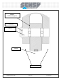
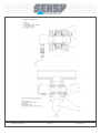
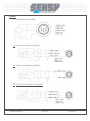
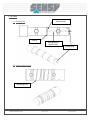
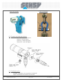
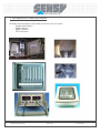
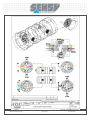
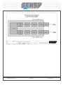
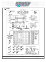
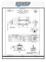
1
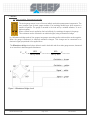
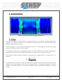
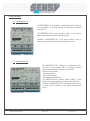
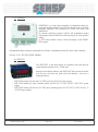
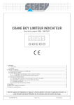
SHEAR-PIN FORCE TRANSDUCER
SERIES 5000-5300-5600
User’s manual
MA-5000-5300-5600 full_EN
Page 1 of 41
Rev: 02/07/2010
1. Introduction .....................................................................................................................................................................................................3
1.1. Force measurement equipment..............................................................................................................................................................3
1.2. Hoisting equipment .................................................................................................................................................................................3
2. Operating conditions of load pin in hoisting devices .......................................................................................................................................4
2.1. Installation ..............................................................................................................................................................................................4
2.2. Operation ................................................................................................................................................................................................4
2.3. Disassembly ...........................................................................................................................................................................................9
3. Periodic inspections ........................................................................................................................................................................................9
4. Wiring ............................................................................................................................................................................................................10
4.1. Typical load cell output signal...............................................................................................................................................................10
4.2. 4-20 mA 3-wire (option J) (see §5.2) ....................................................................................................................................................10
4.3. 4-20 mA 2-wire (option C) (see §5.2) ...................................................................................................................................................10
4.4. 0-10V (1-5V) 3-wire (option T) (see §5.2).............................................................................................................................................10
5. Technical features ........................................................................................................................................................................................11
5.1. General .................................................................................................................................................................................................11
5.2. Electronic ..............................................................................................................................................................................................12
6. Options ..........................................................................................................................................................................................................13
6.1. Greasing hole .......................................................................................................................................................................................13
6.2. Helical greasing groove ........................................................................................................................................................................13
Open clevis sockets .....................................................................................................................................................................................14
6.3. Connector and cable gland options ......................................................................................................................................................14
6.4. Faradization options .............................................................................................................................................................................14
6.5. Multidirectional pin ................................................................................................................................................................................15
6.6. Load pin with external thread ...............................................................................................................................................................15
7. Theory ...........................................................................................................................................................................................................16
7.1. Basic principles: Strain gauge load cells. .............................................................................................................................................16
7.2. Mechanical dimensioning .....................................................................................................................................................................17
7.3. Sensitivity .............................................................................................................................................................................................17
7.4. Factors in signal deterioration ..............................................................................................................................................................20
7.4.1. Disturbances related to force misalignment .................................................................................................................................20
7.4.2. Disturbances related to parasitic forces .......................................................................................................................................21
7.4.3. Disturbances related to binding or wrong assembly ....................................................................................................................21
7.4.4. Disturbances related to impact or overload .................................................................................................................................21
7.4.5. Disturbances related to spurious electromagnetic signals ...........................................................................................................22
7.4.6. Electrical zero drift .......................................................................................................................................................................22
7.5. Calibration ............................................................................................................................................................................................22
8. Electronics .....................................................................................................................................................................................................23
8.1. New Bridgeboy-1R ...............................................................................................................................................................................23
8.2. New Bridgeboy-3R ...............................................................................................................................................................................23
8.3. Crane-boy .............................................................................................................................................................................................24
8.4. DISP PAX .............................................................................................................................................................................................24
9. NEW Application : load limitation and DYNAMIC WEIGHING ......................................................................................................................25
10. NEW Application : load limitation on MOBILE CRANES.............................................................................................................................26
10.1. General diagram .................................................................................................................................................................................26
10.2. Load limiter operation .........................................................................................................................................................................27
10.3. Factory-calculated charts with or without outriggers ..........................................................................................................................28
10.4. Main display ........................................................................................................................................................................................29
11. Customized electronic enclosures ..............................................................................................................................................................30
12. Recording and analysis of overhead crane OPERATION using load pins. Error evaluation ......................................................................32
12.1. Measurement system errors (load pin and electronics)......................................................................................................................32
12.1.1. Errors due to load pins ...............................................................................................................................................................32
12.1.2. Errors due to control electronics ................................................................................................................................................32
12.2. Errors due to hoisting device ..............................................................................................................................................................32
12.2.1. Errors due to the height of the cable ..........................................................................................................................................32
12.2.2. Errors due to friction in the pulley blocks ...................................................................................................................................32
12.2.3. Errors due to dynamic phenomena ............................................................................................................................................33
13. DOUBLE BRIDGE OPTION ........................................................................................................................................................................34
14. Drawings .....................................................................................................................................................................................................37
15. Warranty ......................................................................................................................................................................................................40
MA-5000-5300-5600 full_EN
Page 2 of 41
Rev: 02/07/2010
1. INTRODUCTION
The shear-pin force transducer consists of a cylindrical pin or shaft instrumented with strain gauges to sense
shear strains caused by load. Load pins can be integrated into any mechanical systems, by simple
replacement of an existing pin. SENSY designs and produces a broad range of standard and custom made
load pins (Clevis pin), tailoring their dimensions to your installation.
Shear-pin force transducers are designed for the following applications:
- Load limitation, load indication, load recording of hoisting equipment such as overhead cranes (EOT),
jib cranes, gantry cranes, container cranes, etc.
- Control of strains on civil engineering structures such as suspended road bridges, boat lifts, dams, etc.
- Industrial weighing on mobile and grapple cranes, steel plant cranes, silos, etc.
- Force measurement on mechanical systems such as hydraulic jacks, rolling mills, steel coating
machinery, test benches, etc.
SENSY offers associated electronics tailored to each application.
SENSY load pins are made of high-strength stainless steel and measure a wide range of loads and forces
from 500 N (50 kgf) to 10 MN (1000 tf).
1.1. Force measurement equipment
SENSY force measuring load pins are designed to withstand forces up to 1.5 times higher than the nominal
load without any metrological damage. The mechanical design of the pins is carried out using dedicated
calculation software. CAD and finite elements software are used to define and confirm the robustness of the
pin designs in various environments (industrial, laboratories, harsh marine conditions, etc.)
In force measurement applications, the sensitivity of SENSY load pins can reach 1.5 ... 3mV/V.
1.2. Hoisting equipment
Hoisting load pins are specifically designed for fatigue and occasional static forces 2 times higher than their
nominal load without any metrological and mechanical damage. Beyond twice the nominal load, the reliability
of the measurements is no longer guaranteed (drift beyond 200%). The breaking load is above 5 times the
nominal load. Hoisting load pins are designed to withstand severe dynamic cycles.
MA-5000-5300-5600 full_EN
Page 3 of 41
Rev: 02/07/2010
2. OPERATING CONDITIONS OF LOAD PIN IN HOISTING DEVICES
2.1. Installation
- The delivered pin must be used in the conditions specified in the technical datasheet and according to
the described conditions.
- The force on the pin must be applied in the preferential direction as shown by the arrow. A variation of
± 3° is acceptable.
- Verify that the force on the centre of the pin is in the direction shown by the arrow placed on the
dynamometer. The data sheet provided also mentions this information.
- The pin must be mounted freely in its seating (tolerance H9/h9 sufficient for load limitation; tolerances
H7/h7 are better for load measurements). In the case of rotary applications, we strongly recommend
mounting with bearings (tolerance h6 required optionally on load pins 5000/5600, standard on 5300),
mounting with bushing may be suitable for low rotation speeds (tolerance h7 optional). In this case, the
manufacturer’s specific pressure recommendations must be respected.
- The pin must work only in shear. It should not normally be subject to parasitic strains such as: torsion,
flexion, traction or axial compression. It is therefore necessary to decouple the forces by appropriate
mounting (e.g. use of rolls, or rings of well lubricated bronze).
- The pin cannot be seated by force or by applying heavy impacts. Nevertheless, you may use a wooden
mallet to ensure proper adjustment.
- After seating the pin, it must not have an axial clearance of more than 1° compared to its seating
position.
- The delivered cable must not be extended, but must be kept as short as possible. It is mandatory to
connect the pin to its electronic unit according to the colour codes specified on the pin datasheet,
exclusively and in compliance with the specifications of the electronic unit used. The installation
technician will ensure the integrity of the cable after assembly at site. Any damage to this cable or to
one of the conductors will require replacement by SENSY.
- The load is uniformly distributed over at least 80% of the distance between the junction plates. Written
agreement by the manufacturer is mandatory for particular service conditions.
2.2. Operation
- The shear-pin force transducer is designed to withstand occasional static overload, without damage, up
to 2 x the Nominal Load (case of test load for an overhead crane). In any case, a higher overload
(static or dynamic) is not acceptable.
- Where the bore rotates on the pin (pulley), precautions must be taken to avoid jamming of the pin:
o self lubricated rings
o greasing
o use of a ball bearing.
In case of jamming, the pin must to be returned to us for inspection.
- Make sure that there is no restraint on the deformation of the pin.
- The load handled must be free and compatible with the nominal load of the system:
o no anchorage to the ground or support
o no collision with another load or structure
o no jamming
MA-5000-5300-5600 full_EN
Page 4 of 41
Rev: 02/07/2010
o no impact produced by another load falling on the handled load.
- The pin must not be subject to impacts related to the conditions of use: case of a swinging mono-shaft
colliding with the winch chassis in the swing of the pulley block.
1.
2.
3.
4.
Load pin
Locking plate
Fastening screw
Washers
MA-5000-5300-5600 full_EN
Page 5 of 41
Rev: 02/07/2010
Clearance (min. 0.5 mm)
between
thimble and supports
Locking plate
Load pin
Thimble
Lateral supports
MA-5000-5300-5600 full_EN
Page 6 of 41
Rev: 02/07/2010
MA-5000-5300-5600 full_EN
Page 7 of 41
Rev: 02/07/2010
MA-5000-5300-5600 full_EN
Page 8 of 41
Rev: 02/07/2010
2.3. Disassembly
-
Disconnect the connector
Remove the pin from its tare (also remove it from the assembly: thimble, pulley block…).
Remove the fastening screws of the locking plate.
Remove the locking plate
Remove the pin. Certain pins have internal extraction threads in which bolts can be placed.
Protect the pin from moisture and impacts.
3. PERIODIC INSPECTIONS
- Make sure by appropriate means that the pin has not been jamming (annually).
- Check output for zero load (annually).
Acceptable max.:
± 0.15 mV/V for models 5000, 5300 and 5600
± 6 mA for models 5000-C, 5000-J, 5300-C, 5300-J
± 0.8 V for models 5000-t and 5300-t
- Make sure that the pin beam has not been knocked (markings) or corroded (some corrosive greases).
If there are no such signs of damage, as described in the previous points, simply apply preventive
measures. (Annually)
- In case of doubt, use the diagnostic questionnaire provided with the documentation for the shear-pin
force transducer and consult the manufacturer.
- Check the integrity of the cable.
MA-5000-5300-5600 full_EN
Page 9 of 41
Rev: 02/07/2010
4. WIRING
4.1. Typical load cell output signal
4.2. 4-20 mA 3-wire (option J) (see §5.2)
4.3. 4-20 mA 2-wire (option C) (see §5.2)
4.4. 0-10V (1-5V) 3-wire (option T) (see §5.2)
MA-5000-5300-5600 full_EN
Page 10 of 41
Rev: 02/07/2010
5. TECHNICAL FEATURES
5.1. General
SENSY load pins generally present 1% combined error. This uncertainty arises from the combination of
several errors:
- Error related to temperature drift: with temperature changes, the mechanical behaviour of the steel is
modified and the strain gauge bridge measures a deformation, which is interpreted as an applied force.
The stain gauge bridge is compensated by temperature sensitive resistances for a range from -10 to
+45°C (other compensation ranges on request).
- Non repeatability: two different loadings in identical mechanical conditions do not deliver the same
signal.
- Hysteresis error: applying the same force, the signal is different when the force is increasing than when
it is decreasing.
- Non-linearity error: a load pin does not have perfect signal linearity between zero and full load. The
curve is slightly bent.
- Resolution error: corresponds to the smallest resolution of the digital device
- Calibration error: during the calibration process, an error can occur due to the uncertainty (0.01%) of
the applied force.
Combined error
Non repeatability
Creep over 30 min.
Zero reset
Reference temperatures
Compensated temperatures
Operational temperatures
Storage temperatures
Thermal sensitivity drift
Thermal drift of zero
Nominal sensitivity
Initial range of zero
Input resistances
Output resistances
Insulation resistance
Recommended power supply
Maximum power supply
Nominal load
Acceptable maximum load
Breaking load
%F.S.
%F.S.
%F.S.
%F.S.
°C
°C
°C
°C
%/10°C
%F.S./10°C
mV/V
mV/V
Ω
Ω
MΩ
V
V
%F.S.
%F.S.
%F.S.
<±1…2 *
±0.25
<±0.2
<±0.05
23
-10...+45
-30…+70
-50…+85
<±0.1
<±0.1
0,6…1,5
±0.02
351±2
351±2
>5000
5…12
15
100…200(**)
150…300
>500
* The specific combined error of the pins is about 0.5%. Nonetheless, the installation conditions may have a
negative influence on the linearity and especially on the hysteresis. The greater the support surfaces, the
greater the errors (specific pressure \< 50N/mm²). In order to obtain higher characteristics, shape the pin to
limit areas of friction between the pin shaft and the bore; and use specific pressures >= 100N/mm².
** According to sensitivity
F.S.: Full scale
MA-5000-5300-5600 full_EN
Page 11 of 41
Rev: 02/07/2010
5.2. Electronic
Different types of output signals are available to suit the requirements of the measurement circuits:
- Typical load cell output is expressed in mV/V. Example: for 10V typical power supply, the load pin, for a
200 kN applied force with 1.0 mV/V output will deliver 10mV (10000 μV), with 100kN applied force, it
will deliver 5mV (5000µV).
- Option “J”, 4-20 mA internal amplifier card three-wire: the force measurement is converted into a
current output. This amplifier allows long cable lengths between the sensor and its instrumentation.
After factory calibration, load “0” delivers 4mA and maximum load delivers 20mA.
- Option “C”, 4-20 mA internal amplifier card, two-wire current loop: offers advantages similar to option
“J”.
- Option “T”, 0-10 V (1-5V for hoisting applications) internal amplifier card, three-wire: the signal is
converted to 0-10V (1-5V) output.
- Other amplifier options: RS232, RS485 for direct communication with computer, profiBus, etc.
Type
Resistive
Compensated temperature range
Operating temperature range
Storage temperature range
Power supply
(VDC)
5…10 …12
Bridge impedance
( )
Load impedance
( )
Nominal signal range
Min.
Max.
Electrical saturation
Normal drift (zero)
%/°C
Normal drift (span)
%/°C
350 30
NA
0 – 0. 5 mV/V
0 – 1.7 mV/V
> 2 mV/V
< 0.01
0.01
MA-5000-5300-5600 full_EN
option C
4-20 mA
2 wire
From - 10° to
From - 20° to
From - 50° to
15 - 40
Not regulated
(1000, 5000)
< 1k
4.5 - 9 mA
4.5 – 22 mA
> 24 mA
< 0.03
0.025
Page 12 of 41
option J
option t
4-20 mA
0-10V (1-5 V)
3 wire
3 wire
+ 45° C
+ 80° C
+ 85° C
15- 30*
15- 30*
Not regulated
Not regulated
(350)
(350)
< 0.3k
> 10k
4 - 9 mA
1-5 V
4 - 22 mA
0.2-5.6 V
> 24 mA
> 5.6 V
< 0.03
< 0.03
0.025
0.02
* 12-30V on request
Rev: 02/07/2010
6. OPTIONS
Radial drilling for
lubricant entry
6.1. Greasing hole
Groove
Axial drilling for
lubricant entry
Grease fitting
6.2. Helical greasing groove
Greasing groove
MA-5000-5300-5600 full_EN
Page 13 of 41
Rev: 02/07/2010
Open clevis sockets
Load Cell Shackles
6.3. Connector and cable gland options
Standard use: radial connector
Option A : axial connector
Options G : radial cable gland
Options GA : axial cable gland
6.4. Faradization options
Standard: faradization not connected to the load cell
Option f: faradization connected to the load cell
MA-5000-5300-5600 full_EN
Page 14 of 41
Rev: 02/07/2010
6.5. Multidirectional pin
The multidirectional pin enables measurement of the amplitude and the direction of the force. The pin consists
of two bridges with a 90° phase shift. S1 is the signal of bridge N°1. S2 is the signal of bridge N°2. The angle
between the force and the direction of the bridge N°1:
arctan
S2
S1
The angle between the force and the direction of the bridge N°2:
arctan
S1
S2
90
The amplitude of the force is:
F
S12
S 22
6.6. Load pin with external thread
MA-5000-5300-5600 full_EN
Page 15 of 41
Rev: 02/07/2010
7. THEORY
7.1. Basic principles: Strain gauge load cells.
The strain gauge sensor is one of the most widely used strain measurement components. The
most common type of strain gauge consists of an insulating flexible layer which supports a
metallic foil pattern. The gauge is mounted to the load cell by a suitable adhesive, so as to
deform together.
When a certain force is applied on the load cell body, the resistance changes in the gauge.
This resistance can be converted to an electrical signal, using a Wheatstone bridge.
In a Wheatstone bridge made of four gauges, two gauges are under positive strain and two under negative.
When the gauge is deformed, its electrical resistance changes. This change can be converted to an
electronic signal, proportional to the applied force.
The Wheatstone bridge circuit shown below is used in load cells and other strain gauge sensors, because it
is not sensitive to electromagnetic disturbance.
UA UB
SG1
U a lim entation
SG1 SG 4
SG2
U a lim entation
SG2 SG3
Figure 1 : Wheatstone Bridge circuit
MA-5000-5300-5600 full_EN
Page 16 of 41
Rev: 02/07/2010
7.2. Mechanical dimensioning
Figure 2: Finite element method applied on load cell
7.3. Sensitivity
One of the most important characteristics of a strain gauge sensor is its sensitivity: sensitivity represents the
variation of the output to nominal force. The sensitivity is usually expressed in mV/V (electrical output signal
divided by supply/excitation voltage).
Take the example of a 150 kN load pin with sensitivity 0.9 mV/V: at 10 Volts supply, the excursion of the signal
reaches 9 mV (9000 μV) when 150 kN is applied.
The dimensions of load pins are calculated according to the required sensitivity and customer's requirements.
Increasing the sensitivity involves locally reducing the cross section of the “I” beam profile (figure 4).
The Wheatstone bridge’s signal also depends on the gauge factor (usually noted K). The gauge factor, K, is
defined by:
K
Rgage / Rgage
l /l
The gauge factor is the product of strain and the quotient of change in strain gauge resistance and unstrained
resistance of the strain gauge. Usually, this factor is approximately 2. Increasing the gauge factor makes it
possible to increase the sensitivity of a sensor, while keeping the same mechanical deformations on the load
pin body.
MA-5000-5300-5600 full_EN
Page 17 of 41
Rev: 02/07/2010
Figure 3: Optimal zone - capacity according to diameter 1
1
If your requirement does not fit the present diagram, other mechanical solutions are applicable.
MA-5000-5300-5600 full_EN
Page 18 of 41
Rev: 02/07/2010
Deformation zone
Figure 4: Load pin model. The sensitivity is controlled by adjusting the beam thickness
strain gauge
Figure 5: Detailed view of the bonded strain gauge in its location
MA-5000-5300-5600 full_EN
Page 19 of 41
Rev: 02/07/2010
7.4. Factors in signal deterioration
Deterioration of signals can lead to incorrect readings. Please pay attention to the following factors in order to
avoid signal disturbances.
7.4.1. Disturbances related to force misalignment
The sensing axis of the load cell must be close to the load direction. Maximum 3% alignment error can be
accepted. If the alignment error is higher than 3%, the sensitivity of the axis will decrease, causing a false
result.
The sensitivity depends directly on the cosine of the angle formed by the
sensitivity axis and the load direction.
U corrected
U m easured
cos
For load cells functioning with 4-20 mA the correction is:
I corrected
I m easured 4mA
cos
4mA
Caution! The offset between the sensing axis and the load direction
cannot exceed 10 degrees.
Sensing axis
MA-5000-5300-5600 full_EN
Load direction
Page 20 of 41
Rev: 02/07/2010
7.4.2. Disturbances related to parasitic forces
The load pin is connected in a balanced Wheatstone bridge circuit, and excited by a source of extra-low
voltage, the transducer will produce an electrical output which is a direct linear function of the excitation
voltage and the magnitude of the applied mechanical input
When parasitic components are present on the sensor (forces in a different direction than the sensitivity axis,
couples with unspecified axis), they cause deformation on the load cell where the strain gauges are placed
and produce a false result.
In the best case, the parasitic components will have only a small influence on the behaviour of the load pin.
In the worst case, the measurement will be substantially degraded. It is important that the pins are mounted in
the appropriate direction.
When parasitic forces are unavoidable, SENSY designs special load pins that are not sensitive to such factors.
7.4.3. Disturbances related to binding or wrong assembly
If the signal delivered by the load pin is too weak compared to the applied load, the force is probably not being
freely applied. Binding can cause the deformation of the pin and alter its output.
The commonest form of binding is axial seizure. This occurs when there is insufficient clearance between the
side supports and the central thimble. When the load is applied, a large part of the force is taken up by this
friction, which reduces the result seen in the measurement
7.4.4. Disturbances related to impact or overload
When the load pin is subjected to certain impacts or overload, the zero signal can be modified. The signal is
shifted over the full effective range during the measurement. It is necessary to re-inspect the load pin and
return it to the manufacturer.
In the best case, the zero drift is not significant and the pin has not suffered any permanent deformation. The
instrumentation must be recalibrated.
In certain case, after an impact or severe overload, the load pin may be permanently deformed. Based on the
degree of the deformation, SENSY can decide whether the load pin can be repaired or must be replaced.
The sensor can take overloads of 150% without being damaged (200% for hoisting design).
MA-5000-5300-5600 full_EN
Page 21 of 41
Rev: 02/07/2010
7.4.5. Disturbances related to spurious electromagnetic signals
Electromagnetic fields can influence the signal delivered by the load pin. To prevent these disturbances, it is
important to avoid the proximity of high voltage power lines.
7.4.6. Electrical zero drift
Measurement can be disturbed by electrical zero drift due to modification of the strain gauges resistances
caused by induced current or incorrect power supply.
7.5. Calibration
The load pins are factory-calibrated using a compression facility in order to simulate real application conitions.
For custom made load pins, the calibration can deviate up to 5% compared to on-site calibration because of
the mechanical environment that cannot be 100% reproduced in our factory at a cost effective price level.
It is highly recommended to carry out a calibration on site, using a minimum 60% of the nominal load (allowing
for the tare: pulley block, pulley, etc.).
MA-5000-5300-5600 full_EN
Page 22 of 41
Rev: 02/07/2010
8. ELECTRONICS
8.1. New Bridgeboy-1R
The BRIDGEBOY-1R is designed, in combination with a load cell,
for load limitation of hoisting devices and particularly overhead
cranes (EOT).
The BRIDGEBOY-1R provides "positive safety", it puts itself in
alarm mode whatever the detected fault may be.
Available on BRIDGEBOY-1R, a test button makes it easy to
check normal operation of the whole load limitation circuit.
8.2. New Bridgeboy-3R
The BRIDGEBOY-3R is designed, in combination with a
load cell, for load limitation with 3 set points of hoisting
devices and particularly overhead cranes (EOT).
Details of the set points:
-Overload detection
-Slack cable detection
-Intermediate load detection.
The BRIDGEBOY-3R provides "positive safety", it puts
itself in alarm mode whatever the detected fault may be.
Available on BRIDGEBOY-3R, a test button makes it easy
to check normal operation of the whole load limitation
circuit.
MA-5000-5300-5600 full_EN
Page 23 of 41
Rev: 02/07/2010
8.3. Crane-boy
CRANE-BOY is a load limiter integrating 3 independent safety setpoints and a built-in display. Each of them activates a relay, specially
designed, dedicated and configured for hoists and crane load
applications.
An internal monitoring system controls and guarantees perfect
functioning of the load cell and the electronics by a 4th relay (positive
safety).
A “Test” button makes it easy to check the integrity of the CRANEBOY system.
3 independent safety set-points configurable for overload , intermediate load and/or “slack cable” detection.
4-20 mA, 0-10 V, RS-232C,RS485, ModBus.
8.4. DISP PAX
The DISP-PAXP is the ideal display for visualising the loads lifted at
remote distances thanks to its 4.. 20mA input.
Among its local display features, the DISP-PAXP offers various functions
such as tare, max and min peak and hold detection, and even a
summing function.
- DISP PAXD model (4-20 mA and 0-10 VDC input, 85 to 250 VAC power supply)
- DISP PAXS model (mV input, summing option, 85-250 VAC, 24 VAC, 48 VAC 10-30 VDC), power
supply
- DISP PAXP model (4-20 mA and 0-10 VDC input, summing option, 85- 250 VAC, 24 VAC, 48 VAC, 10
-30 VDC power supply).
MA-5000-5300-5600 full_EN
Page 24 of 41
Rev: 02/07/2010
9. NEW APPLICATION : LOAD LIMITATION AND DYNAMIC WEIGHING
This device comprising a load pin and a DISP PAX makes it possible to display the total load.
It is possible to control the net weight. The advantage of this device is that is avoids underloads and overloads
while loading trucks.
The difference between weighing with grapple and statutory weighing is about 1… 2%.
MA-5000-5300-5600 full_EN
Page 25 of 41
Rev: 02/07/2010
10. NEW APPLICATION : LOAD LIMITATION ON MOBILE CRANES
SENSY has developed a load limitation system for mobile plant combining a series of advanced technologies
for complex mechanical applications.
Load limitation will increase the operating safety of your machines and will enhance the safety of their
surroundings.
Our easy-to-use and flexible software guarantees you ease of configuration and a wide range of settings.
10.1. General diagram
The vehicle is equipped with sensors at several points: lattice boom, boom point, and outrigger.
These instruments are connected to a computer which authorises or refuses lifting, according to the position
and load.
When the combination of loads and the new position become critical, only retraction is authorised (for example
telescopic shortening of the arm).
MA-5000-5300-5600 full_EN
Page 26 of 41
Rev: 02/07/2010
10.2. Load limiter operation
This electronic safeguard enables you to optimise the crane by limiting the position of the arm according to the
applied load. It is possible to define different curves for each applied load. Each point in the zone is related to
a maximum load and to a position.
Working area
Zone 1: maximum load 250 kg.
Zone 2: maximum load 100 kg.
This system also takes account of the influencing parameters which can modify the curves.
For example: the position of the outriggers and slewing platform.
Position
Outriggers are extended horizontally from the
chassis. (Variable parameter)
Pressure
Minimal pressure on the outriggers. This value is
variable
MA-5000-5300-5600 full_EN
Page 27 of 41
Rev: 02/07/2010
Inclination
(Back view)
Outriggers are extended vertically to level and
stabilise the crane (Variable parameter)
10.3. Factory-calculated charts with or without outriggers
Encoding of the curves is easy using a PC or a display
The system can handle up to 14 curves.
Each curve can be adjusted with 15 points.
MA-5000-5300-5600 full_EN
Page 28 of 41
Rev: 02/07/2010
10.4. Main display
Allowed movements
X and Y position
of the arm in the
working area
State of the
sensors
Maximum
authorised
loading
according to
the curve
Real time
load
MA-5000-5300-5600 full_EN
Page 29 of 41
Rev: 02/07/2010
11. CUSTOMIZED ELECTRONIC ENCLOSURES
We design and manufacture custom made enclosures to suit your needs.
- Complex load limitation
- Multiple displays
- Signal conditioner
- ATEX enclosures
MA-5000-5300-5600 full_EN
Page 30 of 41
Rev: 02/07/2010
MA-5000-5300-5600 full_EN
Page 31 of 41
Rev: 02/07/2010
12. RECORDING AND ANALYSIS OF OVERHEAD CRANE OPERATION USING LOAD PINS. ERROR
EVALUATION
It is possible to measure the load lifted by a travelling crane by using a pin mounted at the balancing pulley
(mountings in x/2) or at its fixed point (mountings in x/1).
12.1. Measurement system errors (load pin and electronics)
12.1.1. Errors due to load pins
The errors specific to load pins are either mechanical or thermal.
The mechanical errors (non-linearity, hysteresis and non-repeatability) depend mainly on the load pin
dimensions or the quality of the supports.
For standard SENSY pins mounted in H6 toleranced bores, the error is about 0.5% of the nominal load of the
bridge.
It can be reduced to around 0.2% on demand, on the condition that the load pin is profiled.
On a special pin whose length/diameter ratio is too small, this error can go up to about 5%.
Zero drift and sensitivity according to the temperature are usually insignificant because they do not go over
0.1% for 10°C.
12.1.2. Errors due to control electronics
The errors due to the control electronics are usually insignificant because they do not go over 0.1%.
12.2. Errors due to hoisting device
12.2.1. Errors due to the height of the cable
The higher the load, the smaller the part of cable supported by the load pin.
The size of this error depends on the ratio between the cable weight and the nominal load hoisted.
The only way to cancel this error is to always perform the measurements at the same height..
12.2.2. Errors due to friction in the pulley blocks
The consequence of friction in the various pulleys is that the apparent load on the load pin seems lighter when
the load is being hoisted and heavier when the load is being lowered. It is possible to lessen the influence of
this friction by always taking the measurement after the same hoisting or lowering action.
MA-5000-5300-5600 full_EN
Page 32 of 41
Rev: 02/07/2010
12.2.3. Errors due to dynamic phenomena
Hoisted loads rarely stay still and the resulting acceleration is added to that of gravity. This influence can be
lessened by processing the signal of the load pin with adequate filtering in the electronics and by waiting for
the load to be still.
Finally, we can say that the global measurement error is around 1 to 2% in applications where the dimensions
of the load pin are coherent and where the hoisting device is in good condition.
MA-5000-5300-5600 full_EN
Page 33 of 41
Rev: 02/07/2010
13. DOUBLE BRIDGE OPTION
SENSY can provide sensors with redundant strain gauge bridge.
In this design, two separate strain gauge bridges are bonded on both sides of a single proof body.
This arrangement offers the advantage of having two independent measuring legs for a single load cell. As an
example, refer to the functional block diagram for “2710-BKL-20KN”.
This is advantageous when the reliability of the force measurement is crucial. In this case, the logic device has
to compare the two independent signals. This feature is also useful for any industrial equipment which requires
a single measurement signal but where the maintenance operations are delicate. In this case, if there is a fault
condition, instead of replacing the sensor, all that is required is to switch to the second measuring leg.
MA-5000-5300-5600 full_EN
Page 34 of 41
Rev: 02/07/2010
MA-5000-5300-5600 full_EN
Page 35 of 41
Rev: 02/07/2010
MA-5000-5300-5600 full_EN
Page 36 of 41
Rev: 02/07/2010
14. DRAWINGS
MA-5000-5300-5600 full_EN
Page 37 of 41
Rev: 02/07/2010
MA-5000-5300-5600 full_EN
Page 38 of 41
Rev: 02/07/2010
MA-5000-5300-5600 full_EN
Page 39 of 41
Rev: 02/07/2010
15. WARRANTY
The warranty is applicable subject to compliance with the installation recommendations and general principles
of use. Any particular use not described in the present document is subject to prior written agreement by
SENSY S.A., which is mandatory to maintain its compliance. Only applicable for pins used in overhead crane
operations (HOIS) with electronic load limitation devices.
SAFETY COMPONENTS MARKETED SEPARATELY
SENSY S.A. certifies that the load cells described below and intended for load limitation are in accordance
with the essential requirements defined in the European Directive 89/392/EEC modified by the 93/68/EEC
Directive relating to safety components and 89/336/EEC modified by the 92/31/EEC Directive relating to
"Electromagnetic compatibility".
The technical data supporting this compliance are held at the disposal of the authorities for the full statutory
period.
This declaration is only valid for uses strictly according to the specifications and instruction manual
accompanying and characterising each of our products.
These load cells are defined by their control and dimensional data sheets attached, which are to be read and
kept in a safe place. See the general conditions for use on the back of this certificate.
Products concerned:
- Models 5000, 5300, 5600 (Resistive load cell)
Associated electronics: CRANE BOY, BRIDGEBOY, INDI BOY
- 5000-C, 5000-J and 5300-C, 5300-J (Amplifier 4 – 20 mA integrated)
Associated electronics: MARK E, CRANE BOY P, DISP BOYP, BRIDGEBOYP
These load cells have been designed for hoisting devices and may be used with other electronic load limiters.
In this case, in order to comply with the CE requirements, the customer must verify compatibility between the
electronics (in accordance with the referenced directives in industrial environment) and SENSY load cells.
Regulations: EN954-1 (category 1) (extension 2010-2011), rule FEM 9761; NBN 52-010 / 52-011
EN50281-2 / EN50282-2
According to ISO 13849 and IEC 62061 (SIL)
Date: 20th July 2005
MA-5000-5300-5600 full_EN
JM GILLET
Production Manager
Page 40 of 41
Rev: 02/07/2010
For option C6 or I (use in EX zone) : Caution
The use of sensors in EX zones is only permitted with EX-marked sensors supplied with a certificate issued by
an accredited organisation. Sensors must be used with appropriate safety equipment (intrinsic safety Zener
barrier or isolator) conforming to the required standards shown on the certificate.
The use of junction boxes and cable extenders must be considered in the choice of protection.
After specifying all the components, it is mandatory to check that the sensor’s output voltage remains
compatible with the electronics used and the required accuracy.
SENSY S.A. Z.I. Jumet – Allée Centrale B – 6040
MA-5000-5300-5600 full_EN
JUMET, Tel. : +32 71 25.82.00, Fax : +32 71 37.09.11, www.sensy.com
Page 41 of 41
Rev: 02/07/2010