1
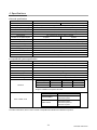
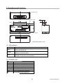
No.EX※※-OMF0012-B
PRODUCT NAME
SI unit
MODEL / Series / Product Number
EX140-SCS#
Table of Contents
1. Safety
2
2. Outline
7
3. Applicable solenoid valves
7
4. Specifications
8
5. Description and Functions
9
5-1 LED indication
9
5-2 Terminal board
9
5-3 Address setting
10
5-4 Setting of Hold/Clear
11
6. Wiring
12
6-1 Communication wiring
12
6-2 Terminal resistance
13
6-3 Cable for communication line
13
6-4 Wiring to power supply
13
7. Troubleshooting
14
-1No.EX※※-OMF0012-B
1. Safety
These safety instructions are intended to prevent hazardous situations and/or equipment damage.
These instructions indicate the level of potential hazard with the labels of "Caution", "Warning" or
"Danger". They are all important notes for safety and must be followed in addition to International
standards (ISO/IEC) ∗1) and other safety regulations.
∗1) ISO 4414: Pneumatic fluid power -- General rules relating to systems.
ISO 4413: Hydraulic fluid power -- General rules relating to systems.
IEC 60204-1: Safety of machinery -- Electrical equipment of machines. (Part 1: General requirements)
ISO 10218-1992: Manipulating industrial robots -Safety.
etc.
Caution :
Warning :
Danger :
CAUTION indicates a hazard with a low level of risk which, if not avoided,
could result in minor or moderate injury.
WARNING indicates a hazard with a medium level of risk which, if not
avoided, could result in death or serious injury.
DANGER indicates a hazard with a high level of risk which, if not avoided,
will result in death or serious injury.
Warning
1. The compatibility of the product is the responsibility of the person who designs the
equipment or decides its specifications.
Since the product specified here is used under various operating conditions, its compatibility with
specific equipment must be decided by the person who designs the equipment or decides its
specifications based on necessary analysis and test results. The expected performance and safety
assurance of the equipment will be the responsibility of the person who has determined its
compatibility with the product. This person should also continuously review all specifications of the
product referring to its latest catalog information, with a view to giving due consideration to any
possibility of equipment failure when configuring the equipment.
2. Only personnel with appropriate training should operate machinery and equipment.
The product specified here may become unsafe if handled incorrectly. The assembly, operation and
maintenance of machines or equipment including our products must be performed by an operator
who is appropriately trained and experienced.
3. Do not service or attempt to remove product and machinery/equipment until safety is confirmed.
1. The inspection and maintenance of machinery/equipment should only be performed after measures
to prevent falling or runaway of the driven objects have been confirmed.
2. When the product is to be removed, confirm that the safety measures as mentioned above are
implemented and the power from any appropriate source is cut, and read and understand the
specific product precautions of all relevant products carefully.
3. Before machinery/equipment is restarted, take measures to prevent unexpected operation and
malfunction.
4. Contact SMC beforehand and take special consideration of safety measures if the product is
to be used in any of the following conditions.
1. Conditions and environments outside of the given specifications, or use outdoors or in a place exposed
to direct sunlight.
2. Installation on equipment in conjunction with atomic energy, railways, air navigation, space, shipping,
vehicles, military, medical treatment, combustion and recreation, or equipment in contact with food and
beverages, emergency stop circuits, clutch and brake circuits in press applications, safety equipment or
other applications unsuitable for the standard specifications described in the product catalog.
3. An application which could have negative effects on people, property, or animals requiring special
safety analysis.
4. Use in an interlock circuit, which requires the provision of double interlock for possible failure by
using a mechanical protective function, and periodical checks to confirm proper operation.
-2No.EX※※-OMF0012-B
Caution
The product is provided for use in manufacturing industries.
The product herein described is basically provided for peaceful use in manufacturing industries.
If considering using the product in other industries, consult SMC beforehand and exchange
specifications or a contract if necessary.
If anything is unclear, contact your nearest sales branch.
Limited warranty and Disclaimer/Compliance Requirements
The product used is subject to the following "Limited warranty and Disclaimer" and "Compliance
Requirements".
Read and accept them before using the product.
Limited warranty and Disclaimer
1. The warranty period of the product is 1 year in service or 1.5 years after the product is delivered,
whichever is first. ∗2)
Also, the product may have specified durability, running distance or replacement parts. Please
consult your nearest sales branch.
2. For any failure or damage reported within the warranty period which is clearly our responsibility, a
replacement product or necessary parts will be provided.
This limited warranty applies only to our product independently, and not to any other damage
incurred due to the failure of the product.
3. Prior to using SMC products, please read and understand the warranty terms and disclaimers noted
in the specified catalog for the particular products.
∗2) Vacuum pads are excluded from this 1 year warranty.
A vacuum pad is a consumable part, so it is warranted for a year after it is delivered.
Also, even within the warranty period, the wear of a product due to the use of the vacuum pad or failure due to
the deterioration of rubber material are not covered by the limited warranty.
Compliance Requirements
1. The use of SMC products with production equipment for the manufacture of weapons of mass
destruction (WMD) or any other weapon is strictly prohibited.
2. The exports of SMC products or technology from one country to another are governed by the
relevant security laws and regulation of the countries involved in the transaction. Prior to the
shipment of a SMC product to another country, assure that all local rules governing that export are
known and followed.
-3No.EX※※-OMF0012-B
Operator
♦This operation manual is intended for those who have knowledge of machinery using pneumatic
equipment, and have sufficient knowledge of assembly, operation and maintenance of such
equipment. Only those persons are allowed to perform assembly, operation and maintenance.
♦Read and understand this operation manual carefully before assembling, operating or providing
maintenance to the product.
■Precautions
Warning
■Do not disassemble, modify (including changing the printed circuit board) or repair.
An injury or failure can result.
■Do not operate the product outside of the specifications.
Do not use for flammable or harmful fluids.
Fire, malfunction, or damage to the product can result.
Verify the specifications before use.
■Do not operate in an atmosphere containing flammable or explosive gases.
Fire or an explosion can result.
This product is not designed to be explosion proof.
■If using the product in an interlocking circuit:
•Provide a double interlocking system, for example a mechanical system.
•Check the product regularly for proper operation
Otherwise malfunction can result, causing an accident.
■The following instructions must be followed during maintenance:
•Turn off the power supply
•Stop the air supply, exhaust the residual pressure and verify that the air is released before performing
maintenance
Otherwise an injury can result.
Caution
■After maintenance is complete, perform appropriate functional inspections.
Stop operation if the equipment does not function properly.
Safety cannot be assured in the case of unexpected malfunction.
■Provide grounding to assure the safety and noise resistance of the product.
Individual grounding should be provided close to the product with a short cable.
-4No.EX※※-OMF0012-B
■NOTE
○Follow the instructions given below when designing, selecting and handling the product.
•The instructions on design and selection (installation, wiring, environment, adjustment, operation,
maintenance, etc.) described below must also be followed.
∗Product specifications
•When conformity to UL is required, the SI unit should be used with a UL1310 Class 2 power supply.
•Use the specified voltage.
Otherwise failure or malfunction can result.
•Reserve a space for maintenance.
Allow sufficient space for maintenance when designing the system.
•Do not remove any nameplates or labels.
This can lead to incorrect maintenance, or misreading of the operation manual, which could cause damage or
malfunction to the product.
•Precautions on handling
∗Installation
•Do not drop, hit or apply excessive shock to the product.
Otherwise damage to the product can result, causing malfunction.
•Tighten to the specified tightening torque.
If the tightening torque is exceeded the mounting screws may be broken.
•Never mount a product in a location that will be used as a foothold.
The product may be damaged if excessive force is applied by stepping or climbing onto it.
∗Wiring
•Avoid repeatedly bending or stretching the cables, or placing heavy load on them.
Repetitive bending stress or tensile stress can cause breakage of the cable.
•Wire correctly.
Incorrect wiring can break the product.
•Do not perform wiring while the power is on.
Otherwise damage to the product can result, causing malfunction.
•Do not route wires and cables together with power or high voltage cables.
Otherwise the product can malfunction due to interference of noise and surge voltage from power and high voltage
cables to the signal line.
Route the wires (piping) of the product separately from power or high voltage cables.
•Confirm proper insulation of wiring.
Poor insulation (interference from another circuit, poor insulation between terminals, etc.) can lead to excess
voltage or current being applied to the product, causing damage.
•Take appropriate measures against noise, such as using a noise filter, when the product is incorporated
into equipment.
Otherwise noise can cause malfunction.
-5No.EX※※-OMF0012-B
∗Environment
•Do not use the product in area that is exposed to corrosive gases, chemicals, sea water, water or
steam.
Otherwise failure or malfunction can result.
•Do not use in an area where surges are generated.
If there is equipment which generates a large amount of surge (solenoid type lifter, high frequency induction
furnace, motor, etc.) close to the product, this may cause deterioration or breakage of the internal circuit of the
product. Avoid sources of surge generation and crossed lines.
•Prevent foreign matter such as remnant of wires from entering the product to avoid failure and
malfunction.
•Mount the product in a place that is not exposed to vibration or impact.
Otherwise failure or malfunction can result.
•Do not use the product in an environment that is exposed to temperature cycle.
Heat cycles other than ordinary changes in temperature can adversely affect the inside of the product.
•Do not expose the product to direct sunlight.
If using in a location directly exposed to sunlight, shade the product from the sunlight.
Otherwise failure or malfunction can result.
•Keep within the specified ambient temperature range.
Otherwise malfunction can result.
•Do not operate close to a heat source, or in a location exposed to radiant heat.
Otherwise malfunction can result.
∗Adjustment and Operation
•Set the switches by using a sharp-pointed screwdriver etc.
It may damage set switches.
•Perform settings suitable for the operating conditions.
Incorrect setting can cause operation failure.
•Please refer to the PLC manufacturer's manual etc. for details of programming and addresses.
For the PLC protocol and programming refer to the relevant manufacturer's documentation.
∗Maintenance
•Turn off the power supply, stop the supplied air, exhaust the residual pressure and verify the release of
air before performing maintenance.
There is a risk of unexpected malfunction.
•Perform regular maintenance and inspections.
There is a risk of unexpected malfunction.
•After maintenance is complete, perform appropriate functional inspections.
Stop operation if the equipment does not function properly.
Otherwise safety is not assured due to an unexpected malfunction or incorrect operation.
•Do not use solvents such as benzene, thinner etc. to clean the product.
They could damage the surface of the body and erase the markings on the body.
Use a soft cloth to remove stains.
For heavy stains, use a cloth soaked with diluted neutral detergent and fully squeezed, then wipe up the stains
again with a dry cloth.
-6No.EX※※-OMF0012-B
2. Outline
(1) CompoBus/S system
Serial transmission system which is composed by OMRON’s PLC (Programmable Logic
Controller) SYSMAC series and CompoBus/S master unit. This system makes it possible to
connect between master and slave including SI unit by only one cable.
(2) SI manifold solenoid valve for CompoBus/S
Manifold type solenoid valve which has remote I/O slave (output unit) connected with Compo
Bus/S system. The number of occupied output point in SI unit can be selected among 16 and
8.
(3) Control of numerous solenoid valves with only one serial transmission cable.
SMC’s SI unit allows epoch-making reduction of wires required by direct serial transmission
from PLC.
(4) High speed communication cycle time
Input and output which can have 256 points in 32 slaves at max. are communicated at speed
of not more than 1msec per cycle.
(5) High flexibility in wiring by the use of T branch and multi drop.
Adoption of T branch and multi drop type enables wiring to be arranged freely and extended
to 100m at max.
(6) Great improvement in ease of maintenance
Only one serial transmission cable as signal line eliminates the difficulty of maintenance due
to mistake and breakage on wiring.
3. Applicable solenoid valves
SQ1000, 2000,
SZ3000
--76-
No.EX̪̪-OMF0012-B
EX##-OMF0012
EX##-OMF0012-A
4. Specifications
♦General specification
Item
Specification
Model
EX140-SCS1
EX140-SCS2
Operating temperature range
Operating: 0 to 55°C, Storage: -20 to +65°C (No freezing or condensation)
Storage temperature range
35 to 85%RH (No condensation)
Withstand voltage
1500VAC for 1 minute, between external terminals and ground
Insulation resistance
500VDC 2MΩ or more, between external terminals and ground
Environment
No corrosive gas and no dust in included
Number of occupied outputs
16 points
8 points
Polarity of output
Sink/NPN (Positive common)
Connected load
24VDC 1.5W (SMC) solenoid valve with circuit protection of surge voltage
Residual voltage
0.4VDC or less
Power supply (Communication)
14 to 26.4V DC
Power supply (Valve)
24V DC -5% to +10%
Current consumption
Communication power supply 0.1A or less (24VDC)
Enclosure
IP20
Weight
80g or less
♦CompoBus/S system specification
Item
Specification
Applicable PLC
OMRON Coop. C200HX/HG/HE, C200HS, CQM1
Communication
Communication for CompoBus/S
Transmission
750kbit/s
Modulation type
Base band type
Coding type
Manchester symbol type
Error control
Manchester symbol check, Frame length check, Parity check
Connection type
T branch, Multi drop
Distance
Cable type
Trunk
Stay
Total of stay
VCTF cable
100m or less
3m or less
50m or less
Specific flat cable
30m or less
3m or less
30m or less
If the number of connected slave is 16 or less, 50m at max for total stay
length is available even specific flat cable.
Master type
Max. number of I/O
C200HW-SRM21
IN128/OUT12/ points or
IN64/OUT64 points
CQM1-SRM21
IN64/OUT64 points,
IN32/OUT32 points or
IN16/OUT16 points
Max. number of I/O
<Note>
For further information, refer to User’s manual of CompoBus/S available from OMRON Corporation.
-8No.EX※※-OMF0012-B
5. Descriptions and Functions
Housing cover
NO.2
NO.18
NO.1
NO.17
Switch cover
LED
PWR. COMM ERR
EX140-SCS1
BS+ BDH BDL BS-
FG
24V
0V
No.
Terminal Board
M3 terminal screw in use.
5-1. LED indication
LED
PWR
COMM
ERR
Content
Lights and lights off as power supply for communication is turned
on and off respectively.
Lights during normal communication and lights off in error or
stand-by of communication.
Lights when communication error occurs and lights off in normal
condition or stand-by of communication.
5-2. B
RATE board
Terminal
Terminal
Connected to
MS+
BS+ of communication power line
BDH
BDH of communication line
BDL
BDL of communication line
BSBS- of communication power line
FG
Ground line
24V
24V of solenoid valve power line
0V
0V of solenoid valve power line
M3 terminal screw in use.
--98-
No.EX̪̪-OMF0012-B
EX##-OMF0012-A
EX##-OMF0012
5-3. Address setting
(1) ADDRESS NO. (Node address)
Setting range of node address depends on type or setting of master as follows.
♦For master unit C200HX/HG/HE or C200HS
If max. number of connected slave is 16(IN8/OUT8), the setting range is 0 to 7.
If max. number of connected slave is 32(IN16/OUT16), the setting range is 0 to 15.
♦For master unit CQM1
The number of channel occupied by PLC of master unit and the number of point occupied by one
node address are related additionally.
Number of CH
occupied by PLC
Number of point occupied
by one node address
IN1/OUT1
8
IN2/OUT2
8
IN4/OUT4
8
IN1/OUT1
4
IN2/OUT2
4
IN4/OUT4
4
Setting range
IN
OUT
IN
OUT
IN
OUT
IN
OUT
IN
OUT
IN
OUT
: 0 to 1
: 0 to 1
: 0 to 3
: 0 to 3
: 0 to 7
: 0 to 7
: 0 to 3
: 0 to 3
: 0 to 7
: 0 to 7
: 0 to 15
: 0 to 15
Max. number of
connected slave
IN 2
OUT 2
IN 4
OUT 4
IN 8
OUT 8
IN 4
OUT 4
IN 8
OUT 8
IN 16
OUT 16
<Note>
• Duplication of node address in different slaves may cause communication error.
• 16 points slave is assigned to be made contained into one channel though it occupies 2 slaves with 8
points. Therefore, node address which are not set to the slave are used as follows.
If set node address is odd, :Node address with no. just before is also used.
If set node address is even : Node address with no. just after is also used.
For example, if node address 5 is set to 16 points SI unit (a kind of slave), node address 4 is also
used for the SI unit.
• For master unit CQM1, if 8 points slave is connected during 4 points mode in it, the slave is
considered to occupy points for 2 slaves and node address just after set node address to the slave is
also used. If the node address is duplicated with another slave, communication error occurs and
makes it impossible to start communication with CompoBus/S.
• During 4 points mode, 16 points slave is not available.
-10-9-
No.EX̪̪-OMF0012-B
EX##-OMF0012
EX##-OMF0012-A
(2) Switch setting
Open the terminal board cover on the upper section of SI unit and set the DIP switch.
1
ON
0
1
2
3
4
5
6
OFF
Node address
Hold/Clear
♦Setting of node address
In SW1 to 4, setting of node address as follows is required. 0:OFF
Node address SW1 SW2 SW3 SW4
Node address SW1
0
0
0
0
0
8
0
1
1
0
0
0
9
1
2
0
1
0
0
10
0
3
1
1
0
0
11
1
4
0
0
1
0
12
0
5
1
0
1
0
13
1
6
0
1
1
0
14
0
7
1
1
1
0
15
1
1:ON
SW2
0
0
1
1
0
0
1
1
SW3
0
0
0
0
1
1
1
1
SW4
1
1
1
1
1
1
1
1
5-4 Setting of Hold/Clear
This setting is intended to determine whether output of SI unit should be hold or cleared totally
when communication error occurs.
In SW5, setting becomes available as follows. 0: OFF 1: ON
Hold/Clear
SW5
Clear
0
Hold
1
<Note>
Stay SW6 off in use.
--1110 -
EX##-OMF0012-A
No.EX̪̪-OMF0012-B
EX##-OMF0012
6. Wiring
6-1 Communication line
There are two connection types are available for slave of CompoBus/S, which are T branch and
Multi drop. In T branch, slave is connected to stay branched from trunk and in Multi drop, slave is
connected directly to trunk. However, in both types, it is impossible to branch from stay. And to
branch stay from trunk, specific crimping connector or commercial terminal base is required.
For connection of communication to SI unit, it is necessary to connect BDH and BDL of
communication line to BDH and BDL of terminal respectively and also BS+ and BS- of
communication power supply to BS+ and BS- of terminal respectively.
Crimping connector for branch
Master Unit
BDH
Terminal
Resistanse
BDL
Stabilized
power supply
Specific flat
cable
BS+ BDH BDL BS- FG 24V 0V
BS+ BDH BDL BS- FG 24V 0V
SI Unit
SI Unit
Class 3 Stabilized
ground power supply
Class 3 Stabilized
ground power supply
This SI unit is multi power supply type slave and equips two separate power ports for communication and
solenoid valve. The port for communication can be supplied through specific flat cable, but one for
solenoid valve can’t and needs separate power supply. And the separate power supply can give the
power to the port for communication.
Wiring order in specific flat cable for communication power supply and line is specified as follows.
Power supply+ (BS+)
Brown
Line High (BDH)
Black
Line Low (BDL)
White
Power supply- (BS-)
Blue
•To
Toprotect
protect the
the system
separate
cable
for for
communication
from from
power
line and
system from
fromnoise
noiseeffect,
effect,
separate
cable
communication
power
linehigh
and high
voltageline.
line.And
Andmind
mind that
that incorrect
incorrect wiring
and
eripheral
equipment.
voltage
wiring order
ordermay
maydamage
damageSISIunit
unit
and
peripheral
equipment.
•The applicable screwdriver is a Phillips head screwdriver with end size of #2 and diameter of ɍ6 or less.
The screws should be tightened securely with a tightening torque of 0.5 to 0.6 Nm.
--1211 -
No.EX̪̪-OMF0012-B
EX##-OMF0012-A
EX##-OMF0012
6-2 Terminal resistance
For stable communication, terminal resistance needs to be mounted to the trunk end located in
opposite side of master (i.e. the most far end from master). And in use, the terminal resistance
shall be prepared from OMRON Corp. with reference below.
SRS1-T
Terminal base with
terminal resistance.
Available in both VCTF and
specific flat cable.
SCN1-TH4T
Crimping connector with
terminal resistance.
Available in only specific flat
cable.
For connection of communication cable to terminal base with terminal resistance, it is
necessary to connect BDH and BDL of communication line to adequate each of terminal.
If the slave at the trunk end is connected in T branch, it is necessary to connect terminal
resistance by the cable longer than length of stay branched from trunk so that the terminal
resistance would be positioned the most far from master.
6-3 Cable for communication line
Type
Specification
VCTF cable (available
on the market)
Vinyl code VCTF JIS C3306
2 cores, Nominal section 0.75mm2 (Signal line × 2)
Conductor resistance(at 20°C) : 25.1Ω/km
Specific flat cable
SCA1-4F10 (100m)
Nominal section 0.75mm2 × 4 (Signal line × 2, Power
line × 2)
Ambient temp. : 60°C or less.
6-4 Wiring to power supply
This SI unit is multi power supply type slave and has two power ports for communication and
solenoid valve.
(1) Power supply for communication
• If VCTF is used in communication line, power is supplied for SI unit by different cable.
• If specific flat cable is used in communication line, power is supplied for SI unit by the flat cable.
(2) Power supply for solenoid valve
Power supply DC24V, -5%, +10% needs to be prepared and connected. The power supply and
used cable shall be selected with consideration of current consumption of solenoid valve and
SI unit. This power supply can give the power for communication of SI unit.
<Note>
The separate power supply should have margin in its capacity enough for rush current at start.
•Insulate
Insulate the
the core
core of
of of
power
at its
end.
of specific
specificflat
flatcable
cableunused
unusedforforsupply
supply
power
at its
end.
•The applicable screwdriver is a Phillips head screwdriver with end size of #2 and diameter of ɍ6 or less.
The screws should be tightened securely with a tightening torque of 0.5 to 0.6 Nm.
--1312 -
No.EX̪̪-OMF0012-B
EX##-OMF0012
EX##-OMF0012-A
7. Troubleshooting
Following is flow chart to eliminate the cause of operating failure in SI unit.
For troubleshooting for whole system, refer to User’s manual for CompoBus/S available from OMRON
Corp.
The solenoid valve
doesn’t operate.
LED on solenoid
valve lights?
YES
Contact SMC.
NO
NO
PWR LED lights?
Power for
communication is
supplied?
NO
Supply the power
for communication.
YES
COMM LED
lights?
YES
Node address is
set correctly?
NO
Correct setting of
node address.
NO
YES
Check the ERR LED
indication, serring of PLC,
program and wiring.
Refer to the OMRON
Corp. User’s manual, etc.
for details.
Even after that, the
normal condition can’t be
obtained, please contact
SMC.
YES
Power for solenoid
valve (24VDC) is
supplied?
--1413 -
NO
Supply the power
for solenoid valve
(24VDC).
No.EX̪̪-OMF0012-B
EX##-OMF0012
EX##-OMF0012-A
Revision history
B: Contents revised in several places.
Note: Specifications are subject to change without prior notice and any obligation on the part of the manufacturer.
© 2002-2014 SMC Corporation All Rights Reserved
No.EX※※-OMF0012-B