1
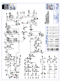
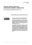
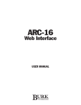
Silence
Sensor
USER MANUAL
Silence Sensor User Manual
Revision B (April 2005)
Copyright © 2005 Burk Technology, Inc. All rights reserved. No part of this manual may be reproduced in any form or by any
means without written permission from Burk Technology. Information in this manual is subject to change without notice.
Contents
CHAPTER 1: INTRODUCTION ................................................................................................................1
Contacting Burk Technology.......................................................................................................................................................1
CHAPTER 2: INSTALLATION & SETUP ....................................................................................................3
Rear Panel Connections ...............................................................................................................................................................3
Voltage Selection ...........................................................................................................................................................................3
Front Panel Controls .....................................................................................................................................................................4
DIP Switches ...................................................................................................................................................................................4
Level Adjustment............................................................................................................................................................................5
APPENDIX A: SPECIFICATIONS & WARRANTY ........................................................................................7
APPENDIX B: TECHNICAL DESCRIPTION.................................................................................................9
CUSTOMER SUPPORT: 978-486-3711 • [email protected] • www.burk.com
iii
iv
SILENCE SENSOR USER MANUAL
1
Introduction
The Silence Sensor makes it easy to monitor the presence of audio by sensing and detecting the loss of audio at
your site.
Activation consists of two stages: an open-collector output on "silence" and another open-collector output plus
relay closure on "time-out". The presence of audio is the control mechanism. You can set the "time-out"
activation for up to 99 seconds or 99 minutes after the loss of program audio on both left AND right channels.
Setup of the unit is accomplished by removal of the front panel cover plate. This small plate provides access to
the DIP switches that select the time for activation following the loss of program audio.
The front panel has three LED indicators. These are labeled as TIME OUT, SILENCE, and POWER. These provide
signal when:
POWER:
SILENCE:
TIME OUT:
LED ON when AC power is applied to the unit.
LED ON when the unit recognizes silence.
LED ON when the unit has recognized silence for the set time period and relay output has been
activated.
The unit recognizes both rising and falling edges of audio. In addition, it observes audio on a wide band basis,
and in a narrow band manner at 470 Hz. This permits the unit to ignore hum and other false signals.
CONTACTING BURK TECHNOLOGY
Customer Support
Visit the Support section of our website at www.burk.com/support/ for troubleshooting tips, documentation and
downloads. If you still need help, please contact Burk Technology Customer Support:
Phone:
Fax:
Email:
978-486-3711
978-486-0081
[email protected]
CUSTOMER SUPPORT: 978-486-3711 • [email protected] • www.burk.com
1
CHAPTER 1: INTRODUCTION
Sales
For information on Burk Technology's line of transmitter remote control systems and accessories, please visit our
website at www.burk.com, or contact a sales engineer:
Phone:
Fax:
Email:
2
800-255-8090 (Main Sales Office)
800-736-9165 (Kansas City Sales Office)
978-486-0081
[email protected]
SILENCE SENSOR USER MANUAL
2
Installation & Setup
REAR PANEL CONNECTIONS
All interfacing to and from the Silence Sensor is made through the back panel barrier strip, as shown in Figure 1.
Two audio input connections are provided for stereo stations, labeled RIGHT and LEFT. Mono audio can be
applied to either channel.
The "S" (Silence) terminal provides an open collector closure (250 mA maximum) to ground when the terminal
senses the program audio is lost on both left AND right channels.
Note: The loss of audio to both the left and right channels triggers the Silence Sensor's closure to ground.
The "TO" (Timed Out) terminal provides an open collector closure (250 mA maximum) to ground when program
audio has been absent for greater than the time period set with the front panel DIP Switches; i.e. the unit has
"Timed Out".
The "LED COM" terminal provides voltage for LED indicators that can be controlled by the S and TO contacts.
No voltage dropping resistor is required as it is already located in the unit.
The "+5V" terminal provides +5 VDC output to power external relays, if desired. The relay path would be
completed by S or TO.
The "NO, NC, C" terminals provide access to the internal relay controlled by the Silence Sensor unit. When
audio is present, the NC and C contacts are shorted. Without the presence of audio, the NO and C contacts are
connected.
VOLTAGE SELECTION
The Silence Sensor can operate on either a 120 or 240 Volt AC line. The unit is shipped from the factory
configured for 120 VAC.
WARNING! If a voltage change is required, disconnect the unit from power before proceeding to prevent electrical shock.
To change the unit for 240 VAC operation:
1. Remove the cover and locate the Molex connector attached to the primary of the transformer. Note that a
white connector is plugged into it. The white connector is used when the unit is connected to 120-volt
circuits.
CUSTOMER SUPPORT: 978-486-3711 • [email protected] • www.burk.com
3
CHAPTER 2: INSTALLATION & SETUP
2. Attached to the white connector is a similar red connector. The red connector must be used when the unit
is connected to 120-volt circuits.
3. Unplug the white connector and replace it with the red connector.
4. Replace the cover before applying power to the unit.
FRONT PANEL CONTROLS
The front panel controls consist of a bank of 10 DIP switches and a trimmer potentiometer. The switches or level
adjustment only need to be set at the time of installation, or when a timing change is required. DIP Switches and
Level Adjustment are located behind the removable panel on the front of the unit.
DIP SWITCHES
The switches are used to set the required delay time before the Silence Sensor reacts to a loss of program audio.
Switch #1 is the first switch (left to right) and switch #10 is the last switch when viewed from the front. The
DIP switch functions are listed below:
Switch
Position
Description
1
UP
Selects seconds mode for setting time delay
DOWN
Selects minutes mode for setting time delay
2
N/A
Not used
3
UP
Selects 80 time units of delay (minutes or seconds)
DOWN
No setting
UP
Selects 40 time units of delay (minutes or seconds)
DOWN
No setting
UP
Selects 20 time units of delay (minutes or seconds)
DOWN
No setting
UP
Selects 10 time units of delay (minutes or seconds)
DOWN
No setting
UP
Selects 8 time units of delay (minutes or seconds)
DOWN
No setting
UP
Selects 4 time units of delay (minutes or seconds)
DOWN
No setting
UP
Selects 2 time units of delay (minutes or seconds)
DOWN
No setting
UP
Selects 1 time unit of delay (minutes or seconds)
DOWN
No setting
4
5
6
7
8
9
10
4
SILENCE SENSOR USER MANUAL
CHAPTER 2: INSTALLATION & SETUP
Example 1: Setting Time Delay of 29 Minutes
Switch
Position
Description
1
DOWN
Sets unit for minutes mode for setting time delay.
5
UP
Selects 20 time units (minutes)
7
UP
Selects 8 time units (minutes)
10
UP
Selects 1 time units (minutes)
Note: All other switches not being used should be set in the DOWN position.
Example 2: Setting Time Delay of 99 Minutes
Switch
Position
Description
1
DOWN
Sets unit for minutes mode for setting time delay.
3
UP
Selects 80 time units (minutes)
6
UP
Selects 10 time units (minutes)
7
UP
Selects 8 time units (minutes)
10
UP
Selects 1 time units (minutes)
Note: All other switches not being used should be set in the DOWN position.
Example 3: Setting Time Delay of 45 Seconds
Switch
Position
Description
1
UP
Sets unit for seconds mode for setting time delay.
4
UP
Selects 40 time units (seconds)
8
UP
Selects 4 time units (seconds)
10
UP
Selects 1 time units (seconds)
Note: All other switches not being used should be set in the DOWN position.
LEVEL ADJUSTMENT
The trimmer potentiometer is used to set the level of input program audio to which the Silence Sensor responds.
To set this control, apply program audio (at the level at which it will normally be used) to the audio input
connector on the back of the unit. Set the control fully counter-clockwise. Turn this control clockwise to a point
about 1/10 of a turn beyond the point where the Silence LED extinguishes. The exact setting of this control is
dependent on program content. Certain formats require that it be advanced slightly less or more.
CUSTOMER SUPPORT: 978-486-3711 • [email protected] • www.burk.com
5
6
SILENCE SENSOR USER MANUAL
A
Appendix A:
Specifications & Warranty
Dimensions:
19” W x 6.25” D x 1.75” H
Weight:
7 lbs.
Power Requirements:
117 to 234 VAC, 50 to 60 Hz, 12 Watts
Rear Panel Connections:
14 position barrier strip
Inputs:
Active balanced bridging
Outputs:
Open collector, rated 48 VDC, 250 mA. Relay Omron G6A-234P-DC5.
CUSTOMER SUPPORT: 978-486-3711 • [email protected] • www.burk.com
7
APPENDIX A: SPECIFICATIONS & WARRANTY
WARRANTY
Burk Technology, Inc. warrants the Silence Sensor to be free of defects in materials and workmanship for a period
of 24 months from the date of purchase. Equipment will be repaired or replaced at the option of Burk
Technology and returned freight prepaid to the customer. Damage due to abuse or improper operation or
installation of the equipment or caused by fire or flood or harsh environment is not to be covered by this
warranty. Damage in shipping is not the responsibility of Burk Technology. A return authorization must be
obtained before returning any equipment. Materials returned under this warranty must be shipped freight
prepaid and insured in the original shipping carton or suitable substitute to Burk Technology, 7 Beaver Brook
Road, Littleton, MA 01460. Repairs not covered under this warranty will be made at prevailing shop rates
established by Burk Technology, Inc.
THE WARRANTY SET FORTH ABOVE IS IN LIEU OF ALL OTHER WARRANTIES, EXPRESS OR IMPLIED,
INCLUDING BUT NOT LIMITED TO THE WARRANTIES OF MERCHANTABILITY AND FITNESS FOR A
PARTICULAR PURPOSE. BURK TECHNOLOGY, INC. SHALL NOT BE LIABLE TO ANY PARTY FOR ANY
INCIDENTAL, SPECIAL, INDIRECT OR CONSEQUENTIAL DAMAGES ARISING FROM THE USE OF THIS
EQUIPMENT.
8
SILENCE SENSOR USER MANUAL
B
Appendix B:
Technical Description
Note: Please refer to the schematic on the following page while reading through this technical description.
The audio to be monitored is applied to U4A and U4D, unity gain instrumentation amplifiers. Level to the audio
detection filter is set by R17 and the amplifier U9D. C27, a 2.2 uF capactitor allows detection of broad band
audio. U9A, U9B and U9C detect presence of audio at 470 Hz.
The broad band and 470 Hz detectors are level compared by U8A and U8B. If sufficient audio exists in both of
these spectrums, U3A will not trigger. A triggering of U3A implements controls to drive the SILENCE LED and S
open-collector output and also restarts and clears the timer circuitry. By changing the DIP switch selections of
S1, the user can program the elapsed time before U11C and U11D (a set/reset latch) trigger the TIMEOUT.
Notice that the restart signal derived from the filters also resets the U11C, U11D latch. This allows the clearing
of the TIMEOUT function upon the return of audio.
The TIMEOUT output, when active, lights the corresponding front panel LED, provides the TO driver, and
energizes the K1 relay thus connecting the NC and C contacts.
CUSTOMER SUPPORT: 978-486-3711 • [email protected] • www.burk.com
9